Single light Webinar new Afternoon sessions
27
© ifm © ifm 1 19.08.2020
Transcript of Single light Webinar new Afternoon sessions

© ifm© ifm 119.08.2020

© ifm 219.08.2020
Rylance Sukdao Sales Manager KZN
ifm electronic South Africa27-29 Jan Hofmeyr Road Westville , DurbanPhone +27 31 266 6465Cell +27 82 804 5363E-mail [email protected] www.ifm.com

© ifm 319.08.2020
Overview
Introduction
The need for indication signals and their requirements
Technical Features of the signal lamp
Various components that allow for different mounting options
The different operating modes of the signal lamp
LR Device software
Question and answers

© ifm 419.08.2020
Introduction
The smooth operation of any process or machinery requires proper indication , but it can be
challenging when a large number of machine statuses need to be differentiated.
Automated machinery and work cells today can be very fast-paced and may serve multiple
functions at one time.
With operators performing multiple tasks in the same work area, the potential for error is high.
Machines or work stations may also have many different statuses, and without versatile
indication options, correct identification by the operators could pose as a problem
To prevent errors, as well as streamline assembly processes, proper indication can elevate
productiveness and increase overall efficiency .

© ifm 519.08.2020
Why do we need indication signals?
Lets look at a typical production line….. The machine is equipped with sensors that inform the operator of various events
Red LED to indicate a fault or error Orange LED to indicate manual mode / maintenance
Green LED to indicate healthy / run state
Label not detected by a bar code scanner
Incorrect size of packaging
Drop in hydraulic pressure on the press
E-stop is activated
Obstruction sensed by the light curtains
Any process value that goes beyond its critical range
1. To know the current state of the machine
2. To alert the operator of warning conditions
3. To alert all personnel of an emergency situation

© ifm
What can we use to indicate these different conditions ?
Conventional tower light (For machine states)
Conventional Blinking lights (For machine warning
conditions)
Siren & Buzzer (For emergency conditions)

© ifm
What requirements should an indicating signal conform to? 1. Luminance (0 to 100%)
This should ideally be adjustable to conform to a high level of luminance in bright conditions and a decreased level in lower lighting environments
2. Blinking and flashing (slow/medium/fast) Operators can link different sequencing of blinking/flashing to differentiate events
Eg . Blinking is used for unacknowledging events/ new faults
Flashing is used in safety breaches, or critical levels where a manual reset is required
3. Audible range of the buzzer( 0 to 100%) Sound of the buzzer should be able to adapt to the ambient noise in the environment
A higher volume will be required in noisy areas in the plant
A lower setting should be allowed for quieter areas so as not to reach damage levels of hearing

© ifm 819.08.2020
Taking in consideration of the mentioned requirements ……
Adjustable Luminance Adaptable flashing/blinking rates Buzzer with adjustable audible sound
Single segment signal lamp by IFM

© ifm
Technical features of the signal lamp
• Highly visible in all ambient conditions
• Adjustable Loud Buzzer (90db) with selectable melodies
• 7 selectable colors
• Permanent light, 3 blinking modes, 3 flashing modes
• High ingress protection rating IP 67/65, making it suitable for wet areas
• Simple installation with M30 fixing nut / Pole mounting
• Integrated capacitive touch button on cap
• Three operating modes
1. Basic On /Off mode
2. RGB Mode
3. IO Link mode

© ifm
Various components & Mounting methods
Different variations of the lamp
DV2120 – Standard
DV2121 – With touch input
DV2130 – With buzzer
DV2131 – with buzzer touch input
1st mounting method : M30 connection

© ifm
2. Pole / wall mounting
1. Choose lamp D DV2XXX
2. Adapter E89080
3. Choose Pole
4a Base mount E89060
4b Wall mount E89061
E89065 - 100mm
E89066 - 300mm
E89067 - 800mm

© ifm
Operating modes of the lamp • SIO / ON OFF Mode
In this mode, three colors can each be selected using a separate connection pin
This makes it possible to easily replace conventional lamps that have more than one lighting segment.
The buzzer and the pushbutton can be activated using a further pin of the M12 socket.
Wiring for on/off Mode

© ifm
Operating modes of the lamp • RGB Mode
In the "RGB mode", the three digital inputs have a fixed functionality.
Here every input is dedicated to one of the three basic colors "red, green, blue".
If LED-A is high, the segment is Red , if LED-B is high, light is Green and if C is high, light is Blue
If Input LED-A and LED-B are high, the combination of red AND green = yellow.
Wiring for RGB Mode

© ifm
Operating modes of the lamp
• IO Link Mode
IO Link allows for the use of the ON/OFF and RGB Modes using a single 3 wire connection
In the IO-Link mode, the single light can be configured and also controlled via the process-data communication
between IO-Link master and the signal light.
The user can control the color of the light, the intensity and the flashing frequency, he can control the Buzzer
style, can switch on and off the buzzer and can read the status of the feedback button on top of the single light.
Wiring for IO Link Mode

© ifm
What is IO Link ?
19.08.2020 15
Input Output – Link
Approved solution for the connection of sensors and actuatorsIs an IEC 61131-9 global standard digital communication protocol
Point- to-point bi-directional connection → not a bus system!
IO-link allows the transfer of
process data parameters events / diagnostic data
© ifm
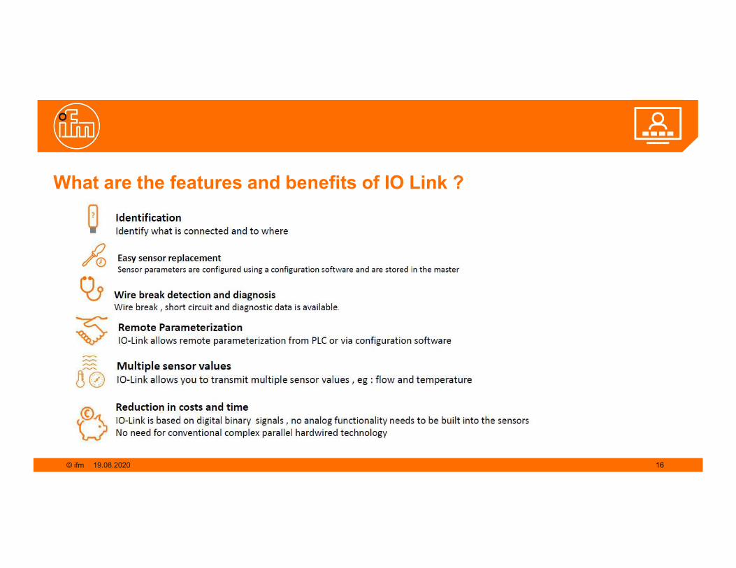
What are the features and benefits of IO Link ?
19.08.2020 16

© ifm
IO Link is an open vendor technology
19.08.2020 17

© ifm
What is required for IO Link communication to our signal light ?
LR Device software
QA0011E30390
IO Link interface
IO Link masters

© ifm
What settings can be changed using LR device ? Lets have a look at the software online …
LR Device

© ifm 2019.08.2020
Cyclic data comes through a 2 words
1st word: Pdin – only 1 bit is used for the status of
the capacitive button
2nd word: Data is represented in 2 ways depending
if ON/OFF mode or RGB mode is chosen
In ON/OFF mode , the controller switches the LED
segment and the buzzer on and off via cyclic data.
The signaling corresponds to the parameters
previously defined for the LED segment and the
buzzer (previous setting with LR device)
How is the data transfer to and from the PLC identified ?
PD IN
PD OUT (on/off mode)

© ifm 2119.08.2020
How is the data transfer to and from the PLC identified ?
Setting of the LED properties (RGB Mode)
PD OUT (RGB Mode)
The next 3 bits of byte 0 allows for the segment to flash /blink at different rates
The 1st 4 bits of byte 0 allows for the appearance of the segment to be various colors

© ifm 2219.08.2020
How does the data come to the PLC ?
Setting of the Buzzer properties (RGB Mode)
PD OUT (RGB Mode)
The 1st bit of byte 1 is to switch the buzzer on / off
The buzzer style can be set in 8 different modes and this is achieved by the various bit combinations for positions 4,5 and 6 as shown in the adjacent table
© ifm
Summary Now that it has been established that there could be some intelligence in a simple light, it can be safe to say that this signal
lamp could become a tool in increasing efficiency to some degree……
Severity of a breakdown can be intensified by increasing the audibility and intensity of the light segment in the aim to
shorten the time taken to attend to a breakdown.
IO Link communication allows for operators to be signaled during an event down to the sensor level before the process
is interrupted or production could be affected…..this is allows for Real Time maintenance
Timeous acknowledgment of alarm/warning statuses via integrated touch button reduces the need for an extra sensor
saving on cost
Utilizing the IO Link functionality allows for flexible signaling that is achievable with a 3 wire connection saving on cost of
cabling as well as additional input modules to the PLC .
Flexibility of the signal lamp could also allow for reducing inventory part numbers , contributing to further cost saving

© ifm
Q & A

© ifm 2519.08.2020
Webinar Schedule
26 August 2020 IO Link Precise Pressure Sensor with Temperature Monitoring
https://www.ifm.com/za/en/za/webinars/2020See the next webinars at the link below:

© ifm 2619.08.2020
ifm electronic – Pty LTD - ZA https://www.youtube.com/user/ifmelectronic www.linkedin.com/company/ifm
ifm South Africa
Follow us on Social Media

© ifm© ifm
Please contact us:
@ ifm
Thank you for participating
Rylance Sukdao
Sales Manager KZN ifm electronic South Africa
27-29 Jan Hofmeyr Road Westville , DurbanPhone +27 31 266 6465Cell +27 82 804 5363E-mail [email protected] www.ifm.com
Johan Van Niekerk
New businessDevelopmentManagerKey accounts
ifm electronic South Africa112 Sovereign DriveR21 Corportate ParkIrene CenturionPhone +27 12 450 0400E-mail [email protected] www.ifm.com