![ch09-Dislocations & Strengthening Mechanisms [호환 모드] · AMSE 205 Spring ‘2016 Chapter 9 - 16 Adapted from Fig. 9.10, Callister & Rethwisch 9e. (Photomicrograph courtesy](https://static.fdocuments.net/doc/165x107/5f46fde78b67a5753712d19f/ch09-dislocations-strengthening-mechanisms-eeoe-amse-205-spring.jpg)
Single Crystal Slip Adapted from Fig. 7.8, Callister 7e. Adapted from Fig. 7.9, Callister 7e.
15
Single Crystal Slip Adapted from Fig. 7.8, Callister 7e. Adapted from Fig. 7.9, Callister 7e.
-
Upload
hugo-lynch -
Category
Documents
-
view
330 -
download
1
Transcript of Single Crystal Slip Adapted from Fig. 7.8, Callister 7e. Adapted from Fig. 7.9, Callister 7e.

Single Crystal Slip
Adapted from Fig. 7.8, Callister 7e.
Adapted from Fig. 7.9, Callister 7e.

Calculation of Theoretical Shear Stress for a Perfect Lattice
G. Dieter, Mechanical Metallurgy, 3rd Edition, McGraw-Hill, 1986.

Dislocation Concept
• Concept of dislocation was first introduced to explain the discrepancy between observed and theoretical shear strengths
• For the dislocation concept to be valid:1. The motion of a dislocation through a lattice must require less stress than
the theoretical shear stress
2. The movement of dislocations must produce steps or slip bands at free surfaces
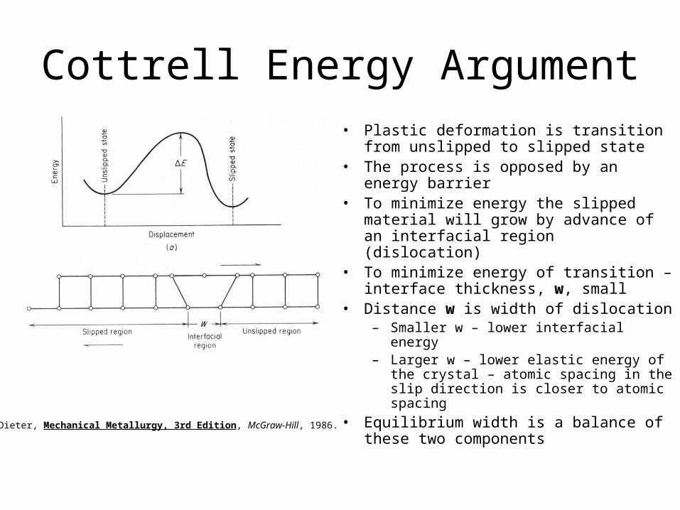
Cottrell Energy Argument• Plastic deformation is transition from
unslipped to slipped state• The process is opposed by an energy
barrier• To minimize energy the slipped material
will grow by advance of an interfacial region (dislocation)
• To minimize energy of transition – interface thickness, w, small
• Distance w is width of dislocation– Smaller w – lower interfacial energy– Larger w – lower elastic energy of the
crystal – atomic spacing in the slip direction is closer to atomic spacing
• Equilibrium width is a balance of these two componentsG. Dieter, Mechanical Metallurgy, 3rd Edition, McGraw-Hill, 1986.

Peierls-Nabarro Force• Dislocation width determines the force required to move a dislocation
through a crystal lattice
• Peierls stress is the shear stress required to move a dislocation through a crystal lattice
• Note: wide dislocations require lower stress to move– Makes sense: Wide – the highly distorted region at core is not localized on any
particular atom
• In ductile metals the dislocation width is on the order of 10 atomic spacings
b
aG
b
wGp
1
2exp
1
22exp
1
2
a is distance between slip planesb is the distance between atoms in the slip direction
In ceramics with directional covalent bonds – high interfacial energy, dislocations are narrow – relatively immobileCombined with restrictions on slip systems imposed by electrostatic forces – low degree of plasticity

Dislocation Motion
• Covalent Ceramics (Si, diamond): Motion hard. -directional (angular) bonding
• Ionic Ceramics (NaCl): Motion hard. -need to avoid ++ and - - neighbors.
+ + + +
+++
+ + + +
- - -
----
- - -
• Metals: Disl. motion easier. -non-directional bonding -close-packed directions for slip. electron cloud ion cores
++
++
++++++++ + + + + +
+++++++

Dislocation MotionDislocations & plastic deformation• Cubic & hexagonal metals - plastic deformation by plastic shear
or slip where one plane of atoms slides over adjacent plane by defect motion (dislocations).
• If dislocations don't move, deformation doesn't occur!
Adapted from Fig. 7.1, Callister 7e.

Dislocation Motion
• Dislocation moves along slip plane in slip direction perpendicular to dislocation line
• Slip direction same direction as Burgers vector
Edge dislocation
Screw dislocation
Adapted from Fig. 7.2, Callister 7e.
– Slip plane - plane allowing easiest slippage:• Minimize atomic distortion (energy) associated with dislocation
motion• Wide interplanar spacings - highest planar atomic densities (Close
Packed)
– Slip direction - direction of movement• Highest linear atomic densities on slip plane
Definition of a Slip System
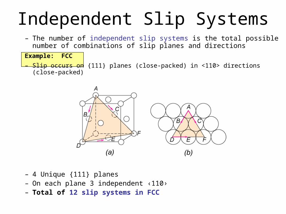
Independent Slip Systems– The number of independent slip systems is the total possible number
of combinations of slip planes and directions
Example: FCC
– Slip occurs on {111} planes (close-packed) in <110> directions (close-packed)
– 4 Unique {111} planes– On each plane 3 independent ‹110›– Total of 12 slip systems in FCC

Slip Systems
• Some slip systems in BCC are only activated at high temperatures• BCC and FCC have many possible slip systems – ductile materials• HCP: Less possible slip systems – brittle material

Stress and Dislocation Motion• Crystals slip due to a resolved shear stress, R. • Applied tension can produce such a stress.
slip plane
normal, ns
Resolved shear stress: R =Fs/As
slip
directi
on
AS
R
R
FS
slip
directi
on
Relation between and R
R =FS /AS
Fcos A/cos
F
FS
nS
AS
A
Applied tensile stress: = F/A
slip
directi
on
FA
F
coscosR

• Condition for dislocation motion: CRSS R• Crystal orientation can make it easy or hard to move dislocation
10-4 GPa to 10-2 GPa
typically
coscosR
Critical Resolved Shear Stress
maximum at = = 45º
R = 0
=90°
R = /2=45°=45°
R = 0
=90°
Schmid’s Law
Schmid Factor

Ex: Deformation of single crystal
So the applied stress of 6500 psi will not cause the crystal to yield.
cos cos 6500 psi
=35°
=60°
(6500 psi) (cos35)(cos60)
(6500 psi) (0.41)
2662 psi crss 3000 psi
crss = 3000 psi
a) Will the single crystal yield? b) If not, what stress is needed?
= 6500 psi
Adapted from Fig. 7.7, Callister 7e.

Ex: Deformation of single crystal
psi 732541.0
psi 3000
coscoscrss
y
What stress is necessary (i.e., what is the yield stress, y)?
)41.0(cos cos psi 3000crss yy
psi 7325 y
So for deformation to occur the applied stress must be greater than or equal to the yield stress