![THE INSANITY DEFENCE INTHE CRIMINAL LAWS …law.nus.edu.sg/sjls/articles/SJLS-Dec-2008-241.pdf · Singapore Journal of Legal Studies [2008] 241–263 THE INSANITY DEFENCE INTHE CRIMINAL](https://static.fdocuments.net/doc/165x107/5b894dad7f8b9aa81a8c2864/the-insanity-defence-inthe-criminal-laws-lawnusedusgsjlsarticlessjls-dec-2008-241pdf.jpg)
Singapore Civil Defence Force - scdf.gov.sg · 2 The Singapore Fire Safety Engineering Guidelines...
88
Singapore Civil Defence Force Singapore Fire Safety Engineering Guidelines 2015
Transcript of Singapore Civil Defence Force - scdf.gov.sg · 2 The Singapore Fire Safety Engineering Guidelines...

Singapore Civil Defence Force
Singapore Fire Safety Engineering Guidelines 2015

1
All rights reserved. No part of this document may be reproduced, stored in a retrieval system, or transmitted in any form or by means, electronic, mechanical, photocopying, recording or otherwise, without prior permission of the Singapore Civil Defence Force.

2
The Singapore Fire Safety Engineering Guidelines Committee
Chairman Assistant Commissioner Christopher Tan Singapore Civil Defence Force Deputy Chairmen Mr. Heng Chai Liang Singapore Civil Defence Force Secretary Maj Tong Hong Haey Singapore Civil Defence Force Editor Mr. Nicholas Lee Singapore Civil Defence Force Members Er. Shyam Dayanandan Institution of Engineers, Singapore
(IES)/C2D
Mr. Bryan Chin Association of Consulting Engineers Singapore (ACES)/AECOM
Mr. Zach Liew Institution of Fire Engineers (IFE) Singapore / Weil Singapore
Mr. Liew Kim Hoe Society of Fire Protection Engineers (SFPE) Singapore/LKH Fire
Er. Henry Ho Ignesis
Miss Ruth Wong Arup Singapore
Er. Victor Ho Hilt
Er. Yeo Swee Khiank Sereca Fire
Maj Chong Kim Yuan Singapore Civil Defence Force
Maj Jeffrey Ng Singapore Civil Defence Force
Dr Amer Magrabi Lote Consulting

3
CONTENTS
PART 1 Chapter 1 1.0 Introduction 8 1.1 Regulatory Framework 9 1.2 Definitions 11 Chapter 2 2.0 Fire Scenarios 15 2.1 Base Case 15 2.2 Sensitivity Studies 15 2.2.1 Buoyancy Test 15 2.2.2 Wind Effects 15 2.2.3 Fan efficiency 16 2.2.4 Increase in fire growth rate 16 2.2.5 Fire Blocks Exit / Exit Unavailable 16 2.2.6 Delay in detection time 16 2.2.7 Smouldering Fire 16 Chapter 3 3.0 Available Safe Egress Time (ASET) 17 3.1 Fire Hazards 17 3.2 Design Fire 17 3.2.(a) Pre-Flashover Fires 17 3.2.(a)(i) Type and nature of fuel 17 3.2.(a)(ii) Type of fire plumes 18 3.2.(a)(iii) Size/Growth Rate 19 3.2.(a)(iv) Method of determining fire size 19 3.2.(a)(v) Soot yield 20 3.2.(b) Post-Flashover (Used for structural
analysis) 21
3.2.(b)(i) Ventilation controlled 21 3.2.(b)(ii) Time temperature curve 22 3.3 Acceptance Criteria 23 3.3.(a) Temperature 23 3.3.(b) Radiation 23 3.3.(c) Visibility 23 3.3.(d) Fractional Effective Dose (FED) 23 3.4 Computational Fluid Dynamics (CFD)
modelling 24
3.4.(a) Define fire modelling goals 24 3.4 (b) Characterise the fire scenarios 24 3.4.(c) Documentation of output 29 3.5 Zone modelling 30 3.6 Approved zone modelling softwares 31

4
Chapter 4 4.0 Required Safe Egress Time (RSET) 32 4.1 Detection time 32 4.2 Notification Time 33 4.3 Pre-movement time 33 4.4 Movement time 34 4.5 Evacuation Models 38 4.6 Approved evacuation softwarers 39 Chapter 5 5.0 Marked up drawing 40 5.1 Architectural items in BP submissions 40 5.2 M & E items in the M&E Plan 41 5.3 Breakdown of M&E Plan 41 Chapter 6 6.0 Operations & Maintenance Manual 45 6.1 Cover page 45 6.2 Role & responsibilities of building operator 45 6.3 Future A/A 46 6.4 Affected areas with PB design 46 6.5 Identification of sub-systems 46 6.6 Maintenance plan 47 6.7 Documentation 47 6.8 Client briefing 47 6.9 Restrictions 47 6.10 Compensatory actions 47 6.11 Relevant circulars to be included 48 6.12 Credentials and Endorsement of FSE 48 Chapter 7 7.0 Peer Reviewer 49 7.1 Role of peer reviewer 49 7.2 Stage of involvement of peer reviewer 50 7.3 Modelling for Sensitivity Analysis 50 7.4 Dispute Resolution 50 Chapter 8 8.0 Registered Inspectors 51 8.1.1 When is a Registered Inspector Required? 51 8.1..1(a) Inspection Certificate FORM 1 51 8.1..1(b) Inspection Certificate FORM 2 51

5
PART 2 Chapter 9 9.0 Method of assessment for common
deviations 52
9.1 Common alternative solutions 52 9.1.1 Smoke Control [Enlarged smoke reservoir
(Area, length), or Atrium design (Width, area)] or Enlarged Fire Compartment
52
9.1.2 Extended 2-way travel distance or Excessive egress capacity
56
9.1.3 Internal discharge of exit staircase. 59 9.1.4 Insufficient set back distances from
notional boundary 63
9.1.5 Omission or Reduction of Fire rating of element of structure
64
9.1.6 Ductless Jet Fans (Non-compliance/s to FSR3:2008)
65
REFERENCES Annex A Methods of determining fire size Annex B Table of Fire Hazards Annex C Enclosure Fire Models Annex D Notification time Annex E Warning systems Annex F Pre-movement time Annex G Circular on Certification by QP for A/A Plans
involving PB Fire Safety Designs.
Annex H First Schedule of the Fire Safety (Registered Inspector) Regulations
Annex I Determining Load/Capacity Ratio for Structural Steel
TABLES Table 3.1 Design Fire Characteristics (Pre-Flashover) 20 Table 4.1 Constants relating to horizontal and stair travel 35 Table 4.2 Typical horizontal travel speeds for occupants
of different mobility levels 36
Table 4.3 Typical travel speeds along staircase for occupants of different mobility levels
36
Table
4.4 Boundary layer width used to determine effective width
37

6
Smoke Control [Enlarged smoke reservoir (Area, length), or Atrium design (Width, area)] or Enlarged Fire Compartment
Table 9.1 Design fires (sprinkler protected building) 54 Table 9.2 Fire size proposed by FSE based on DETACT
T2, FPETool or Firecalc 54
Table 9.3 Tenability Limits 54 Table 9.4 Acceptance Criteria 55 Table 9.5 Determining RSET 55 Table 9.6 Sensitivity Analysis (ASET/RSET ≥ 1.2) 55 Extended 2-way travel distance or
Inadequate egress capacity
Table 9.7 Design fires (sprinkler protected) 57 Table 9.8 Fire size proposed by FSE based on DETACT
T2, FPETool or Firecalc 58
Table 9.9 Tenability Limits 58 Table 9.10 Acceptance Criteria 58 Table 9.11 Determining RSET 58 Table 9.12 Sensitivity Analysis (ASET/RSET ≥ 1.2) 59 Internal discharge of exit staircase not
compliant with clause 2.3.3 (c) of the Fire Code.
Table 9.13 Design fires (sprinkler protected) 61 Table 9.14 Fire size proposed by FSE based on DETACT
T2, FPETool or Firecalc 61
Table 9.15 Tenability Limits 61 Table 9.16 Acceptance Criteria 61 Table 9.17 Determining RSET 62 Table 9.18 Sensitivity Analysis (ASET/RSET ≥ 1.2) 62 Insufficient set back distance from
notional boundary
Table 9.19 Design fires (sprinkler protected) 63 Table 9.20 Acceptance Criteria 63 Table 9.21 Sensitivity Analysis 64 Omission or Reduction of Fire rating of
element of structure
Table 9.22 Design fires (sprinkler protected) 65 Table 9.23 Acceptance Criteria 65

7
Ductless Jet Fans (Non-compliance/s to
FSR3:2008)
Table 9.24 Design fires (sprinkler protected) 66 Table 9.25 Acceptance Criteria 66 FIGURES Figure 1.1 Performance-Based Framework 10 Figure 3.1 Spill Plume 18 Figure 3.2 Tenability criteria to be sampled at 2.5m from
the finish floor level. 22
Figure 3.3 FED Sampling 25
Document History
Date Alterations
New Document
Effective from : N.A.

8
CHAPTER 1
1.0 INTRODUCTION
The Singapore Fire Safety Engineering Guidelines (SFEG) provides a means for Fire Safety Engineers (FSEs) to carry out Performance-Based (PB) designs to meet the objectives of the Fire Code (Code of Practice for Fire Precautions in Buildings). Where the design of fire safety works deviates from the prescribed or deemed-to-satisfy requirements stipulated in the Fire Code, the FSE may embark on an alternative solution ie PB approach to address these deviations. The SFEG therefore seeks to guide the FSEs and Peer Reviewers in preparing the relevant documents for submission to SCDF for approval. The documents to be prepared by the FSE include the (i) Fire Safety Engineering Design Brief (FEDB), (ii) Fire Safety Engineering Report (FER) and the (iii) Operations and Maintenance Manual (O&M), while that of Peer Reviewer includes the Peer Reviewer Report (PRR). This SFEG comprises two main parts, namely:
Part 1: PB regulatory framework, fire engineering design concepts, submission documentation requirements and the roles and responsibilities of the Fire Safety Engineers, Peer Reviewers and Registered Inspectors (FSE).
Part 2: Common alternative solutions from prescribed requirements and the general design approaches to address them.
While the latter part outlines the general design approaches to common alternative solutions from prescribed requirements, these are not mandated approaches and users are advised to apply them with care in view that buildings differ in terms of its design layout, fire load, occupant characteristics, etc. For such buildings where their design approach differs from that outlined in this document, the user is advised to engage SCDF early in establishing the design parameters.

9
Similarly, care must be exercised by the user when using any information in this document. SCDF shall not be held responsible for any wrongful design or misuse of information arising from the use of this document.
1.1 REGULATORY FRAMEWORK
.
1.1.1 A FSE is required to be appointed for the preparation of alternative solutions as part of the building plan submission to SCDF.
The FSE is required to produce a preliminary report - Fire Safety Engineering Design Brief (FEDB) to be submitted to SCDF for in-principle approval. The FEDB outlines the proposed fire safety engineering approach, methodology, and software tools etc. The FSE may consult SCDF on his FEDB proposal prior to its submission.
The FEDB will be assessed by SCDF. Upon the in-principle approval of the FEDB, the FSE can proceed to prepare the Fire Safety Engineering Report (FER) and the Operations and Maintenance Manual (O&M).
After the preparation of the above documents by the FSE, the Peer Reviewer (to be engaged by the owner) has to assess the documents and ensure that the alternative solution is incorporated in the Building and M&E plans. The Peer Reviewer shall produce a report of his assessment in a Peer Reviewer's report.
The Project QP is responsible for collating all the above documents for plans submission to SCDF. The alternative solution shall be endorsed by the FSE. QPs who are also qualified FSEs may endorse in the capacity of both the QP and the FSE.
The submitted plans and documents may be selected by SCDF for subsequent audit checks. Upon completion of the fire safety works, the owner is required to engage a Registered Inspector who is an FSE to inspect the performance-based aspects of the fire safety works. The flowchart below illustrates the process for the Performance-Based plan submission.

10
Figure 1.1 – The Performance-Based Framework For fire safety engineering designs involving structural solution, the owner has to engage a FSE who is also a Professional Engineer (PE) in the civil/structural engineering discipline. If the FSE is not a PE(civil/structural), the owner will need to engage a PE (civil/structural) to work together with the FSE. The Peer Reviewer would also need to be a PE in the civil/structural engineering discipline.
1.1.2 While Part two outlines possible design approaches to common alternative solutions from prescribed requirements, these are not mandated approaches and users are advised to apply them with care in view that buildings differ in terms of their design layout, fire load, occupant characteristics, etc. More unique buildings or spaces may require a more in-depth analysis and the user is advised to engage SCDF early in establishing design parameters.
1.1.3 Similarly, care must be exercised by the user when using any information in this document. SCDF shall not be held responsible for any wrongful design or misuse of information arising from the use of this document.

11
1.2 DEFINITIONS
1.2.1 The abbreviations listed in the following table are used in this Guidelines:-
Abbreviation
Abbreviation Definition † BS British Standard / BS EN
† CP Code of Practice † NFPA National Fire Protection Association
† SS Singapore Standard
† latest version shall be used. 1.2.2 Engineering solution for the fire safety works to satisfy any
fire performance requirements in the Fire Code, being a solution that is based on:
Alternative solution
(a) A deterministic or probabilistic analysis of fire scenarios or both types of analysis or
(b) A quantitative or qualitative assessment of design alternatives or both against the fire performance requirements in the Fire Code.
1.2.3 "Approved" means approved by the Relevant Authority
Approved
1.2.4 An area adequately separated from the rest of the building by fire resisting construction and evacuees from the rest of the building enter the area of refuge using an external corridor that links this area to the rest of the building. An area of refuge may also be an area in an adjoining building which is separated from the building under consideration by fire resisting construction and evacuees similarly enter this area of refuge using an external corridor.
Area of refuge[1]
1.2.5 An atrium within a building is a large open space created by
an opening, or a series of openings, in floor assemblies, thus connecting two or more storeys. Atrium is covered at the top and is used for purposes other than those associated with small shafts, such as for stairs, elevators and various services. The sides of the atrium may be open to all floors, to some of the floors, or closed to all or some floors by unrated or rated fire-resistance construction.
Atrium[1]

12
1.2.6 Available safe egress time (ASET). Time available for escape
for occupants. This is the calculated time interval between the time of ignition of a fire and the time at which conditions become such that the occupant is estimated to be incapacitated (ie, unable to take effective action to escape to a place of safety).
ASET[2]
1.2.7 Means exposure to fire for a time that includes fire growth, full
development, and decay in the absence of intervention or automatic suppression, beyond which the fire is no longer a threat to building elements intended to perform load-bearing or fire separation functions, or both.
Burnout[2]
1.2.8 Computational fluid dynamics (CFD). Computational method
that solves equations to represent the movement of fluids in an environment.
CFD[2]
1.2.9 Quantitative description of assumed fire characteristics within
the design scenario. Design fire[2]
1.2.10 Specific scenario on which a deterministic fire safety
engineering analysis is conducted. Design scenario[2]
1.2.11 Time interval between ignition of a fire and its detection by an
automatic or manual system or people. Detection time[2]
1.2.12 Time interval between the time of warning of a fire being
transmitted to the occupants and the time at which the occupants of a specified part of a building or all of the building are able to enter a place of safety.
Evacuation time[2]
1.2.13 Stage of fire development after a fire has reached its maximum
intensity and during which the heat release rate and the temperature of the fire are decreasing.
Fire decay[2]
1.2.14 Stage of fire development during which the heat release rate
and the temperature of the fire are increasing. Fire growth[2]
1.2.15 Fire load Quantity of heat which can be released by the
complete combustion of all the combustible materials in a volume, including the facings of all bounding surfaces (Joules).
Fire load[2]

13
1.2.16 Fire load energy density (FLED). Fire load per unit area (MJ/m2).
FLED[2]
1.2.17 Application of engineering methods based on scientific
principles to the development or assessment of designs in the built environment through the analysis of specific design scenarios or through the quantification of risk for a group of design scenarios.
Fire safety engineering[2]
1.2.18 Stage of fire transition to a state of total surface involvement in
a fire of combustible materials within an enclosure. Flashover[2]
1.2.19 Fractional effective dose (FED). The fraction of the dose (of
toxic gases or thermal effects) that would render a person of average susceptibility incapable of escape.
FED[2]
1.2.20 State of total involvement of combustible materials in a fire. Fully developed
fire[2] 1.2.21 Thermal energy produced by combustion of unit mass of a
given substance (kJ/g). Heat of
combustion[2] 1.2.22 Thermal energy produced by combustion (Joules). Heat release[2] 1.2.23 Heat release rate (HRR). Rate of thermal energy production
generated by combustion (kW or MW). HRR[2]
1.2.24 State of physical inability of occupants to accomplish a specific
task. Incapacitated[2]
1.2.25 Measure of the attenuation of a light beam passing through
smoke expressed as the logarithm to the base 10 of the opacity of smoke.
Optical density of smoke[2]
1.2.26 Ratio of incident light intensity to transmitted light intensity
through smoke under specified conditions. Opacity of
smoke[2] 1.2.27 Pre-movement time is the time interval between occupants
being informed to evacuate and the time in which they begin to travel to a safe location.
Pre-movement time

14
1.2.28 A Registered Inspector (R.I.) is a person who is registered under the Fire Safety Act to be qualified and competent to inspect fire safety works in buildings to ascertain the degree of compliance of fire safety requirements.
Registered Inspector
1.2.29 Time required for escape. This is the calculated time period required for the occupants to travel from their location at the time of fire ignition to a place of safety.
RSET[2]
1.2.30 Response Time Index (RTI). The measure of the reaction time
to a fire phenomenon of the sensing element of a fire safety device.
RTI[2]
1.2.31 Barrier that exhibits fire integrity, structural adequacy, thermal
insulation, or a combination of these for a period of time under specified conditions (in a fire resistance test).
Separating element[2]
1.2.32 Amount of smoke produced per unit time in a fire or fire test. Smoke
production rate[2] 1.2.33 Extinction area of smoke produced by a test specimen in a
given time period, divided by the mass lost from the test specimen in the same time period.
Specific extinction area[2]
1.2.34 In the context of the standard test for fire resistance, is the
time in minutes for which a prototype specimen has continued to carry its applied load within defined deflection limits.
Structural adequacy[2]
1.2.35 Flame spread away from the source of ignition across the
surface of a liquid or a solid.
Surface spread of flame[2]
1.2.36 The distance required to be traversed from the most remote point in any room or space to the edge of a door opening directly to
a) an exit staircase, or b) an exit passageway, or c) an open exterior space.
Travel distance[1]
1.2.37 Maximum distance at which an object of defined size,
brightness and contrast can be seen and recognised. Visibility[2]

15
CHAPTER 2
2.0 FIRE SCENARIOS
This guidelines sets out 7 fire scenarios and sensitivity analyses that the FSE is required to consider (qualitatively and/or quantitatively), depending on alternative solution(s) proposed. Refer to Part 2 of the SFEG to determine which fire scenarios to apply. These scenarios may not be exhaustive and that FSE would need to consider other scenarios where appropriate.
2.1 Design scenario representative of a typical fire within the occupancy considering its usage, population size, fuel load and ignition sources, ventilation, means of escape provisions, etc. All fire safety measures, including but not limited to, engineered smoke control systems, fire detection, means of escape, are assumed to be available and working as designed. Depending on the scope of the performance-based assessment, there could be more than one base case design fire scenario. The design fire locations shall be located at the most onerous/credible locations applicable to the Performance based design.
Base case
2.2 Sensitivity studies shall be conducted to test the robustness of the proposed design. These mandatory studies as described below (where applicable) may not be exhaustive and the FSE is to propose all relevant sensitivity analysis in the FEDB. SCDF may also request for other sensitivity analyses to be conducted, depending on the nature of the project and the extent of the alternative solutions.
Sensitivity Studies
2.2.1 Sensitivity Test 1 – Buoyancy
Buoyancy Test
(a) A 1 MW fire to test buoyancy for natural smoke control system.
2.2.2 Sensitivity Test 2 – Wind Effects
Wind Effects
(a) One side of vents (side with the most openings) is assumed to fail (ie vents modelled to be in closed position or subjected to wind effects that may negatively affect the vents) for natural smoke control system.

16
2.2.3 Sensitivity Test 3 – Fan efficiency
Fan failure
(a) To assume n-1 fans operation during fire mode, where n is the number of duty fans). (Not required if there are 2 or more standby fans)
(b) Alternatively, a 20% increase in fire size (peak HRR and fire perimeter) can be adopted in lieu of fan failure.
2.2.4 Sensitivity Test 4 – Increase in fire growth rate Increase in fire growth rate
(a) Fire is assumed to grow at a faster rate using t-squared fire e.g. from medium to fast or from fast to ultrafast.
2.2.5 Sensitivity Test 5 – Fire rendering an exit unusable
Fire Blocks Exit / Exit Unavailable
(a) A fire starts in an escape route and can potentially block an exit. Applies to premises/spaces where there are at least 2 exits.
(b) FSE should consider the largest exit or the most-utilized exit to be blocked.
(c) FSE would need to consider this if the alternative solution involves means of escape and/or engineered smoke control.
2.2.6 Sensitivity Test 6 – Delay in detection time Delay in detection time
(a) Failure of primary smoke/fire detection system (i.e. the first device that detects the smoke/fire).
2.2.7 Sensitivity Test 7 – Smouldering Fire
Smouldering Fire
(a) This scenario addresses the concern regarding a slow, smouldering fire that poses a threat to sleeping occupants Such fires may fill the rooms with toxic gases but may not be large enough to be detected by fire alarms or other occupants.
(b) Would typically be considered if the alternative solution involves sleeping occupancies.

17
CHAPTER 3
3.0 AVAILABLE SAFE EGRESS TIME (ASET)
Available safety egress time or ASET is the time available for escape for occupants. This is the calculated time interval between the time of ignition of a fire and the time at which conditions become untenable for the occupants to escape to a place of safety). As part of the performance based analysis, ASET is compared against Required Safe Egress Time (RSET) after applying the relevant safety factor. The factors that affect the ASET are discussed below. As not all input parameters can be accurately predicted, safety factors are applied to the analysis to cater to these uncertainties. Safety factors to be adopted are discussed in Chapter 9.
3.1 Fire hazards The FSE would need to identify all possible fire hazards within the scope of his/her study and determine which would be selected as design fires.
Fire hazards
3.2 Design Fires Depending on the scope and objectives of the fire engineering analysis, the design fires would generally fall into two main categories, which are pre and post flashover fires.
Design Fires
(a) Pre-Flashover fires are generally used for most design fires unless the design involves structural fire engineering analysis (where post flashover fires are used). For pre-flashover fire scenarios, the minimum details to be documented are as follows:
Pre-flashover fires
(i) Type and nature of fuel. The FSE would need to document the fuels present in the area of study. This includes the location, storage method, quantity or any other special characteristics/considerations.
Type and nature of fuel
18
(ii) Type of fire plumes
(1) Axis-symmetric plumes at the centre of room of fire origin - Such plumes produce lower smoke entrainment rates and higher smoke temperatures, and are generally applicable to all fire scenarios.
Axis-symmetric plumes
(2) Corner plumes at corner of room of fire origin Such plumes produce lower smoke entrainment rates and are applicable to corner spaces that are most remote from ventilation openings/exhaust points.
Corner plumes
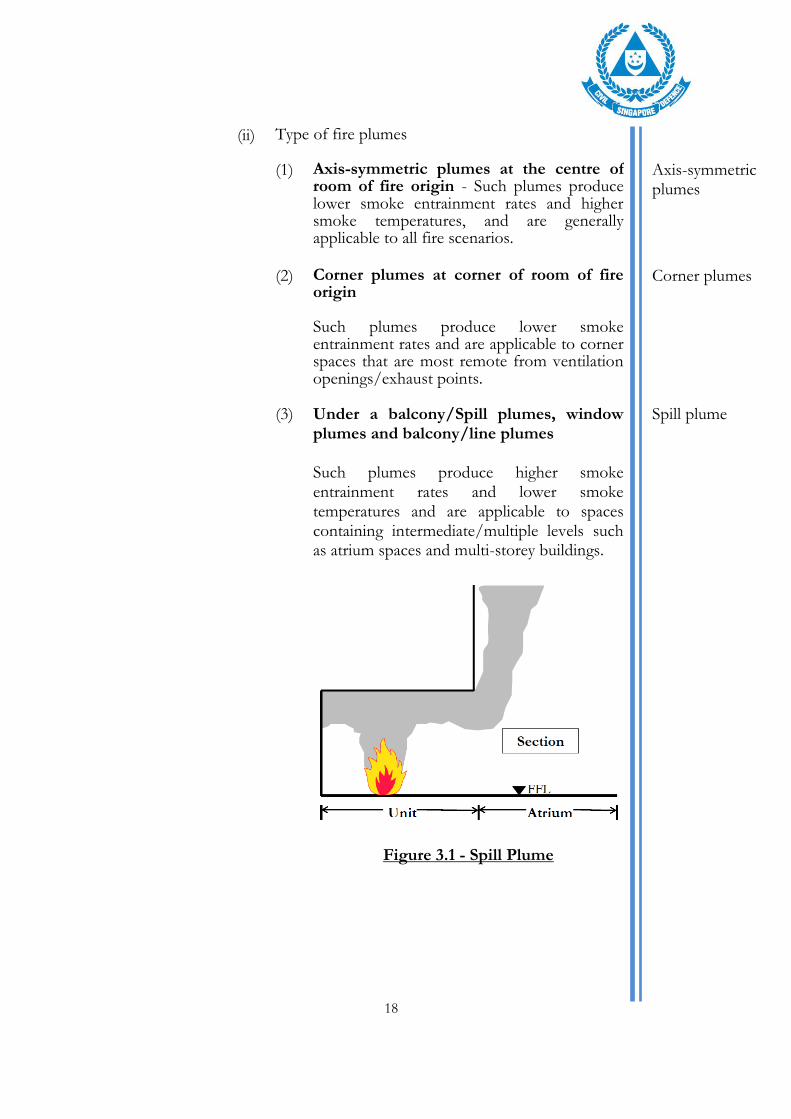
(3) Under a balcony/Spill plumes, window plumes and balcony/line plumes Such plumes produce higher smoke entrainment rates and lower smoke temperatures and are applicable to spaces containing intermediate/multiple levels such as atrium spaces and multi-storey buildings.
Figure 3.1 - Spill Plume
Spill plume
19
(iii) Size/growth rate (refer to Table 3.1)
The fire growth rate generally depends on the type of fuel load, which can be generally characterised by the building usage e.g. residential, commercial, etc. In the event a building has different fuel loads e.g., due to mixed occupancies, the FSE is advised to adopt a more conservative fire growth rate or seek a consultation with SCDF.
(iv) Method of determining fire size In most cases, the design fire size can be determined by the active fire protection system that is installed.
(1) If automatic sprinkler system is installed, fire size can be determined based on 2nd ring of sprinkler activation
Sprinkler protected premises
(2) If alternative water suppression systems are installed in lieu of sprinklers, fire size can be determined based on the following:
Alternative water suppression system
* Pre-action sprinklers Total time taken to activate (i) automatic fire detection system (e.g. smoke or heat detectors, flame detectors, air-sampling detectors, beam detectors, etc) including the time for the water to fill the pipework (water flow lag) and (ii) sprinkler system.
Pre-action sprinklers
* Deluge system Time taken to activate automatic fire detection system (e.g. smoke or heat detectors, flame detectors, beam detectors, etc) and for the water to be discharged.
Deluge systems
* Water monitor system Time taken to activate automatic fire detection system (e.g. flame detectors, etc) and for the water to be discharged.
Water monitor system

20
(3) If the building/space is not protected by
automatic sprinklers or other water-based fire protection systems, fire size to be determined by fuel load and ventilation area.
(4) Annex A gives a general guide to how fire size can be determined under various conditions.
(v) Soot yield FSE may adopt a soot yield, which refers to mass of soot generated during combustion divided by the mass loss of the test specimen, not lower than 0.1, unless he/she has justification to adopt other values.
Soot yield
Table 3.1 : Design Fire Characteristics (Pre-Flashover)
Location / Usage Fire growth rate
Areas of special/high hazard Industrial (performance requirements also provided under prescribed Code of Practice for Fire Precautions in Buildings 2013 FSR 4: 2008)
- Depends of fuel load burning
- Pool fires (e.g. fuel, etc) will be nearly instantaneous
- High rack storage potentially between Fast t2 to Ultrafast t2; potentially t3
Back of house areas / service areas
Depends of fuel load burning but generally Fast t2
Retail Fast t2
F&B (restaurants, food courts, coffee shops, hawker centres, fast food outlets)
Fast t2
Car parks Jet fan ductless system (performance requirements also provided under prescribed Code of Practice for Fire Precautions in Buildings 2013 FSR 3: 2008)
Fire growth rates are not prescribed as FSE to adopt the following fire sizes (or higher if deemed necessary by FSE) depending on the type of vehicles expected. With sprinkler protection, the total HRR for the following types of vehicles are as follows : 4 MW for cars/fork lifts 10 MW for goods vehicle 20 MW for buses/coaches

21
Table 3.1 : Design Fire Characteristics (Pre-Flashover)
Location / Usage Fire growth rate
Offices Fast t2
School classrooms, lecture halls, museums
Medium t2
Places of assembly (auditorium, theatres, performing arts)
Seating – Medium t2
Stage - Fast t2
If there is no control on the type of materials used for scenery, staging props (i.e. use of polystyrene, polyurethane, non-fire retardant drapes and curtains, etc), stage – Ultrafast t2
Exhibition (e.g. convention, expos, etc)
Fast or Ultrafast t2, depending on items exhibited
Recreational, amusement, night entertainment
Fast t2
If there is no control on the type of materials used for scenery, staging props (i.e. use of polystyrene, polyurethane, non-fire retardant drapes and curtains, etc), stage – Ultrafast t2
(b) Post-Flashover (Used for structural fire engineering
analysis)
Post flashover fires
(i) Ventilation Controlled In a post-flashover fire, the heat release rate can be limited by the amount of air that can enter the fire affected compartment. Ventilation controlled heat release rate, Qv : Qv = 1.5 x Av x h1/2 - - - - - - - - - - (3.1) Where: Av is total area of wall openings (m2) h is the weighted average height of openings (m)
Ventilation Controlled

22
(ii) Time-Temperature Curves (Flashover) References can also be made to other guidance documents including time-temperature curves (e.g. parametric, Swedish fire curves).
Time-Temperature Curves
3.3 Where the fire engineering assessment requires an assessment of human tenability to be made, the following limits of acceptability will apply:
Acceptance Criteria
Figure 3.2 Tenability criteria to be sampled at 2.5m from the finish floor level.
(a) Smoke Temperature – The average upper layer smoke temperature shall not exceed 200oC measured at 2.5m height from finished floor level and the average lower layer smoke temperature shall not exceed 60oC.
Temperature
(b) Radiation – Where occupants are expected to egress past a fire, the radiative heat flux shall not exceed 2.5 kW/m2.
Radiation
(c) Visibility at 2.5m above the floor level shall be greater than 10m.
Visibility
(d) Where the use of FED is to be used as an acceptance criterion, (for example, in situation where the ceiling is low and the use of acceptance criteria (a) to (c) is not feasible). Fractional Effective Dose (FED) for temperature and toxic gases shall not exceed 0.3.
Fractional Effective Dose

23
The use of FED as a criterion shall be subject to SCDF’s agreement. When proposed, the FSE would need to justify for FED criterion to be adopted in the design. Where FED analysis is permitted by SCDF, the guide for the sampling shall be as follows
(i) Methodology for FED determination The recommended methodology for FED determination is proposed below. Depending on the nature of the deviation, FSE may propose other methodologies for determining FED. FSE would need to consult SCDF before embarking on the FEDB.
Methodology for FED determination
(1) FED is sampled at the floor on fire and at all the entrances to places of safety (Eg: Doors to staircases/smoke stop lobby or doors to the external). These are areas where queuing is expected to take place. Snap shots of egress modelling would need to be submitted to SCDF to show when queuing has reached the peak. This is to justify areas where FED sampling will be carried out.
(2) Calculate or model the queuing domain and another 5 m away for the FED sampling.
Figure 3.3 - FED Sampling

24
(3) FED shall not be taken too near any air
intake openings. As a guide, this shall be at least 5 m away from any air intake openings.
(4) The sampling devices shall be spaced adequately close for better resolution. As a guide, the maximum placement distance between sampling devices (for measuring temperature, CO, CO2, O2, etc) for FED sampling shall not exceed 1m.
(5) Mark down on the plan and report where the FED sampling was taken.
3.4 Computational Fluid Dynamics (CFD) modelling With the advancement of performance-based fire engineering design, CFD is routinely used as an analysis tool as it possesses the ability to handle the complex geometries and characteristics of fire. In carrying out the CFD modelling, the following steps are recommended:
CFD modelling
(a) Define fire modelling goals To state clearly that the results of the CFD modelling shall be used to justify the performance based design.
Define fire modelling goals
(b) Characterise the fire scenarios Characterise the relevant fire scenarios from fire ignition, growth, detection, fire suppression and smoke control (if applicable). Selected scenarios should represent a complete set of fire conditions that are important to test the robustness of the proposed fire engineering design. These are discussed further below:
Characterising the fire scenarios

25
(i) Enclosure Define the enclosure being studied in the CFD modelling. The enclosure details should include the identity of the enclosures that belong in the fire model analysis, the physical dimensions of the enclosures included in the fire model, and the boundary conditions of each enclosure.
Enclosures
(ii) Fire Locations The fire locations used in the CFD modelling shall follow the proposed fire locations established from earlier sections of this guideline.
Fire Locations
(iii) Fire Characteristics The source fire is the critical input for the fire scenario and is often described as the “ignition source.” The source fire is typically characterised by a heat release rate though other important aspects include the physical dimensions of the burning object, its composition, and its behaviour when burning. The heat release rate may be specified as a continuous function of time (e.g. a t2 fire), or it may be an array of heat release rate and time data.
Fire Characteristics
(iv) Minimum details needed to describe the fire
Heat Release Rate (HRR)
HRR per unit area
Fire perimeter
Elevation from finished floor level
Soot yield
Heat of combustion
Toxic substances (for FED analysis)
Radiative heat flux (for FED analysis) The HRR chart is to be included in the FER to demonstrate the fire characteristics. The fire characteristics used in the CFD modelling shall follow the fire hazards identified and design fire(s) established in Table 3.1 of this guideline.
Minimum details needed
26
(v) Selecting the CFD software Given the availability of different CFD models, the FSE is responsible to assess its suitability for use in the fire engineering study. Whilst this set of guidelines is written predominantly for FDS considering its wide use in the fire engineering fraternity in Singapore, they also apply in a similar manner to other CFD models. The list of recognised CFD softwares is as follows:
Fire Dynamic Simulator (FDS)
Fluent
Phoenics Approval from SCDF is required if a CFD software, other than the above, is to be used. The use of any particular CFD software (including its version) must reflected in the FEDB.
Selecting the CFD software
(vi) Computational domain The computational domain should be as close as reasonably practicable to the actual enclosure. Simplification (such as modelling a slightly curved wall as a straight wall) can be accepted as long as it does not adversely affect outcome of the CFD modelling. Where inlet and/or exhaust vents are located at the domain boundaries, FSE has to include an additional 5m buffer outwards to account for the aerodynamics of the vents. Where wind effects are being modelled, the domain should be extended correspondingly to take this into consideration.
Computational domain

27
(vii) Boundary conditions Assumptions on the type of surface and material properties such as ambient temperature and properties of surfaces must be included. In situations where adiabatic/inert surfaces are assumed, justification on why such assumptions are considered appropriate must be included. Assumptions on ambient temperature & external wind effect for the areas being modelled must be included. As a guide, ambient temperature in air-conditioned spaces can be taken to be 24 oC while that of non air-conditioned spaces, 32 oC. Should other temperatures be adopted, FSE will provide the justifications.
Boundary conditions
(viii) Mesh and grid resolution The type of meshing i.e. structured vs unstructured and grid resolution can have significant impact on the accuracy of CFD computation, particularly for large eddy simulation models. In the case of FDS, FSE has to state whether single mesh or multi-mesh is to be used. Other information includes screenshots to illustrate the mesh set up, the mesh boundaries and the respective grid resolution. The recommended fine grid resolution should follow the FDS user guide. Fine grid shall extend at least 5m (in x, y and z direction) from the edge of burner in all directions. Progressive increase in grid resolution shall follow aspect ratio of 1:2.
Mesh and grid resolution
(ix) Duration of simulation For steady-state CFD modelling, the simulation should be iterated until the results converge. For transient CFD modelling, the simulation should continue until steady-state condition is observed.
Duration of simulation
28
As a guide the fire size should reach the design fire size. Temperature and visibility readings should be taken to demonstrate that the readings have stabilised.
(x) Smoke management systems Relevant smoke management system i.e. engineered smoke control system, smoke purging system or smoke vents must be included in the CFD modelling. For the case of engineered smoke control / purging system, the following information shall be provided
Ductwork layout (Deeper than 10% of floor height)
Beams (Deeper than 10% of floor height)
Extraction grilles
Make-up air paths
Heat/Smoke detectors (where applicable)
Sprinkler heads (where applicable)
Storage racks. FSE may assume a reasonable racking structure if the actual design is not known yet.
The actual system design layout must also be included for comparison with the CFD model. For the case of smoke vents, the following information shall be provided :
Smoke vents and replacement air vents (orientation and aerodynamic free area)
Smoke detectors (where applicable)
Sprinkler heads (where applicable) In the FER, the FSE is to include all relevant architectural plan & elevations for comparison with the CFD model.
Smoke management systems

29
FSE has to state the assumptions with respect to ramping up the operation of the smoke management system. As a general guide, the smoke management system is at 0% capacity at start of simulation. Upon its activation (to be based on smoke detectors/sprinklers depending on the system design), the system would reach full design capacity in less than 60s, as required in Clause 7.6.26 of the Fire Code.
(xi) Fire detection system Fire and smoke detectors must be included in the CFD model if they are provided to the actual spaces.
Fire detection system
(xii) Fire suppression systems It shall be assumed that the fire is maintained at the design fire size and not mitigated by the suppression system in the modelling study.
Fire Suppression Systems
(c) Documenting the output
Documentation
(i) FSE to include output quantities for visibility, temperature and velocity. Additional output quantities e.g. carbon monoxide, heat flux, FED may be required depending on the scope of the performance-based design.
(ii) In addition to slice files/snapshots, other output parameters such as radiometers, thermocouples, etc shall be included in the FER as the slice files may not capture all the relevant details.
Slice files
(iii) For slice parameter, FSE has to include slices in all three planes (x, y and z-planes).
(1) At least 3 slices of X-plane & Y-plane with one cut along the centreline of the fire origin. Include additional slices at critical areas in the model. More slices may be required if a spill plume forms part of the analysis.

30
(2) At least 2 slices of Z-plane at 1.7m (estimated human height level), and 2.5m above the finished floor level. Include additional slices at critical areas in the model. Where the mesh does not match, FSE shall provide slices at the next higher/available height (i.e. 1.8m and 2.6m).
(3) For the X, Y and Z planes, the slice/snapshot shall be taken at :
At 8 minutes
RSET
RSET with safety factor
Steady state (If it is earlier than RSET with safety factor)
Any other slices that SCDF or the FSE deems fit.
(iv) Include the following CFD results in the FER.
Heat Release Rate
Visibility readings
Temperature readings
FED (if applicable)
Visibility, temperature and FED readings should be taken at the reference height as defined under the tenability acceptance criteria.
3.5 Zone modelling Zone models can be adopted to determine ASET. However, the compartment size limits for the use of zone models shall be according to the maximum reservoir sizes stated in the Fire Code, or the size limits stipulated by the respective software user manual, whichever is lower. In projects where zone models are used to determine ASET, SCDF may still require the FSE to conduct CFD simulation.
Zone modelling

31
3.6 The list of approved zone modelling softwares are :
CFAST
Branzfire/B-Risk
Approved modelling software

32
CHAPTER 4
4.0 REQUIRED SAFE EGRESS TIME (RSET) Required safe egress time or RSET is the time required for escape. This is the calculated time required for occupants to travel from their location at the time of ignition of fire to a place of safety. The RSET would need to be less than the ASET, with relevant safety factors applied. RSET = (td + tn + tpre) + (ttrav and/or tflow) - - - - - - - - - - (4.1) where: td = detection time from deterministic modelling tn = time from detection to notification of occupants tpre = time from notification until evacuation begins ttrav = time spent moving toward a place of safety, and tflow = time spent in congestion controlled by flow characteristics
4.1 Detection time (td) Time interval between ignition of a fire and its detection by an automatic or manual system. The detection time shall be based on the activation of the 1st ring of the detector system. The following methods can be used to estimate the detection time (td):
Detection time
(a) Based on CFD modelling conducted with the detectors/sprinklers above a fire using approved fire models
(b) Based on Alpert’s[11] ceiling jet correlation.
(c) Based on zone models.
4.1.1 For automatic detection, the input parameters used in the modelling study shall be the same as the properties of the detectors/sprinklers used in the design as well as the layout of the detectors/sprinkler.
Automatic detection
(i) Response Time Index (RTI) of sprinkler/detector.
33
(ii) Activation temperature (Tact) of
sprinkler/detector.
(iii) C-factor for sprinklers.
(iv) Optical density at alarm for smoke detectors.
(v) Radial distances adopted shall be based on a code-compliant (SS CP 10 (Code of Practice for Installation and Servicing of Electrical Fire Alarm System)/SS CP 52 (Code of Practice For Automatic Fire Sprinkler System)/NFPA/etc) system design. For detection time, the radial distances may be based on first-ring activation of sprinklers/detectors.
Where there are no automatic fire detection systems installed, manual/human detection time can be estimated based on smoke layer height reaching 10% of the room height. FSEs are advised to consult SCDF before adopting this approach.
Manual/Human detection
4.2 Notification Time (tn) This is the time required for building management to confirm with DECAM companies whether the fire alarm is a false alarm or a confirmed fire and this time is taken to be 120 seconds. FSE to justify if other timings are adopted.
Notification Time
4.3 Pre-movement time (tpre) Pre-movement time is the time interval between occupants being informed to evacuate and the time in which they begin to travel to a safe location. Refer to Table F-1 in Annex F.
Pre-movement time
(a) The quantification of pre-movement time is highly
dependent on occupant behaviour and fire safety systems in place. The behaviour of escaping occupant depends on the following factors:
(i) Building characteristics (i.e. occupancy type, detection, alarm, fire safety management and building layout)

34
(ii) Occupant characteristics (occupant numbers, alertness and familiarity)
(iii) Exposure to fire effluent
(b) Annex F presents a more detailed explanation on some of these factors involved in estimating the pre-movement times. Any of the pre-movement times obtained from New Zealand document, C/VM22 in Table A6-1 can be used in the egress design and the FSE would need to justify his/her choice.
4.4 Movement time (ttrav or tflow)
The time taken by occupants to move to a place of safety is determined by the longer timing of:
The time taken to move to the doorway of the exit staircase (eg analysing egress from compartment/floor) or the final exit door at level one (analysing total building evacuation) (ttrav) , or
The flow time, (tflow) (i.e time taken for all the occupants to flow through a restriction, typically a doorway, when queuing is necessary).
Movement time
(a) Travel time (ttrav) Travel time (i) For horizontal travel, the travel time will be
calculated based on the estimated walking speed. Horizontal travel speed will be calculated using equation (4.2).
S = k – akD - - - - - - - - - - (4.2)
Where
S is horizontal travel speed (m/s)
k is 1.4 for horizontal travel
a is 0.266
D is the occupant density of the affected space (persons/m2)
Horizontal travel

35
Horizontal travel time is then calculated using equation (4.3) below: ttrav = Ltrav / S - - - - - - - - - - (4.3)
Where Ltrav is the required travel distance (m)
(ii) For vertical travel, the values used for the factor k are a function of the stair riser and thread as shown in Table 4.2.
Vertical travel
Table 4.1: Constants relating to horizontal and stair travel (extracted from PD-7974 Part 6)
Exit route element k Speed
Corridor, aisle, ramp, doorway 1.40 1.19
Riser (mm) Tread (mm)
191 254 1.00 0.85
178 279 1.08 0.95
165 305 1.16 1.00
165 330 1.23 1.05
(iii) Table 4.3 and 4.4 also lists some typical travel
speeds for occupants of different levels of mobility, both for horizontal travel as well as vertical travel via staircase.
Different levels of mobility.

36
Table 4.2: Typical horizontal travel speeds for occupants of different mobility levels
Table 4.3: Typical travel speeds along staircase for occupants of different mobility levels
37
(b) Flow time (tflow) Flow time (i) The flow rate of persons passing through a
particular point along an exit route can be calculated using equation (4.4):
Fc = (1-aD)kDWe - - - - - - - - - - (4.4)
Where: Fc is the calculated flow rate (persons/s) D is the occupant density near flow constriction (persons/m2) We is the effective width of component being traversed (m) k and a are defined in equation (4.2) above.
Flow rates
(ii) The effective width for various exit route elements can be determined from Table 4.4, by subtracting the boundary layer on each side from the measured exit width. For doorways that are not mechanically held open, a maximum flow rate of 50 persons/min/door leaf is recommended for design.
Effective width
Table 4.4: Boundary layer width used to determine effective width
SFPE Handbook of Fire Protection Engineering, edition 3 (Table 3.14.1)

38
(iii) For flows through a doorway, the occupant density to be used in equation (4.5) can be estimated to be 1.9 persons/m2. This value can be referred from the New Zealand Document C/VM2[2] document.
Flow through doorway
The flow time can then be determined from the flow rate using equation (4.5): tflow = Number of occupants / Fc - - - - - - - - (4.5)
4.5 Evacuation Models Evacuation modelling is increasingly becoming a part of performance-based analyses to assess the level of life safety provided in buildings. In some cases, FSEs use hand calculations to assess life safety, and in others, evacuation models are used. Hand calculations may be allowed for occupancies with a lower occupant loading, such as factories and warehouses. However, for buildings/spaces with large occupant loads such as in shopping centres, exhibition halls, offices and places of public resort and the like, evacuation modelling would be required by SCDF. If unsure, FSE is encouraged to consult SCDF before finalising the FEDB.
Evacuation Models
(a) Hand calculations usually adopt the equations given in the Emergency Movement Chapter of the Society of Fire Protection Engineers (SFPE) Handbook[14] to calculate mass flow evacuation from any height of building. The occupants are assumed to be standing at the doorway to the stair on each floor as soon as the evacuation begins. The calculation focuses mainly on points of constriction throughout the building (egress doorways) and calculates the time for the occupants to flow past these points and to the outside.
Hand calculations
39
(b) Validation of models If the proposed software is new or has limited application in Singapore, SCDF may require validation of the software before being allowed for use. The current ways of validating evacuation models are:
Validation of models
(i) validation against code requirements; (e.g. NFPA 130);
(ii) validation against fire drills or other people movement experiments/trials;
(iii) validation against literature on past evacuation experiments (flow rates, etc);
(iv) validation against other models and third party validation.
4.6 The list of approved evacuation softwares are :
Simulation of Transient Evacuation and Pedestrian Movements (STEPS)
Pathfinder
Simulex
Exodus
Approved evacuation softwares

40
CHAPTER 5
5.0 MARKED UP DRAWINGS
Fire safety provisions that form part of the performance based design strategy should be highlighted on the respective architectural or Building Plan (BP) and/or Mechanical and Electrical (M&E) plans that are submitted to SCDF for approval. This is to facilitate the audit and documentation of the performance based strategy by SCDF. These fire safety provisions to be included in the plan submissions fall into these broad categories:
5.1 BP submission The following information to be included in this category include (but not limited to)
Architectural items in BP submissions
(a) Table/summary of architectural alternative solutions.
(b) Area/floor(s) under the performance based study to be indicated (via clouding or other means)
(c) Mark out non-compliances (eg: length the path of extended travel distance/s)
(d) Details of occupant loading and egress capacity for all affected floors.
(e) Fire shutters, smoke curtains/barriers
(f) Floor to floor height
(g) Compartmentation lines, including fire resistance rating.
(h) Natural vent openings and their sizes/areas (m2).
(i) Replacement air doors/windows/vents and their sizes/areas (m2).
(j) Waivers and consultations applied for and summary of the waiver decision (if any)

41
5.2 M&E Plan submission The following information to be included this category include (but not limited to)
M & E items in the M&E Plan
submissions
(a) Table/summary of M & E alternative solutions
(b) Smoke control system detail
(c) Area/floor(s) under the performance based study to be indicated (via clouding or other means)
(d) Smoke zones
(e) Smoke curtains/barriers
(f) Waivers and consultations applied for and summary of the waiver decision (if any)
5.3 The mark ups for M&E plan can be further broken down to the following :
Breakdown of M&E Plan
(a) Mechanical ventilation
Mechanical ventilation
(i) Fan capacity and to also indicate duty and standby fans.
(ii) Extract points
(iii) Replacement air doors/windows/vents and their sizes/areas (m2).
(iv) Demarcation of smoke zones.
(b) Fire protection
Fire protection
(i) Sprinkler/Water monitor coverage, etc
(ii) Sprinkler details (Discharge rate, Response Time Index, etc)

42
5.4 Reference Drawings for FEDB & FER Submissions Reference drawings are to be submitted at the FEDB and FER stages. These drawings should capture all alternative solutions and fire safety provisions that support the performance based design. It should also capture all the elements of the FSE’s trial design concept in their alternative design. Reference drawings would be used by SCDF when deliberating on the performance based fire safety issues for FEDB and FER approval.
Reference Drawings for FEDB & FER Submissions
5.5 Unlike the drawings for the formal building plan/M&E plan submission, the reference drawings need not be broken up into the architectural and M&E sets. However, the reference set must include all performance based floors and relevant elevations/sections. Items to be marked up on the reference plans include (but not limited to):
(a) Details of all alternative solutions (alternative solutions are to be numbered).
(b) Design fires. To mark up location and fire size. All design fires to be numbered. The reference drawings should also include sensitivity studies.
(c) Floor height/s
(d) Fire shutters and smoke curtains
(e) Compartment walls/boundaries, including fire resistance rating.
(f) Occupant Loading and Egress Capacity
(g) If they are alternative solutions and form part of the performance based design solution, the reference drawings should show :
(i) How reservoir length/area is measured.
(ii) Paths of extended travel distance

43
(iii) Paths of extended travel distance for internal discharge
(h) Mechanical ventilation fans and ductwork. To indicate how many duty fans operate during fire emergency and how many standby fans are there.
(i) Differentiate separate smoke control zones
(j) Smoke control matrix
(k) Path(s) of replacement air. To also show openings on the elevation.
(l) Path(s) for natural smoke exhaust. To also show openings on the elevation.
(m) Sprinkler details (E.g. : temperature rating / RTI / Discharge density)
(n) Beam detector location, if any
5.6 For drawings to be submitted at the Building Plan approval stage (together with the FER, Peer Reviewer Report & O&M Manual) the submission could contain both (1) the formal BP/M&E set of drawings for approval and the (2) set of reference drawings. The design team may choose to combine both sets into a single set of drawings that would be used for approval and presentation/deliberation by SCDF. Reference drawings must be endorsed by the FSE.
5.7 The above mark ups need not be in a single drawing as long as all relevant details are captured.
5.8 Other administrative requirements include :
(a) To indicate : FEDB Reference Drawing or “FER Reference Drawing” at the top right hand corner (if the formal submission drawings are separate from the reference drawings)
(b) Soft copies of reference drawings submitted shall be in pdf format

44
(c) Waiver of fire safety requirements applied for and
summary of the waiver decision(s) (if any)
(d) Consultation numbers if QP/FSE has sought consultation
(e) Be dated according to when the reference drawings were submitted to SCDF. This is to eliminate confusion if multiple versions of the drawings are submitted
(f) Project title block

45
CHAPTER 6
6.0 OPERATIONS & MAINTENANCE MANUAL
The O&M manual explains what the building operator and fire safety manager (FSM) should do to maintain and operate the fire safety systems. It also gives instructions to the building operator on the restrictions placed on the contents in the building e.g. daily operations, addition & alteration works to the building and change of use of the building, based on FSE's assumptions and design considerations. The O&M manual can also be used to communicate to the tenants and occupants about these restrictions and their responsibilities. It can also be used as a guide for future renovations and changes to the building. The updated O&M Manual must be given to the owner/client after the performance based audit is closed (see para 6.8).
6.1 The cover page shall clearly state that the O&M Manual is prepared for :
a) Building Owner/Managing Committee/Agent b) Facilities Director/Manager c) Fire Safety Manager / Company Emergency Response
Team (CERT)
Cover Page
6.2 Role & responsibilities of building operator State the role and responsibilities of the building operator and fire safety manager (FSM), if applicable, in ensuring that the components of the performance-based design are in place, operating properly and a label, “This building has performance-based fire safety design” to be affixed to the main fire alarm panel or zone chart. This is to alert or remind the building owner and QPs that this is a performance-based building and the Operations and Maintenance Manual must be understood before undertaking any addition and alteration works.
Role & responsibilities of building operator

46
Design considerations with potential impact to life safety or building operations shall be stipulated for the building owner to adopt. Amendments or deviations from the requirements in the operations and maintenance manual may affect the performance-based analysis and solutions.
6.3 Future Addition & Alteration (A/A) Works State what the building operator needs to do with respect to compliance to the existing Fire Safety Design if there are A&A Works in the future. A letter of no objection from the FSE or QP shall be required as part of the QP’s submission if the A/A works clearly do not affect the Performance-Based (PB) design of the building. See SCDF circular on “Certification by QP for A/A Plans Involving Performance-Based Fire Safety Designs” dated 10th October 2013 (Annex G)
Future A/A
6.4 Affected Areas with PB design The scope and floor plan of the affected area(s) with PB design shall be clearly shown and demarcated from the other areas that were designed based on prescribed code requirements.
Affected areas with PB design
6.5 Identification of sub-systems Identify and describe the relevant sub-systems (sequencing, critical design features) for the particular project and their interaction with each other. Some examples are:
a) Fire detection b) Fire protection c) Emergency warning d) Occupant evacuation e) Smoke management f) Electromagnetic lock
The above-mentioned sub-systems shall be included for inspection and maintenance as part of the process of obtaining Fire Certificate (FC) for the building. The O&M manual shall specify that the building operator is advised to inform the QP that this is a performance-based design building.
Identification of sub-systems

47
6.6 Maintenance plan Commissioning, maintenance and subsequent yearly testing and inspection plans shall be developed in accordance with the minimum requirements of the relevant codes of practice and manufacturer’s guidelines. If the performance based design requires a higher level of servicing such as higher frequency of maintenance, the FSE shall highlight the additional requirements in the O&M Manual.
Maintenance plan
6.7 Documentation of inspections/testing and their results shall be maintained with the building records. FSE shall include in the need to maintain inspection records.
Documentation
6.8 FSEs would need to conduct a briefing to the client/end user/building operator on all performance-based issues when the Fire Engineering Report is cleared. Official letters must be submitted to SCDF from the client stating that they have been briefed by the FSE and received the O&M Manual.
Client briefing
6.9 Restrictions List the restrictions placed on the building operations. These restrictions may include content in the building, building use/purpose/activity and occupancy, and reliability and maintenance of systems. For example :
a) Storage height b) Storage content c) Limitation on transport vehicle in warehouse d) Commercial activity in certain parts of the building e) Activity with potential change in occupant type
Restrictions
6.10 Compensatory actions Highlight compensatory actions that must be taken if a fire protection system is impaired (e.g. requires servicing or maintenance, causing it to be out of service temporarily) or removed from service. Any impairment or removal of fire protection system may be subject to total review of the fire safety systems by a FSE.
Compensatory actions

48
6.11 Relevant circulars FSE to include all relevant circulars affecting buildings with performance-based design. These include :
a) Certification by QP for A/A plans involving Performance-Based fire safety designs dated 18 Oct 2013 and
b) Identification of buildings with Performance-Based fire safety designs & certification by QP for A/A plans dated 5th June 2012
Relevant circulars
6.12 Credentials and Endorsement of FSE Include name, credentials and endorsement of the FSE who prepared the manual.
Credentials and Endorsement of FSE
49
CHAPTER 7
7.0 Peer Reviewer
The Peer Reviewer is another FSE, engaged by the building
developer/owner, who is responsible to check the adequacy
of the performance-based solution prepared by the FSE for
the particular project. The Peer Reviewer is required to
submit an official report (Peer Reviewer's Report) to SCDF
detailing his comments on the FSE's work. It is expected of
the Peer Reviewer to conduct a separate fire or evacuation
modelling to verify the design solution proposed by the FSE,
preferably using different software from that used by the
FSE.
In addition, the Peer Reviewer should comment on the
assumptions, fire safety engineering approach, methodology,
design parameters and software tools in the FER, etc
proposed by the FSE. The Peer Reviewer will also need to
furnish a Peer Reviewer declaration form together with the
Peer Reviewer's Report in the submission to SCDF.
The Peer Reviewer shall have no vested interest in the project
that is being reviewed, or any involvement thereof which may
be construed as a conflict of interest. As the peer reviewer
must be independent from the project FSE, the peer reviewer
should only be involved after the FSE had completed the
FER.
7.1 Role of Peer Reviewer Role of Peer Reviewer
(a) To review the robustness of the fire engineering study by the FSE, including reviewing design objectives, assumptions, methodologies, input parameters used by FSE.
(b) To review the fire engineering analysis performed for consistency between FEDB and FER.

50
(c) To perform independent sensitivity analysis (e.g. increasing fire size, increasing soot yield, increasing fire perimeter to reduce buoyancy, introduce MV failure, reduce walking speed, reduce awareness factor of exits, increase pre-movement times, etc)
(d) Peer Reviewers should not be restricted or influenced in their design preference. Peer reviewers may determine their own technical approaches and acceptance criteria which may be different from the FSEs.
7.2 Stage of involvement of Peer Reviewer
Stage of involvement of Peer Reviewer. (a) Peer Reviewers shall only be involved after the FSE had
completed the FER in order to maintain the level of independency.
7.3 Modelling for Sensitivity Analysis Modelling for Sensitivity Analysis
(a) Peer Reviewers shall use a validated modelling tool to conduct independent assessment. The validated modelling tool shall preferably be different from that used by the FSE. In the event that the Peer Reviewer uses the same modelling tool, the required pre-processing for setting up the model must be independently performed by the Peer Reviewer.
7.4 Dispute Resolution Dispute Resolution
(a) Any dispute or difference in opinion (e.g. technical approaches, acceptance criteria, etc.) arising between the FSE and Peer Reviewer should be discussed and resolved between the FSE and Peer Reviewer. In the event that a common resolution cannot be reached, the concerns must be brought to SCDF for resolution.

51
CHAPTER 8
8.0 8.1.1
REGISTERED INSPECTOR (FSE)
When are Registered Inspectors (FSE) required? For projects containing alternative solutions, the areas under the performance-based assessment has to be inspected by a SCDF registered RI, who must also be a FSE. His scope of work involves the checking of on-site installation of fire safety engineering works for compliance with the approved PB plans, FER and Operations & Maintenance Manual and to surface irregularities to SCDF.
RI FSE
(a) Performance-based projects would require RI (FSE), RI (Arch) and RI(M&E). If the RI(Arch) is also a FSE, he/she can be responsible for both the fire safety works listed in Part I of the First Schedule of the Fire Safety (Registered Inspector) Regulations and the performance-based works of the project. See Annex H.
RI (Arch)
(b) If the RI(M&E) is also a FSE, he/she can be responsible for both the fire safety works listed in Part II of the First Schedule of the Fire Safety (Registered Inspector) Regulations and the performance-based works of the project. See Annex H.
RI (M&E)

52
CHAPTER 9
9.0
9.1
METHODS OF ASSESSMENT FOR COMMON ALTERNATIVE SOLUTIONS This chapter recommends methods to assess common alternative solutions. It covers:
a. Objectives to be achieved b. Design fire scenarios c. Tenability limits d. Acceptance criteria e. Sensitivity analysis
Where a FSE is assessing alternative solutions that are not in this list, it is recommended that the FSE consults SCDF before embarking on the FEDB. The methods of assessment listed serve as a guide and the FSE shall still be responsible for the design solution.
Common alternative solutions
9.1.1 EXAMPLE 1
Smoke Control [Enlarged smoke reservoir (Area, length), or Atrium design (Width, area)] or Enlarged Fire Compartment
Smoke Control [Enlarged smoke reservoir (Area, length), or Atrium design (Width, area)] or Enlarged Fire Compartment
(a) Root objectives The root objectives are :
(i) R2.1 - Occupants must be able to escape to a safe place, directly or through a protected exit, before untenable conditions are reached during a fire emergency.
(ii) R2.2 - Fire-fighters must be provided with adequate means of access for fire fighting and rescue operations within the building.
(iii) R7.1 - Maintain tenable conditions for evacuation of occupants and protect them from injury arising from the effects of fire.
53
(iv) R7.2 - Provide smoke management in the building for firefighting operations.
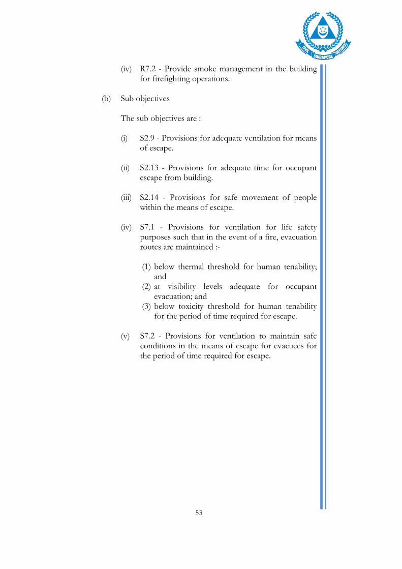
(b) Sub objectives The sub objectives are :
(i) S2.9 - Provisions for adequate ventilation for means of escape.
(ii) S2.13 - Provisions for adequate time for occupant escape from building.
(iii) S2.14 - Provisions for safe movement of people within the means of escape.
(iv) S7.1 - Provisions for ventilation for life safety purposes such that in the event of a fire, evacuation routes are maintained :-
(1) below thermal threshold for human tenability; and
(2) at visibility levels adequate for occupant evacuation; and
(3) below toxicity threshold for human tenability for the period of time required for escape.
(v) S7.2 - Provisions for ventilation to maintain safe conditions in the means of escape for evacuees for the period of time required for escape.

54
Table 9.1 – Design fires (sprinkler protected building)
Usage Location
Size
Remarks
Factory / warehouse / large space or compartment
Centre of space or credible location
Proposed by FSE (E.g. use of 2nd ring sprinkler activation)
In-rack Proposed by FSE
Loading / Unloading bay
10 MW truck fire (as prescribed by the fire code) or higher (if deemed necessary by FSE)
Atrium Centre Proposed by FSE Axis-Symmetric plume
Shop/unit 5MW (as prescribed by the fire code) or other appropriate fire size as proposed by FSE.
Axis-Symmetric plume or spill plume.
Table 9.2 – Fire size proposed by FSE based on DETACT T2, FPETool or Firecalc
Usage
Growth rate
Remarks
Factory/warehouse Ultra fast 2nd ring sprinkler activation
Factory in-(rack sprinklers)
Ultrafast Next higher level of sprinkler activation
Usage other than industrial.
Fast/Ultrafast 2nd ring sprinkler activate.
Table 9.3 – Tenability Limits
Tenability Criteria
Smoke layer 2.5m above relevant Finished Floor Level (FFL)
Visibility > 10m
Temperature < 200oC
Smoke layer drops below 2.5m above relevant FFL
Temperature < 60oC
55
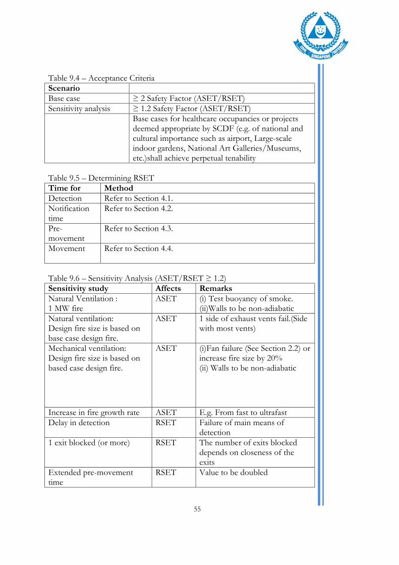
Table 9.4 – Acceptance Criteria
Scenario
Base case ≥ 2 Safety Factor (ASET/RSET) Sensitivity analysis ≥ 1.2 Safety Factor (ASET/RSET)
Base cases for healthcare occupancies or projects deemed appropriate by SCDF (e.g. of national and cultural importance such as airport, Large-scale indoor gardens, National Art Galleries/Museums, etc.)shall achieve perpetual tenability
Table 9.5 – Determining RSET
Time for Method
Detection Refer to Section 4.1.
Notification time
Refer to Section 4.2.
Pre-movement
Refer to Section 4.3.
Movement Refer to Section 4.4.
Table 9.6 – Sensitivity Analysis (ASET/RSET ≥ 1.2)
Sensitivity study Affects Remarks
Natural Ventilation : 1 MW fire
ASET (i) Test buoyancy of smoke. (ii)Walls to be non-adiabatic
Natural ventilation: Design fire size is based on base case design fire.
ASET 1 side of exhaust vents fail.(Side with most vents)
Mechanical ventilation: Design fire size is based on based case design fire.
ASET (i)Fan failure (See Section 2.2) or increase fire size by 20% (ii) Walls to be non-adiabatic
Increase in fire growth rate ASET E.g. From fast to ultrafast
Delay in detection RSET Failure of main means of detection
1 exit blocked (or more) RSET The number of exits blocked depends on closeness of the exits
Extended pre-movement time
RSET Value to be doubled

56
9.1.2 EXAMPLE 2
Extended 2-way travel distance or Inadequate egress capacity
Extended 2-way travel distance or Inadequate egress capacity (a) Root objectives
The root objectives are :
(i) R2.1 - Occupants must be able to escape to a safe place, directly or through a protected exit, before untenable conditions are reached during a fire emergency.
(ii) R2.2 - Fire-fighters must be provided with adequate means of access for fire fighting and rescue operations within the building.
(iii) R7.1 - Maintain tenable conditions for evacuation of occupants and protect them from injury arising from the effects of fire.
(iv) R7.2 - Provide smoke management in the building for firefighting operations.
(b) Sub objectives The sub objectives are :
(i) S2.9 - Provisions for adequate ventilation for means of escape.
(ii) S2.13 - Provisions for adequate time for occupant escape from building.
(iii) S2.14 - Provisions for safe movement of people within the means of escape.
(iv) S7.1 - Provisions for ventilation for life safety purposes such that in the event of a fire, evacuation routes are maintained :-
57
(1) below thermal threshold for human tenability; and (2) at visibility levels adequate for occupant evacuation; and (3) below toxicity threshold for human tenability for the period of time required for escape.
(v) S7.2 - Provisions for ventilation to maintain safe conditions in the means of escape for evacuees for the period of time required for escape.
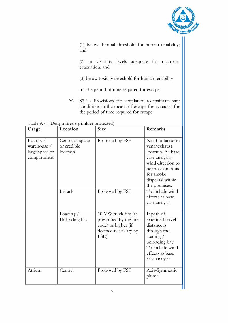
Table 9.7 – Design fires (sprinkler protected)
Usage Location
Size
Remarks
Factory / warehouse / large space or compartment
Centre of space or credible location
Proposed by FSE Need to factor in vent/exhaust location. As base case analysis, wind direction to be most onerous for smoke dispersal within the premises.
In-rack Proposed by FSE To include wind effects as base case analysis
Loading / Unloading bay
10 MW truck fire (as prescribed by the fire code) or higher (if deemed necessary by FSE)
If path of extended travel distance is through the loading / unloading bay. To include wind effects as base case analysis
Atrium Centre Proposed by FSE Axis-Symmetric plume

58
Shop/unit 5MW (as prescribed by the fire code) or other appropriate fire size as proposed by FSE
Axis-Symmetric plume or spill plume
Table 9.8 – Fire size proposed by FSE based on DETACT T2, FPETool or Firecalc
Usage
Growth rate
Remarks
Factory/warehouse Ultrafast 2nd ring sprinkler activation
Factory in-(rack sprinklers)
Ultrafast Next higher level of sprinkler activation
Usage other than industrial.
Fast/Ultrafast 2nd ring sprinkler activation
Table 9.9 – Tenability Limits
Tenability Criteria
Smoke layer 2.5m above relevant FFL Visibility > 10m Temperature < 200oC
Smoke layer drops below 2.5m above relevant FFL
Temperature < 60oC
Table 9.10 – Acceptance Criteria
Scenario
Base case ≥ 2 Safety Factor (ASET/RSET) Sensitivity analysis ≥ 1.2 Safety Factor (ASET/RSET)
Perpetual tenability (Base cases) shall be required for health care occupancies and projects as deemed appropriate by SCDF (e.g. of national and cultural importance such as airport, Large-scale indoor gardens, National Art Galleries/Museums, etc.)
Table 9.11 – Determining RSET
Time for Method
Detection Refer to Section 4.1.
Notification time
Refer to Section 4.2
Pre-movement
Refer to Section 4.3.
Movement Refer to Section 4.4.
59
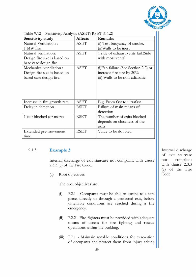
Table 9.12 – Sensitivity Analysis (ASET/RSET ≥ 1.2)
Sensitivity study Affects Remarks
Natural Ventilation : 1 MW fire
ASET (i) Test buoyancy of smoke. (ii)Walls to be inert
Natural ventilation: Design fire size is based on base case design fire.
ASET 1 side of exhaust vents fail.(Side with most vents)
Mechanical ventilation : Design fire size is based on based case design fire.
ASET (i)Fan failure (See Section 2.2) or increase fire size by 20% (ii) Walls to be non-adiabatic
Increase in fire growth rate ASET E.g. From fast to ultrafast
Delay in detection RSET Failure of main means of detection
1 exit blocked (or more) RSET The number of exits blocked depends on closeness of the exits
Extended pre-movement time
RSET Value to be doubled
9.1.3 Example 3 Internal discharge of exit staircase not compliant with clause 2.3.3 (c) of the Fire Code.
Internal discharge of exit staircase not compliant with clause 2.3.3 (c) of the Fire Code
(a) Root objectives The root objectives are :
(i) R2.1 - Occupants must be able to escape to a safe place, directly or through a protected exit, before untenable conditions are reached during a fire emergency.
(ii) R2.2 - Fire-fighters must be provided with adequate means of access for fire fighting and rescue operations within the building.
(iii) R7.1 - Maintain tenable conditions for evacuation of occupants and protect them from injury arising

60
from the effects of fire.
(iv) R7.2 - Provide smoke management in the building for firefighting operations.
(b) Sub objectives The sub objectives are :
(i) S2.9 - Provisions for adequate ventilation for means of escape.
(ii) S2.13 - Provisions for adequate time for occupant escape from building.
(iii) S2.14 - Provisions for safe movement of people within the means of escape.
(iv) S7.1 - Provisions for ventilation for life safety purposes such that in the event of a fire, evacuation routes are maintained :- (1) below thermal threshold for human tenability; and (2) at visibility levels adequate for occupant evacuation; and (3) below toxicity threshold for human tenability for the period of time required for escape.
(v) S7.2 - Provisions for ventilation to maintain safe conditions in the means of escape for evacuees for the period of time required for escape.

61
Table 9.13 – Design fires (sprinkler protected)
Usage Location
Size
Remarks
Atrium Centre Proposed by FSE Axis-Symmetric plume
Shop/unit 5MW (as prescribed by the fire code) or other appropriate fire size as proposed by FSE
Spill plume. FSE advised to seek consultation
Shopping Centre / Office / Mixed Use
Unit/s affecting egress path
5MW (as prescribed by the fire code) or other appropriate fire size as proposed by FSE
To determine impact of radiation on escaping occupants
All others Area with deviation
Proposed by FSE
Table 9.14 – Fire size proposed by FSE based on DETACT T2, FPETool or Firecalc
Usage
Growth rate
Remarks
All others Fast/Ultrafast 2nd ring sprinkler activation
Table 9.15 – Tenability Limits
Tenability Criteria
Radiation at egress path to external Radiation < 2.5 kW/m2
Smoke layer 2.5m above relevant FFL Visibility > 10m Temperature < 200oC
Smoke layer drops below 2.5m above relevant FFL
Temperature < 60oC
Table 9.16 – Acceptance Criteria
Scenario
Base case ≥ 2 Safety Factor (ASET/RSET) Radiation along evacuation route < 2.5 kW/m2
Sensitivity analysis ≥ 1.2 Safety Factor (ASET/RSET)
Perpetual tenability (Base cases) shall be required for health care occupancies and projects as deemed appropriate by SCDF (e.g. of national and cultural importance such as airport, Large-scale indoor gardens, National Art Galleries/Museums, etc.)

62
Table 9.17 – Determining RSET
Time for Method
Detection Refer to Section 4.1.
Notification time
Refer to Section 4.2.
Pre-movement
Refer to Section 4.3.
Movement Refer to Section 4.4.
Table 9.18 – Sensitivity Analysis (ASET/RSET ≥ 1.2)
Sensitivity study Affects Remarks
Natural Ventilation : 1 MW fire
ASET (i) Test buoyancy of smoke (ii)Walls to be non-adiabatic
Natural ventilation: Design fire size is based on base case design fire.
ASET 1 side of exhaust vents fail.(Side with most vents)
Mechanical ventilation : Design fire size is based on based case design fire.
ASET (i)Fan failure (See Section 2.2) or increase fire size by 20% (ii) Walls to be non-adiabatic
Increase in fire growth rate ASET E.g. From fast to ultrafast
Delay in detection RSET Failure of main means of detection
1 exit blocked (or more) RSET The number of exits blocked depends on closeness of the exits
Extended pre-movement time
RSET Value to be doubled

63
9.1.4 Example 4
Insufficient set back distance from notional boundary.
Insufficient set back distance
(a) Root objectives The root objectives are :
(i) R3.1 - Prevent the untimely collapse of buildings due to the effects of fire that would affect the safe egress of the building occupants.
(ii) R3.2 - Prevent spread of fire to adjacent properties due to the effects of a fire in the building.
(b) Sub objectives The sub objectives are :
(i) S3.7 - Provisions for prevention of spread of fire to adjacent buildings.
Table 9.19 – Design fires (sprinkler protected)
Usage Location
Size
Remarks
N.A. Relevant compartment
Proposed by FSE. Could be based on 84 kW/m2 or 168 kW/m2 depending on usage
May also be based on specific fuel load if it is known. Subject to SCDF’s approval
Table 9.20 – Acceptance Criteria
Scenario
Base case (i) Radiation on neighbouring building < 12.6 kW/m2 and
(ii) The radiant heat shall not be more than
12.6kW/m2 at twice the distance of the notional boundary of the building on fire,
64
Table 9.21 – Sensitivity Analysis
Sensitivity study Affects Remarks
Increase in fire growth rate (i) Increase fire size by 50%.
9.1.5 Example 5
Omission or Reduction of Fire rating of element of structure. Structural engineer is to carry out structural analysis with thermal input from FSE.
Omission or Reduction of Fire rating of element of structure
(a) Root objectives The root objectives are :
(i) R3.1 - Prevent the untimely collapse of buildings due to the effects of fire that would affect the safe egress of the building occupants.
(ii) R3.3 - The building shall remain structurally stable to allow adequate time for fire-fighters to conduct their fire-fighting and rescue operations.
(b) Sub objectives The sub objectives are :
(i) S3.1 - Provision of elements of structure with appropriate fire resistance with respect to :- (1) the fire severity; and (2) fire fighting and rescue operations; and (3) the occupant evacuation time; and (4) enclosure characteristics and configurations; and (5) the height of building; and (6) occupancy characteristics; and (7) different fire risk levels.
(ii) S3.2 - The construction and use of building materials should be of the type and method appropriate to the intended performance.
65
(iii) S3.9 - Provisions for reasonable measures to prevent premature structural collapse of the building due to fire.
Table 9.22 – Design fires (sprinkler protected)
Usage Location
Size
Remarks
Area of concern
Close to structural member in question
Proposed by FSE Based on post flashover fires. Refer to Clause 3.2(b) on computation of post flashover fires.
Table 9.23 – Acceptance Criteria
Scenario
Base case (i) Load-Capacity ratio ≤ 1. Structural engineer is to carry out structural analysis with thermal input from FSE. Annex I describes the steps to determine the load capacity ratio.
(ii) Smoke temperature less than limiting steel temperature.
Sensitivity Structure shall not fail due to failure of two or more key structural member(s) and increase fire size by 50%
9.1.6 Example 6
Ductless Jet Fans (Non-compliance(s) to FSR3:2008)
Ductless Jet Fans (Non-compliance(s) to FSR3:2008).
(a) Root objectives The root objectives are :
(i) R7.2 - Provide smoke management in the building for firefighting operations.
(b) Sub objectives N.A.

66
Table 9.24 – Design fires (sprinkler protected)
Usage Location
Size
Remarks
Vehicle/Car park
Least favourable location i.e. longest smoke path that is away from openings.
10 MW truck fire (as prescribed by the fire code) or higher (if deemed necessary by FSE)
Where trucks have access to the car park
4MW car fire/forklift fire (as prescribed by the fire code) or higher (if deemed necessary by FSE
Table 9.25 – Acceptance Criteria
Scenario
Base case Not more than 1,000 m2 of the car park can be smoke-logged for 20 minutes
Smoke temperature shall not exceed 250oC at a height of 1.7m
Visibility shall not be less than 5m at a height of 1.7m
All other areas outside the smoke-logged area shall be kept substantially free from smoke i.e. smoke temperature not more than 600C and visibility of at least 25m
There shall be at least one viable approach route for fire fighters
Sensitivity Analysis Failure of a group of jet fans nearest to the fire

67
REFERENCES
1. Singapore Civil Defence Force, Code of Practice for Fire Precautions in Buildings 2013
2. Ministry of Business, Innovation & Employment New Zealand, C/VM2
Verification Method: Framework for Fire Safety Design, April 2012
3. BENSILUM, M and PURSER D.A. (2002) GridFlow: an object-oriented building evacuation model combining pre-travel activity and movement behaviours for performance-based design. Fire Safety Science. Proceedings of the seventh International Symposium. EVANS, D.D. (ed.). International Association for Fire Safety Science. 2003. pp 941-952
4. BRYAN, J.L. An Examination and Analysis of the Human Behavior in the MGM
Grand Hotel Fire, revised report, National Fire Protection Association, Quincy MA, 1983
5. PD 7974-6:2004 - The application of fire safety engineering priciples to fire safety
design of buildings. Human factors. Life safety strategies. Occupant evacuation, behaviour and condition (Sub-system 6). British Standards Institution (BSI)
6. PROULX, G. KAUFMAN A. and PINEAU, J. Evacuation Time and Movement in Office Buildings, Internal Report No. 711, National Research Council of Canada, Ottawa ON, March 1996
7. PROULX, G. and FAHY, R.F. The time delay to start evacuation: review of five
case studies. proceedings of the fifth international symposium on fire safety science. HASEMI, Y. (ed.) International Association for Fire Safety Science, 1997, pp. 783-794
8. PROULX, G., LATOUR, J.C., MCLAURIN, J.W., PINEAU, J., HOFFMAN,
L.E. and LAROCHE, C. Housing Evacuation of Mixed Abilities Occupants in Highrise Buildings, Internal Report No. 706, National Research Council of Canada, Ottawa ON, August 1995
9. PROULX, G LATOUR J. and MACLAURIN, J. Housing Evacuation of Mixed
Abilities Occupants, Internal Report No. 661, National Research Council of Canada, Ottawa ON, July 1994
10. PROULX, G. and SIME, J. To prevent panic in an underground emergency, why
not tell people the truth?. In: COX, G., LANGFORD, B. (Eds), Fire Safety Science – Proceedings of the Third International Symposium. Elevier Applied Science, New York, pp. 843-852
11. R.L.Alpert, Fire Tech., 8, 181 (1972)

68
12. RICHARD D. PEACOCK, PAUL A. RENEKE, GLENN P. FORNEY, CFAST – Consolidated Model of Fire Growth and Smoke Transport (Version 6) User's Guide, NIST Special Publication 1041r1, National Institute of Standards and Technology, U.S. Department of Commerce, December 2012
13. RICHARD D. PEACOCK, PAUL A. RENEKE, Verification and Validation of
Selected Fire models for Nuclear Power Plant Applications, Volume 5: Consolidated Fire and Smoke Transport Model (CFAST), U.S. Nuclear Regulatory Commission, Office of Nuclear Regulatory Research (RES), Rockville, MD. 2007, and Electric Power Research Institute (EPRI), Palo alto, CA, NUREG-1824 and EPRI 1011999, May 2007
14. The Society of Fire Protection Engineers, The SFPE Handbook of Fire
Protection Engineering, 3rd Ed, National Fire Protection Association Inc., 2002, Chap7, Chap 8
15. WADE C.A. and Robbins A.P., Smoke Filling In Large Spaces Using Branzfire,
BRANZ Study Report No. 195, BRANZ Ltd, Judgefors, New Zealand, 2008
16. WADE C.A., A User Guide's Guide to BRANZFIRE 2004, Building Research Association of New Zealand, Judgeford, Porirua City, New Zealand, 2004
17. WADE C.A., BRANZFIRE Technical Reference Guide 2004, BRANZ Study
Report No. 92 (revised), Building Research Association of New Zealand, Judgeford, Porirua City, New Zealand, 2004
18. WALTER W.JONES, Richard D. Peacock, Paul A. Reneke, Glenn P. Forney,
Verification and Validation of CFAST, A model of Fire Growth and Smoke Spread, NISTIR 7080, National Institute of Standards and Technology, U.S. Department of Commerce, February 2004

Annex A – Methods of determining fire size (For sprinkler controlled fire)
Annex A-1

Annex B – Table of Fire Hazards
Usage Potential Fuel Load
Potential Ignition Sources
Hazards presented Potential mitigation measures
Areas of special/high hazard
Fuel or other or other flammable or combustible liquids storage rooms High hazard plant rooms High voltage switch rooms Heating appliances Kitchen appliances
Electrical, e.g. short-circuit of electrical appliances, wiring or switch boards From equipment, e.g. motors overheating Explosive or highly flammable/ignitable contents or activities
Fire hazards posed to occupants considered high Potential extreme event, such as explosion or uncontrolled fire to impact areas remote from fire
Clause 3.2.5 and Table 6.4A of the Fire Code
Back of house areas / service areas
Electrical and mechanical plant rooms Small ancillary usage (e.g. offices) Staff-only areas like changing rooms, etc
Electrical, e.g. short-circuit of electrical appliances, wiring or switch boards From equipment, e.g. motors overheating Smoking, e.g. ignition from cigarettes or matches
Flexibility in type of goods/commodities Illegal storage may impact means of escape and/or fire compartmentation
Fire compartmentation Automatic sprinkler protection Smoke purging / engineered smoke control
Shop (department stores, shopping centres, supermarkets, business and trades)
Commodities Display goods Storage
Electrical, e.g. short-circuit of electrical appliances or wiring Smoking, e.g. ignition from cigarettes or matches Overheating of electrical equipment Arson
Flexibility in type of goods/commodities Depending on type of shop and stacking arrangement, fire hazard can range from low to high (e.g. high rack storage). May connect multiple floors and/or have high populations (shopping centres)
Fire compartmentation Automatic sprinkler protection Engineered smoke control
Annex B-1

Usage Potential Fuel Load
Potential Ignition Sources
Hazards presented Potential mitigation measures
F&B (restaurants, food courts, coffee shops, hawker centres, fast food outlets)
Furniture and furnishings Rubbish bins Kitchen appliances Storage
Electrical, e.g. short-circuit of electrical appliances or wiring Overheating of electrical equipment, e.g. display lightings ‘Open flame’ cooking appliances in kitchens Smoking, e.g. ignition from cigarettes or matches Arson
Flexibility in type of furniture and layout Potential extreme event, such as explosion (gas cylinder/tanks/supply) to impact areas remote from fire May have high populations; e.g. foodcourts
Fire compartmentation Kitchen suppression systems Automatic sprinkler protection Engineered smoke control
Car parks Cars, motorcycles, vans Larger vehicles (load/unloading area)
Electrical, e.g. short-circuit of electrical appliances or wiring Overheating of electrical equipment Arson
May include high fuel load larger vehicles
Fire compartmentation Automatic sprinkler protection Smoke purging / Jet fan ductless system
Offices Furniture Electronic equipment Paper, books
Electrical, e.g. short-circuit of electrical appliances or wiring Overheating of electrical equipment
Flexibility in type of furniture and layout
Fire compartmentation Automatic sprinkler protection
Places of assembly (auditorium, theatres, performing arts)
Theatrical/stage scenery, hangings and other props (fly tower) Electrical equipment and lighting Fixed seating Performers’ instruments/props
Performances using pyrotechnics, flame effects or similar Electrical, e.g. short-circuit of electrical appliances or wiring Overheating of electrical equipment Smoking, e.g. ignition from cigarettes or matches Arson
Scenery can include props made from highly combustible materials; e.g. plastics Seats to be tested to BS 5852 as specified clause 2.8.3 (g) of the Code of Practice for Fire Precautions in Buildings. High populations and densities
Fire compartmentation Automatic sprinkler protection Smoke venting or engineered smoke control
Annex B2
Usage Potential Fuel Load
Potential Ignition Sources
Hazards presented Potential mitigation measures
Exhibition Exhibits may include temporary booths/setups and displays (electronics, vehicles, roadshows, sales, etc)
Overheating of electrical equipment Smoking, e.g. ignition from cigarettes or matches Arson
Flexibility in type of goods/commodities Flexibility in type of furniture and layout
Fire compartmentation Automatic sprinkler protection Engineered smoke control
Recreational, amusement, night entertainment
Furniture Theatrical/stage scenery, hangings and other props
Performances using pyrotechnics, flame effects or similar Overheating of electrical equipment Smoking, e.g. ignition from cigarettes or matches Arson
Scenery can include props made from highly combustible materials; e.g. plastics High populations and densities
Fire compartmentation Automatic sprinkler protection Engineered smoke control
Annex B3

Annex C – Enclosure Fire Models
(a) General There are generally two classes of computer models for analysing enclosure fire developments; Stochastic or Probabilistic models and Deterministic models.
(i) Stochastic model generally treat fire growth as a series of sequential events or states using established mathematical rules for the transition from one event to another. Probabilities are assigned to each transfer points based on analysis from experimental data, historical fire incident data or computer model results. The context of this model is not covered under this guide. Consultation with SCDF is required for the use of Stochastic model.
(ii) Deterministic models use interrelated mathematical expressions based on physics and chemistry to describe a compartment fire. The most common type of Deterministic model is the zone model, which solves the conservation equations in control volume(s). The other type of Deterministic model which gains popularity is the field model, which solves the fundamental equations of mass, momentum and energy in control volumes in subdivided grids.
(b) Zone Models
(i) Zone models are designed to predict the conditions resulting from a fire in an enclosure. These models solve the equations based on the zone assumptions within an enclosure. It provides a faster and a more accurate estimate of fire conditions than manual calculations methods. Most of the zone models can be run on personal computers. It is relatively simplicity, which permits inclusion of more phenomena in a given zone model without becoming overwhelmed by complexity. This also means that it may run far more rapidly and inexpensive.
(ii) It provides estimates of the fire conditions for each of the layers as a function of time. No zone model is the best for all applications. While most of the zone model are based on the similar fundamental principles, there is a significant variation features among the different zone models. The decision to use a model is dependent upon the understanding of the assumptions and its limitations for the particular model. Most importantly, the selected model must be validated with results comparing experiment data.
(iii) Application and limitations: (1) Simple geometry that can be simplified into a simple box, best applies to an
enclosure which dimensions (width and length) are similar.
(2) Large compartment are to be divided into multiple virtual compartments
Annex C1

(3) Radiation effects is not a primary consideration factor in the design
(4) Predicting sprinkler activation time and estimating ventilation rates
(5) Not well suited for comprehensive analyses involving the time-dependant interactions of multiple physical and chemical processes in developing fires
(6) Primarily one-dimensional, and divides the spaces of interest into a few zones
(7) Analyses of zone models assume two layers of uniform temperature and conditions; a hot upper zone and a cooler lower layer. Interaction of smoke with localised smoke logged conditions is not addressed, i.e. compartment volumes are strongly stratified
(8) Different zone models may yield quite a different results
(9) Not accurate in modelling long corridors, very large compartments or compartment involve radiation feedback of energy
(10) Smoke movement cannot be predicted
(11) Cannot generate pictorial results that describes a more realistic fire conditions
(iv) Zone models are intended to be used to review the smoke transport with a wide variety of fire scenarios. Some of the limits to the inputs in the softwares are reproduced from the various references and listed below. The list of softwares shown is not exhaustive with a few commonly used software for zone model presented. It is important to understand the physics and assumptions on which the software is based in order to evaluate and interpret the results.
Annex C2

Table C-1 – Limitations of CFAST and BRANZFIRE
S/N Description CFAST BRANZFIRE
1 Maximum simulation time 86,400s [12]
2 Maximum number of compartments 30 [12] 10 [16]
3 Maximum number of fires which can be included in a single test case (including the main fire)
31 [12]
4 Maximum number of fire definitions which can be included in a single fire database file
30 [12]
5 Maximum number of data points for a single main or secondary object fire
21 [12]
6 Maximum number of material property definitions which can be included in a single thermal database
125 [12]
7 Maximum number of slabs in a single surface material in the thermal database file
3 [12]
8 Total number of ducts in all mechanical ventilation systems which can be included in a single test case
60 [12]
9 Maximum total number of connections between compartments and mechanical ventilation systems which can be included in a single test case
62 [12]
10 Maximum number of independent mechanical ventilation systems which can be included in a single test case
15 [12]
11 Maximum number of targets which can be included in a single test case
90 [12]
12 Maximum number of data points in a history or spreadsheet
900 [12]
13 Maximum single compartment size 1,200m2 [15]
14 Maximum total virtual compartments size 5,000m2 [15]
15 Maximum compartment height Ceiling Jet 0.58m to 22m [18]
12m [15]
16 Maximum compartment volume 60,000m3 [15]
17 Maximum length of compartment 25m [4]
18 Maximum fire size Ceiling Jet only 0.62MW to 33MW
Annex C3

S/N Description CFAST BRANZFIRE
19 Minimum fire size within room of fire origin (This limit is not to be used as a limit to a specific design fire)
0.1 kW/m3 [3]
20 Maximum fire size within room of fire origin (This limit is not to be used as a limit to a specific design fire)
1000 kW/m3 [13]
21 Maximum ratio of area of vents connecting one compartment to another to the volume of the compartment
< 2m-1 [13]
22 Corridor Scenario – aspect ratios as follows: * (L/W)max * (L/H)max * (W/H)min
L/W > 5 [13] L/H > 6 [13] W/H < 0.2 [13]
23 Special consideration for Corridor with use of corridor flow and non-corridor flow algorithm for comparison - aspect ratios as follows: * (L/W)max * (L/H)max * (W/H)min
3 <L/W< 5 [13] 3 <L/H< 6 [123 0.2<W/H<0.4 [13]
24 Single Zone compartment scenario – aspect ratios as follows: * (L/W)max * (L/H)max * (W/H)min
L/W < 3 [13] L/H < 3 [13] W/H > 0.4 [13]
*List not exhaustive
(v) List of Approved Zone Models:
CFAST
BRANZFIRE
To seek consensus from SCDF for the use of other zone models
(c) Field Models
(i) The field model solves fundamental Navier-Stokes equations using numerical method, commonly known as computational fluid dynamics (CFD). It allows study of extremely complicated problems even with irregular and complex geometry. The primary advantage of a field model is that it can provide detailed information on the fluid motions in three-dimensions as compared with zone model (except one-dimensionally). In general, a more powerful computer than desktop personal computer will be required to run CFD.
Annex C4

(ii) It computes the mass, momentum and energy conditions of the fire conditions for each of the cell within the grid or mesh as a function of time. Like the zone model, no field model is the best for all applications. Most of the field models are based on the similar fundamental principles but there is a significant variation features among the different field models. Understanding of the assumptions and its limitations for the particular model is required in order to select the appropriate field model to be used. Again, most importantly, the selected model must be validated with results comparing experiment data.
(iii) Application and limitations:
(1) No constraint in using field model for any geometry
(2) Detail analyses required
(3) Experience users with knowledge of fluid dynamics codes
(4) Powerful computer required to run CFD
(5) Large data storage for results
(6) Long computing time
(7) Results are grid dependant; i.e. Solution is less ideal for coarser and very fine
grids or mesh
(iv) List of Approved Field Models:
Fire Dynamic Simulator (FDS)
FLUENT
Phoenics
To seek consensus from SCDF for the use of other field models
Annex C5
Annex D – Notification time
(a) The following describes typical design notification times, depending on the types of alarm systems present and the evacuation strategies being adopted:
(i) From C/VM2 document Cl 3.2.2
tn = 30 s for premises adopting standard evacuation strategies;
For non-standard evacuation strategies (i.e 2-stage, management investigating, etc), tn will have to take into account any extended timeframe.
(ii) From PD7974 Part 6:2004 Annex A
If the building is fitted with automatic fire detection systems with immediate fire alarm, then tn = 0 s;
If the building is fitted with automatic fire detection system involving a pre-alarm to building management, and thereafter either (1) a manually activated warning sounded throughout affected area, or (2) if pre-alarm is not cancelled after a fixed delay, then a general alarm will be sounded. In such cases, the notification time can be taken as:
tn = 2 min to 5 min + time taken for voice alarm to be spoken twice.
If the building is fitted with only local automatic alarm near the fire location, or is not fitted with any automatic alarm at all, occupants will be notified of fire only via manually activated general warning system. In such cases, notification time may be long: tn = long and unpredictable.
(iii) From SS CP10 : 2005
Cl 1.4.3.3 Fire extinguishing alarm initiating devices.
Flow switches, pressure switches and the like associated with fixed fire extinguishing systems that are used to initiate an alarm, shall be individually connected under separate alarm zones on the fire alarm panel. Flow switches used shall incorporate time-delay devices to avoid false alarm due to water surges.
Initiation of the alarm signal shall occur within 90s of water flow at the alarm-initiating device when flow occurs that is equal to or greater than that from a single sprinkler of the smallest orifice size installed in the system.
Cl 2.5.11 Alarm verification feature (AVF).
Annex D1
To reduce the effects of transient environmental conditions, which may cause various types of detectors to be activated, an automatic fire alarm system may be provided with an alarm verification feature, subject to the approval of the relevant authority.
Such an alarm verification feature, if provided, shall operate in the following manner. Upon activation of a detector in any zone, the fire alarm system shall go into an alarm retard state for a period not exceeding 20s at the control unit. After the expiry of this period, the fire alarm system shall go into an alarm confirmation state for a period not less than 120s and not exceeding 300s. Only when the same detector or another detector within the same zone or panel is activated during this alarm confirmation period, shall the fire alarm system go into full operation.
Cl 2.7.2 Detectors. The delay between activation of a heat detector and activation of the general alarm shall not exceed 10s.
Annex D2

Annex E – Warning systems
(a) Alerting people with warning systems (Source: C/VM2) Where only manual systems are installed, occupants are assumed to be aware of the fire when the ceiling jet has traversed the entire length of the space from a fire at the opposite end of the space. No additional pre-movement time need be included. The time required for the ceiling jet to completely traverse the ceiling can either be determined using CFD modelling or by the following relationship if zone modelling is used.
(i) For storage height ≤ 5.0m (ultrafast fire growth):
td = 10 + 2.4L when L ≤ 1.4w, and td = 10 + w + 1.7L when 1.4w < L ≤ 4w, and For storage height > 5.0m (ultrafast fire growth): td = 25 + 1.7L when L ≤ 1.4w, and td = 25 + w + L when 1.4w < L ≤ 4w, where: w = width of space in meters (shortest dimension) L = length of space in meters (longest dimension)
Annex E1

Annex F – Pre-movement time
(a) In essence, pre-movement time depends primarily upon the design behavioural scenario, the fire safety management level and building complexity. The New Zealand document, i.e. C/VM2 attempts to prescribe the pre-movement times for various building usage groups, occupant alertness, familiarity and proximity to fire origin. However, these pre-movement times obtained from C/VM2 do not take into account the behavioural modifiers (e.g. detection and alarm quality, level of fire safety management and building complexity) in determining pre-movement times.
(b) The level of fire safety management can be significant in reducing pre-movement times. Pre-movement times and their corresponding distributions have been found to be very short when fire safety management is of a high standard and when staff is well-trained [Purser, Bensilum & Purser 2002].
Annex F1
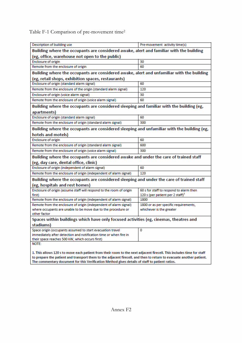
Table F-1 Comparison of pre-movement time2
Annex F2

Annex G – Circular on Certification by QP for A/A Plans involving PB Fire Safety Designs.
Annex G1

Annex G2

Annex H –First Schedule of the Fire Safety (Registered Inspector) Regulations
FIRST SCHEDULE SCOPE OF FIRE SAFETY WORKS TO BE INSPECTED BY APPROPRIATE
REGISTERED INSPECTORS
A registered inspector who —
(a) is an architect registered under the Architects Act [Cap. 12] or a professional engineer in the civil or structural engineering discipline registered under the Professional Engineers Act [Cap. 253] shall inspect and, unless otherwise provided, test the fire safety works listed in Part I;
(b) is a professional engineer in the mechanical or electrical engineering discipline registered under the Professional Engineers Act [Cap. 253] shall inspect and test the fire safety works listed in Part II; and
(c) possesses a degree in Fire Safety Engineering which is acceptable to the Commissioner shall inspect and, unless otherwise provided, test the fire safety works listed in both Parts I and II.
PART I (1) Fire Protection Systems:
(a) Fire extinguishers (b) Dry risers (testing not required). (c) Manual fire alarm callpoints, sounding devices and indicating panel (testing not required). (d) Exit and directional signs. (e) Emergency lighting (self-contained light fittings only). (f) Hosereels (direct Public Utilities Board supply).
(2) Structural Fire Precautions:
(a) Compartment walls and floors. (b) Elements of structure. (c) External walls. (d) Separating walls. (e) Protected shafts. (f) Protection of openings (excluding fire dampers). (g) Exit staircase. (h) Concealed spaces. (i) Fire stopping. (j) Restriction of flame spread. (k) Roofs.
(3) Means of Escape.
Annex H1

(4) Site planning and external fire fighting provisions:
(a) Fire fighting vehicles and equipment access (access opening and hardstanding/access way). (b) Rising mains access. (c) Hydrants and private hydrants (testing not required). (d) Fire Command Centre.
(5) Any other endorsements made on the approved building plans.
PART II
(1) Fire Protection Systems:
(a) Sprinkler systems. (b) Automatic fire alarm systems, including testing of manual alarm systems. (c) Lift systems. (d) Hosereels (pump supply). (e) Wet risers. (f) Dry risers and internal hydrants (testing only).
(2) Mechanical ventilation/air-conditioning systems, including dampers and fire resisting construction of ductworks. (3) Smoke control systems (both mechanical and venting systems). (4) Pressurisation systems. (5) Emergency lighting. (6) Voice communication systems and Fire Command Centre facilities. (7) Standby generator systems. (8) Integrated fire fighting and protection systems testing under both fire alarm activation and power failure condition. (9) Any other endorsements made on mechanical ventilation and fire protection plans.
Annex H2
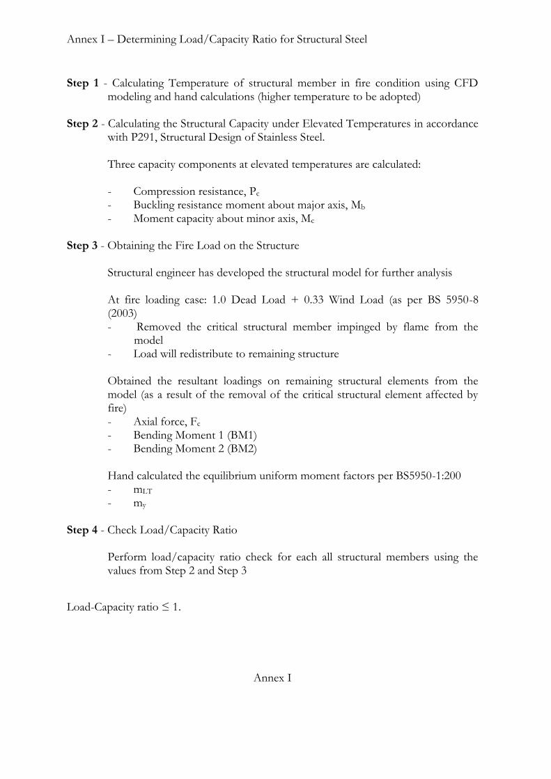
Annex I – Determining Load/Capacity Ratio for Structural Steel
Step 1 - Calculating Temperature of structural member in fire condition using CFD modeling and hand calculations (higher temperature to be adopted)
Step 2 - Calculating the Structural Capacity under Elevated Temperatures in accordance
with P291, Structural Design of Stainless Steel.
Three capacity components at elevated temperatures are calculated:
- Compression resistance, Pc - Buckling resistance moment about major axis, Mb - Moment capacity about minor axis, Mc
Step 3 - Obtaining the Fire Load on the Structure
Structural engineer has developed the structural model for further analysis At fire loading case: 1.0 Dead Load + 0.33 Wind Load (as per BS 5950-8 (2003) - Removed the critical structural member impinged by flame from the
model - Load will redistribute to remaining structure
Obtained the resultant loadings on remaining structural elements from the model (as a result of the removal of the critical structural element affected by fire) - Axial force, Fc - Bending Moment 1 (BM1) - Bending Moment 2 (BM2)
Hand calculated the equilibrium uniform moment factors per BS5950-1:200 - mLT - my
Step 4 - Check Load/Capacity Ratio
Perform load/capacity ratio check for each all structural members using the values from Step 2 and Step 3
Load-Capacity ratio ≤ 1.
Annex I


![CUSTOMS’ TRANSFORMATION OURNEY - etouches · Customs [incl National Authority (CWC)] Health Sciences Authority Singapore Police Force Singapore Civil Defence Force Ministry of Health](https://static.fdocuments.net/doc/165x107/5e58315df6238d1d3f28e160/customsa-transformation-ourney-etouches-customs-incl-national-authority-cwc.jpg)