
(since 1962) - FIT
24
May 27, 2007 Page 1 of 2 !" $%&’() * +,-)./01 2)’3%0&’,4 * 5%06-) 778 * +,-)./019 :; 8<=>7?<>@A engineering310.stanford.edu global team-based design innovation with corporate partners tools, methods, and strategies for high performance development teams, 2007-2008 A Radical Course (since 1962) You are invited to participate in Engineering 310abc: Global Team-Based Design Innovation with Corporate Partners. In this award-winning, thirty-week, graduate-level-depth sequence, you’ll work with Stanford faculty, students, staff and their extraordinary network of innovation. Offered by the Mechanical Engineering Design Group, this course is open to Stanford students from all disciplines. Its global network of faculty and students come from some of the most distinguished design programs around the world. In this course, Stanford Masters and PhD degree candidates (typically possessing one to six years of practical engineering experience) are introduced to the tools, methods and thinking strategies needed to form and creatively manage distributed design engineering teams. The course is well known for taking ideas from concept to fully functional proof-of-concept prototypes suitable for engineering and customer evaluation. Our graduates are also highly skilled at navigating the entire innovation process, from conceptual brainstorming to comprehensive documentation and manufacturing. Driven by student demand and corporate practice, we have engaged a network of global academic partners to bring exceptional diversity to our various teams. Diversity has been demonstrated to correlate highly with design team innovation, and it is one of the core variables that Stanford’s Center for Design Research finds valuable. As a corporate partner, you will be working with paired teams of three to four students on Stanford’s campus and three to four students at one of Stanford’s select foreign university programs. For the 2007–2008 academic year we have engaged the following institutions: Helsinki University of Technology, Finland; University of St. Gallen, Switzerland; Hasso Plattner Institute at the University of Potsdam, Germany; Royal Institute of Technology, Stockholm, Sweden; Pontificia Universidad Javeriana, Cali, Colombia; and Universidad Nacional Autónoma de México, Mexico City, Mexico. Multi-disciplinary teams examine industry-proposed design challenges from many perspectives, including cultural factors, business design, market potential, and technical feasibility, all in order to determine specific product and performance requirements. These teams reduce functional solutions to practice within nine months using 2.2 to 2.6 person-years, assuming 35% effort levels for 6 global team members. Faculty consulting contributions are a significant side benefit. Student Team at Work A Teaching Team Professors Mark Cutkosky (ME) and Larry Leifer (BioEngr) co-instruct the course. They are aided by Consulting Professors Victor Scheinman (ME, ASME Leonardo da Vinci award winner) Bob Plummer (CS) as chief technical officer and software architect, respectively. Five post-Masters graduate students serve as teaching assistants. Each team is assigned an engineering-culture coach — volunteers who typically have taken 310 and have between five and thirty years of professional experience with deep networks in the Bay Area and the global technical community. Technologically, the course is supported by Consulting Professors George Toye (ME) and Bruce Boyd (IT), and administratively by Ms. Michelle Lucas. In short, you will be working with an extraordinary team. Outcomes You Can Expect Projects for 310 are suggested by industry partners and refined through consultation with the teaching team. Successful projects tend to be new-product-related innovation challenges driven by real-world issues that are of vital interest to the company in question. Most projects include human-machine interaction, service engineering, and manufacturing issues — all subjects that demand attention to ergonomics, software design, and socio-technical factors. At the same time, they pay close heed to the mechatronic systems fundamentals that are the Stanford Design Group’s core competency.
Transcript of (since 1962) - FIT

May 27, 2007 Page 1 of 2
!"#$%&'()#*#+,-)./01#2)'3%0&',4#*#5%06-)#778#*#+,-)./019#:;###8<=>7?<>@A#
engineering310.stanford.edu global team-based design innovation with corporate partners tools, methods, and strategies for high performance development teams, 2007-2008
A Radical Course (since 1962) You are invited to participate in Engineering 310abc: Global Team-Based Design Innovation with Corporate Partners. In this award-winning, thirty-week, graduate-level-depth sequence, you’ll work with Stanford faculty, students, staff and their extraordinary network of innovation. Offered by the Mechanical Engineering Design Group, this course is open to Stanford students from all disciplines. Its global network of faculty and students come from some of the most distinguished design programs around the world.
In this course, Stanford Masters and PhD degree candidates (typically possessing one to six years of practical engineering experience) are introduced to the tools, methods and thinking strategies needed to form and creatively manage distributed design engineering teams. The course is well known for taking ideas from concept to fully functional proof-of-concept prototypes suitable for engineering and customer evaluation. Our graduates are also highly skilled at navigating the entire innovation process, from conceptual brainstorming to comprehensive documentation and manufacturing.
Driven by student demand and corporate practice, we have engaged a network of global academic partners to bring exceptional diversity to our various teams. Diversity has been demonstrated to correlate highly with design team innovation, and it is one of the core variables that Stanford’s Center for Design Research finds valuable. As a corporate partner, you will be working with paired teams of three to four students on Stanford’s campus and three to four students at one of Stanford’s select foreign university programs. For the 2007–2008 academic year we have engaged the following institutions: Helsinki University of Technology, Finland; University of St. Gallen, Switzerland; Hasso Plattner Institute at the University of Potsdam, Germany; Royal Institute of Technology, Stockholm, Sweden; Pontificia Universidad Javeriana, Cali, Colombia; and Universidad Nacional Autónoma de México, Mexico City, Mexico.
Multi-disciplinary teams examine industry-proposed design challenges from many perspectives, including cultural factors, business design, market potential, and technical feasibility, all in order to determine specific product and performance requirements. These teams reduce functional solutions to practice within nine months using 2.2 to 2.6 person-years, assuming 35% effort levels for 6 global team members. Faculty consulting contributions are a significant side benefit.
Student Team at Work
A Teaching Team Professors Mark Cutkosky (ME) and Larry Leifer (BioEngr) co-instruct the course. They are aided by Consulting Professors Victor Scheinman (ME, ASME Leonardo da Vinci award winner) Bob Plummer (CS) as chief technical officer and software architect, respectively. Five post-Masters graduate students serve as teaching assistants. Each team is assigned an engineering-culture coach — volunteers who typically have taken 310 and have between five and thirty years of professional experience with deep networks in the Bay Area and the global technical community. Technologically, the course is supported by Consulting Professors George Toye (ME) and Bruce Boyd (IT), and administratively by Ms. Michelle Lucas. In short, you will be working with an extraordinary team.
Outcomes You Can Expect Projects for 310 are suggested by industry partners and refined through consultation with the teaching team. Successful projects tend to be new-product-related innovation challenges driven by real-world issues that are of vital interest to the company in question. Most projects include human-machine interaction, service engineering, and manufacturing issues — all subjects that demand attention to ergonomics, software design, and socio-technical factors. At the same time, they pay close heed to the mechatronic systems fundamentals that are the Stanford Design Group’s core competency.

May 27, 2007 Page 2 of 2
!"#$%&'()#*#+,-)./01#2)'3%0&',4#*#5%06-)#778#*#+,-)./019#:;###8<=>7?<>@A#
Students drive the project forward while learning through a sequence of experiments based on increasingly refined prototypes. Actions and thought are continuously documented and summarized at the end of each quarter with a comprehensive document. The first report (issued in December) defines client-customer needs and design requirements. The second (March) report details performance requirements and test-validation protocols. The third (June) report documents concept realization, outcome characterization, and user testing. To quote Donald Knuth (CS), the goal is to “capture the intelligence of the design, not just the outcome of the design.”
Project results are always copyrighted, often patented, and commonly implemented by the corporate partner. While results cannot be guaranteed, the course has an outstanding IP creation track record. In addition to the quarterly reports, corporate partners receive all related hardware and software constructed during the course. Intellectual property rights are initially co-owned by Stanford and the relevant partner, based on the assumption that non-disclosure content was essential to the invention. The Stanford Office of Technology Licensing is our partner in negotiating exclusive licenses.
Winning Project Features In order to be successful, a winning project will usually do the following:
1. Challenge students' creative and intellectual abilities. 2. Be conceptually and technically challenging while
retaining modest cost and physical size. 3. Be of deep concern to the company, but not on a critical
production path. 4. Give the relevant student learning team considerable
freedom of action and decision-making authority. 5. Benefit from an open-door policy between student team,
company liaison, and company knowledge and insight.
All of these factors are important individually, but when assembled together, they provide a remarkable path for success and fulfilling, beneficial achievement.
Liaison Guidelines The academic and corporate success of a project in Engineering 310 depends greatly on the existence of an effective company liaison. It is vitally important that the liaison be willing and able to meet with the design team regularly, serve as the point-of-contact for corporate expertise and has project background information to be able to assist in developing design requirements and associated test and validation protocols.
Liaisons should plan on at least one face-to-face meeting in November and at least two other meetings on campus or at company sites over the course of the project. We recommend weekly communication via email, telephone, fax and/or videoconference. Internet video conferencing is available in Terman room 583 (the 310-loft) and Terman room 501 (tele-studio).
Prototype of “Enhanced Passenger Communication” System
Company Financial Commitment The Stanford Affiliate project fee for the 2007-2008 term remains set at $75,000 for one 30-week project team at Stanford, plus the fees required by the Academic Partners (these range from $25,000 to $50,000 depending on local circumstances). Fees cover costs, and include university infrastructure charges, teaching team time, laboratory services, travel, telecommunication services, and prototype fabrication. The exact terms and routing of payments are negotiated on a flexible case-by-case basis.
Project Proposal Timing In order to ensure a project slot in the course, it’s requested that you confirm participation in Engineering 310 and indicate an academic partner institutional preference for the academic year 2007-2008 as soon as possible. Teams are reserved on a first-come, first-served basis after we have received a letter of intent. We will then invoice you for a deposit of $25,000, due within 45 days. The receipt of the funds confirms a project in Engineering 310 and the availability of the preferred partner institution. After confirmation of the project, please submit a 1-4 page project abstract as soon as possible and no later than the end of September.
If you would like to begin the project development process, please contact the 310 Executive Director, Philipp Skogstad at [email protected] or (650) 799-0298.
Key Dates for 2007-2008
September 31, 2007: Project Proposals Needed October 23, 2007: Projects Presented to Design Teams December 6, 2007: 310 Autumn Design Reviews (Product Definitions) March 13, 2008: 310 Winter Design Review (Proof of Concept) June 4 & 5, 2008: 310 Spring Design Review and EXPE'08
ME310 2006-07
STANFORD UNIVERSITY MECHANICAL ENGINEERING
Stanford Team Daniel Clark
Gautam Dandavate Quan Gan
June Zhang Joel Dillon (Coach)
TUM Team Andreas Lamprecht Dominic Schmolz Torsten Stoewer
Nico Stuber Ferdinand Wiesbeck (Coach)
CORPORATE SPONSORS
Volkswagen of America Electronics Research Lab
Liaisons: Daniel Rosario Brian Ng
Audi AG Liaison: Dr. Uwe Koser
Background With the average person today spending a significant amount of time in their vehicle, Audi has posed the question as to whether this time can be used to maintain or improve the vehicle occupant’s fitness. A global design team, consisting of students at Stanford and TUM, was asked to design fitness solutions within the car environment. Vision The design team has come up with two design concepts to achieve this goal: Roboseat The Roboseat is a motorized seating system targeted at improving the physical well-being of the vehicle occupants. It is based on the physical therapy technique of continuous passive motion (CPM). The seat periodically moves and changes the seat occupant’s posture to prevent back pain that arises from static seating.
Driving Dynamics Center The Driving Dynamics Center is targeted at improving driving fitness. The vehicle’s dynamics are measured in real-time and reported to the driver through intuitive visual animations on the dashboard display in order to provide feedback on his/her driving performance.
The dashboard display shows info. on the vehicle’s dynamics, such as the amount of understeer or oversteer. This provides the driver a better understanding of his/her driving performance
The car seat actuators are made to move through CPM cycles in order to avoid back pain associated with stationary seating
Design Requirements The Audi Trainer system has the following requirements: Demonstratively improves the user’s fitness, as determined from expert evaluation and user-testing Is user-friendly and comfortable to use Does not inhibit or distract the user from the primary task of driving Accommodates a wide spectrum of users Conforms to the fit and finish of an Audi vehicle Appeals to both North American and European markets
Design Strategy The team approached the design problem by defining “fitness” into three major categories: physical fitness, driving fitness and mental fitness. The team conducted need-finding, brainstorming, benchmarking and prototyping activities for all three areas of fitness. From these activities, the team chose to pursue design solutions in the first two categories as they showed the strongest potential for fitness improvement in a vehicle.
The final prototype consists of the Roboseat and Driving Dynamics Center integrated into a 2005 Audi A6. The car seat was modified to add additional degrees of freedom, such as seat yaw and refined lumbar support. The seat actuators are controlled by on-board microcontrollers. The Driving Dynamics Center reads vehicle sensor data from the CANBUS, and then processes and outputs it to the dashboard display via an on-board computer.
With the Audi Trainer prototype, the team strongly believes it has designed an innovative, integrated fitness development system for the vehicle environment that provides real benefit to the user.
Seat yaw DOF added to car seat to provide spine rotation
bearing plate
linear actuator
Hardware, including computer and microcontrollers installed in trunk
computer
micro- controller
Audi A6 - the test bed for the Audi Trainer prototype
A preliminary prototype aimed at instructing the driver when to shift gears through visual and haptic indicators
A preliminary prototype of a seated pedaling machine installed in the car to provide a cardio workout
LCD screen
vibrating motors

The CEER Room investigates how large multi-purpose learning spaces can be augmented to promote and facilitate collaboration among groups of various size and global reach, with technology and environmental requirements that adapt over the duration of the activities within. The design team investigated how methods of communication and interacting with technology can be made more intuitive and present for both local and remote users.
Client:Civil and EnvironmentalEngineering
Client Liaisons:• Renate Fruchter• John Haymaker
Stanford University:• David Sirkin• Doug Tarlow• Patrick Summers
University of Queensland:• Andrew Dekker• Bonnii Weeks
Coached By:• Ann Morrison• Ian Maccoll• John Murray• Margot Brereton
Teaching Team:• Mark Cutkosky• Larry Leifer• Vic Scheinman• Mike Van der Loos• Alissa Murphy• David Yao• Micah Lande
Team Contact:• [email protected]
Civil & Environmental Engineering Reconfigurable Room
Making Remote Collaborators More Present
Rosie• provides movable, physical presence of remote user• remotely controlled screen shows gaze and attention• 3 articulated monitors suit class and team workspace• multi-platform OS for document and screen sharing
Multi-touch• enables multi-user collaboration on a
single display• gestural communication for usability
and context• scalable from notebook up to large
wall size• unique node-link diagram design
authoring mode
Design Requirements
☑ Enhance the presence of globally dispersed students in classroom and team settings
☑ Permit remote and local students to author design documents as a group
☑ “Some assembly required” design lets clients build devices on their own
☑ Enhance existing technologies available in current interactive technology rooms
☑ Efficient (near-immediate) setup and adaption times
☑ Support activities involving individuals or groups consisting of 1, 3, 10, 30 or 80 occupants
Design Process
User Scenario
Design Challenge
Through needfinding, benchmarking, prototyping and user observations, the CEER team identified a problem with current remote collaboration:
Video conferencing to several different locations results in feeds that contend for size and position on a single local display. This reduces the representation and impact of remote participants, diminishes their expressions and gestures, and makes it difficult for them to direct the attention of others.
Traditional workspaces center around a single user in a static location. The CEER team’s solution facilitates multi-user input and the ability to dynamically reconfigure to the changing needs of the rooms’ occupants.

DaimlerChrysler Corporation Auburn Hills, MI 48326-2766
Liaisons:
Matthias Bauer John Mrozowski
Coaches:
Shad Laws – Local Sanja Skejo – Global
_____________________________________
Stanford Team
_____________________________________
KTH Team
Background
Emerging technologies and devices have enabled the migration of large scale information display into the vehicle, thereby significantly increasing human-machine interface design challenges and opportunities. There exists a need for new devices to blend harmoniously into the limited interior of the automobile environment making best use of the available space, while at the same time remaining logical in their operation and appealing in their visual presentation.
Continuous multi-window touch screen display for driver and
passenger
The Pangea Interface is a new approach to meeting the challenges and opportunities of large-scale, customizable information display in the car. Unlike other solutions today, the Pangea Interface replaces all the familiar physical controls, such as knobs and buttons, with software and large touch sensitive displays that allow for a reconfigurable visual and tactile experience. This allows the Pangea Interface to provide virtually unlimited functionality while reducing driver distraction and enhancing intuitiveness by letting users choose the best configuration of graphical functions for a given situation.
Stanford University KTH - Royal Institute of Technology
ME 310 : 2006-2007

Interface Functionality
The left “tab” allows the selected function (bottom) to move into the primary position.
The “change” and “add” buttons bring up icons allowing the user to quickly decide which new function will join the current layout (change) or which new function will be added, forming a revised layout (add).
The passenger has an additional display for advanced tasks.
Design Development In an effort to make the interaction with information in the car superior to interface schemes today, the team first studied the best aspects of current interfaces and technologies, while keeping in mind the target users (drivers under 30 years of age). Knowing that in the future, diverse forms of information will need to be displayed in specific locations within the car, the team considered using multiple displays, moving displays, portable/supplementary displays, and augmented reality windshield displays. The most important attributes of each of these approaches were identified to arrive at a large, high resolution and continuous display that can be customized to change dynamically according to the desires of the driver and passenger.
Features
Displays • A 7” driver display located in the current
instrument panel gives the driver essential vehicle information.
• A 17” vertically mounted widescreen display in the center console area gives both the driver and passenger the ability to control the cabin environment and access driver appropriate media.
• A 19” widescreen display on the dashboard in front of the front passenger gives the passenger additional functionality for advanced media and productivity tasks that are not appropriate for the driver when the car is in motion.
Interaction Methods
• The center console and passenger screens are touch sensitive, permitting direct manipulation.
• A touchpad for the passenger, mounted on the door arm rest, allows for user comfort during continuous use.
• Bluetooth phone support allows for the use of a cell phone’s QWERTY keyboard for text input.
Software
• Function “tabs” allow for quick and easy reprioritization of function locations.
• “Add” and “subtract” buttons allow for the easy addition or removal of functions to the display.
• “Change” buttons allow for the switching of functions without reorganizing the display layout.
• Graphical layout customization is a reality.

An Innovative Compressed Air and
Vacuum Delivery System
ME-310 2006-2007
Team DCI
Stanford University Team:
Tanmay Mishra
David Quintero
Brandon Smith
Rajveer Tut
Fukuoka Institute of
Technology Team:
Koji Kitashima
Atsushi Kondou
Satoshi Nishimoto
Corporate Liaisons:
Glenn Klecker
Tim Bukoski
Team Coaches:
Dr. David Grossman
Dr. Masaaki Imamura
Dr. Yoshiyuki Kawamura
Background
Compressed air and vacuum are the backbone of dental offices around the
world. They are used to run dental tools, dry working surfaces and keep the oral
cavity clean. However, providing these functions typically requires a large initial
investment in two separate, noisy and large pieces of machinery with associated
infrastructure.
High equipment costs are a hindrance for small dental startups as well as
developing nations. Therefore, they require lower-cost alternatives to meet the
same, and sometimes even more demanding dental and medical needs.
Additionally, mobile dental units provide the only means of treatment in
remote, hard to access areas with
Vision & Design Challenge
The design team’s vision is to
extend the reach of quality
dental care to remote
locations as well as making it
financially viable for dental
startups. Our goal is to
develop a portable, quiet and
economical integrated
solution for compressed air
and vacuum delivery. Ideally
this unit could be located
conveniently within a dentist’s
operatory, while also being
capable of functioning as a
portable unit for mobile
dentistry.
Figure 1: Fully assembled
frame with all components
poor medical infrastructure.

Key Features of the Design
• Elimination of compressed air storage tank through implementation of an on-demand system using
closed-loop feedback control
• Use of an innovative air compression technology: the scroll compressor
• Use of powerful yet light weight aircraft industry grade reciprocating piston vacuum pump to provide
adequate suction
• Vibration isolation and dampening by use of silicone gel spring mounts
• Noise reduction using vinyl backed polyurethane foam lining in the enclosure
• Reducing failure severity by providing user option of bypassing the control system and using a simple
on/off system.
• Enhanced portability by compact and robust packaging of all the auxiliary components
Design Requirements
Key requirements for a portable system given by the project sponsors, DCI International include:
• Ability to provide compressed air with a minimum requirement of 3SCFM @ 80PSIG
• Ability to provide vacuum with a required value of 7SCFM at 6-8 Inches of Mercury
• The air is required to be clean (Pass through a 5Micron particulate filter) and dry (Maximum Relative
Humidity of 36%)
• Portable, with ideal weight less than 50 lbs.
• Low noise level, ideally less than 60Decibels
• Maximum dimensions: 3ft. X 3ft. X 1.5ft. enabling one human to be able to carry it.
These requirements formed the starting point for extensive research on compressor and vacuum types, control
systems and other technologies relevant to the design. We were also concerned with human factors and
interviewed dentists involved in outreach dentistry as well as dental students at the University of Pacific.
Another important consideration during design was to maximize the marketability of the design and so we
strove to innovate in every possible aspect of the project against the norms of the very conservative dental
community. Besides using innovative technologies for compression and vacuum, we eliminated the air storage
tank in order to reduce the overall size and weight of the system. In this direction, we implemented an on-
demand compressed air supply system based on closed loop feedback control.
Figure 2: Schematic diagram
of system operation
duo by futureformfutureform is:Kevin Aberdeen Pascal KalbermattenJohn Aliquo Claudio LimacherRebecca Armenta Isabel SauterLarry Cheng, Coach Ernst Ensslin, CoachAndreas Tittel, Liaison, DB Systems
Work. Together.
Where do you see yourself on this day twenty years from now? In the office? Working from home while preparing lunch? On the beach of your Tahitian dream house?
Wherever you want to be, and wherever you need to be, duo will allow you and your coworkers to work, together.
The world is getting smaller. More and more companies seek to expand their presence, distributing their employees around the nation, and around the world.
duo will bring them back together.
Start a video call with a coworker in Shanghai. You can see her face and she can see yours, life size. No need to stop what you were doing, though, duo’s second screen allows you to work and talk at the same time, towards the same goal.
Need some help? She can see it in your eyes.
communication
duo by futureform
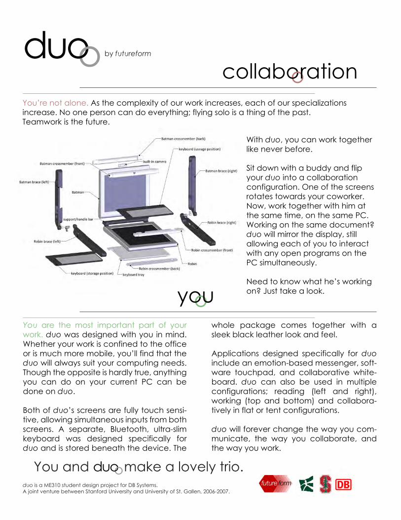
You’re not alone. As the complexity of our work increases, each of our specializations increase. No one person can do everything; flying solo is a thing of the past. Teamwork is the future.
collaboration
you
With duo, you can work together like never before.
Sit down with a buddy and flip your duo into a collaboration configuration. One of the screens rotates towards your coworker. Now, work together with him at the same time, on the same PC. Working on the same document? duo will mirror the display, still allowing each of you to interact with any open programs on the PC simultaneously.
Need to know what he’s working on? Just take a look.
You and make a lovely trio.duoduo is a ME310 student design project for DB Systems.A joint venture between Stanford University and University of St. Gallen, 2006-2007.
You are the most important part of your work. duo was designed with you in mind. Whether your work is confined to the office or is much more mobile, you’ll find that the duo will always suit your computing needs. Though the opposite is hardly true, anything you can do on your current PC can be done on duo.
Both of duo’s screens are fully touch sensi-tive, allowing simultaneous inputs from both screens. A separate, Bluetooth, ultra-slim keyboard was designed specifically for duo and is stored beneath the device. The
whole package comes together with a sleek black leather look and feel.
Applications designed specifically for duo include an emotion-based messenger, soft-ware touchpad, and collaborative white-board. duo can also be used in multiple configurations; reading (left and right), working (top and bottom) and collabora-tively in flat or tent configurations.
duo will forever change the way you com-municate, the way you collaborate, and the way you work.

Goals and Vision StatementThe original goal for the GM console project was todesign a new, exciting in-car information system thatprovides fresh content, is stylishly integrated, and hasan intuitive human-machine interface. Our visionbecame to develop a system for communicatinginformation that significantly reduces driver distractionand enhances driver enjoyment.
At the start of spring quarter, the Stanford and TUMteams decided to pursue complementary pathstowards achieving this vision. Each team developed aseparate system to be integrated into the samevehicle, allowing us to realize, test, and present moreconcepts.
The Stanford team designed, built, and integrated anLED lighting system into a Cadillac CTS that providessubtle, attractive visual cues for turn-by-turn navigationas well as mood lighting. The TUM team achieved asimilar result through a haptic system based onvibrating motors in the seat. Their visit in May allowedthem to install the system into the Cadillac CTS.
BackgroundLCD and touch screens have become commonfeatures in modern vehicles. While these devicesexpand the capabilities available to the driver andpassengers, their use often causes frustration,information overload, and unsafe distractions.Balancing complex capabilities with simple, intuitive,and user-friendly interaction modes has become asignificant challenge with these devices. Keeping thischallenge in mind, we have searched for ways toreduce the attention current consoles demand as wellas simplify the communication of information theypresent in order to make driving safer and moreenjoyable. Our solution: communicate the informationthrough alternative channels and enable the driver toabsorb it with no direct attention required.
Since many GM automobiles currently tend to appealto older individuals, this project also provides theopportunity to target a younger audience and help GMexpand its market among this demographic.
Stanford TeamAlan SleddLaura CrenwelgeAngelo SantiagoPrasad Akella (coach)
TUM TeamThomas SchmiedingerBenjamin OhmerManuel FluckRene OkoampahThomas Meiwald (coach)
ME310 2006-2007Spring QuarterDesign Abstract
General MotorsConsole Project
GM LiaisonsCem SaraydarMike AmesByron Shaw

Main navigational array of Stanford lighting systemthat communicates turn direction and distance to
turn through dynamic effects
Close-up of vibrating motor and detail of six motorinstallation locations of TUM in-seat vibration system
Final Deliverables
• Prototype Functionality• Turn-by-turn navigation• Haptic and visual channels of display• User-selected mood lighting
The following are what we will deliver at the end of this quarter:
• Testing• Qualitative user testing• Variety of Gen-Y testers• Report of results
• Documentation• Formal report• CAD files of prototype• Control software• Video of use and usage scenarios
Combined Stanford-TUM SystemSystem Design
• Lighting:• 6 in-car RGB LED arrays – 52 RGB LEDs total• 3 PhidgetLED 64 control boards• Custom-made PCBs for LED/Phidget communication
• Vibration:• 6 vibrating motors, sourced from a massage chair• Phidget motor controller commanding 3 relay switches
• General:• Powered by 12VDC vehicle supply• Control software integrating GPS data, mapping and routing capabilities, and lighting
and vibration effects• Simple and customizable control• USB connection to laptop running control software
Functions Tested• System intuitiveness, effectiveness• User light and vibration pattern preferences• User satisfaction
Test Results• Testing still in progress at publication
time of this document. Results will begiven in the final documentation toGeneral Motors.
1
4 2
5
6
3

Very Human Technology
[Team Stanford] Addala BhargavEric Bennett Ruka Sakurai DanielleSheehan [Coach] Bob Smith[Team Helsinki] Lasse Kåhre LauraLaaksonen Teemu Vaarakallio[Coach] Lauri Repokari [NokiaC o r p o r a t e L i a s o n s ] R a m i nVatanparast Vidya Setlur

SNAP IT when you see somethingworth commenting or you just wantto make your mark.
Create your Ki’i art and share it with others
Ki’i IT to draw your handwrittencomments and express your thoughtsand feelings.
SHARE IT with friends, family, orother people in the Ki’i community.
The stylus is never misplaced dueto its attachment to the devicethrough the use of magnets. Theuse of the stylus and the user’sfingertip allow the user to interactwith the device and easily switchthrough the search, view, and drawmodes.
The built-in camera is easy to usethrough the use of one-click.
The map mode allows you find Ki’iart around you or at a specificlocation through the use of Loki,Google Maps, and Flikr.
The draw mode interface allowsthe user to quickly change the brushsize, color, and transparency togive the right graphical effect inhandwritten comments andsketches.
User generated tags or keywordshelp recover specific Ki’i art forviewing.
Foldable color e-ink screenwith high resolution preventsglare during outside use.
Filtershelp the user browse throughmultiple photos based on wholeft the Ki’i art, the location it wasleft, and when it was left. Theseare automatically set during thedraw mode through a required“log-in”for users, WiFitriangulation to determine thelocation, and built-in time-stamps.
Portable design and sizeprotects the screen while fittinginto the user’s pocket.
Gear mechanismis used for opening and closingdevice without creasing thescreen.

Sponsor
Matsushita Electric Industrial, Ltd (Panasonic)
Sponsor LiaisonDeanna Wilkes-Gibbs
TKK, TaiK, TSE
Team MembersLilli PalastoKaisa ValkamaTimo VuoriKimmo Wihinen
CoachesLauri RepokariLaura GronroosLotta Hassi
Stanford University
Team MembersBrian BoggsDerrick JueJeamin KooWill McColl
CoachMachiel Van der Loos
Team Contact [email protected],http://e-mo.stanford.edu
ME310 2006-2007
How E-mo Works1) Receives user arousal level from third party sensor package2) Displays user’s own level to self via ambient LEDs3) Transmits user’s level to others4) Displays user’s level to others via unique vibratory patterns
VisionDeveloped as a platform for communicating invisible internal states, Team Panasonic Sensibles' Emo system explores the use of novel wearable technologies in promoting social and emotional awareness to increase the quality of social interactions. Specifically, our device enhances users’ ability to infer internal states by making clearly visible (1) one’s own level of arousal and (2) the arousal levels of others. By making invisible states visible, E-mo enables users to systematically monitor, gain better insight into, and improve how they communicate and interact with others.
Fig1. E-Mo Wristband
1
23
4
Fig2. E-mo in action.

ME310 2006-2007
Internal Components
Background and Solution PathThe need to maintain healthy relationships and interactions is intrinsic. To this end, accurate perception of and response to the behaviors of others is paramount in achieving a high level of social well-being – miscommunications often arise from misinterpretation of social signals. An individual’s ability to master social skills is directly correlated with success in areas such as family, school, and business (Peterson). While face-to-face, we infer the internal states of others from their assumed external behavioral, physiological, and auditory signals. However, these often socially construed expressions rarely accurately reflect their respective states (Lisetti).
Design Specifications1) accurately receive arousal level of user in real-time2) transmits own arousal levels to self via visual LED display3) transmits arousal levels to others via vibrotactile stimulation5) wearable for seamless integration into everyday life
Fig 3. 1) Polycarbonate Cover. 2) Polyurethane Body. 3) Digital Time Display. 4) Tri-Color LED. 5) Polymer Li-Ion Battery. 6) Vibrating Pancake Motor. 7) Wireless Chip. 8) Printed Circuit Board.
E-mo communicates three unique signals representative of low (lepo), normal (rauha), and elevated (kiihko) levels of arousal.In combination with natural mechanisms, E-mo enhances a user’s ability to better infer the internal states of others and, subsequently, to respond in a manner more conducive to promoting healthy relationships.
Sensor/E-mo Function Flow
Fig5. Internal states are inferred from social construed, external expressions.
Lisetti, Christine L., and Fatma Nasoz. "Using Noninvasive Wearable Computers to Recognize Human Emotions From Physiological Signals." EURASIP Journal on Applied Signal Processing Vol. 11 (2004): 1672-1687.Peterson, Christopher, and Martin E. P. Seligman. "Strength of Character and Well-Being." Journal of Social and Clinical Psychology, Vol. 23 No. 5 (2004): 603-619.
Red
Fig6. E-mo’s Visual (LED) and vibrotactile (three vibrating motors) display modalities of each arousal level.
M1
M2
M3
M1
M2
M3
Green Blue
Lepo Rauha Kiihko
18
7 65
4 3
2
Third Party Sensor
interpret data
capture data
transmit
E-mo
VisualDisplay
VibrotactileDisplay
transmit
Fig4. A third party sensor package operates independently collecting and interpreting user data. E-mo serves as a platform, receiving the sensor output and displaying it using novel, real-time visual and vibrotactile signals. This allows E-mo the versatility to adopt alternate implementations in the future.
User

Page 1 of 2
Stanford University - 310, 2006-2007 Team Based Design with Corporate Partners
hinkhink
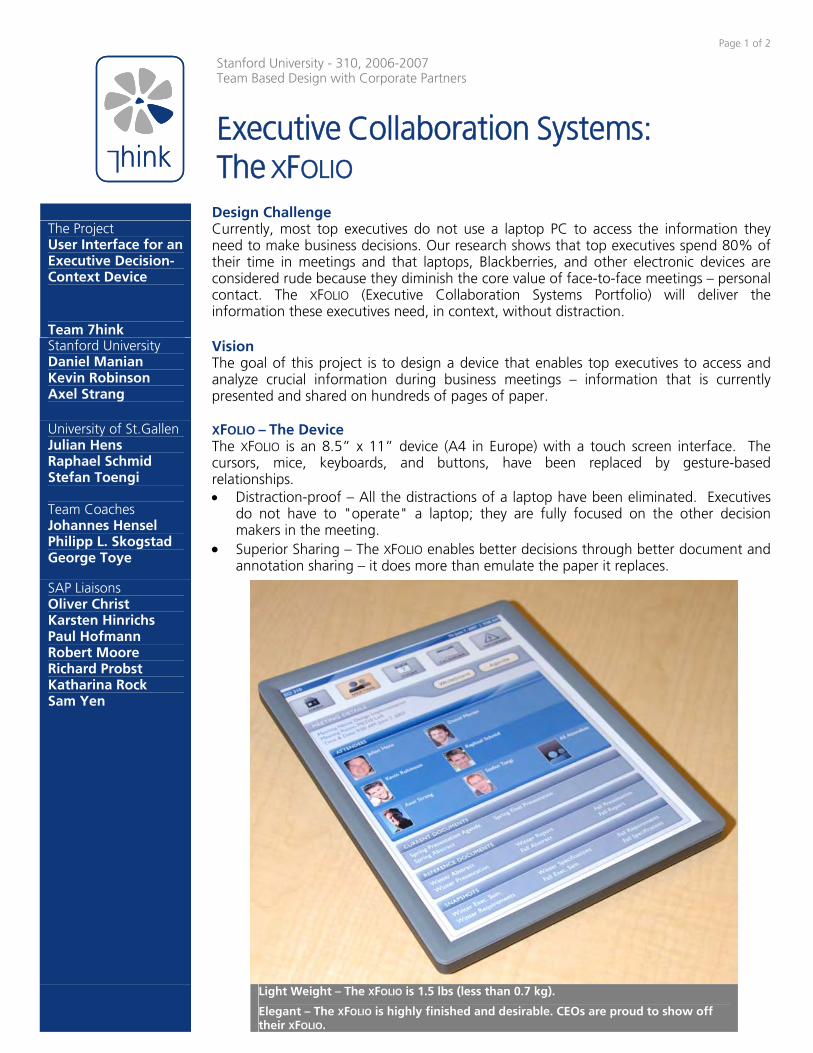
Executive Collaboration Systems: The XFOLIO
The Project User Interface for an Executive Decision-Context Device Team 7hink
Design Challenge Currently, most top executives do not use a laptop PC to access the information they need to make business decisions. Our research shows that top executives spend 80% of their time in meetings and that laptops, Blackberries, and other electronic devices are considered rude because they diminish the core value of face-to-face meetings – personal contact. The XFOLIO (Executive Collaboration Systems Portfolio) will deliver the information these executives need, in context, without distraction.
Stanford University Daniel Manian Kevin Robinson Axel Strang
Vision The goal of this project is to design a device that enables top executives to access and analyze crucial information during business meetings – information that is currently presented and shared on hundreds of pages of paper.
University of St.Gallen Julian Hens Raphael Schmid Stefan Toengi Team Coaches Johannes Hensel Philipp L. Skogstad George Toye
XFOLIO – The Device The XFOLIO is an 8.5” x 11” device (A4 in Europe) with a touch screen interface. The cursors, mice, keyboards, and buttons, have been replaced by gesture-based relationships. • Distraction-proof – All the distractions of a laptop have been eliminated. Executives
do not have to "operate" a laptop; they are fully focused on the other decision makers in the meeting.
• Superior Sharing – The XFOLIO enables better decisions through better document and annotation sharing – it does more than emulate the paper it replaces.
SAP Liaisons Oliver Christ Karsten Hinrichs Paul Hofmann Robert Moore Richard Probst Katharina Rock Sam Yen
Light Weight – The XFOLIO is 1.5 lbs (less than 0.7 kg).
Elegant – The XFOLIO is highly finished and desirable. CEOs are proud to show off their XFOLIO.

Page 2 of 2
Fig. 1: Current Meeting Screen
Fig. 2: Tiling Two XFOLIOS
Fig. 3: Sending Document with Gesture Shortcut
Superior Functionality A Current Meeting screen (Figure 1) is prepared by the executive’s assistant for every meeting, providing all the relevant information at the executive’s fingertips. From this menu executives can:
• View attendees’ profiles • Open the agenda and documents to view and make annotations • Send documents to meeting attendees • View page-synchronized documents with meeting attendees
Tiling (Figure 2) additional XFOLIOS allows users to simultaneously:
• View non-contiguous pages in a document • View multiple documents • View the same content with larger fonts and images
Gesture Shortcuts enable public coordination of sharing activities with everyone in the meeting:
• Send Documents to all attendees (Figure 3) Sender ‘tosses’ a file by shaking his or her XFOLIO Recipients ‘catch’ the file by shaking their XFOLIOs
• View Page-Synchronized Documents with all attendees (Figure 4) Enables real-time communal annotation and information
manipulation on document pages Host initiates connection request by tilting his or her XFOLIO on its
long edge Executives who copy the gesture with their XFOLIOS will open a
connection enabling them to collaborate with the host User Feedback • “I’ve wanted this for years.” – Michael Kinsley, founding editor of online
journal Slate • “This is great stuff. I’ll be your customer.” – Professor Thomas Kenny,
DARPA program manager, ME Design Division, Stanford University • “The docking is cool. [The gesture-based document transfer] is totally
great… being somewhat physical in meetings kind of brings them alive.” – Patty Stonesifer, CEO, Bill and Melinda Gates Foundation
• “[To] have all of that [information on the device] instead of on all of my handwritten notes and folders… would be very useful.” – Professor Siegfried Hecker, former director Los Alamos National Laboratory, Professor of Management Science & Engineering, Stanford University
• “It’s amazing. It’s fantastic. [I would like it], absolutely… I think it would be really good.” – Lorraine Theodorakakis, Professor Siegfried Hecker’s assistant
• “[The team] takes the tablet PC and they cover up all the functions so you can't use them, and then what they give back to you are the 10-20 most important things you might want to use in a meeting. And you access them through touch on the screen – finger, no tool – and gestures.” – Professor Larry Leifer, ME Design Division, Stanford University
Design Approach • Learn executives’ unaddressed needs from researching, interviewing and
observing top executives and their assistants • Know current and emerging technological solutions • Focus on in-meeting situations • Understand why paper is so good in meetings • Iteratively prototype features to hone in on superior functionalities University Partners Corporate Partner Fig. 4: Viewing Page-Synced
Document with Gesture Shortcut

1 of 2
VW Intelligent Display
Corporate Liaisons/ Sponsor
UNAM Team
Stanford University Team
Mike Ingalls Ji Lee
Corina Yen
Rene Bustamante
Maria Esther Mejía
Daniel Rosario
Brian Ng
VW Electronics Research Lab
Coaches
Uri Geva Vicente Borja Luis Equihua
Alejandro Ramirez Arturo Treviño
Vision and Goals
VW Intelligent Display team aims to create an integrated system of displays that pre-sents information where and when needed with controls that are reachable and intui-tive. By bringing the display and controls closer to the driver within easy view and reach, interaction with the display is integrated into the driving experience without dis-tracting the user from the primary task of safe driving. Additional displays along the driver’s side A-pillar enables the driver to view dynamic information such as turn-by-turn directions and vehicle warnings through his/her peripheral vision. The objective of the VW Intelligent Display project is to provide an innovative solution to the problems found in current in-car displays in a way that clearly reflects Volkswagen’s brand im-age.
Background Since the introduction of automotive GPS navigation systems about twenty-five years ago, displays have become increasingly commonplace in cars. They have evolved from GPS-only into multi-function devices. However, their form factor and position have not developed overtime, and the majority of displays remain fixed in the center console. Even to this day, car manufacturers struggle to incorporate displays into cars in a way that is both comfortably viewable and reachable for direct input. lkjhasldkjhasdfk The current low position of the display in the center console requires the user to bend forward and sideways to reach the display. Fingerprints visible on the display surface after touch-screen input are also common problems. In addition, current display posi-tions require the driver to significantly shift his/her focal distance from the road to view the screen, thereby increasing distraction. Furthermore, the controls for current displays are hard to reach, and the interfaces are unintuitive, requiring significant attention from the driver.
Current VW Passat Interior has a single center-mounted display
Design Requirements
Requirement Required Value
Viewable without significant devia-tion in the driver’s gaze away from the road.
< 1.5 sec of looking-away from the road per glance.
Within reach when user is in normal driving position.
Touch-screen usable without bending forward and sideways. Display is within 20.4 in (average arm length) of driver seat back.
Has stowed-away and in-use posi-tions.
Display aesthetically and stylistically inte-grated into the Passat interior when in use and when not in use.
Display surface not occluded by fingerprints and dirt.
Display clean enough that it is viewable and not aesthetically unpleasant.

2 of 2
User Interaction
VW Intelligent Display
Engineering 310. Project Abstract
Solution Features and Functions
Feature Function
Main deployable center-mounted display Current car displays are hard to reach and view while driv-ing. VW Intelligent display is mounted higher on the center console and the deployment mechanism brings the display close to the driver
Intuitive control wheel on the right edge of the display to augment touch-screen input (not visible in the image above)
Interaction with touch screen input requires much visual atten-tion from the driver. The control wheel with detents can re-duce the driver’s look-away time from the road.
Memory function for user-defined display orientation The display orientation can be adjusted by the user with pan/tilt control buttons and up to two different orientations can be stored for next time use.
Hidden cleaning mechanism for display surface Fingerprints cause view-ability problems in current displays. The cleaning mechanism whipes the display surface every time the display is used.
Auxiliary A-pillar displays Additional displays along the driver’s side A-pillar enable the driver to view dynamic information such as turn-by-turn directions and vehicle warnings through his/her peripheral vision.
A-pillar Displays Panel
hides display when not in use
Deployment Mechanism
4 inches from surface dashboard
Display
-pan/tilt -orientation memory function -control wheel -touch screen
Dashboard
Cleaning Mechanism
wipes the display surface to clean finger-prints/dust off.
A driver gets into his Passat, and inserts the car
key.
The display panel on the center console opens up.
The display comes out of the dashboard to an
easily reachable position.
The driver adjusts the display orientation using
the pan/tilt control buttons.
Once the display is in a good viewable position, a “set”
button is pressed to store the current display orientation for
next time use.
The driver interacts with audio, climate, GPS, and internet functions on the
display
Once the driver reaches a destination, the engine is
turned off.
The display adjusts itself to the original orientation and goes back into the
dashboard.
The panel on the dashboard closes over the
display.
The cleaning mechanism activates and cleans the
display surface.


