SINAMICS S Reactive power - … · Reactive power compensation with ... transformers and switchgear...
56
SINAMICS S Reactive power compensation with Active Line Module and DCC SINAMICS S120/S150 https://support.industry.siemens.com/cs/ww/en/view/57886317 Siemens Industry Online Support
Transcript of SINAMICS S Reactive power - … · Reactive power compensation with ... transformers and switchgear...

SINAMICS S Reactive power compensation with Active Line Module and DCC
SINAMICS S120/S150
https://support.industry.siemens.com/cs/ww/en/view/57886317
Siemens Industry Online Support

Legal information
Reactive power compensation Entry-ID: 57886317, V4.0, 01/2018 2
S
iem
en
s A
G 2
01
8 A
ll ri
gh
ts r
ese
rve
d
Legal information Use of application examples
Application examples illustrate the solution of automation tasks through an interaction of several components in the form of text, graphics and/or software modules. The application examples are a free service by Siemens AG and/or a subsidiary of Siemens AG (“Siemens”). They are non-binding and make no claim to completeness or functionality regarding configuration and equipment. The application examples merely offer help with typical tasks; they do not constitute customer-specific solutions. You yourself are responsible for the proper and safe operation of the products in accordance with applicable regulations and must also check the function of the respective application example and customize it for your system.
Siemens grants you the non-exclusive, non-sublicensable and non-transferable right to have the application examples used by technically trained personnel. Any change to the application examples is your responsibility. Sharing the application examples with third parties or copying the application examples or excerpts thereof is permitted only in combination with your own products. The application examples are not required to undergo the customary tests and quality inspections of a chargeable product; they may have functional and performance defects as well as errors. It is your responsibility to use them in such a manner that any malfunctions that may occur do not result in property damage or injury to persons.
Disclaimer of liability Siemens shall not assume any liability, for any legal reason whatsoever, including, without limitation, liability for the usability, availability, completeness and freedom from defects of the application examples as well as for related information, configuration and performance data and any damage caused thereby. This shall not apply in cases of mandatory liability, for example under the German Product Liability Act, or in cases of intent, gross negligence, or culpable loss of life, bodily injury or damage to health, non-compliance with a guarantee, fraudulent non-disclosure of a defect, or culpable breach of material contractual obligations. Claims for damages arising from a breach of material contractual obligations shall however be limited to the foreseeable damage typical of the type of agreement, unless liability arises from intent or gross negligence or is based on loss of life, bodily injury or damage to health. The foregoing provisions do not imply any change in the burden of proof to your detriment. You shall indemnify Siemens against existing or future claims of third parties in this connection except where Siemens is mandatorily liable.
By using the application examples you acknowledge that Siemens cannot be held liable for any damage beyond the liability provisions described.
Other information Siemens reserves the right to make changes to the application examples at any time without notice. In case of discrepancies between the suggestions in the application examples and other Siemens publications such as catalogs, the content of the other documentation shall have precedence.
The Siemens terms of use (https://support.industry.siemens.com) shall also apply.
Security information Siemens provides products and solutions with industrial security functions that support the secure operation of plants, systems, machines and networks.
In order to protect plants, systems, machines and networks against cyber threats, it is necessary to implement – and continuously maintain – a holistic, state-of-the-art industrial security concept. Siemens’ products and solutions constitute one element of such a concept.
Customers are responsible for preventing unauthorized access to their plants, systems, machines and networks. Such systems, machines and components should only be connected to an enterprise network or the internet if and to the extent such a connection is necessary and only when appropriate security measures (e.g. firewalls and/or network segmentation) are in place.
For additional information on industrial security measures that may be implemented, please visit https://www.siemens.com/industrialsecurity.
Siemens’ products and solutions undergo continuous development to make them more secure. Siemens strongly recommends that product updates are applied as soon as they are available and that the latest product versions are used. Use of product versions that are no longer supported, and failure to apply the latest updates may increase customer’s exposure to cyber threats.
To stay informed about product updates, subscribe to the Siemens Industrial Security RSS Feed at: http://www.siemens.com/industrialsecurity.

Table of contents
Reactive power compensation Entry-ID: 57886317, V4.0, 01/2018 3
S
iem
en
s A
G 2
01
8 A
ll ri
gh
ts r
ese
rve
d
Table of contents Legal information ......................................................................................................... 2
1 Application description ..................................................................................... 4
1.1 Overview............................................................................................... 4 1.2 Methods of closed-loop control ............................................................ 6 1.2.1 Reactive power control ......................................................................... 6 1.2.2 Displacement factor control (𝐜𝐨𝐬𝛗𝟏control) ......................................... 7
2 Hardware ............................................................................................................ 8
2.1 Overview hardware structure ............................................................... 8 2.2 Description of the functionality ............................................................. 9 2.3 Hardware and software components used......................................... 11 2.4 Notes for sizing ................................................................................... 12
1 Commissioning the application ..................................................................... 18
1.1 Commissioning the cos phi-display .................................................... 18 1.2 Installing the DCC charts.................................................................... 20 1.3 Interface adjustment ........................................................................... 21 1.4 Information about processing time ..................................................... 22
2 Program description ........................................................................................ 23
2.1 Function charts ................................................................................... 23 2.2 Parameter list ..................................................................................... 32 2.2.1 Basic structure of parameter descriptions .......................................... 32 2.2.2 Parameter list ..................................................................................... 41 2.3 Faults and alarms ............................................................................... 54
3 Appendix .......................................................................................................... 55
3.1 Service and Support ........................................................................... 55 3.2 Application Support ............................................................................ 56 3.3 Links and Literature ............................................................................ 56 3.4 Change documentation ...................................................................... 56

1 Application description
Reactive power compensation Entry-ID: 57886317, V4.0, 01/2018 4
S
iem
en
s A
G 2
01
8 A
ll ri
gh
ts r
ese
rve
d
1 Application description
1.1 Overview
Introduction
In industrial plants and systems, most of the loads connected to the line supply require both active and reactive power. The resulting apparent power S must be provided by the utility company and the power generating company. In this case, the reactive power increases the apparent power demand of the industrial plant. This means additional costs for the power supply equipment such as generators, transformers and switchgear as well as higher losses in the power transmission.
For that reason, utility companies usually charge customers for their reactive power consumption in addition.
However, if the required reactive power is already compensated at the line connection point, frequently the apparent power requirement can be significantly reduced. This also avoids having to pay the costs associated for providing reactive power:
Description of the application
The following diagram is obtained for the load at the line connection point if there is no compensation:
Table 1-1
Vector diagram when drawing non-compensated inductive reactive power
Vector diagram when drawing non-compensated capacitive reactive power
In many drive applications the "SINAMICS S Active Line Module", self-commutated infeed/regenerative feedback unit, are used to feed the motor inverters. These devices can compensate their own reactive current consumption, resulting in a line power factor of 1.0. In addition it is possible to adjust an additional reactive current setpoint in either inductive or capacitive direction. As a consequence, the reactive power demand of other loads connected to the same line connection point can be provided.
In conjunction with a measuring transducer used at the common line connection point to measure the reactive power, this application allows the reactive power occurring in the fundamental oscillation to be compensated.
1 Application description
Reactive power compensation Entry-ID: 57886317, V4.0, 01/2018 5
S
iem
en
s A
G 2
01
8 A
ll ri
gh
ts r
ese
rve
d
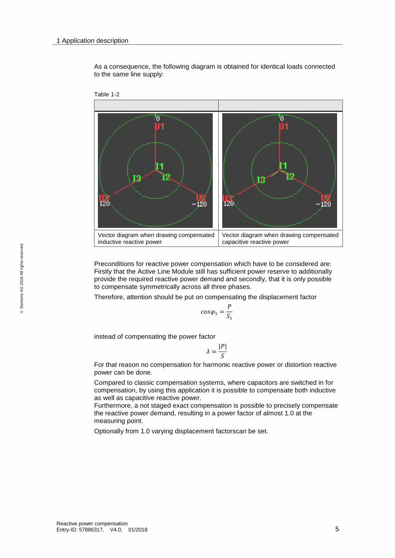
As a consequence, the following diagram is obtained for identical loads connected to the same line supply:
Table 1-2
Vector diagram when drawing compensated inductive reactive power
Vector diagram when drawing compensated capacitive reactive power
Preconditions for reactive power compensation which have to be considered are: Firstly that the Active Line Module still has sufficient power reserve to additionally provide the required reactive power demand and secondly, that it is only possible to compensate symmetrically across all three phases.
Therefore, attention should be put on compensating the displacement factor
𝑐𝑜𝑠𝜑1 =𝑃
𝑆1
instead of compensating the power factor
𝜆 =|𝑃|
𝑆
For that reason no compensation for harmonic reactive power or distortion reactive power can be done.
Compared to classic compensation systems, where capacitors are switched in for compensation, by using this application it is possible to compensate both inductive as well as capacitive reactive power. Furthermore, a not staged exact compensation is possible to precisely compensate the reactive power demand, resulting in a power factor of almost 1.0 at the measuring point.
Optionally from 1.0 varying displacement factorscan be set.
1 Application description
Reactive power compensation Entry-ID: 57886317, V4.0, 01/2018 6
S
iem
en
s A
G 2
01
8 A
ll ri
gh
ts r
ese
rve
d
1.2 Methods of closed-loop control
1.2.1 Reactive power control
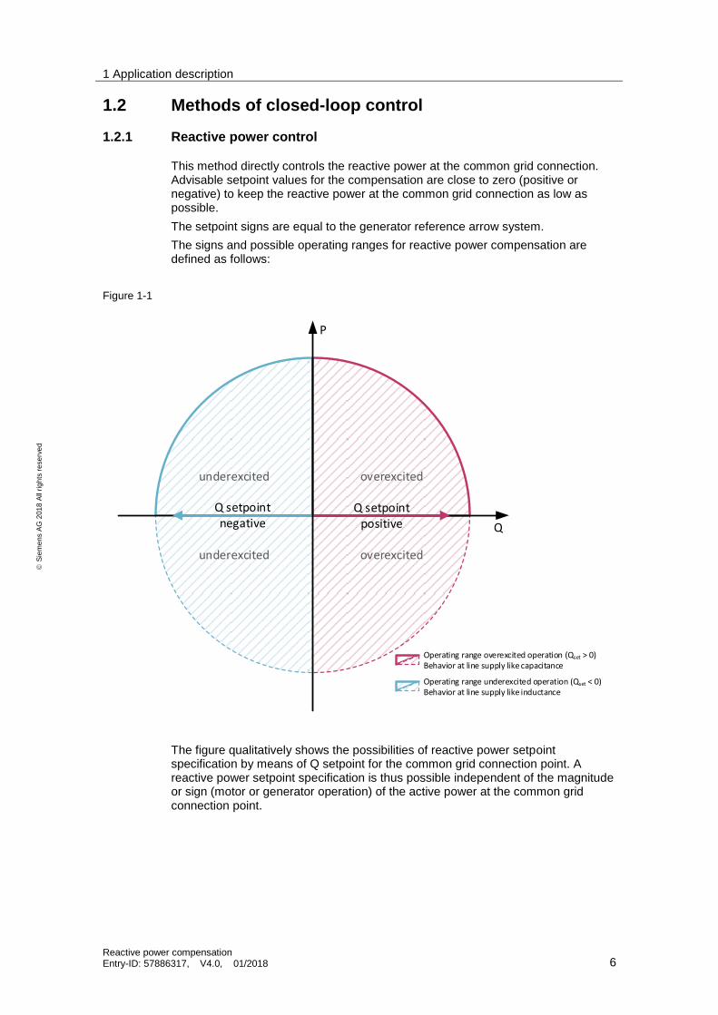
This method directly controls the reactive power at the common grid connection. Advisable setpoint values for the compensation are close to zero (positive or negative) to keep the reactive power at the common grid connection as low as possible.
The setpoint signs are equal to the generator reference arrow system.
The signs and possible operating ranges for reactive power compensation are defined as follows:
Figure 1-1
underexcited
underexcited overexcited
overexcited
Q
Operating range overexcited operation (Qset > 0)Behavior at line supply like capacitance
Operating range underexcited operation (Qset < 0)Behavior at line supply like inductance
Q setpointpositive
P
The figure qualitatively shows the possibilities of reactive power setpoint specification by means of Q setpoint for the common grid connection point. A reactive power setpoint specification is thus possible independent of the magnitude or sign (motor or generator operation) of the active power at the common grid connection point.

1 Application description
Reactive power compensation Entry-ID: 57886317, V4.0, 01/2018 7
S
iem
en
s A
G 2
01
8 A
ll ri
gh
ts r
ese
rve
d
1.2.2 Displacement factor control (𝐜𝐨𝐬𝛗𝟏control)
This method controls the active power in relation to the apparent power at the common line connection. Hereby the reactive power is controlled indirectly.
This control mode provides the possibility to specify variable setpoints for cosφ1, e.g. to implement requirements of the energy suppliers.
The setpoint signs are equal to the generator reference arrow system respectively matches the use in grid standards (e.g. VDE-AR-N 4105).
The signs and possible operating ranges for the control of cosφ1 are defined as follows:
Figure 1-2
underexcited
underexcited overexcited
overexcited
P
Q
Operating range overexcited operation (cos ϕ1 < 0)
Behavior at line supply like capacitance
Operating range underexcited operation (cos ϕ1 > 0)
Behavior at line supply like inductance
Invalid range (|cos ϕ1| < 0,3)
cos ϕ
1 –
se
tpo
int
neg
ati
veϕ
cos ϕ
1 –
set
po
int
po
siti
ve
cos ϕ
1 – setp
oin
tn
egativeϕ
cos ϕ
1 – setpo
int
po
sitive
Invalid range (|P| < Threshold)
The figure qualitatively shows the possibilities of the cosφ1 setpoint specification for the common grid connection point.
A setpoint specification is thus dependent of the magnitude of the active power at the common grid connection point - the control is active only from an adjustable active power threshold. In addition, the specification of the setpoint is limited to
values −1 ≤ 𝑐𝑜𝑠𝜑1 ≤ −0,3 and 0,3 ≤ 𝑐𝑜𝑠𝜑1 ≤ 1.
A setpoint specification is independent of the sign (motor or generator operation) of the active power at the common grid connection point.

2 Hardware
Reactive power compensation Entry-ID: 57886317, V4.0, 01/2018 8
S
iem
en
s A
G 2
01
8 A
ll ri
gh
ts r
ese
rve
d
2 Hardware
2.1 Overview hardware structure
Schematic
The most important components of the solution are schematically shown in the following figure.
Figure 2-1
Required know-how
Basic knowledge about the SINAMICS drive system, as well as handling the STARTER software and DCC (Drive Control Chart) are required.
common line
connection
reactive power loads
drive line-up consisting
of an Active Interface
Module, Active Line
Module, Motor Module
and motor
CU320-2
Voltage
Sensing Module
VSM10
DRIVE-CLiQ

2 Hardware
Reactive power compensation Entry-ID: 57886317, V4.0, 01/2018 9
S
iem
en
s A
G 2
01
8 A
ll ri
gh
ts r
ese
rve
d
2.2 Description of the functionality
Description of the application
A DCC-based closed-loop control is the core function of the reactive power compensation application. It controls the reactive current generated by the Active Line Module, so that at the measuring point – generally at the common line connection point of the system to be compensated – a reactive current of zero and
therefore a line supply power factor (cos 1) of 1.0 is obtained. It is also possible to set a reactive current setpoint for the measuring point that is not zero. The application offers the possibility of controlling an input reactive power or the power factor.
Advantages of this application
The solution presented here offers the following advantages:
Depending on the power reserve and the reactive current to be compensated, it is not necessary to use an additional, complex compensation system.
Capacitive reactive powers, which for example occur in conjunction with frequency converters, can also be easily compensated.
There is no additional control (PLC) required, respectively no changes have to be made at the communication to the control system.
Operating the Active Infeed with a power factor cosφ <1
Is the Active Infeed, whose reactive current is parameterizable in the firmware, operated with a power factor cosφ <1, power losses of the Active Line Module are increasing. Therefore the current has to be reduced according to the following derating-characterizations. There a different deratings depending on the Active Infeed’s design. The Application identifies the design and uses the correct derating-characterization automatically.
Figure 2-2: Derating Active Line Module Booksize up to 80 kW
admissible line current
1,00
0,95
0,90
0,85
0,80
0,75
0,00
cosφ1,00 0,80 0,60 0,40 0,20 0,00

2 Hardware
Reactive power compensation Entry-ID: 57886317, V4.0, 01/2018 10
S
iem
en
s A
G 2
01
8 A
ll ri
gh
ts r
ese
rve
d
Figure 2-3: Derating Active Line Module Chassis and Booksize up to 120 kW
1,00
0,95
0,90
0,85
0,80
0,75
0,00
cosφ1,00 0,80 0,60 0,40 0,20 0,00
admissible line current
2 Hardware
Reactive power compensation Entry-ID: 57886317, V4.0, 01/2018 11
S
iem
en
s A
G 2
01
8 A
ll ri
gh
ts r
ese
rve
d
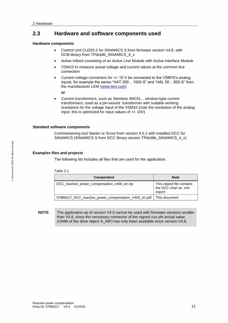
2.3 Hardware and software components used
Hardware components
Control Unit CU320-2 for SINAMICS S from firmware version V4.8, with DCB-library from TPdcblib_SINAMICS_4_x
Active Infeed consisting of an Active Line Module with Active Interface Module
VSM10 to measure actual voltage and current values at the common line connection
Current-voltage-converters for +/- 10 V be connected to the VSM10’s analog inputs, for example the series “HAT 200 .. 1500-S” and “HAL 50 .. 600-S” from the manufacturer LEM (www.lem.com)
or
Current transformers, such as Siemens 4NC51 .. window-type current transformers, used as a pin-wound transformer with suitable working resistance for the voltage input of the VSM10 (note the resolution of the analog input, this is optimized for input values of +/- 10V)
Standard software components
Commissioning tool Starter or Scout from version 4.5.1 with installed DCC for SINAMICS (SINAMICS S from DCC library version TPdcblib_SINAMICS_4_x)
Examples files and projects
The following list includes all files that are used for the application.
Table 2-1
Compontent Note
DCC_reactive_power_compensation_v400_en.zip This zipped file contains the DCC chart as .xml export
57886317_DCC_reactive_power_compensation_V400_en.pdf This document
NOTE The application as of version V4.0 cannot be used with firmware versions smaller than V4.8, since the necessary connector of the signed cos phi actual value (r3496 of the drive object A_INF) has only been available since version V4.8.

2 Hardware
Reactive power compensation Entry-ID: 57886317, V4.0, 01/2018 12
S
iem
en
s A
G 2
01
8 A
ll ri
gh
ts r
ese
rve
d
2.4 Notes for sizing
When determining how much reactive power can be provided by the Active Line Module for the grid, the following aspects have to be taken into account.
Voltage load
It should be noted that the reactive power compensation should be made at the same voltage level to which the converter is connected to. A reactive power compensation in a higher voltage level could mean that the line voltage at the converter connection point is raised, resulting in an overvoltage shutdown of the converter itself. Further, there could be a potential danger due to a faster aging of the motor insulation system as a result of the higher voltage. When engineering the system, it should therefore be ensured that the maximum DC link voltage for 400V devices should not exceed a permanent value of 720V; for 690V devices, a value of 1080V.
Load duty cycles
If the loads connected to the line supply require high levels of reactive powers periodically, then the power cycling capability derating (derating factor kIGBT‘) must be taken into account the same as for the corresponding Motor Modules. However, this is only required if the load duty cycle deviates from the standard duty cycle, i.e. if the value Δ I is greater than 1.5 and/or the load duty cycle is shorter than 300s. You can find more detailed information in the SINAMICS Low-Voltage engineering manual in the "Load duty cycles" section.
Conductor cross-sections
For the cabinet units SINAMICS S150, fuses and cable cross sections are recommended in the documentation. These recommendations are selected based on the type and rating of the motors to be connected; and the line currents that are obtained, assuming that the ALM is only drawing active power and therefore active current according to its factory setting. As a consequence, these values are not equivalent with the currents of the chassis format ALMs used in the S150. If the reactive current is determined from the rated currents of the Active Line Modules and the required active current of the Motor Modules, the required cable cross-sections must be observed carefully.
This is especially important at low power ratings. Another important issue here is that the ALM is not the limiting component, but the fuse, which is recommended. As a consequence, after determining the reactive power that is available, the absolute current should also be determined to ensure that the recommended fuse is not overloaded. The ALMs used in the converter cabinet units together with their lineside rated currents are listed in the following table.

2 Hardware
Reactive power compensation Entry-ID: 57886317, V4.0, 01/2018 13
S
iem
en
s A
G 2
01
8 A
ll ri
gh
ts r
ese
rve
d
Table 2-2
SINAMICS S150
Voltage level 380V to 480V
Power Motor Module [kW] Power ALM [kW] Rated Input Current ALM [A]
110 132 210
132 132 210
160 235 380
200 235 380
250 300 490
315 380 605
400 500 840
450 500 840
560 630 985
710 900 1405
Voltage level 500V to 690V
Power Motor Module [kW] Power ALM [kW] Rated Input Current ALM [A]
75 150 140
90 150 140
110 150 140
132 150 140
160 330 310
200 330 310
250 330 310
315 330 310
400 560 575
450 560 575
560 560 575
710 800 735
800 1100 1025
900 1100 1025
1000 1100 1025
1200 1400 1270
The overview is only applicable if option L04 was not selected.

2 Hardware
Reactive power compensation Entry-ID: 57886317, V4.0, 01/2018 14
S
iem
en
s A
G 2
01
8 A
ll ri
gh
ts r
ese
rve
d
Determining reactive power
At the Active Line Module there is, according to its factory settings, no external setpoint set for a reactive current. Thereby the Active Line Module only provides the reactive current which is needed in the Clean Power Filter at the corresponding Active Interface Module. In this way, the Active Infeed or rather the converter only draws active power from the grid.
Using the DCC chart, an additional setpoint channel is interconnected which results in an additional reactive current, feed from the converter. As a consequence a basic fundamental power factor of cos φ < 1 occurs on the grid side.
If the Active Line Module is operated with a basic fundamental power factor of cos φ < 1 then losses in the Active Line Module increase as a result of the modulation system used. For that reason, the permissible input current of the Active Line Module must be reduced, based on the rated input current.
The values should be taken from the following derating characteristic. The first two characteristics are applicable for Chassis format devices as well as for cabinet units; the last two characteristics are valid for Booksize format devices.
Figure 2-4: Derating characteristic for ALM in Chassis and Booksize with 120 kW format
1,00
0,95
0,90
0,85
0,80
0,75
0,00
cosφ1,00 0,80 0,60 0,40 0,20 0,00
admissible line current
2 Hardware
Reactive power compensation Entry-ID: 57886317, V4.0, 01/2018 15
S
iem
en
s A
G 2
01
8 A
ll ri
gh
ts r
ese
rve
d
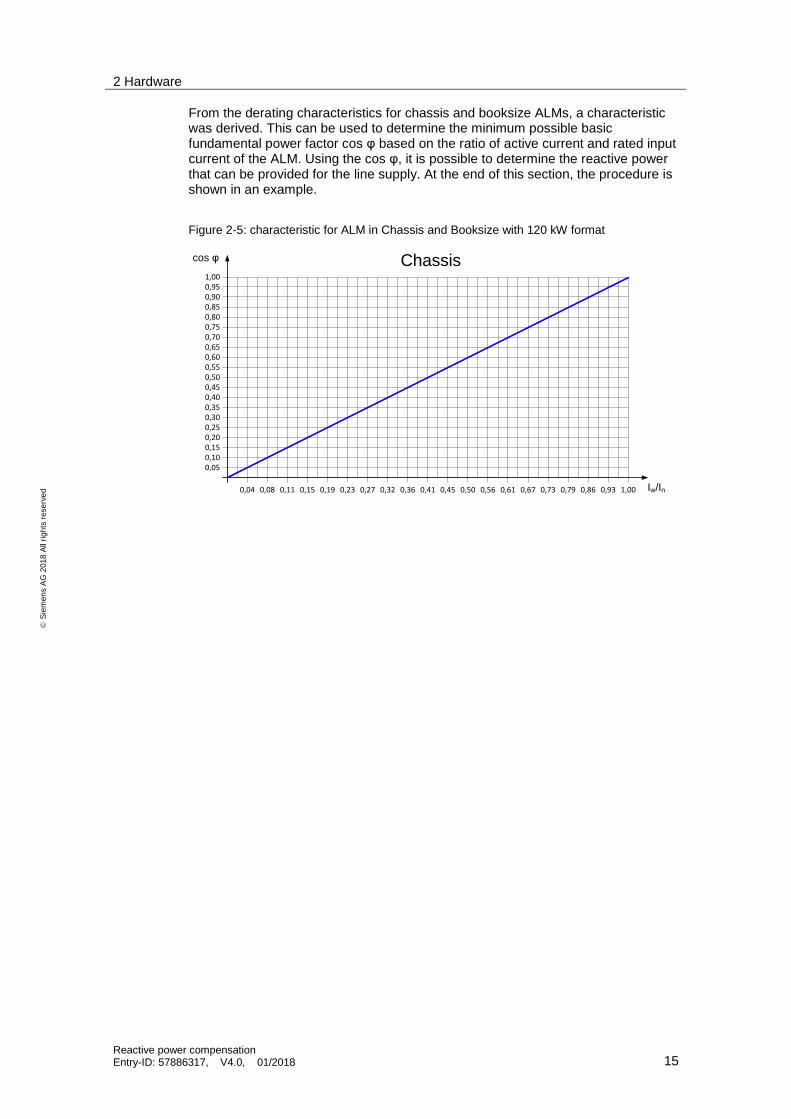
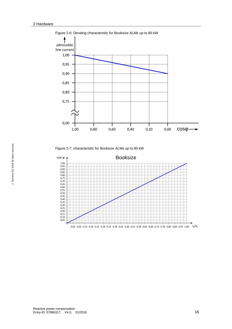
From the derating characteristics for chassis and booksize ALMs, a characteristic was derived. This can be used to determine the minimum possible basic fundamental power factor cos φ based on the ratio of active current and rated input current of the ALM. Using the cos φ, it is possible to determine the reactive power that can be provided for the line supply. At the end of this section, the procedure is shown in an example.
Figure 2-5: characteristic for ALM in Chassis and Booksize with 120 kW format
cos φ
0,05
Iw/In
0,10
0,950,900,850,800,750,700,650,600,550,500,450,400,350,300,250,200,15
1,00
0,04 0,08 0,11 0,15 0,19 0,23 0,27 0,32 0,36 0,41 0,45 0,50 0,56 0,61 0,67 0,73 0,79 0,86 0,93 1,00
Chassis
2 Hardware
Reactive power compensation Entry-ID: 57886317, V4.0, 01/2018 16
S
iem
en
s A
G 2
01
8 A
ll ri
gh
ts r
ese
rve
d
Figure 2-6: Derating characteristic for Booksize ALMs up to 80 kW
Figure 2-7: characteristic for Booksize ALMs up to 80 kW
cos φ
0,05
Iw/In
0,10
0,950,900,850,800,750,700,650,600,550,500,450,400,350,300,250,200,15
1,00
Booksize
0,05 0,09 0,14 0,18 0,23 0,28 0,33 0,38 0,43 0,48 0,53 0,58 0,63 0,68 0,73 0,78 0,84 0,89 0,95 1,00
admissible line current
1,00
0,95
0,90
0,85
0,80
0,75
0,00
cosφ1,00 0,80 0,60 0,40 0,20 0,00
2 Hardware
Reactive power compensation Entry-ID: 57886317, V4.0, 01/2018 17
S
iem
en
s A
G 2
01
8 A
ll ri
gh
ts r
ese
rve
d
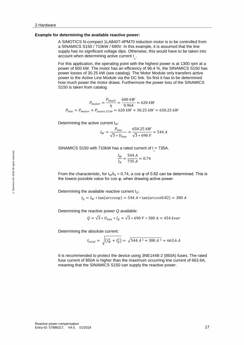
Example for determining the available reactive power:
A SIMOTICS N-compact 1LA8407-4PM70 induction motor is to be controlled from a SINAMICS S150 / 710kW / 690V. In this example, it is assumed that the line supply has no significant voltage dips. Otherwise, this would have to be taken into account when determining active current I
W
.
For this application, the operating point with the highest power is at 1300 rpm at a power of 600 kW. The motor has an efficiency of 96.4 %, the SINAMICS S150 has power losses of 30.25 kW (see catalog). The Motor Module only transfers active power to the Active Line Module via the DC link. So first it has to be determined how much power the motor draws. Furthermore the power loss of the SINAMICS S150 is taken from catalog.
𝑃𝑚𝑜𝑡𝑜𝑟 =𝑃𝑠ℎ𝑎𝑓𝑡
𝜂=
600 𝑘𝑊
0.964= 620 𝑘𝑊
𝑃𝑙𝑖𝑛𝑒 = 𝑃𝑚𝑜𝑡𝑜𝑟 + 𝑃𝑙𝑜𝑠𝑠𝑒𝑠 𝑆150 = 620 𝑘𝑊 + 30.25 𝑘𝑊 = 650.25 𝑘𝑊
Determining the active current IW:
𝐼𝑊 =𝑃𝑙𝑖𝑛𝑒
√3 ∗ 𝑈𝑙𝑖𝑛𝑒
=650.25 𝑘𝑊
√3 ∗ 690 𝑉= 544 𝐴
SINAMICS S150 with 710kW has a rated current of IN
= 735A.
𝐼𝑊
𝐼𝑁
=544 𝐴
735 𝐴= 0.74
From the characteristic, for IW/IN = 0.74, a cos φ of 0.82 can be determined. This is the lowest possible value for cos φ, when drawing active power.
Determining the available reactive current IQ:
𝐼𝑄 = 𝐼𝑊 ∗ tan(𝑎𝑟𝑐𝑐𝑜𝑠𝜑) = 544 𝐴 ∗ tan(𝑎𝑟𝑐𝑐𝑜𝑠0.82) = 380 𝐴
Determining the reactive power Q available:
𝑄 = √3 ∗ 𝑈𝑙𝑖𝑛𝑒 ∗ 𝐼𝑄 = √3 ∗ 690 𝑉 ∗ 380 𝐴 = 454 𝑘𝑣𝑎𝑟
Determining the absolute current:
𝐼𝑡𝑜𝑡𝑎𝑙 = √(𝐼𝑊2 + 𝐼𝑄
2) = √544 𝐴 2 + 380 𝐴 2 = 663.6 𝐴
It is recommended to protect the device using 3NE1448-2 (850A) fuses. The rated fuse current of 850A is higher than the maximum occurring line current of 663.6A, meaning that the SINAMICS S150 can supply the reactive power.
1 Commissioning the application
Reactive power compensation Entry-ID: 57886317, V4.0, 01/2018 18
S
iem
en
s A
G 2
01
8 A
ll ri
gh
ts r
ese
rve
d
1 Commissioning the application
1.1 Commissioning the cos phi-display
Preconditions
For the cos φ - calculation function the function module “Supplementary module cosinus phi” has to be enabled while commissioning the Active Line Module. Hereby two additional parameters p3473 and p3479 will be available.
If a second VSM10 is being used to display the cos φ, the function module “Line transformer” has to be enabled in addition.
Precondition for a valid cos φ display is, that both the Active Line Module and the Voltage Sensing Module are operated on the same power line; meaning with the same power line frequency.
Especially in parameter r66 the correct power line frequency must be shown, respectively the Active Linen Module must be in operation. Transformers are permitted between the measuring point and the Active Line Modules connection point. A possible resulting phase rotation (mixed-up phase order) must be parameterized (see p3475).
Input variables for the cos φ display are the phase currents and phase voltages at the measuring point.
– Basically the measured values (i1, i2, u12, u23) can be gathered from or by any means and then been forwarded to the calculation block throughout BiCO-connections (p3473, p3474). Attention should be put on possible dead times due to the signal transmission (see calibration parameters p3479).
– Especially the VSM10 with two measurement inputs for line voltages up to 3 AC 690 Veff and current-voltage-converters for +/- 10 V is well-suited for data logging. Depending on the application suitable current converters have to be selected and parameterize for conversion to the related current (p3670).
Application
Two cos φ values for different connections at the same grid can be gathered and calculated simultaneously. (For example and outer cos φ at the common line connection for the entire system and an inner cos φ at the inverter’s terminals). That’s the reason why all parameter are indexed twice.
By using p3475 both independent cos φ displays can be enabled (bit 0) and configured:
– Configuration-bit-1 defines, whether the input signals for current and voltage are available in space-vector-coordinates (alpha/beta) or in three-phase-representation (phases R, S, T). Hereby either values from internal grid models (e.g. r3467, r3468) or VSM10 measurements (e.g. r5461, r5471) can be selected.
– Configuration-bit-2 defines, whether phases are mixed-up between the cos φ measurement point (voltages and currents) and the terminals on the Active Line Module due to the usage of and transformer.
1 Commissioning the application
Reactive power compensation Entry-ID: 57886317, V4.0, 01/2018 19
S
iem
en
s A
G 2
01
8 A
ll ri
gh
ts r
ese
rve
d
Depending on the configuration selected, the signal sources of the actual current and voltage values must be parameterized (in p3473 and p3474) for the cos φ measuring point. The measurement value is shown in sign (r3477) and absolutely (r3478). Particularly when r3478 = 1, any phase shift between currents results in a change of sign. However, a matching smoothing (p3476) can prevent from toggling and ensure a required response time of the measurement.
For the accuracy of the cos φ display, it is crucial to consider all dead and delay times of the current and voltage measurement. In p3479 the measurement can be adjusted in case no VSM10 is used for the current measurement or if additional dead times arise due to communication busses.
For an easy calibration without any external measurement device, both cos φ displays can be used simultaneously to do so. The first display r3478[0] is using the internal current measurement from the Active Line Module and the voltages at the line filters, measured by the VSM10. The second display r3478[1] uses the application specific external measurement to gather the same currents between Active Line Module and Active Interface Module, as well as the same voltages from VSM10 in three-phase-coordinates:
– p3473[0] = r3467[2],
– p3473[1] = r3467[3],
– p3474[0] = default,
– p3474[1] = default,
– p3475[0] = 1,
– p3473[2] = e.g. r5471[0],
– p3473[3] = e.g. r5472[0],
– p3474[2] = r3661,
– p3474[3] = r3662,
– p3475[1] = 3
If all dead times are set correctly in p3479[1] both displays r3478[0] and r3478[1] are showing the same value in operation.
By using separate external reference instruments the accuracy of the calibration can be increased, if needed.
Calibration parameter p3479 is preset for the current measurement with the VSM’s 10 V inputs. When calibrated correctly, the cos φ display is typically < 0.01.
1 Commissioning the application
Reactive power compensation Entry-ID: 57886317, V4.0, 01/2018 20
S
iem
en
s A
G 2
01
8 A
ll ri
gh
ts r
ese
rve
d
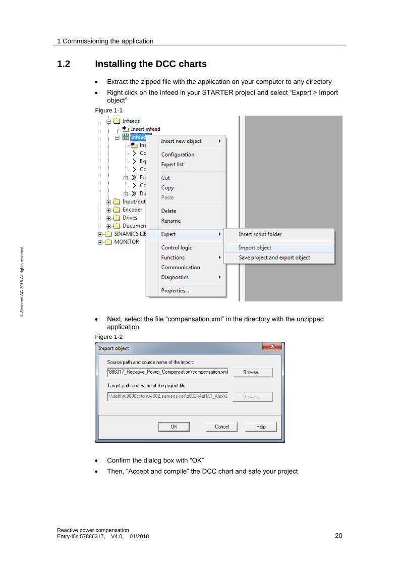
1.2 Installing the DCC charts
Extract the zipped file with the application on your computer to any directory
Right click on the infeed in your STARTER project and select “Expert > Import object”
Figure 1-1
Next, select the file “compensation.xml” in the directory with the unzipped application
Figure 1-2
Confirm the dialog box with “OK”
Then, “Accept and compile” the DCC chart and safe your project
1 Commissioning the application
Reactive power compensation Entry-ID: 57886317, V4.0, 01/2018 21
S
iem
en
s A
G 2
01
8 A
ll ri
gh
ts r
ese
rve
d
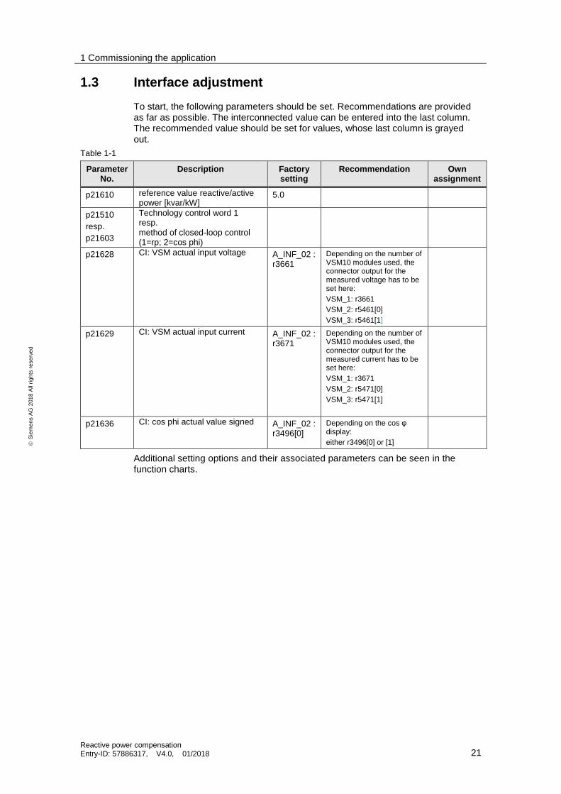
1.3 Interface adjustment
To start, the following parameters should be set. Recommendations are provided as far as possible. The interconnected value can be entered into the last column. The recommended value should be set for values, whose last column is grayed out.
Table 1-1
Parameter No.
Description Factory setting
Recommendation Own assignment
p21610 reference value reactive/active power [kvar/kW]
5.0
p21510
resp.
p21603
Technology control word 1 resp. method of closed-loop control (1=rp; 2=cos phi)
p21628 CI: VSM actual input voltage A_INF_02 : r3661
Depending on the number of VSM10 modules used, the connector output for the measured voltage has to be set here:
VSM_1: r3661
VSM_2: r5461[0]
VSM_3: r5461[1]
p21629 CI: VSM actual input current A_INF_02 : r3671
Depending on the number of VSM10 modules used, the connector output for the measured current has to be set here:
VSM_1: r3671
VSM_2: r5471[0]
VSM_3: r5471[1]
p21636 CI: cos phi actual value signed A_INF_02 : r3496[0]
Depending on the cos φ display:
either r3496[0] or [1]
Additional setting options and their associated parameters can be seen in the function charts.

1 Commissioning the application
Reactive power compensation Entry-ID: 57886317, V4.0, 01/2018 22
S
iem
en
s A
G 2
01
8 A
ll ri
gh
ts r
ese
rve
d
1.4 Information about processing time
The following sampling times are preset:
Figure 1-3
This causes the following computing load:
Table 1-2
Execution group Standard sampling time [ms]
Processing time required [%]
Own assignment
Compensation 2 7.8
Control Unit 16 0.1
By setting larger times, a considerable reduction of the computing load is possible. This must be taken into account especially if, in addition to the Active Line Module, several drives are also created on the same CU320-2. This is shown in the following example:
Table 1-3
Execution group Changed sampling time [ms]
Processing time required [%]
Compensation 16 0.9
Control Unit 32 0.1

2 Program description
Reactive power compensation Entry-ID: 57886317, V4.0, 01/2018 23
S
iem
en
s A
G 2
01
8 A
ll ri
gh
ts r
ese
rve
d
2 Program description
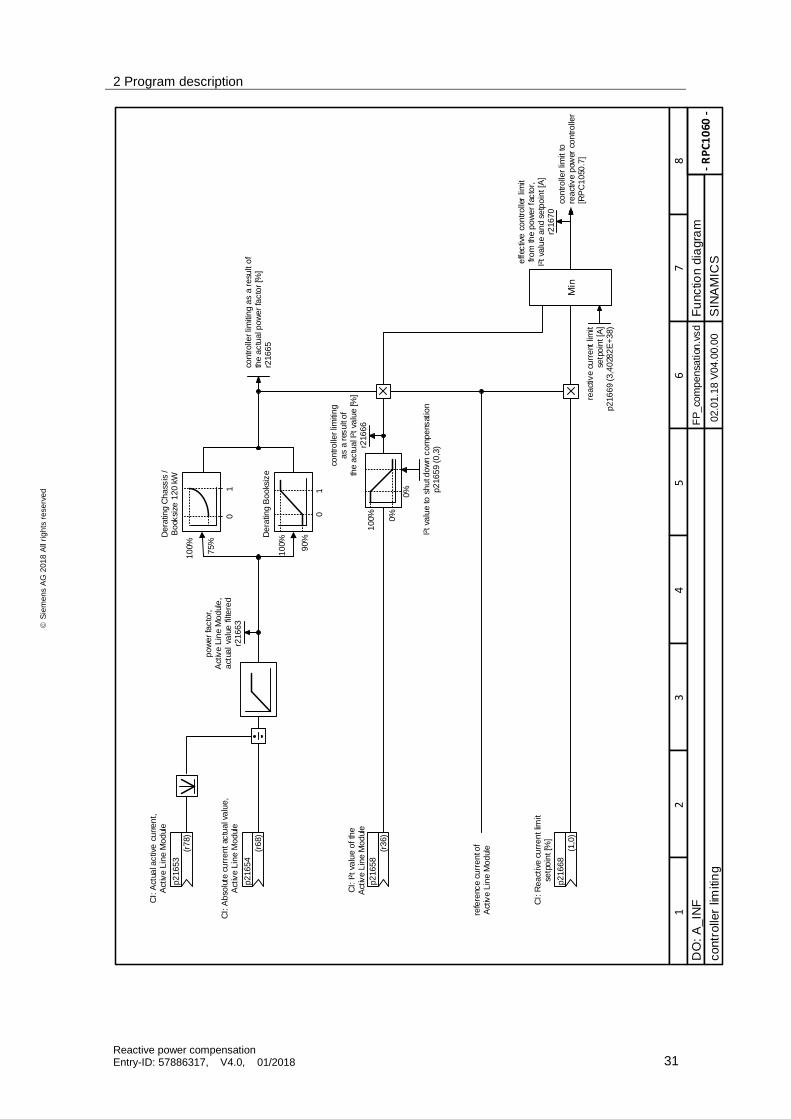
2.1 Function charts

2 Program description
Reactive power compensation Entry-ID: 57886317, V4.0, 01/2018 24
S
iem
en
s A
G 2
01
8 A
ll ri
gh
ts r
ese
rve
d
(0)
BI:
en
able
re
act
ive
curr
en
t co
ntro
l
p21
605
(0)
BO
: m
eth
od
of cl
ose
d-
loo
p co
ntrol a
ctiv
e(1
=re
act
ive
pow
er; 0=
cos
ph
i)
p21
603
(0)
BI:
en
able
dro
op
inp
utfo
r m
ast
er/
slave
op
era
tion
p21
725
1
CI: T
ech
no
logy
con
tro
l wor
d 1
(0)
p21
510
Bit
0
Bit
1
Bit
2
Bit
3
Bit
4
Bit
5
Bit
6
Bit
7
Bit
8
Bit
9
Bit
10
Bit
11
Bit
12
Bit
13
Bit
14
Bit
15
r21
520
CO
: Te
chS
TW
1 a
ctiv
e
enab
le rea
ctiv
e c
urre
nt co
ntrol [
RP
C 1
010
.4]
me
tho
d o
f cl
ose
d lo
op
con
tro
l [R
PC
1010
.1], [
RP
C 1
020
.7], [
RP
C 1
030
.7], [
RP
C 1
040
.4], [
RP
C 1
050
.4]
en
able
dro
op
[RP
C 1
050
.1]
p2
100
0[1
] =
[1
002
]C
on
tro
lUn
it
- R
PC
10
05 -
Fu
nctio
n d
iagra
m
87
65
43
21
FP
_co
mpensa
tion
.vsd
DO
: A
_IN
F
SIN
AM
ICS
02.0
1.1
8 V
04.0
0.0
0C
ontr
ol w
ord
s pa
rt 1
no
t as
sig
ned
no
t as
sig
ned
no
t as
sig
ned
no
t as
sig
ned
no
t as
sig
ned
no
t as
sig
ned
no
t as
sig
ned
no
t as
sig
ned
no
t as
sig
ned
no
t as
sig
ned
no
t as
sig
ned
no
t as
sig
ned
no
t as
sig
ned

2 Program description
Reactive power compensation Entry-ID: 57886317, V4.0, 01/2018 25
S
iem
en
s A
G 2
01
8 A
ll ri
gh
ts r
ese
rve
d
11 12 13 14 15
1 =
clo
sed lo
op
co
ntr
ol r
ele
ase
d
Tech
nolo
gy
stat
us w
ord
1
1 =
re
ac
tiv
e p
ow
er c
om
pe
ns
atio
n a
ctiv
e
1 =
re
se
rve
d
1 =
re
ac
tiv
e c
urr
ent
co
ntr
olle
r a
t u
pp
er lim
it
1 =
re
ac
tiv
e c
urr
ent
co
ntr
olle
r a
t lo
we
r lim
it
1 =
re
se
rve
d
1 =
re
se
rve
d
1 =
re
se
rve
d
1 =
re
se
rved
1 =
re
se
rve
d
1 =
re
se
rved
1 =
re
se
rve
d
1 =
re
se
rved
1 =
re
se
rve
d
1 =
re
se
rve
d
1 =
re
se
rved
9 10876543210
Bit
No
.r2
154
1
CO
: T
ech
no
logy
sta
tus
wo
rd 1
p2
100
0[1
] =
[1
002
]C
on
tro
lUn
it
- R
PC
10
07 -
Fu
nctio
n d
iagra
m
87
65
43
21
FP
_co
mpensa
tion
.vsd
DO
: A
_IN
F
SIN
AM
ICS
02.0
1.1
8 V
04.0
0.0
0S
tatu
s w
ord
s p
art
1

2 Program description
Reactive power compensation Entry-ID: 57886317, V4.0, 01/2018 26
S
iem
en
s A
G 2
01
8 A
ll ri
gh
ts r
ese
rve
d
- R
PC
10
10 -
Fu
nctio
n d
iagra
m
87
65
43
21
FP
_co
mpensa
tion
.vsd
DO
: A
_IN
F
SIN
AM
ICS
02.0
1.1
8 V
04.0
0.0
0contr
ol un
it an
d s
etp
oin
t cha
nn
el
(r8
63.0
)
BI:
Op
era
tion
fe
edb
ack
sig
nal
fro
m A
ctiv
e L
ine
Mo
dule
p2
162
3
&
1
thre
shold
abso
lute
val
ue
act
ive
po
we
r [k
W]
p2
160
6 (
1.0
)
En
able
co
ntro
l to
re
act
ive
curr
ent
co
ntro
ller
[RP
C1
050
.5]
En
able
an
d s
et
setp
oin
t gen
era
tor
[RP
C1
040
.4]
BO
: in
tern
al r
ele
ase
co
ntrol
r21
607
me
thod
of cl
ose
d lo
op c
ontro
l [R
PC
1005
.3]B
O: m
eth
od
of cl
ose
d-loo
p co
ntrol a
ctiv
e(1
=re
act
ive
pow
er; 0=
cos
ph
i)
r21
604
p2
100
0[0
] =
[16]
Co
mp
en
satio
n

2 Program description
Reactive power compensation Entry-ID: 57886317, V4.0, 01/2018 27
S
iem
en
s A
G 2
01
8 A
ll ri
gh
ts r
ese
rve
d
- R
PC
10
20 -
Fu
nctio
n d
iagra
m
87
65
43
21
FP
_co
mpensa
tion
.vsd
DO
: A
_IN
F
SIN
AM
ICS
02.0
1.1
8 V
04.0
0.0
0setp
oin
t p
repa
ration
CI: R
ea
ctiv
e p
ow
er se
tpoi
nt [%
]
(0,0
)
p2
161
1
fixed
rea
ctiv
e p
ow
er
[kvar
]p2
161
3 (
0,0
)
refe
renc
e v
alu
e re
act
ive/
act
ive
pow
er
[kvar
/kW
]p2
161
0 (
5.0
)
0≠0
CI: c
os
phi s
etp
oin
t [%
]
(0,0
)
p2
163
1
cos
ph
i fix
ed v
alu
ep2
163
3 (
1,0
)<1>
0.3
xz
-z
y
xy
-z
z
rea
ctiv
e p
ower
se
tpo
int [
kvar
]r2
161
2
sig
n d
efin
itio
nT
he
sig
n d
efini
tio
n as
ge
nera
tor co
mp
lies
with
the
use
in g
rid
sta
ndard
s (e
g V
DE
-AR
-N 4
105
) or
corr
esp
on
ds to
the g
en
erato
r re
fere
nce
arrow
sys
tem
.
A p
osi
tive
re
act
ive
pow
er s
etp
oin
t or
a n
ega
tive c
os φ
1 c
au
ses
ove
r-exc
ite
d op
era
tion a
t th
e
com
mon
grid
co
nne
ctio
n poi
nt
- th
e s
yste
m b
eha
ves
like
a c
ap
aci
tor
con
necte
d to
the m
ain
s
A n
eg
ativ
e rea
ctiv
e p
ow
er se
tpoi
nt o
r a
posi
tive
co
s φ
1 c
ause
s u
nde
r-e
xcite
d o
per
atio
n a
t th
e
com
mon
grid
co
nne
ctio
n poi
nt
- th
e s
yste
m b
eha
ves
like
an
ind
ucta
nce
con
ne
cted
to
th
e m
ain
s
<1>
01se
tpo
int g
ene
rato
rse
tpo
int in
put
[RP
C1
040
.3]
me
tho
d o
f cl
ose
d-
loo
p co
ntro
l[R
PC
1005
.3]
0≠0
refe
renc
e v
alu
e re
act
ive/
act
ive
po
we
r [k
var
/kW
][R
PC
10
30.6
]

2 Program description
Reactive power compensation Entry-ID: 57886317, V4.0, 01/2018 28
S
iem
en
s A
G 2
01
8 A
ll ri
gh
ts r
ese
rve
d
- R
PC
10
30 -
Fu
nctio
n d
iagra
m
87
65
43
21
FP
_co
mpensa
tion
.vsd
DO
: A
_IN
F
SIN
AM
ICS
02.0
1.1
8 V
04.0
0.0
0actu
al v
alu
e p
rep
ara
tion
CI: R
efe
ren
ce v
olta
ge
of
the
Act
ive
Lin
e M
odu
le(r
2701
)
p2
162
7
CI: V
SM
act
ual
in
put
vol
tage
(r3
661
)
p2
162
8
CI: V
SM
act
ual
in
put
cur
ren
t(r
36
71)
p2
162
9
CI: R
efe
ren
ce c
urre
nt o
f th
e A
ctiv
e L
ine M
odu
le(r
2702
)
p2
163
0
u(t
)
U
eff
i(t)
I e
ff
3S
eff
CI: c
os
phi a
ctu
al v
alu
e s
ign
ed
(r3
496
[0])
p2
163
6
1cos
(
)2
r21
619
CO
: a
ctiv
e p
ow
er a
ctua
la
bso
lute
val
ue
(fil
tere
d)
[%]
r21
617
CO
: A
ctua
l rea
ctiv
e
po
we
r (filt
ere
d)
[%]
01co
ntrolle
r va
lue
[RP
C1
050
.1]
setp
oin
t g
ene
rato
rse
ttin
g v
alu
e[R
PC
10
40.5
]
me
tho
d o
f cl
ose
d-
loo
p co
ntro
l[R
PC
1005
.3]
act
ual re
act
ive
po
we
r (filt
ered
) [k
var
]
r21
616
act
ive
po
we
r a
ctua
la
bso
lute
val
ue
(fil
tere
d) [k
W]
r21
618
-1
Sign
+ o
r -

2 Program description
Reactive power compensation Entry-ID: 57886317, V4.0, 01/2018 29
S
iem
en
s A
G 2
01
8 A
ll ri
gh
ts r
ese
rve
d
- R
PC
10
40 -
Fu
nctio
n d
iagra
m
87
65
43
21
FP
_co
mpensa
tion
.vsd
DO
: A
_IN
F
SIN
AM
ICS
02.0
1.1
8 V
04.0
0.0
0setp
oin
t g
en
era
tor
SET
SET_
VA
L
tyx
ram
p u
p/d
ow
n tim
e [m
s]
(no
rma
lize
d to
ac
tua
l co
ntr
ol)
p2
164
0 (
10
000
ms)
EN
01
me
tho
d o
f cl
ose
d-
loo
p co
ntrol
[RP
C1
005
.3]
CI: R
efe
ren
ce p
ow
er
Act
ive
Lin
e M
odul
e [
kW]
(r2
704
)
p2
164
3
-1
inp
ut s
etp
oin
t g
ene
rato
rfrom
se
tpoin
t pr
ep
ara
tion
[RP
C1
020
.8]
con
tro
ller se
toin
t to
rea
ctiv
e c
ont
rolle
r[R
PC
10
50.1
]
enab
le/S
et s
etp
oin
t g
en
erato
rfro
m c
on
tro
ller e
nab
le[R
PC
1010
.8]
settin
g v
alu
e s
etp
oin
t g
ene
rato
rfrom
act
ual v
alue
pre
pa
ration
[RP
C1
030
.8]

2 Program description
Reactive power compensation Entry-ID: 57886317, V4.0, 01/2018 30
S
iem
en
s A
G 2
01
8 A
ll ri
gh
ts r
ese
rve
d
- R
PC
10
50 -
Fu
nctio
n d
iagra
m
87
65
43
21
FP
_co
mpensa
tion
.vsd
DO
: A
_IN
F
SIN
AM
ICS
02.0
1.1
8 V
04.0
0.0
0re
active
curr
ent
contr
ol
Poin
t w
here
ada
ptio
n st
arts, lo
wer
[%]
p21679 (
0)
Poin
t w
here
adapt
ion
starts,
uppe
r [%
]p21681
(0)
Adapt
ion
fact
or, u
ppe
rp21682 (
1)
Adap
tion
fact
or, lo
wer
p216
80 (
1)
CI: P
gain
, a
dap
tatio
n si
gn
al,
react
ive
curr
ent
controlle
r(0
)
p21678
Kp
Tn
Y
Yin
teg
ral t
ime
EN
ICIS
IH
inte
gra
l tim
e,
react
ive
curr
ent
co
ntrolle
r [m
s]
p21803 (
1000)
controlle
r enabl
e fro
m
control u
nit
[RP
C1010
.8]
r2170
1C
O: R
eact
ive c
urr
ent
setp
oin
t to
Ac
tive
Lin
e M
od
ule
Dro
op fa
cto
r, r
eact
ive
curr
ent
controlle
rp216
83 (
0,0
2)
(0)
BI:
Enab
le d
roop in
put
fo
r m
ast
er/
slave
opera
tion
p21725
setp
oin
t re
activ
e p
ow
er
controlle
rfrom
ste
poin
t ge
nera
tor
[RP
C1020
.8]
Act
ual v
alu
e r
eact
ive p
ow
er cont
rolle
rfrom
act
ual v
alue p
repara
tion
[RP
C1030
.8]
01
0
act
ual se
tpoin
t fr
om
the d
roop in
put
r21
684
–+ –
-1
refe
renc
e c
urr
en
t of
Act
ive L
ine
Modul
eBO
: R
eact
ive c
urr
ent co
ntro
ller
at up
per lim
it
r2177
3
BO
: R
eact
ive c
urr
ent
cont
rolle
r at lo
wer
lim
it
r2177
4
react
ive
curr
ent
co
ntr
olle
r lim
it fr
om
co
ntrolle
r lim
its
[RP
C1060
.8]
01
meth
od
of cl
ose
d-
loop
control
[RP
C1005
.3]
Pro
portio
nal a
ctio
n c
oeffi
cie
nt,
react
ive
pow
er c
ontrol [A
/kvar
] p2
1800 (
1,3
)
Pro
portio
nal a
ctio
n c
oeffi
cie
nt,
cos
phi c
ontr
ol [
A]
p218
01 (
1,3
)
2 Program description
Reactive power compensation Entry-ID: 57886317, V4.0, 01/2018 31
S
iem
en
s A
G 2
01
8 A
ll ri
gh
ts r
ese
rve
d
- R
PC
10
60 -
Fu
nctio
n d
iagra
m
87
65
43
21
FP
_co
mpensa
tion
.vsd
DO
: A
_IN
F
SIN
AM
ICS
02.0
1.1
8 V
04.0
0.0
0contr
olle
r lim
itin
g
CI: A
ctua
l activ
e c
urre
nt,
Act
ive
Lin
e M
od
ule
(r7
8)
p21653
CI: A
bso
lute
cu
rre
nt ac
tua
l va
lue,
Act
ive
Lin
e M
od
ule
(r6
8)
p21654
po
we
r fa
cto
r,
Act
ive
Lin
e M
od
ule
, a
ctua
l va
lue
filt
ere
dr2
1663
CI: I
²t v
alu
e o
f th
e
Act
ive
Lin
e M
od
ule
(r3
6)
p21658
controlle
r lim
iting
a
s a
resu
lt o
f th
e a
ctu
al I
²t v
alu
e [%
]r2
1666
Min
10
0%
0%
0%
I²t va
lue
to s
hu
t do
wn
co
mp
ens
atio
np21659 (
0,3
)
CI: R
ea
ctiv
e c
urr
en
t lim
it se
tpo
int [%
]
(1,0
)
p21668
rea
ctiv
e cu
rrent
lim
it
setp
oin
t [A
]p216
69 (
3,4
028
2E
+38)
effec
tive
co
ntrolle
r lim
it from
th
e p
ow
er fa
cto
r,I²
t va
lue
an
d se
tpo
int [A
]r2
1670
controlle
r lim
it to
re
act
ive
pow
er c
ontrolle
r [R
PC
10
50.7
]
controlle
r lim
iting
as a
resu
lt o
f th
e a
ctu
al p
ow
er fa
cto
r [%
]r2
1665
01
90%
100%
10
0%
75%
01
De
ratin
g C
hass
is /
Bo
oksi
ze 1
20
kW
De
ratin
g B
oo
ksiz
e
refe
renc
e c
urr
en
t of
Act
ive
Lin
e M
od
ule
2 Program description
Reactive power compensation Entry-ID: 57886317, V4.0, 01/2018 32
S
iem
en
s A
G 2
01
8 A
ll ri
gh
ts r
ese
rve
d
2.2 Parameter list
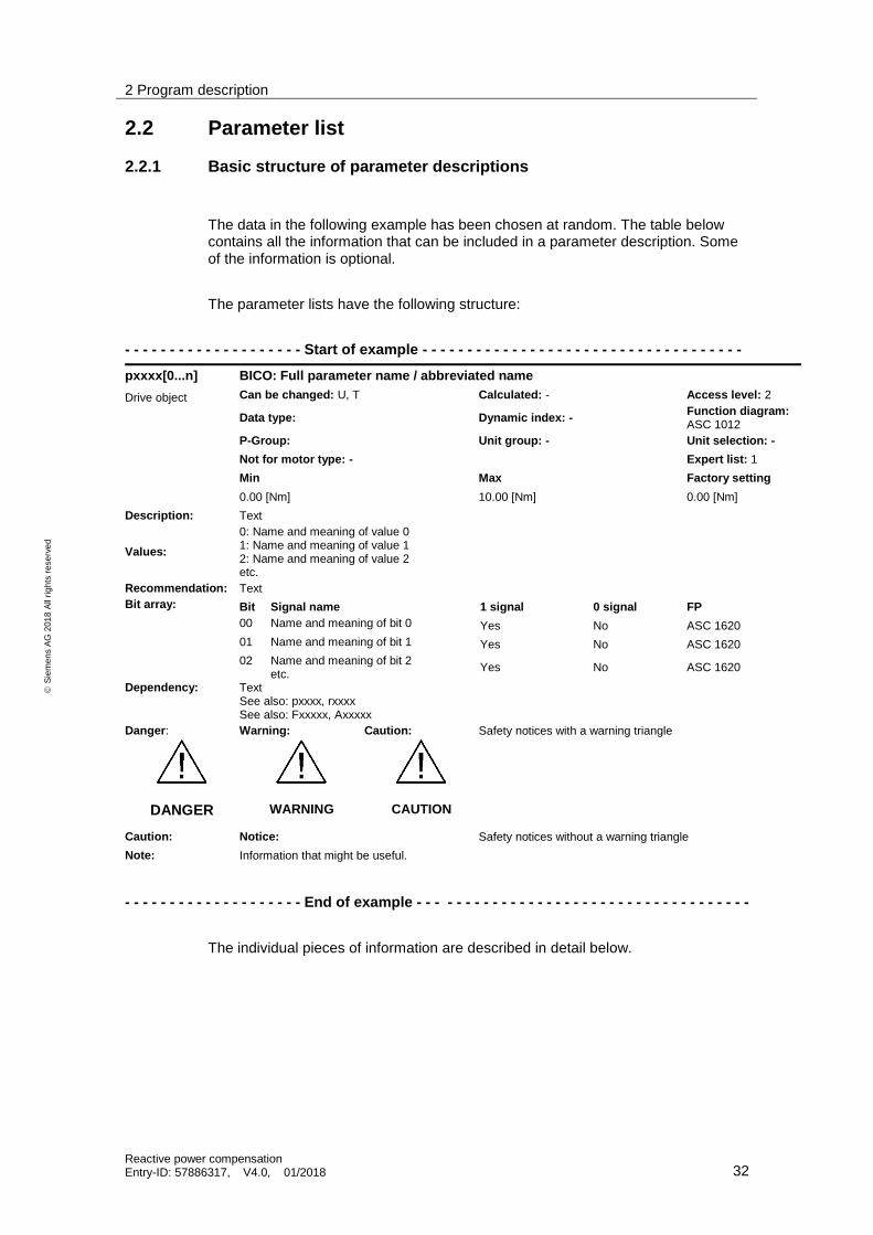
2.2.1 Basic structure of parameter descriptions
The data in the following example has been chosen at random. The table below contains all the information that can be included in a parameter description. Some of the information is optional.
The parameter lists have the following structure:
- - - - - - - - - - - - - - - - - - - - Start of example - - - - - - - - - - - - - - - - - - - - - - - - - - - - - - - - - - - -
pxxxx[0...n] BICO: Full parameter name / abbreviated name
Drive object Can be changed: U, T Calculated: - Access level: 2
Data type: Dynamic index: - Function diagram: ASC 1012
P-Group: Unit group: - Unit selection: -
Not for motor type: - Expert list: 1
Min Max Factory setting
0.00 [Nm] 10.00 [Nm] 0.00 [Nm]
Description: Text
Values:
0: Name and meaning of value 0 1: Name and meaning of value 1 2: Name and meaning of value 2 etc.
Recommendation: Text
Bit array: Bit Signal name 1 signal 0 signal FP
00 Name and meaning of bit 0 Yes No ASC 1620
01 Name and meaning of bit 1 Yes No ASC 1620
02 Name and meaning of bit 2 etc.
Yes No ASC 1620
Dependency: Text See also: pxxxx, rxxxx See also: Fxxxxx, Axxxxx
Danger: Warning: Caution: Safety notices with a warning triangle
DANGER
WARNING
CAUTION
Caution: Notice: Safety notices without a warning triangle
Note: Information that might be useful.
- - - - - - - - - - - - - - - - - - - - End of example - - - - - - - - - - - - - - - - - - - - - - - - - - - - - - - - - - - - -
The individual pieces of information are described in detail below.

2 Program description
Reactive power compensation Entry-ID: 57886317, V4.0, 01/2018 33
S
iem
en
s A
G 2
01
8 A
ll ri
gh
ts r
ese
rve
d
pxxxx[0...n] Parameter number
The parameter number is made up of a "p" or "r", followed by the parameter number and the index or bit field (optional).
Examples of the representation in the parameter list:
p... adjustable parameters (can be read and written)
r... display parameters (read only)
p0918 Adjustable parameter 918
p0099[0...3] Adjustable parameter 99 indices 0 to 3
p1001[0...n] Adjustable parameter 1001 indices 0 to n
(n = configurable)
r0944 Display parameter 944
r2129.0...15 Display parameter 2129 with bit array from
Bit 0 (lowest bit) to bit 15 (highest bit)
Other examples for the notation in the documentation:
p1070[1] Adjustable parameter 1070, index 1
p2098[1].3 Adjustable parameter 2098, index 1 bit 3
r0945[2](3) Display parameter 945, index 2 of
Drive object 3
p0795.4 Adjustable parameter 795, bit 4
The following applies to adjustable parameters:
The parameter value "when shipped from the factory" is specified under "Factory setting" with the relevant unit in square parentheses. The value can be adjusted within the range defined by "Min" and "Max".
The term "linked parameterization" is used in cases where changes to adjustable parameters affect the settings of other parameters.
Linked parameterization can occur, for example, as a result of the following actions and parameters:
Executing macros
p0015, p0700, p1000, p1500
Setting the PROFIBUS telegram (BICO interconnection)
p0922
Setting component lists
p0230, p0300, p0301, p0400
Automatically calculating and preassigning
p0112, p0340, p0578, p3900
Restoring factory settings
p0970
The following applies to display parameters:
The fields "Min", "Max" and "Factory setting" are specified with a dash "-" and the relevant unit in square brackets.
2 Program description
Reactive power compensation Entry-ID: 57886317, V4.0, 01/2018 34
S
iem
en
s A
G 2
01
8 A
ll ri
gh
ts r
ese
rve
d
Note The parameter list can contain parameters that are not visible in the expert lists of the respective commissioning software (e.g. parameters for trace functions).
The parameters of the application example are completely visible in the expert list.
BICO: Full parameter name / abbreviated name
The following abbreviations can appear in front of the BICO parameter name:
BI: Binector Input Binector input)
This parameter selects the source of a digital signal.
BO: Binector output Binector output)
This parameter is available as an digital signal for interconnection with other parameters.
CI: Connector Input Connector input)
This parameter selects the source of an "analog" signal.
CO: Connector output Connector output)
This parameter is available as an "analog" signal for interconnection with other parameters.
CO/BO: Connector/Binector Output Connector/Binector Output)
This parameter is available as both an "analog" and also as digital signals for interconnection with other parameters.
Note A BICO input (BI/CI) cannot be just interconnected with any BICO output (BO/CO, signal source).
When interconnecting a BICO input using the commissioning software, only the signal sources that are actually possible are listed.
Function diagrams 1020 ... 1030 of the List Manual explain the symbols for BICO parameters and how to handle BICO technology.

2 Program description
Reactive power compensation Entry-ID: 57886317, V4.0, 01/2018 35
S
iem
en
s A
G 2
01
8 A
ll ri
gh
ts r
ese
rve
d
Drive object (function module)
A drive object (DO) is an independent, "self-contained" functional unit that has its own parameters and, in some cases, faults and alarms.
When carrying out commissioning using the commissioning software, you can select/deselect additional functions and their parameters by activating/deactivating function modules accordingly.
Note References: /FH1/ SINAMICS S120 Function Manual Drive Functions
The parameter list specifies the associated drive object and function module for each individual parameter.
Examples:
p1070 CI: Main setpoint
SERVO (extended setpoint), VECTOR
The parameter is available only in association with drive object SERVO and the "Extended setpoint channel" Function Module or with drive object VECTOR irrespective of activated Function Modules.
p1055 BI: Jogging bit 0
SERVO, VECTOR
For drive objects SERVO and VECTOR, regardless of which function modules have been activated, this parameter is always available. This means that it is available with every activated function module belonging to the drive object.
A parameter can belong to one, several, or all drive objects.
Note All parameters of this application example are also available after installation at the SERVO and VECTOR drive objects. The "Position controller" function module is required for the functionality.

2 Program description
Reactive power compensation Entry-ID: 57886317, V4.0, 01/2018 36
S
iem
en
s A
G 2
01
8 A
ll ri
gh
ts r
ese
rve
d
Can be changed
The "-" sign indicates that the parameter can be changed in any object state and that the change will be effective immediately.
The information "C1(x), C2(x), T, U" ((x): optional) means that the parameter can be changed only in the specified drive unit state and that the change will not take effect until the unit switches to another state. One or more states are possible.
The following states are available for the parameter:
C1(x) Device commissioning C1: Commissioning 1
Device is in the process of being commissioned (p0009 > 0).
Pulses cannot be enabled.
The parameter can only be changed in the following device commissioning settings (p0009 > 0):
• C1: Can be changed for all settings p0009 > 0.
• C1(x): Can only be changed for settings p0009 = x
A modified parameter value does not take effect until the device commissioning mode is exited with p0009 = 0.
C2(x) Drive object commissioning C2: Commissioning 2
The drive is in the process of being commissioned (p0009 = 0 and p0010 > 0).
Pulses cannot be enabled.
The parameter can only be changed in the following drive commissioning settings (p0010 > 0):
• C2: Can be changed for all settings p0010 > 0.
• C2(x): Can only be changed for settings p0010 = x.
A modified parameter value does not take effect until the device commissioning mode is exited with p0010 = 0.
U Operation U: Run
Pulses are enabled.
T Ready to operate T: Ready to run
The pulses are not enabled and the state "C1(x)" or "C2(x)" is not active.
Note Parameter p0009 is CU-specific (available on the Control Unit).
Parameter p0010 is drive-specific (available for each drive object).
The operating state of individual drive objects is displayed in r0002.
Calculated
Specifies whether the parameter is influenced by automatic calculations. The calculation attribute defines which activities influence the parameter.

2 Program description
Reactive power compensation Entry-ID: 57886317, V4.0, 01/2018 37
S
iem
en
s A
G 2
01
8 A
ll ri
gh
ts r
ese
rve
d
Note This attribute is not relevant for the application parameters.
Access level
Specifies the minimum access level required to be able to display and change the relevant parameter. The required access level can be set using p0003.
The system uses the following access levels:
1: Standard
2: Extended
3: Expert
4: Service
Note Parameter p0003 is CU-specific (available on the Control Unit). A higher access level will also include the functions of the lower levels.
Data type
Note The data type attribute is not listed for the application parameters.
Dynamic index
Note This dynamic index attribute is not relevant for the application parameters.
Function diagram
The parameter is included in this function diagram. The structure of the parameter function and its relationship with other parameters is shown in the specified function diagram.
P-Group (refers only to access via BOP (Basic Operator Panel))
Specifies the functional group to which this parameter belongs. The required parameter group can be set via p0004.
Note Parameter p0004 is CU-specific (is available on the Control Unit).

2 Program description
Reactive power compensation Entry-ID: 57886317, V4.0, 01/2018 38
S
iem
en
s A
G 2
01
8 A
ll ri
gh
ts r
ese
rve
d
Unit, unit group and unit selection
Note These attributes are not relevant for the parameters of the application example; it is not possible to switch over the units.
Parameter values
Min Minimum value of the parameter [unit]
Max Maximum value of the parameter [unit]
Factory setting Value when shipped [unit]
In the case of a binector/connector input, the signal source of the default BICO interconnection is specified. A non-indexed connector output is assigned the index [0].
Not for motor type
Note The motor type attribute is not relevant for the application parameters.
Scaling
Note The scaling attribute is not relevant for the application parameters. If there is a reference to another parameter, then this is indicated in the parameter list.
Expert list
Specifies whether this parameter is available in the expert list of the specified drive objects in the commissioning software.
1: Parameter is available in the expert list.
0: Parameter does not exist in the expert list.
Note The application does not have any parameters that do not exist in the expert list.
The support for the parameters and functions of the application example is realized via the Fehler! Verweisquelle konnte nicht gefunden werden. specified in this document.
Description
Explanation of the function of a parameter.

2 Program description
Reactive power compensation Entry-ID: 57886317, V4.0, 01/2018 39
S
iem
en
s A
G 2
01
8 A
ll ri
gh
ts r
ese
rve
d
Values
Lists of the possible values of a parameter.
Recommendation
Information about recommended settings.
Index
Note The index attribute is not relevant for the application parameters.

2 Program description
Reactive power compensation Entry-ID: 57886317, V4.0, 01/2018 40
S
iem
en
s A
G 2
01
8 A
ll ri
gh
ts r
ese
rve
d
Bit array
For parameters with bit arrays, the following information is provided about each bit:
Bit number and signal name
Meaning for signal states 1 and 0
Function diagram (optional)
The signal is shown in this function diagram.
Dependency
Conditions that must be fulfilled in conjunction with this parameter. Also includes special effects that can occur between this parameter and others.
Where necessary, "Refer to:" indicates the following information:
List of other relevant parameters to be considered.
List of faults and alarms to be considered.
Safety notices
Important information that must be observed to avoid the risk of physical injury or material damage.
Information that must be observed to avoid any problems. Information that the user may find useful.
Number ranges of parameters
The parameters of the application example are in the number range for Drive Control Chart (DCC) from 21000 to 25999.
2 Program description
Reactive power compensation Entry-ID: 57886317, V4.0, 01/2018 41
S
iem
en
s A
G 2
01
8 A
ll ri
gh
ts r
ese
rve
d
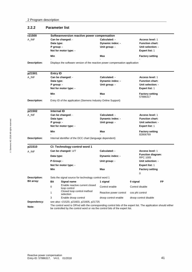
2.2.2 Parameter list
r21500 Softwareversion reactive power compensation
A_INF Can be changed: - Calculated: - Access level: 1
Data type: Dynamic index: - Function chart:
P group: - Unit group: - Unit selection: -
Not for motor type: - Expert list: 1
Min Max Factory setting - - -
Description: Displays the software version of the reactive power compensation application
p21501 Entry ID
A_INF Can be changed: - Calculated: - Access level: 1
Data type: Dynamic index: - Function chart:
P group: - Unit group: - Unit selection: -
Not for motor type: - Expert list: 1
Min Max Factory setting - - 57886317
Description: Entry ID of the application (Siemens Industry Online Support)
p21502 Internal ID
A_INF Can be changed: - Calculated: - Access level: 1
Data type: Dynamic index: - Function chart:
P group: - Unit group: - Unit selection: -
Not for motor type: - Expert list: 1
Min Max Factory setting - - 82806769
Description: Internal identifier of the DCC chart (language dependent)
p21510 CI: Technology control word 1
A_INF Can be changed: U/T Calculated: - Access level: 1
Data type: Dynamic index: - Function diagram: RPC 1005
P-Group: - Unit group: - Unit selection: -
Not for motor type: - Expert list: 1
Min Max Factory setting
0
Description: Sets the signal source for technology control word 1
Bit array: Bit Signal name 1 signal 0 signal FP
0 Enable reactive current closed loop control
Control enable Control disable
1 Closed loop control method selection
Reactive power control cos phi control
3 Enable droop control droop control enable droop control disable
Dependency: see also: r21520, p21603, p21605, p21725
Note: The control word is OR'ed with the corresponding control bits of the expert list. The application should either be controlled by the control word or via the control bits of the expert list.
2 Program description
Reactive power compensation Entry-ID: 57886317, V4.0, 01/2018 42
S
iem
en
s A
G 2
01
8 A
ll ri
gh
ts r
ese
rve
d
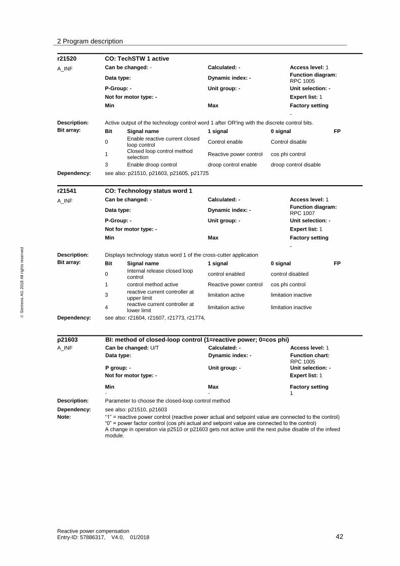
r21520 CO: TechSTW 1 active
A_INF Can be changed: - Calculated: - Access level: 1
Data type: Dynamic index: - Function diagram: RPC 1005
P-Group: - Unit group: - Unit selection: -
Not for motor type: - Expert list: 1
Min Max Factory setting
-
Description: Active output of the technology control word 1 after OR'ing with the discrete control bits.
Bit array: Bit Signal name 1 signal 0 signal FP
0 Enable reactive current closed loop control
Control enable Control disable
1 Closed loop control method selection
Reactive power control cos phi control
3 Enable droop control droop control enable droop control disable
Dependency: see also: p21510, p21603, p21605, p21725
r21541 CO: Technology status word 1
A_INF Can be changed: - Calculated: - Access level: 1
Data type: Dynamic index: - Function diagram: RPC 1007
P-Group: - Unit group: - Unit selection: -
Not for motor type: - Expert list: 1
Min Max Factory setting
-
Description: Displays technology status word 1 of the cross-cutter application
Bit array: Bit Signal name 1 signal 0 signal FP
0 Internal release closed loop control
control enabled control disabled
1 control method active Reactive power control cos phi control
3 reactive current controller at upper limit
limitation active limitation inactive
4 reactive current controller at lower limit
limitation active limitation inactive
Dependency: see also: r21604, r21607, r21773, r21774,
p21603 BI: method of closed-loop control (1=reactive power; 0=cos phi)
A_INF Can be changed: U/T Calculated: - Access level: 1
Data type: Dynamic index: - Function chart: RPC 1005
P group: - Unit group: - Unit selection: -
Not for motor type: - Expert list: 1
Min Max Factory setting - - 1
Description: Parameter to choose the closed-loop control method
Dependency: see also: p21510, p21603
Note: “1” = reactive power control (reactive power actual and setpoint value are connected to the control) “0” = power factor control (cos phi actual and setpoint value are connected to the control) A change in operation via p2510 or p21603 gets not active until the next pulse disable of the infeed module.

2 Program description
Reactive power compensation Entry-ID: 57886317, V4.0, 01/2018 43
S
iem
en
s A
G 2
01
8 A
ll ri
gh
ts r
ese
rve
d
r21604 BO: method of closed-loop control active (1=reactive power; 0=cos phi)
A_INF Can be changed: - Calculated: - Access level: 1
Data type: Dynamic index: - Function chart: RPC 1010
P group: - Unit group: - Unit selection: -
Not for motor type: - Expert list: 1
Min Max Factory setting - - 1
Description: Parameter to choose the closed-loop control method
Dependency: see also: p21510, p21603
Note: “1” = reactive power control (reactive power actual and setpoint value are connected to the control) “0” = power factor control (cos phi actual and setpoint value are connected to the control) A change in operation via p2510 or p21603 gets not active until the next pulse disable of the infeed module.
p21605 BI: Enable reactive current control
A_INF Can be changed: U/T Calculated: - Access level: 1
Data type: Dynamic index: - Function chart: RPC 1005
P group: - Unit group: - Unit selection: -
Not for motor type: - Expert list: 1
Min Max Factory setting - - 1
Description: Sets the signal source to enable reactive power compensation
Dependency: see also: p21510
Note: If the reactive power compensation should operate permanently, then it can be permanently enabled using a fixed binector "1".
p21606 threshold absolute value active power [kW]
A_INF Can be changed: U/T Calculated: - Access level: 1
Data type: Dynamic index: - Function chart: RPC 1010
P group: - Unit group: - Unit selection: -
Not for motor type: - Expert list: 1
Min Max Factory setting 0 3.40282E+43 1.0
Description: Parameter to set threshold for the absolute value of the active power, which disables the closed-loop control, if its value is not reached.
Note: In this parameter is set the minimum value of active power that must be reached to enable the closed-loop control.
r21607 BO: internal release control
A_INF Can be changed: - Calculated: - Access level: 1
Data type: Dynamic index: - Function chart: RPC 1010
P group: - Unit group: - Unit selection: -
Not for motor type: - Expert list: 1
Min Max Factory setting - - -1.0
Description: Feedback for the internal release of the closed loop reactive current control
Dependency: see also: p21603, p21606
Note: The control is dependent from the operation mode of the Active Line Module and in case of cos phi control from reaching the threshold set for active power.
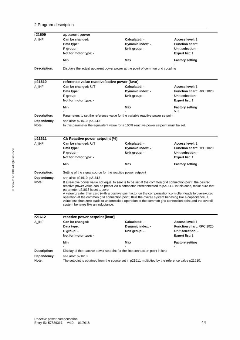
2 Program description
Reactive power compensation Entry-ID: 57886317, V4.0, 01/2018 44
S
iem
en
s A
G 2
01
8 A
ll ri
gh
ts r
ese
rve
d
r21609 apparent power
A_INF Can be changed: Calculated: - Access level: 1
Data type: Dynamic index: - Function chart:
P group: - Unit group: - Unit selection: -
Not for motor type: - Expert list: 1
Min Max Factory setting - - -
Description: Displays the actual apparent power power at the point of common grid coupling
p21610 reference value reactive/active power [kvar]
A_INF Can be changed: U/T Calculated: - Access level: 1
Data type: Dynamic index: - Function chart: RPC 1020
P group: - Unit group: - Unit selection: -
Not for motor type: - Expert list: 1
Min Max Factory setting - - 5.0
Description: Parameters to set the reference value for the variable reactive power setpoint
Dependency: see also: p21610, p21613
Note: In this parameter the equivalent value for a 100% reactive power setpoint must be set.
p21611 CI: Reactive power setpoint [%]
A_INF Can be changed: U/T Calculated: - Access level: 1
Data type: Dynamic index: - Function chart: RPC 1020
P group: - Unit group: - Unit selection: -
Not for motor type: - Expert list: 1
Min Max Factory setting - - -
Description: Setting of the signal source for the reactive power setpoint
Dependency: see also: p21610, p21613
Note: If a reactive power value not equal to zero is to be set at the common grid connection point, the desired reactive power value can be preset via a connector interconnected to p21611. In this case, make sure that parameter p21613 is set to zero. A value greater than zero (with a positive gain factor on the compensation controller) leads to overexcited operation at the common grid connection point, thus the overall system behaving like a capacitance, a value less than zero leads to underexcited operation at the common grid connection point and the overall system behaves like an inductance.
r21612 reactive power setpoint [kvar]
A_INF Can be changed: Calculated: - Access level: 1
Data type: Dynamic index: - Function chart: RPC 1020
P group: - Unit group: - Unit selection: -
Not for motor type: - Expert list: 1
Min Max Factory setting - - -
Description: Display of the reactive power setpoint for the line connection point in kvar
Dependency: see also: p21613
Note: The setpoint is obtained from the source set in p21611 multiplied by the reference value p21610.

2 Program description
Reactive power compensation Entry-ID: 57886317, V4.0, 01/2018 45
S
iem
en
s A
G 2
01
8 A
ll ri
gh
ts r
ese
rve
d
p21613 fixed reactive power [kvar]
A_INF Can be changed: U/T Calculated: - Access level: 1
Data type: Dynamic index: - Function chart: RPC 1020
P group: - Unit group: - Unit selection: -
Not for motor type: - Expert list: 1
Min Max Factory setting - - 0.0
Description: Parameters to set an absolute value for reactive power setpoint in kvar
Note: The value of this parameter is used as setpoint for the closed-loop control, if it is not equal to zero. Otherwise the input interconnected to p21611 is used as the setpoint for the closed-loop control. So this parameter has to be set to zero, if the input interconnected to p21611 should be used as setpoint for the closed-loop control. If you want to use the value from p21613 as setpoint for the closed-loop control and want to set the value to zero, you have to pay attention that the value connected to p21611 is also zero. A value greater than zero (with a positive gain factor on the compensation controller) leads to overexcited operation at the common grid connection point, thus the overall system behaving like a capacitance, a value less than zero leads to underexcited operation at the common grid connection point and the overall system behaves like an inductance.
r21616 actual reactive power (filtered) [kvar]
A_INF Can be changed: Calculated: - Access level: 1
Data type: Dynamic index: - Function chart: RPC 1030
P group: - Unit group: - Unit selection: -
Not for motor type: - Expert list: 1
Min Max Factory setting - - -
Description: Displays the actual reactive power in kvar
Note: The value is obtained from VSM10’s measurement. It is averaged over 10 cycles.
r21617 CO: Actual reactive power (filtered) [%]
A_INF Can be changed: Calculated: - Access level: 1
Data type: Dynamic index: - Function chart: RPC 1030
P group: - Unit group: - Unit selection: -
Not for motor type: - Expert list: 1
Min Max Factory setting - - -
Description: Displays the normalized actual reactive power value
Dependency: see also p21610
Note: The value shows the actual reactive power value, based on to the set normalization value. This value can be connected to the communication for example.
r21618 active power actual absolute value (filtered) [kW]
A_INF Can be changed: Calculated: - Access level: 1
Data type: Dynamic index: - Function chart: RPC 1030
P group: - Unit group: - Unit selection: -
Not for motor type: - Expert list: 1
Min Max Factory setting - - -
Description: Displays the actual active power in kW
Note: The value is obtained from VSM10’s measurement. It is averaged over 10 cycles.

2 Program description
Reactive power compensation Entry-ID: 57886317, V4.0, 01/2018 46
S
iem
en
s A
G 2
01
8 A
ll ri
gh
ts r
ese
rve
d
p21619 CO: active power actual absolute value (filtered) [%]
A_INF Can be changed: Calculated: - Access level: 1
Data type: Dynamic index: - Function chart: RPC 1030
P group: - Unit group: - Unit selection: -
Not for motor type: - Expert list: 1
Min Max Factory setting - - -
Description: Displays the normalized actual active power value
Dependency: see also p21510
Note: The value shows the actual active power value, based on to the set normalization value. This value can be connected to the communication for example.
p21627 CI: Reference voltage of the Active Line Module (r2701)
A_INF Can be changed: T Calculated: - Access level: 1
Data type: Dynamic index: - Function chart: RPC 1030
P group: - Unit group: - Unit selection: -
Not for motor type: - Expert list: 1
Min Max Factory setting - - r2701
Description: Sets the signal source for the reference voltage of the Active Line Module.
Note: Here r2701 of the Active Line Module has to be set.
p21628 CI: VSM actual input voltage
A_INF Can be changed: T Calculated: - Access level: 1
Data type: Dynamic index: - Function chart: RPC 1030
P group: - Unit group: - Unit selection: -
Not for motor type: - Expert list: 1
Min Max Factory setting - - r3661
Description: Sets the signal source for the actual voltage, measured by the VSM at the point of common connection (PCC).
Note: Depending on the number on VSMs used, here the connector output of the measured voltage has to be set: VSM_1: r3661; VSM_2: r 5461[0]; VSM_3: r5461[1]
p21629 CI: VSM actual input current
A_INF Can be changed: T Calculated: - Access level: 1
Data type: Dynamic index: - Function chart: RPC 1030
P group: - Unit group: - Unit selection: -
Not for motor type: - Expert list: 1
Min Max Factory setting - - r3671
Description: Sets the signal source for the actual current, measured by the VSM at the point of common connection (PCC).
Note: Depending on the number on VSMs used, here the connector output of the measured curent has to be set: VSM_1: r3671; VSM_2: r 5471[0]; VSM_3: r5471[1]
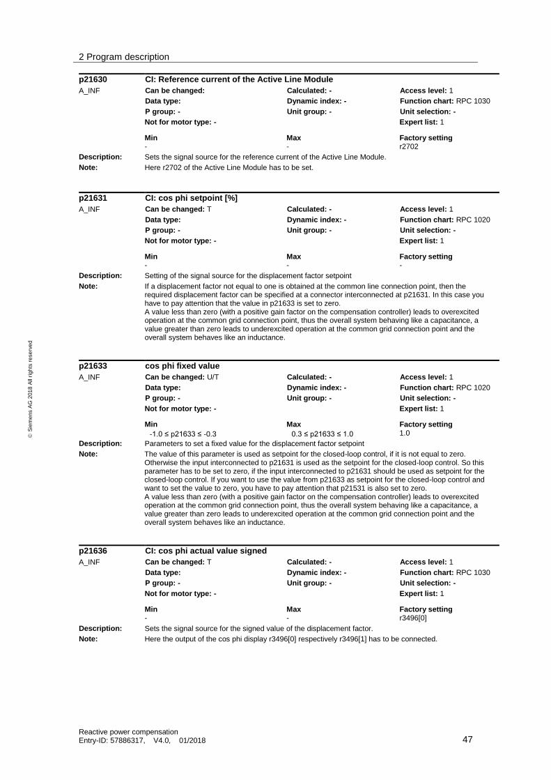
2 Program description
Reactive power compensation Entry-ID: 57886317, V4.0, 01/2018 47
S
iem
en
s A
G 2
01
8 A
ll ri
gh
ts r
ese
rve
d
p21630 CI: Reference current of the Active Line Module
A_INF Can be changed: Calculated: - Access level: 1
Data type: Dynamic index: - Function chart: RPC 1030
P group: - Unit group: - Unit selection: -
Not for motor type: - Expert list: 1
Min Max Factory setting - - r2702
Description: Sets the signal source for the reference current of the Active Line Module.
Note: Here r2702 of the Active Line Module has to be set.
p21631 CI: cos phi setpoint [%]
A_INF Can be changed: T Calculated: - Access level: 1
Data type: Dynamic index: - Function chart: RPC 1020
P group: - Unit group: - Unit selection: -
Not for motor type: - Expert list: 1
Min Max Factory setting - - -
Description: Setting of the signal source for the displacement factor setpoint
Note: If a displacement factor not equal to one is obtained at the common line connection point, then the required displacement factor can be specified at a connector interconnected at p21631. In this case you have to pay attention that the value in p21633 is set to zero. A value less than zero (with a positive gain factor on the compensation controller) leads to overexcited operation at the common grid connection point, thus the overall system behaving like a capacitance, a value greater than zero leads to underexcited operation at the common grid connection point and the overall system behaves like an inductance.
p21633 cos phi fixed value
A_INF Can be changed: U/T Calculated: - Access level: 1
Data type: Dynamic index: - Function chart: RPC 1020
P group: - Unit group: - Unit selection: -
Not for motor type: - Expert list: 1
Min Max Factory setting -1.0 ≤ p21633 ≤ -0.3 0.3 ≤ p21633 ≤ 1.0 1.0
Description: Parameters to set a fixed value for the displacement factor setpoint
Note: The value of this parameter is used as setpoint for the closed-loop control, if it is not equal to zero. Otherwise the input interconnected to p21631 is used as the setpoint for the closed-loop control. So this parameter has to be set to zero, if the input interconnected to p21631 should be used as setpoint for the closed-loop control. If you want to use the value from p21633 as setpoint for the closed-loop control and want to set the value to zero, you have to pay attention that p21531 is also set to zero. A value less than zero (with a positive gain factor on the compensation controller) leads to overexcited operation at the common grid connection point, thus the overall system behaving like a capacitance, a value greater than zero leads to underexcited operation at the common grid connection point and the overall system behaves like an inductance.
p21636 CI: cos phi actual value signed
A_INF Can be changed: T Calculated: - Access level: 1
Data type: Dynamic index: - Function chart: RPC 1030
P group: - Unit group: - Unit selection: -
Not for motor type: - Expert list: 1
Min Max Factory setting - - r3496[0]
Description: Sets the signal source for the signed value of the displacement factor.
Note: Here the output of the cos phi display r3496[0] respectively r3496[1] has to be connected.

2 Program description
Reactive power compensation Entry-ID: 57886317, V4.0, 01/2018 48
S
iem
en
s A
G 2
01
8 A
ll ri
gh
ts r
ese
rve
d
p21640 ramp up/down time [ms] (normalized to actual control)
A_INF Can be changed: U/T Calculated: - Access level: 1
Data type: Dynamic index: - Function chart: RPC 1040
P group: - Unit group: - Unit selection: -
Not for motor type: - Expert list: 1
Min Max Factory setting - - 10000 ms
Description: Setting the ramp-up and ramp-down time of the setpoint depending on the control method referred to the normalization value. For reactive power control the normalization results from the reference power value of the Active Line Module multiplied by the factor 0.9. For cos phi control the normalization is set to 1.0.
p21643 CI: Reference power Active Line Module [kW]
A_INF Can be changed: T Calculated: - Access level: 1
Data type: Dynamic index: - Function chart: RPC 1040
P group: - Unit group: - Unit selection: -
Not for motor type: - Expert list: 1
Min Max Factory setting - - r2704
Description: Sets the signal source for the reference power of the Active Line Module
Recommendation: r2704 of the infeed should be interconnected here.
p21653 CI: Actual active current, Active Line Module
A_INF Can be changed: T Calculated: - Access level: 1
Data type: Dynamic index: - Function chart: RPC 1060
P group: - Unit group: - Unit selection: -
Not for motor type: - Expert list: 1
Min Max Factory setting - - r0078
Description: Sets the signal source for the actual active current of the Active Line Module
Recommendation: r0078 of the infeed should be interconnected here.
Note: The displacement factor is calculated from the actual active current and total current.
p21654 CI: Absolute current actual value, Active Line Module
A_INF Can be changed: T Calculated: - Access level: 1
Data type: Dynamic index: - Function chart: RPC 1060
P group: - Unit group: - Unit selection: -
Not for motor type: - Expert list: 1
Min Max Factory setting - - r0068
Description: Sets the signal source for the absolute current actual value of the Active Line Module
Recommendation: r0068 of the infeed should be interconnected here.
Note: The displacement factor is calculated from the actual active current and total current values.

2 Program description
Reactive power compensation Entry-ID: 57886317, V4.0, 01/2018 49
S
iem
en
s A
G 2
01
8 A
ll ri
gh
ts r
ese
rve
d
p21658 CI: I²t value of the Active Line Module
A_INF Can be changed: T Calculated: - Access level: 1
Data type: Dynamic index: - Function chart: RPC 1060
P group: - Unit group: - Unit selection: -
Not for motor type: - Expert list: 1
Min Max Factory setting - - r0036
Description: Sets the signal source for the I²t value of the Active Line Module.
Recommendation: r0036 of the infeed should be interconnected here.
Note: By evaluating the I²t value of the infeed, the reactive power compensation can be reduced, if the thermal load increases. Therefore, it can be ensured that the infeed of a DC link group (line-up) is not thermally overloaded due to the additional reactive current compensation function.
p21659 I²t value to shut down compensation
A_INF Can be changed: U/T Calculated: - Access level: 1
Data type: Dynamic index: - Function chart: RPC 1060
P group: - Unit group: - Unit selection: -
Not for motor type: - Expert list: 1
Min Max Factory setting - - 0,3
Description: Setting the I²t value, where the reactive current compensation function is completely shut down.
Note: By evaluating the I²t value of the infeed, the reactive power compensation can be reduced, if the thermal load increases. Therefore, it can be ensured that the infeed of a DC link group (line-up) is not thermally overloaded due to the additional reactive current compensation function.
r21663 power factor, Active Line Module, actual value filtered
A_INF Can be changed: - Calculated: - Access level: 1
Data type: Dynamic index: - Function chart: RPC 1060
P group: - Unit group: - Unit selection: -
Not for motor type: - Expert list: 1
Min Max Factory setting - - -
Description: Displays the actual power factor of the Active Line Module. This is only the value of the power factor of the Active Line Module and does not represent the power factor at the common line connection point.
Note: The value is used for internal limitations.
r21665 controller limiting as a result of the actual power factor [%]
A_INF Can be changed: - Calculated: - Access level: 1
Data type: Dynamic index: - Function chart: RPC 1060
P group: - Unit group: - Unit selection: -
Not for motor type: - Expert list: 1
Min Max Factory setting - - -
Description: Display of the percentage controller limiting as a result of the Active Line Module power factor
Dependency: also refer to: p21653, p21654
Note: If the Active Line Module is only loaded with the reactive current, then the output current is limited to 90% of the rated module current. This is the case if the Active Line Module is only used to compensate reactive currents.

2 Program description
Reactive power compensation Entry-ID: 57886317, V4.0, 01/2018 50
S
iem
en
s A
G 2
01
8 A
ll ri
gh
ts r
ese
rve
d
r21666 controller limiting as a result of the actual I²t value [%]
A_INF Can be changed: - Calculated: - Access level: 1
Data type: Dynamic index: - Function chart: RPC 1060
P group: - Unit group: - Unit selection: -
Not for motor type: - Expert list: 1
Min Max Factory setting - - -
Description: Display of the percentage controller limiting as a result of the actual I²t value of the Active Line Module
Dependency: also refer to: p21658, p21659
p21668 CI: Reactive current limit setpoint [%]
A_INF Can be changed: T Calculated: - Access level: 1
Data type: Dynamic index: - Function chart: RPC 1060
P group: - Unit group: - Unit selection: -
Not for motor type: - Expert list: 1
Min Max Factory setting - - 100%
Description: Setting the signal source for a variable limitation of the reactive current compensation referred to the rated current of the Active Line Module
p21669 reactive current limit setpoint [A]
A_INF Can be changed: U/T Calculated: - Access level: 1
Data type: Dynamic index: - Function chart: RPC 1060
P group: - Unit group: - Unit selection: -
Not for motor type: - Expert list: 1
Min Max Factory setting - - 3.4E+38
Description: Setting a fixed limit for the reactive current compensation
r21670 effective controller limit from the power factor, I²t value and setpoint [A]
A_INF Can be changed: - Calculated: - Access level: 1
Data type: Dynamic index: - Function chart: RPC 1060
P group: - Unit group: - Unit selection: -
Not for motor type: - Expert list: 1
Min Max Factory setting - - -
Description: Display of the currently effective controller limiting
p21678 CI: P gain, adaptation signal, reactive current controller
A_INF Can be changed: T Calculated: - Access level: 1
Data type: Dynamic index: - Function chart: RPC 1050
P group: - Unit group: - Unit selection: -
Not for motor type: - Expert list: 1
Min Max Factory setting - - 0%
Description: Setting the signal source to adapt the P gain of the compensation controller
Dependency: also refer to: p21800, p21801, p21802, p21679, p21680, p21681, p21682
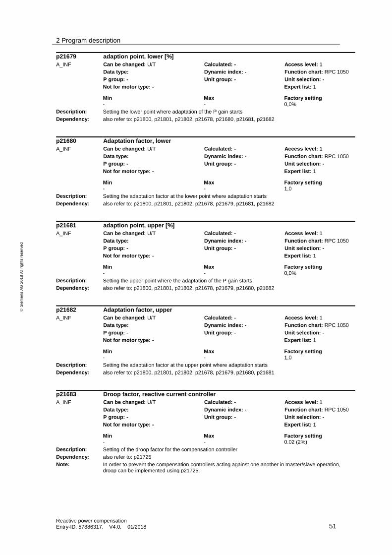
2 Program description
Reactive power compensation Entry-ID: 57886317, V4.0, 01/2018 51
S
iem
en
s A
G 2
01
8 A
ll ri
gh
ts r
ese
rve
d
p21679 adaption point, lower [%]
A_INF Can be changed: U/T Calculated: - Access level: 1
Data type: Dynamic index: - Function chart: RPC 1050
P group: - Unit group: - Unit selection: -
Not for motor type: - Expert list: 1
Min Max Factory setting - - 0,0%
Description: Setting the lower point where adaptation of the P gain starts
Dependency: also refer to: p21800, p21801, p21802, p21678, p21680, p21681, p21682
p21680 Adaptation factor, lower
A_INF Can be changed: U/T Calculated: - Access level: 1
Data type: Dynamic index: - Function chart: RPC 1050
P group: - Unit group: - Unit selection: -
Not for motor type: - Expert list: 1
Min Max Factory setting - - 1,0
Description: Setting the adaptation factor at the lower point where adaptation starts
Dependency: also refer to: p21800, p21801, p21802, p21678, p21679, p21681, p21682
p21681 adaption point, upper [%]
A_INF Can be changed: U/T Calculated: - Access level: 1
Data type: Dynamic index: - Function chart: RPC 1050
P group: - Unit group: - Unit selection: -
Not for motor type: - Expert list: 1
Min Max Factory setting - - 0,0%
Description: Setting the upper point where the adaptation of the P gain starts
Dependency: also refer to: p21800, p21801, p21802, p21678, p21679, p21680, p21682
p21682 Adaptation factor, upper
A_INF Can be changed: U/T Calculated: - Access level: 1
Data type: Dynamic index: - Function chart: RPC 1050
P group: - Unit group: - Unit selection: -
Not for motor type: - Expert list: 1
Min Max Factory setting - - 1,0
Description: Setting the adaptation factor at the upper point where adaptation starts
Dependency: also refer to: p21800, p21801, p21802, p21678, p21679, p21680, p21681
p21683 Droop factor, reactive current controller
A_INF Can be changed: U/T Calculated: - Access level: 1
Data type: Dynamic index: - Function chart: RPC 1050
P group: - Unit group: - Unit selection: -
Not for motor type: - Expert list: 1
Min Max Factory setting - - 0.02 (2%)
Description: Setting of the droop factor for the compensation controller
Dependency: also refer to: p21725
Note: In order to prevent the compensation controllers acting against one another in master/slave operation, droop can be implemented using p21725.
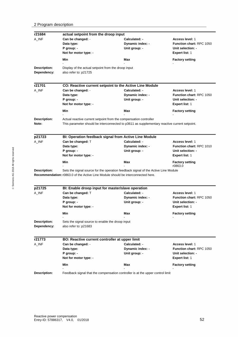
2 Program description
Reactive power compensation Entry-ID: 57886317, V4.0, 01/2018 52
S
iem
en
s A
G 2
01
8 A
ll ri
gh
ts r
ese
rve
d
r21684 actual setpoint from the droop input
A_INF Can be changed: - Calculated: - Access level: 1
Data type: Dynamic index: - Function chart: RPC 1050
P group: - Unit group: - Unit selection: -
Not for motor type: - Expert list: 1
Min Max Factory setting - - -
Description: Display of the actual setpoint from the droop input
Dependency: also refer to: p21725
r21701 CO: Reactive current setpoint to the Active Line Module
A_INF Can be changed: - Calculated: - Access level: 1
Data type: Dynamic index: - Function chart: RPC 1050
P group: - Unit group: - Unit selection: -
Not for motor type: - Expert list: 1
Min Max Factory setting - - -
Description: Actual reactive current setpoint from the compensation controller
Note: This parameter should be interconnected to p3611 as supplementary reactive current setpoint.
p21723 BI: Operation feedback signal from Active Line Module
A_INF Can be changed: T Calculated: - Access level: 1
Data type: Dynamic index: - Function chart: RPC 1010
P group: - Unit group: - Unit selection: -
Not for motor type: - Expert list: 1
Min Max Factory setting - - r0863.0
Description: Sets the signal source for the operation feedback signal of the Active Line Module
Recommendation: r0863.0 of the Active Line Module should be interconnected here.
p21725 BI: Enable droop input for master/slave operation
A_INF Can be changed: T Calculated: - Access level: 1
Data type: Dynamic index: - Function chart: RPC 1050
P group: - Unit group: - Unit selection: -
Not for motor type: - Expert list: 1
Min Max Factory setting - - -
Description: Sets the signal source to enable the droop input
Dependency: also refer to: p21683
r21773 BO: Reactive current controller at upper limit
A_INF Can be changed: - Calculated: - Access level: 1
Data type: Dynamic index: - Function chart: RPC 1050
P group: - Unit group: - Unit selection: -
Not for motor type: - Expert list: 1
Min Max Factory setting - - -
Description: Feedback signal that the compensation controller is at the upper control limit

2 Program description
Reactive power compensation Entry-ID: 57886317, V4.0, 01/2018 53
S
iem
en
s A
G 2
01
8 A
ll ri
gh
ts r
ese
rve
d
r21774 BO: Reactive current controller at the lower limit
A_INF Can be changed: - Calculated: - Access level: 1
Data type: Dynamic index: - Function chart: RPC 1050
P group: - Unit group: - Unit selection: -
Not for motor type: - Expert list: 1
Min Max Factory setting - - -
Description: Feedback signal that the compensation controller is at the lower control limit
p21800 Proportional action coefficient, reactive power control [A/kvar]
A_INF Can be changed: U/T Calculated: - Access level: 1
Data type: Dynamic index: - Function chart: RPC 1050
P group: - Unit group: - Unit selection: -
Not for motor type: - Expert list: 1
Min Max Factory setting - - 1,0
Description: Setting of the gain factor for the reactive current controller when reactive power control is enabled
Note: For an inverted sign of the externally acquired actual reactive power value, a negative value can be set here in order to correct the control sense again.
p21801 Proportional action coefficient, cos phi control [A]
A_INF Can be changed: U/T Calculated: - Access level: 1
Data type: Dynamic index: - Function chart: RPC 1050
P group: - Unit group: - Unit selection: -
Not for motor type: - Expert list: 1
Min Max Factory setting - - 1.3
Description: Setting of the gain factor for the reactive current controller when power factor control is enabled
Note: For an inverted sign of the externally acquired actual reactive power value, a negative value can be set here in order to correct the control sense again.
p21803 integral time, reactive current controller [ms]
A_INF Can be changed: U/T Calculated: - Access level: 1
Data type: Dynamic index: - Function chart: RPC 1050
P group: - Unit group: - Unit selection: -
Not for motor type: - Expert list: 1
Min Max Factory setting - - 1000 ms
Description: Setting of the integral time for the compensation controller

2 Program description
Reactive power compensation Entry-ID: 57886317, V4.0, 01/2018 54
S
iem
en
s A
G 2
01
8 A
ll ri
gh
ts r
ese
rve
d
2.3 Faults and alarms
F51050 The reference current of the infeed is zero
Drive object: A_INF
Response: OFF2
Acknowledgement: IMMEDIATELY
Cause: The reference current of the Active Line Module is not interconnected at p21630.
Remedy Interconnect p21630 with r2702 of the Active Line Module

3 Appendix
Reactive power compensation Entry-ID: 57886317, V4.0, 01/2018 55
S
iem
en
s A
G 2
01
8 A
ll ri
gh
ts r
ese
rve
d
3 Appendix
3.1 Service and Support
Industry Online Support
Do you have any questions or need assistance?
Siemens Industry Online Support offers round the clock access to our entire service and support know-how and portfolio.
The Industry Online Support is the central address for information about our products, solutions and services.
Product information, manuals, downloads, FAQs, application examples and videos – all information is accessible with just a few mouse clicks at: https://support.industry.siemens.com
Technical Support
The Technical Support of Siemens Industry provides you fast and competent support regarding all technical queries with numerous tailor-made offers – ranging from basic support to individual support contracts. You send queries to Technical Support via Web form: www.siemens.com/industry/supportrequest
SITRAIN – Training for Industry
With our globally available training courses for our products and solutions, we help you achieve with practical experience, innovative learning methods and a concept that’s tailored to the customer’s specific needs.
For more information on our offered trainings and courses, as well as their locations and dates, refer to: www.siemens.com/sitrain
Service offer
Our range of services includes the following:
Plant data services
Spare parts services
Repair services
On-site and maintenance services
Retrofitting and modernization services
Service programs and contracts
You can find detailed information on our range of services in the service catalog: https://support.industry.siemens.com/cs/sc
Industry Online Support app
You will receive optimum support wherever you are with the "Siemens Industry Online Support" app. The app is available for Apple iOS, Android and Windows Phone: https://support.industry.siemens.com/cs/ww/en/sc/2067

3 Appendix
Reactive power compensation Entry-ID: 57886317, V4.0, 01/2018 56
S
iem
en
s A
G 2
01
8 A
ll ri
gh
ts r
ese
rve
d
3.2 Application Support
Siemens AG Digital Factory Division Factory Automation Production Machines DF FA PMA APC Frauenauracher Str. 80 91056 Erlangen, Germany
mailto: [email protected]
3.3 Links and Literature
Table 3-1
No. Topic
\1\ Siemens Industry Online Support
https://support.industry.siemens.com
\2\ Link to this entry page of this application example
https://support.industry.siemens.com/cs/ww/en/view/57886317
\3\ SINAMICS S120 System Manual Grid Infeed
https://support.industry.siemens.com/cs/ww/en/view/109476635
3.4 Change documentation
Table 3-2
Version Date Modifications
V1.0 01/2012 First Version
V2.0 05/2012 Selection of closed loop control methods
V3.0 06/2015 Sensing of power factor actual values switched to VSM10
V4.0 01/2018 using signed cos phi value, stable closed loop control also with changing actual power signs, improved documentation of signs for setpoints