Simultaneous X-ray fluorescence and ptychographic...
10
Simultaneous X-ray fluorescence and ptychographic microscopy of Cyclotella meneghiniana D. J. Vine, 1,2,3,∗ D. Pelliccia, 1,4 C. Holzner, 5 S. B. Baines, 6 A. Berry, 7 I. McNulty, 3 S. Vogt, 3 A. G. Peele, 1,8,9 and K. A. Nugent 1,2,9 1 Australian Research Council Centre of Excellence for Coherent X-ray Science Australia 2 School of Physics, The University of Melbourne, Parkville, Victoria 3010, Australia 3 The Advanced Photon Source, Argonne National Lab, Argonne, IL 60439, USA 4 School of Physics, Monash University, Clayton, Victoria 3800, Australia 5 Xradia, Inc., 4385 Hopyard Road, Pleasanton, CA 94588, USA 6 Department of Ecology and Evolution, Stony Brook University, Stony Brook, NY 11794, USA 7 Monash Centre for Synchrotron Science, Monash University, Clayton, VIC 3800, Australia 8 Department of Physics, La Trobe University, Bundoora, Victoria 3086, Australia 9 Australian Synchrotron, Clayton, Victoria 3168, Australia ∗ [email protected] Abstract: Scanning X-ray fluorescence microscopy (XFM) is a particu- larly useful method for studying the spatial distribution of trace metals in biological samples. Here we demonstrate the utility of combining coherent diffractive imaging (CDI) with XFM for imaging biological samples to simultaneously produce high-resolution and high-contrast transmission images and quantitative elemental maps. The reconstructed transmission function yields morphological details which contextualise the elemental maps. We report enhancement of the spatial resolution in both the trans- mission and fluorescence images beyond that of the X-ray optics. The freshwater diatom Cyclotella meneghiniana was imaged to demonstrate the benefits of combining these techniques that have complementary contrast mechanisms. © 2012 Optical Society of America OCIS codes: (340.7440) X-ray imaging; (340.7460) X-ray microscopy; (180.5810) Scanning microscopy; (180.7460) X-ray microscopy; (300.6560) Spectroscopy, x-ray. References and links 1. T. Paunesku, S. Vogt, J. Maser, B. Lai, and G. Woloschak, “X-ray fluorescence microprobe imaging in biology and medicine,” J. Cell Biochem. 99, 1489–1502 (2006). 2. B. S. Twining, S. B. Baines, N. S. Fisher, J. Maser, S. Vogt, C. Jacobsen, A. Tovar-Sanchez, and S. A. Sa¯ nudo- Wilhelmy, “Quantifying trace elements in individual aquatic protist cells with a synchrotron x-ray fluorescence microprobe,” Anal. Chem. 75, 3806–3816 (2003). 3. H. N. Chapman and K. A. Nugent, “Coherent lensless x-ray imaging,” Nat. Photonics 4, 833–839 (2010). 4. S. W. Hell, “Far-field optical nanoscopy,” Science 316, 1153–1158 (2007). 5. M. Bates, B. Huang, G. T. Dempsey, and X. Zhuang, “Multicolor super-resolution imaging with photo-switchable fluorescent probes,” Science 317, 1749–1753 (2007). 6. B. Huang, W. Wang, M. Bates, and X. Zhuang, “Three-dimensional super-resolution imaging by stochastic opti- cal reconstruction microscopy,” Science 319, 810–813 (2008). 7. A. A. Snigirev, I. I. Snigreva, V. G. Kohn, S. Kuznetsov, and I. A. Schelokov, “On the possibilities of x-ray phase contrast microimaging by coherent high-energy synchrotron radiation,” Rev. Sci. Instrum. 66, 5486–5492 (1995). #168500 - $15.00 USD Received 14 May 2012; revised 21 Jun 2012; accepted 22 Jun 2012; published 25 Jul 2012 (C) 2012 OSA 30 July 2012 / Vol. 20, No. 16 / OPTICS EXPRESS 18287
Transcript of Simultaneous X-ray fluorescence and ptychographic...

Simultaneous X-ray fluorescence andptychographic microscopy of Cyclotella
meneghiniana
D. J. Vine,1,2,3,∗ D. Pelliccia,1,4 C. Holzner,5 S. B. Baines,6 A. Berry,7 I.McNulty,3 S. Vogt,3 A. G. Peele,1,8,9 and K. A. Nugent1,2,9
1 Australian Research Council Centre of Excellence for Coherent X-ray Science Australia2 School of Physics, The University of Melbourne, Parkville, Victoria 3010, Australia
3 The Advanced Photon Source, Argonne National Lab, Argonne, IL 60439, USA4 School of Physics, Monash University, Clayton, Victoria 3800, Australia
5 Xradia, Inc., 4385 Hopyard Road, Pleasanton, CA 94588, USA6 Department of Ecology and Evolution, Stony Brook University, Stony Brook, NY 11794, USA
7 Monash Centre for Synchrotron Science, Monash University, Clayton, VIC 3800, Australia8 Department of Physics, La Trobe University, Bundoora, Victoria 3086, Australia
9 Australian Synchrotron, Clayton, Victoria 3168, Australia∗[email protected]
Abstract: Scanning X-ray fluorescence microscopy (XFM) is a particu-larly useful method for studying the spatial distribution of trace metals inbiological samples. Here we demonstrate the utility of combining coherentdiffractive imaging (CDI) with XFM for imaging biological samples tosimultaneously produce high-resolution and high-contrast transmissionimages and quantitative elemental maps. The reconstructed transmissionfunction yields morphological details which contextualise the elementalmaps. We report enhancement of the spatial resolution in both the trans-mission and fluorescence images beyond that of the X-ray optics. Thefreshwater diatom Cyclotella meneghiniana was imaged to demonstrate thebenefits of combining these techniques that have complementary contrastmechanisms.
© 2012 Optical Society of America
OCIS codes: (340.7440) X-ray imaging; (340.7460) X-ray microscopy; (180.5810) Scanningmicroscopy; (180.7460) X-ray microscopy; (300.6560) Spectroscopy, x-ray.
References and links1. T. Paunesku, S. Vogt, J. Maser, B. Lai, and G. Woloschak, “X-ray fluorescence microprobe imaging in biology
and medicine,” J. Cell Biochem. 99, 1489–1502 (2006).2. B. S. Twining, S. B. Baines, N. S. Fisher, J. Maser, S. Vogt, C. Jacobsen, A. Tovar-Sanchez, and S. A. Sanudo-
Wilhelmy, “Quantifying trace elements in individual aquatic protist cells with a synchrotron x-ray fluorescencemicroprobe,” Anal. Chem. 75, 3806–3816 (2003).
3. H. N. Chapman and K. A. Nugent, “Coherent lensless x-ray imaging,” Nat. Photonics 4, 833–839 (2010).4. S. W. Hell, “Far-field optical nanoscopy,” Science 316, 1153–1158 (2007).5. M. Bates, B. Huang, G. T. Dempsey, and X. Zhuang, “Multicolor super-resolution imaging with photo-switchable
fluorescent probes,” Science 317, 1749–1753 (2007).6. B. Huang, W. Wang, M. Bates, and X. Zhuang, “Three-dimensional super-resolution imaging by stochastic opti-
cal reconstruction microscopy,” Science 319, 810–813 (2008).7. A. A. Snigirev, I. I. Snigreva, V. G. Kohn, S. Kuznetsov, and I. A. Schelokov, “On the possibilities of x-ray phase
contrast microimaging by coherent high-energy synchrotron radiation,” Rev. Sci. Instrum. 66, 5486–5492 (1995).
#168500 - $15.00 USD Received 14 May 2012; revised 21 Jun 2012; accepted 22 Jun 2012; published 25 Jul 2012(C) 2012 OSA 30 July 2012 / Vol. 20, No. 16 / OPTICS EXPRESS 18287
8. B. Hornberger, M. D. de Jonge, M. Feser, P. Holl, C. Jacobsen, D. Legnini, P. Rehak, L. Struder, and S. Vogt,“Differential phase contrast with a segmented detector in a scanning x-ray microprobe,” J. Synch. Rad. 15, 355–362 (2008).
9. C. Holzner, M. Feser, S. Vogt, B. Hornberger, S. B. Baines, and C. Jacobsen, “Zernike phase contrast in scanningmicroscopy with x-rays,” Nat. Phys. 6, 883–887 (2010).
10. J. Miao, D. Sayre, and H. N. Chapman, “Phase retrieval from the magnitude of the Fourier transforms of nonpe-riodic objects,” J. Opt. Soc. Am. A 15, 1662–1669 (1998).
11. J. Miao, P. Charalambous, J. Kirz, and D. Sayre, “Extending the methodology of x-ray crystallography tomicrometre-sized non-crystalline specimens,” Nature 400, 342–344 (1999).
12. I. K. Robinson, I. A. Vartanyants, G. J. Williams, M. A. Pfeifer, and J. A. Pitney, “Reconstruction of the shapesof gold nanocrystals using coherent x-ray diffraction,” Phys. Rev. Lett. 87, 195505 (2001).
13. G. J. Williams, H. M. Quiney, B. B. Dhal, C. Q. Tran, K. A. Nugent, A. G. Peele, D. Paterson, and M. D. de Jonge,“Fresnel coherent diffractive imaging,” Phys. Rev. Lett. 97, 025506 (2006).
14. K. A. Nugent, “Coherent methods in the x-ray sciences,” Adv. Phys. 59, 1–99 (2010).15. H. M. L. Faulkner and J. M. Rodenburg, “Error tolerance of an iterative phase retrieval algorithm for movable
illumination microscopy,” Ultramicroscopy 103, 153–164 (2005).16. P. Thibault, M. Dierolf, A. Menzel, O. Bunk, C. David, and F. Pfeiffer, “High resolution scanning x-ray diffrction
microscopy,” Science 321, 379–382 (2008).17. D. J. Vine, G. J. Williams, B. Abbey, M. A. Pfeifer, J. N. Clark, M. D. De Jonge, I. McNulty, A. G. Peele, and
K. A. Nugent, “Ptychographic Fresnel coherent diffractive imaging,” Phys. Rev. A 80, 063823 (2009).18. Factorising the exit surface wave into the product of the incident beam multiplied by the sample transmission
function requires assuming the sample is sufficiently thin for the projection approximation to hold [14, 34, 35].19. P. Thibault, M. Dierolf, O. Bunk, A. Menzel, and F. Pfeiffer, “Probe retrieval in ptychographic coherent diffractive
imaging,” Ultramicroscopy 109, 338–343 (2009).20. L. Hare, “Aquatic insects and trace metals: Bioavailability, bioaccumulation, and toxicity,” Crc. Cr. Rev. Toxicol.
22, 327–369 (1992).21. K. H. Thompson and C. Orvig, “Boon and bane of metal ions in medicine,” Science 300, 936–939 (2003).22. A. Schropp, P. Boye, A. Goldschmidt, S. Honig, R. Hoppe, J. Patommel, C. Rakete, D. Samberg, S. Stephan,
S. Schroder, M. Burghammer, and C. Schroer, “Non-destructive and quantitative imaging of a nano-structuredmicrochip by ptychographic hard x-ray scanning microscopy,” J. Microsc. 241, 9–12 (2011).
23. X. Llopart, M. Campbell, R. Dinapoli, D. San Segundo, and E. Pernigotti, “Medipix2: A 64-k pixel readout chipwith 55 μm square elements working in single photon counting mode,” IEEE T. Nucl. Sci. 49, 2279–2283 (2002).
24. C. B. Field, M. J. Behrenfeld, J. T. Randerson, and P. Falkowski, “Primary production of the biosphere: Integrat-ing terrestrial and oceanic components,” Science 281, 237–240 (1998).
25. R. A. Armstrong, C. Lee, J. I. Hedges, S. Honjo, and S. G. Wakeham, “A new, mechanistic model for organiccarbon fluxes in the ocean based on the quantitative association of POC with ballast minerals,” Deep-Sea Res.Pt.2 49, 219–236 (2002).
26. K. O. Buesseler, “The decoupling of production and particulate export in the surface ocean,” Global Biogeochem.Cy. 12, 297–310 (1998).
27. J. Nagy and Z. Strakos, “Enforcing nonnegativity in image reconstruction algorithms,” in Proc. SPIE 4121 (2000).28. C. Ryan, R. Kirkham, R. Hough, G. Moorhead, D. Siddons, M. de Jonge, D. Paterson, G. De Geronimo,
D. Howard, and J. Cleverley, “Elemental x-ray imaging using the maia detector array: The benefits and chal-lenges of large solid-angle,” Nucl. Instrum. Meth. A 619, 37–43 (2010).
29. W. Vernon, M. Allin, R. Hamlin, T. Hontz, D. Nguyen, F. Augustine, S. M. Gruner, N. H. Xuong, D. R. Schuette,M. W. Tate, and L. J. Koerner, “First results from the 128x128 pixel mixed-mode Si x-ray detector chip,” Proc.SPIE 6706, 67060U (2007).
30. M. D. de Jonge, C. Holzner, S. B. Baines, B. S. Twining, K. Ignatyev, J. Diaz, D. L. Howard, D. Legnini,A. Miceli, I. McNulty, C. J. Jacobsen, and S. Vogt, “Quantitative 3D elemental microtomography of cyclotellameneghiniana at 400-nm resolution,” P. Natl. Acad. Sci. USA 107, 15676–15680 (2010).
31. R. W. Gerchberg and W. O. Saxton, “A practical algorithm for the determination of phase from image anddiffraction plane pictures,” Optik 35, 237–246 (1972).
32. J. Fienup, T. Crimmins, and W. Holsztynski, “Reconstruction of the support of an object from the support of itsautocorrelation,” J. Opt. Soc. Am. A 72, 610–624 (1982).
33. H. M. L. Faulkner and J. M. Rodenburg, “Movable aperture lens transmission microscopy: A novel phase retrievalalgorithm,” Phys. Rev. Lett. 93, 023903 (2004).
34. J. M. Cowley, Diffraction Physics, 3rd ed. (North-Holland Publishing Company, Amsterdam, 1995).35. D. M. Paganin, Coherent X-Ray Optics (Oxford University Press, New York, 2006).
Scanning hard X-ray fluorescence microscopy (XFM) is an increasingly important tool forstudying the role of trace elements in biological and biomedical research [1]. It is known thattrace metals are involved in most intracellular processes however there has been a dearth of
#168500 - $15.00 USD Received 14 May 2012; revised 21 Jun 2012; accepted 22 Jun 2012; published 25 Jul 2012(C) 2012 OSA 30 July 2012 / Vol. 20, No. 16 / OPTICS EXPRESS 18288

tools with the sensitivity required to quantify them at the nanoscale. XFM allows cells andorganisms to be studied in close to their natural state, permitting the detection of just a fewthousand atoms [2] and so obviating the need for tags or dyes. Coherent diffractive imaging(CDI) is a type of microscopy that is able to form images without the need for lenses andtherefore with a spatial resolution which is, in principle, limited only by the wavelength ofthe incident light [3]. Here we demonstrate the utility of combining CDI and XFM for imag-ing biological samples to produce high-resolution and high-contrast transmission images andquantitative elemental maps. The reconstructed transmission function yields morphological de-tails which contextualise the elemental maps. We report enhancement of the spatial resolutionin both the transmission and fluorescence images beyond that of the X-ray optics. Unlike op-tical super-resolution methods [4–6] this approach is not limited to imaging samples whichexpress fluorescent proteins. For the transmission images the resolution is 30 nm, a factor ofeight smaller than the focused beam diameter. In addition, we show that the reconstructed X-ray beam amplitude can be used to gain a factor of two improvement in the spatial resolutionof the elemental maps to 155 nm. We image the freshwater diatom Cyclotella meneghinianato demonstrate the benefits of combining these techniques that have complementary contrastmechanisms.
Scanning X-ray microprobes form images by raster-scanning a focused X-ray beam over asample while the transmitted beam and secondary emission are recorded. In X-ray fluorescencemicroscopy the secondary fluorescence signal is used to quantify the elemental concentrationwhile the transmitted beam carries information about the projected electron density. The trans-mitted X-ray beam carries a significant amount of information that is complementary to thefluorescence signal. Light elements in the sample such as C, N and O that are much more dif-ficult to map by their fluorescence can still be detected from the phase shift they impart to theincident X-rays.
Since the initial demonstration experiments [7] phase contrast X-ray imaging has foundwidespread use because refraction can be the dominant contrast mechanism for hard X-rays.The traditional approach to measuring a phase contrast signal in a scanning microscope in-volves measuring the average refraction over the focal spot [8] but this method under-utilizesthe scattering information available. A recent demonstration of Zernike phase contrast in thescanning geometry more fully utilizes the scattered signal [9]. Coherent diffractive imaging is anew technique that provides the full complex exit surface wave from the object without the useof an image-forming objective lens. Imaging by CDI involves recording the coherent diffractionpattern of the object then reconstructing its image on a computer using an iterative algorithmto retrieve the missing phases from the diffraction data through the imposition of known con-straints on the sample transmission function [10–14]. The reconstructed exit surface wave givesa quantitative measure of the attenuation and phase shift at a spatial resolution determined bythe numerical aperture (NA) of the detector which can easily be much larger than that of thehighest resolution X-ray optics currently available.
Recent developments in scanning CDI make the approach entirely compatible with XFM.In scanning CDI, diffraction patterns are recorded with some overlap of the incident X-rayprobe between adjacent measurement points [15–17]. By constraining the reconstructions tobe mutually consistent in the overlap region one can reconstruct an unlimited field of viewwithout any a priori information about the sample [18]. The set of diffraction patterns mayalso be analysed to extract the complex wavefield describing the probe in the sample planesimultaneously [19]. Recording a far-field diffraction pattern at every scan point in an XFMexperiment allows a high-resolution and phase sensitive image to be reconstructed with littleadditional experimental overhead.
The benefit of this approach, scanning multi-modal X-ray microscopy (SMXM), derives
#168500 - $15.00 USD Received 14 May 2012; revised 21 Jun 2012; accepted 22 Jun 2012; published 25 Jul 2012(C) 2012 OSA 30 July 2012 / Vol. 20, No. 16 / OPTICS EXPRESS 18289

from the complementary contrast mechanisms of the two techniques. The soft X-ray fluores-cence from low-Z biomass elements (C,N,O) are difficult to detect due to low fluorescenceyields and strong absorption by the sample itself. The transmitted X-rays however are sensitiveto the electron density so that even though these elements interact weakly they are present insufficient quantity to be detected using phase contrast. Trace metals can then be associated withspecific cellular functions by correlating spatial distributions of trace metals with cell struc-tures that perform specific cellular processes. The ability to determine the location of metalswith respect to cell structure in high resolution is a significant new capability. The applicationsfor such an advance range from studying the uptake and subsequent transfer of metals withinnatural food webs [20] to evaluating the effectiveness of designer drugs which contain metals asactive agents [21]. Earlier work has also demonstrated the benefits of combining ptychographyand fluorescence mapping for materials science applications [22].
Fig. 1. Simultaneous ptychographic and fluorescence microscopy. A focused X-raybeam is scanned across a sample whilst simultaneously recording the X-ray fluorescencespectra and coherent diffraction pattern.
An SMXM experiment was performed at beamline 2-ID-E of the Advanced Photon Sourceusing the experimental geometry sketched in Fig. 1 (for details see Appendix). SMXM usesa similar setup to XFM - the only notable difference is the introduction of a pixellated areadetector to record the transmitted X-rays. A 7.7 keV X-ray beam was focused by a 160 μm-diameter zone plate lens with an outermost zone width of 100 nm. A 50 μm aperture wasplaced 0.5 m upstream of the zone plate to ensure it was coherently illuminated. The coherenceselecting aperture apodized the lens so that the focused beam size, 250nm as measured bya knife edge scan, was much larger than the outermost zone width. The focused beam wasthen scanned across the sample and at each point in the scan a photon counting pixel arraydetector [23] (2562 55 μm pixels) located 1.34 m downstream of the focus recorded a far-field diffraction pattern as an energy dispersive silicon drift diode measured the fluorescencespectrum.
To explore the improvement in spatial resolution of the transmitted image using SMXMwe imaged several regions of a gold spoked “star” resolution pattern, Fig. 2. The sample wasraster scanned through a 31×31 grid using a step size of 100 nm and exposure times of 100ms (transmitted) and 1 s (fluorescence). The data were reconstructed (see Appendix) and theresults are shown in Fig. 2. The first column (Figs. 2(a) and 2(d)) show the transmitted image.The second column (Figs. 2(b) and 2(e)) show the fluorescence image. There is little structurevisible in either of these data sets consistent with the expected resolution of the zone plate.The third column (Figs. 2(c) and 2(e)) shows the reconstructed intensity in the sample plane;the dramatic improvement in resolution (in this data a factor of 8 increase) is obvious. The
#168500 - $15.00 USD Received 14 May 2012; revised 21 Jun 2012; accepted 22 Jun 2012; published 25 Jul 2012(C) 2012 OSA 30 July 2012 / Vol. 20, No. 16 / OPTICS EXPRESS 18290

Fig. 2. Imaging below the lens resolution. (Rows: Top, Bottom) Two different areas ofa gold spoked resolution target, (Columns Left-Right): the scanning transmission image(a,d), the gold M-edge fluorescence (b, e) and the sample exit surface intensity recon-structed using ptychography (c, f). The spacing of the inner ring of spokes in (c) is 30nm.(a) Inset shows the reconstructed probe intensity (log scale).
inset shows the reconstruction of the probe beam (see Appendix). The 30 nm features at thecenter of the star pattern are resolved, however the bifurcation of some spokes in the inner ringare artifacts which we believe are caused by the sample positioning system. The evident skewdistortion of the circular features is due to a slight misalignment between the horizontal andvertical travel of the scan stages.
We then imaged the diatom Cyclotella meneghiniana, a common siliceous freshwater mi-croalgae. Diatoms play an important role in global material and energy cycles. For exam-ple, marine diatoms account for 40% of the photosynthesis in the ocean and 20% of that onearth [24]. Due to their dense silica cell walls, they also facilitate the movement of organicmaterial to depth via sinking particles [25, 26]. Where trace concentrations of Fe and Mn lo-calize and their role in the life-cycle of Cyclotella m. are key questions determining how thesemicroalgae sequester and organize the silica and thus their propensity to sink. Scanning XFMcan determine the locations of these important transition metals within the diatom, but in orderto quantify their concentrations the remainder of the diatom mass (principally made of lightelements) must be determined. The data in Fig. 3 shows the concentrations of major biomassconstituents including Si, P, S and K, trace amounts of F and Mn, and the complex transmissionfunction. The SMXM scan consisted of 121× 101 points with 100 nm step size and 130 ms(transmission) and 1 s (fluorescence) exposure times. The attenuation image in Fig. 3(a) showspoor contrast because this sample is almost transparent to hard X-rays. The phase is more sen-sitive to the internal structure of the diatom as expected at this energy. The Fresnel fringingevident in Fig. 3(a) is due to the plane of the reconstruction being in the near field of some ofthe small or sharp features. That the sample is in the focal waist of the zone plate can be verifiedby propagating the reconstructed probe through focus (see Appendix).
#168500 - $15.00 USD Received 14 May 2012; revised 21 Jun 2012; accepted 22 Jun 2012; published 25 Jul 2012(C) 2012 OSA 30 July 2012 / Vol. 20, No. 16 / OPTICS EXPRESS 18291

Fig. 3. Morphological structure and elemental composition of a freshwater diatom. (a)& (b) the reconstructed amplitude (arb. units) and phase (rad) of the sample exit surfacewave respectively, (c) the X-ray absorption contrast and fluorescence maps (inset text de-scribes element and image minimum, maximum). The reconstructed transmission imagesclearly show features not easily resolved in the fluorescence maps such as the diatom wallthickness and a low density cavity surrounded by a much more dense wall.
In XFM the spatial resolution is limited by the size of the probe beam used to map the spec-imen. In this work we show that the spatial resolution of the elemental maps obtained by XFMmay be significantly improved by deconvolving the reconstructed probe beam. The point spreadfunction (PSF) of the X-ray fluorescence microscope can be estimated from the squared mag-nitude of the incident X-ray probe and the overlap between scan positions required for the CDIreconstruction. Figure 4 presents an almost twofold improvement in the spatial resolution ofthe elemental maps that was achieved by deconvolution to remove the blur caused by the finiteextent of the incident probe. Figures 4(c), 4(e) and 4(f) have been rescaled from the step scanresolution of 101×121 100 nm pixels to the pixel size of the transmission image (15 nm) usingbilinear interpolation. The interpolation step does not add any new information and as such doesnot increase the spatial resolution. The point spread function was then deconvolved [27] fromthe interpolated images to give Fig. 4(d), 4(f) and 4(h). The resolution improvement estimatedfrom the diatom wall is approximately 40% or 155 nm. Barely visible features such as the band-ing in the diatom frustule are clearly visible post-deconvolution. Agreement between the sizeof features visible in the deconvolved XFM data and the independently measured transmissionfunction attest to the accuracy of the deconvolution.
We have demonstrated the benefits of multi-modal imaging for biological samples. SMXMcombines XFM and ptychography to yield nanoscale phase sensitive maps with elementalspecificity. The high resolution transmission images reveal sample structure which providescontext for the elemental maps. The reconstructed X-ray probe can be used to super resolve theelemental maps significantly better than the size of the focused probe, and hence the diffractionlimit of the imaging system. Because this measurement requires no additional time overhead to
#168500 - $15.00 USD Received 14 May 2012; revised 21 Jun 2012; accepted 22 Jun 2012; published 25 Jul 2012(C) 2012 OSA 30 July 2012 / Vol. 20, No. 16 / OPTICS EXPRESS 18292
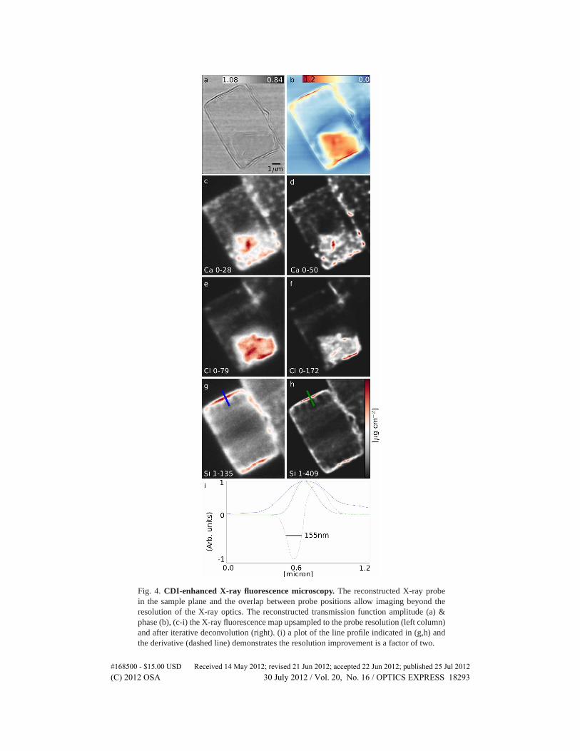
Fig. 4. CDI-enhanced X-ray fluorescence microscopy. The reconstructed X-ray probein the sample plane and the overlap between probe positions allow imaging beyond theresolution of the X-ray optics. The reconstructed transmission function amplitude (a) &phase (b), (c-i) the X-ray fluorescence map upsampled to the probe resolution (left column)and after iterative deconvolution (right). (i) a plot of the line profile indicated in (g,h) andthe derivative (dashed line) demonstrates the resolution improvement is a factor of two.
#168500 - $15.00 USD Received 14 May 2012; revised 21 Jun 2012; accepted 22 Jun 2012; published 25 Jul 2012(C) 2012 OSA 30 July 2012 / Vol. 20, No. 16 / OPTICS EXPRESS 18293

a typical XFM measurement and involves only the adoption of an area detector to record the co-herently diffracted signal we anticipate it may find widespread adoption on X-ray fluorescencemicroscopes.
The resolution is limited only by the diffracted signal and precision of the specimen scanstage, thus we envision further improvements will be made due to the rapid advances in x-raydispersive detector, area detector, and nanopositioning technology underway [28, 29]. Finally,we observe that the interior complexity of biological cells and sub-cellular organelles is justbeginning to be understood. Extension of this methodology to three-dimensional imaging bytomographic methods [30] is straightforward, opening the door to understanding the compart-mentalization and function of metals and other trace elements in biology.
Appendix
Experimental apparatus
All experiments were carried out at beamline 2-ID-E of the Advanced Photon Source. X-raysfrom a 3.3 cm period undulator were reflected from a mirror to remove high orders contribu-tions to the energy spectrum and a 7.7 keV monochromatic beam was selected using a singlereflection from a Si(111) single crystal.
A 50 μm aperture was used to select partially coherent illumination of a zone plate lens usedto focus the beam to approximately 250 μm at a distance of 0.5 m. The coherence selectingaperture was located a distance of 57 m from the source with dimensions of approximately270(h)×11(v) μm. The zone plate diameter was 160 μm with an outermost zone width of100 nm. A 40 μm central stop and 20 μm order sorting aperture were used to select the firstdiffraction order from the zone plate for the experiment.
A Medipix2 pixel array detector with 256×256 55 μm pixels and a dynamic range of 11800counts was used to measure the coherent diffraction patterns. A low energy threshhold settingon the detector was used to discriminate thermal noise. The detector was placed 1.34 metresfrom the focal plane. The resulting NA of 5.3×10⁻³ corresponds to a pixel size in the sampleplane of 15.4 nm.
The sample was placed in a He filled chamber and scanned through the focal waist of theX-ray beam while the fluorescence and diffraction data were recorded. The complex wavefielddescribing the X-ray probe has been computationally propagated through focus as in Fig. 5to verify that we were in the focal plane as expected. From that measurement we determinedthe sample plane was with the 110μm focal depth of this lens. The fluorescence spectra weremeasured using a single element Vortex EX-60 silicon drift diode detector. The sample wasrotated by 15◦ from perpendicular to the beam axis to increase the solid angle of the fluores-cence detector as viewed from the sample. The step size in all scans was 100 nm and the scandimensions varied as reported with the data. A 100 nm step size corresponds to approximately60% overlap between adjacent scan points.
A whitefield (no sample) measurement was made at the beginning and end of each scan for500 exposures at the same exposure time as the sample exposures. The whitefield data wereaveraged for use in the phase retrieval algorithm.
Phase retrieval
Phase retrieval was performed using a modified version of the algorithm outlined in [16]. Inthe modified algorithm, alternating iterations of difference map and an error reduction (ER)algorithm [31, 32] were applied. The real space finite support constraint of ER was replacedwith the ptychographic overlap constraint [33].
Each reconstruction presented in this manuscript ran for 1000 iterations with the probe it-eratively updated beginning the 30-th iteration. The 31×31 reconstructions took on average 4
#168500 - $15.00 USD Received 14 May 2012; revised 21 Jun 2012; accepted 22 Jun 2012; published 25 Jul 2012(C) 2012 OSA 30 July 2012 / Vol. 20, No. 16 / OPTICS EXPRESS 18294

Fig. 5. Determining the reconstruction plane. By propagating the reconstructed X-rayprobe intensity through focus we can quantify the distance of the sample from the focalplane. Line profiles through the focal waist (log scale) (a) and through focal series withoptical axis running left to right (b), (c). The reconstructed probe in the sample plane (d).
hours on a single core processor using code written in Python. The 121× 101 scans took ap-proximately 24 hours to complete. The reconstruction was easily identifiable at the conclusionof the second iteration and convergence was achieved after just a few hundred iterations.
No additional constraints were used on the amplitude or phase of any of the wavefields.
Iterative deconvolution of the point spread function of X-ray fluorescence data
The forward problem of image formation in the X-ray fluorescence microscope can be formu-lated as a discrete convolution with two native length scales, Δx1 the pixel size of the step scanand Δx2 the pixel size of the reconstructed probe,
I1(uΔx1) = ∑v|P(uΔx1 − vΔx2)|2I2(vΔx2), (1)
where Ip is the intensity measured with resolution p and P is the probe amplitude.The deconvolution process involves first resampling the elemental maps from the step scan
resolution to the resolution of the probe and finally deconvolving the probe. Resampling thedata was done using bilinear interpolation after low pass filtering the data. The bilinear interpo-lation does not increase the spatial resolution of the images but rather ensures smooth variationbetween pixels in the rescaled image.
The probe was then deconvolved using the modified residual norm steepest descent algo-rithm (MRNSDA) [27] as implemented in the “Parallel Iterative Deconvolution” ImageJ pluginwritten by Piotr Wendykier.
#168500 - $15.00 USD Received 14 May 2012; revised 21 Jun 2012; accepted 22 Jun 2012; published 25 Jul 2012(C) 2012 OSA 30 July 2012 / Vol. 20, No. 16 / OPTICS EXPRESS 18295

Deconvolution attempts to solve an ill-posed problem and as such our deconvolved imageswere treated with cautious skepticism. We are confident that the features resolved by the de-convolution process are not artifacts because they are in agreement with the independentlyreconstructed CDI images.
Acknowledgments
Use of the Advanced Photon Source, an Office of Science User Facility operated for the U.S.Department of Energy (DOE) Office of Science by Argonne National Laboratory, was sup-ported by the U.S. DOE under Contract No. DE-AC02-06CH11357.
#168500 - $15.00 USD Received 14 May 2012; revised 21 Jun 2012; accepted 22 Jun 2012; published 25 Jul 2012(C) 2012 OSA 30 July 2012 / Vol. 20, No. 16 / OPTICS EXPRESS 18296