Simultaneous Tracking and Elasticity Parameter Estimation ...
8
HAL Id: hal-02495831 https://hal.inria.fr/hal-02495831v2 Submitted on 4 May 2020 HAL is a multi-disciplinary open access archive for the deposit and dissemination of sci- entific research documents, whether they are pub- lished or not. The documents may come from teaching and research institutions in France or abroad, or from public or private research centers. L’archive ouverte pluridisciplinaire HAL, est destinée au dépôt et à la diffusion de documents scientifiques de niveau recherche, publiés ou non, émanant des établissements d’enseignement et de recherche français ou étrangers, des laboratoires publics ou privés. Simultaneous Tracking and Elasticity Parameter Estimation of Deformable Objects Agniva Sengupta, Romain Lagneau, Alexandre Krupa, Eric Marchand, Maud Marchal To cite this version: Agniva Sengupta, Romain Lagneau, Alexandre Krupa, Eric Marchand, Maud Marchal. Simultaneous Tracking and Elasticity Parameter Estimation of Deformable Objects. ICRA 2020 - IEEE International Conference on Robotics and Automation, May 2020, Paris, France. pp.1-7. hal-02495831v2
Transcript of Simultaneous Tracking and Elasticity Parameter Estimation ...
HAL Id: hal-02495831https://hal.inria.fr/hal-02495831v2
Submitted on 4 May 2020
HAL is a multi-disciplinary open accessarchive for the deposit and dissemination of sci-entific research documents, whether they are pub-lished or not. The documents may come fromteaching and research institutions in France orabroad, or from public or private research centers.
L’archive ouverte pluridisciplinaire HAL, estdestinée au dépôt et à la diffusion de documentsscientifiques de niveau recherche, publiés ou non,émanant des établissements d’enseignement et derecherche français ou étrangers, des laboratoirespublics ou privés.
Simultaneous Tracking and Elasticity ParameterEstimation of Deformable Objects
Agniva Sengupta, Romain Lagneau, Alexandre Krupa, Eric Marchand, MaudMarchal
To cite this version:Agniva Sengupta, Romain Lagneau, Alexandre Krupa, Eric Marchand, Maud Marchal. SimultaneousTracking and Elasticity Parameter Estimation of Deformable Objects. ICRA 2020 - IEEE InternationalConference on Robotics and Automation, May 2020, Paris, France. pp.1-7. �hal-02495831v2�
Simultaneous Tracking and Elasticity Parameter Estimationof Deformable Objects
Agniva Sengupta∗1, Romain Lagneau∗2, Alexandre Krupa1, Eric Marchand1, Maud Marchal3
Abstract— In this paper, we propose a novel method to si-multaneously track the deformation of soft objects and estimatetheir elasticity parameters. The tracking of the deformableobject is performed by combining the visual informationcaptured by a RGB-D sensor with interactive Finite ElementMethod simulations of the object. The visual information ismore particularly used to distort the simulated object. Inparallel, the elasticity parameter estimation minimizes the errorbetween the tracked object and a simulated object deformedby the forces that are measured using a force sensor. Once theelasticity parameters are estimated, our tracking algorithm canbe used to estimate the deformation forces applied to an objectwithout the use of a force sensor. We validated our methodon several soft objects with different shape complexities. Ourevaluations show the ability of our method to estimate theelasticity parameters as well as its use to estimate the forcesapplied to a deformable object without any force sensor. Theseresults open novel perspectives to better track and controldeformable objects during robotic manipulations.
I. INTRODUCTION
Nowadays, robots are efficient in manipulating rigid ob-jects. However, simultaneous manipulation and tracking ofdeformable objects remains a challenging problem and couldimprove different applications, such as humanoid robotsinteracting with soft objects, compliance testing in productmanufacturing or detection of abnormal skin stiffness inpreventive healthcare. The aim of our approach is to auto-matically estimate the elasticity parameters of a soft objectthat is being deformed by the end-effector of a robot. For thatpurpose, we propose a closed-loop method consisting of: a) adeformation tracking method and b) an elasticity estimationalgorithm. This closed-loop method allows to achieve twoobjectives: STEPE (Simultaneous Tracking and Estimationof Parameters of Elasticity) and remote force estimation. Therequired inputs of STEPE are a coarse 3D geometric model(mesh) of the object to track and the external measurementsof the forces deforming the object. The deformation trackingmethod uses a depth sensor to capture the deformation andtracks it using a physics-based simulation of the objectdeformations. The elasticity estimation algorithm uses theresult of the deformation tracking method and measurementsof the deformation forces, obtained from an external sensor,to estimate the elasticity parameters of the object. Oncethe elasticity estimation is achieved, the parameters can be
∗Co-first authors1Univ Rennes, Inria, IRISA, CNRS, Rennes, France2Univ. Rennes, INSA, IRISA, Inria, CNRS, France3Univ. Rennes, INSA, IRISA, Inria, CNRS, IUF, Francee-mail: {agniva.sengupta, romain.lagneau, alexandre.krupa,
eric.marchand, maud.marchal}@irisa.fr.
used by the deformation tracking method, thereby closingthe loop. The method will iteratively converge towards acorrect estimation of the elasticity parameters of the object.The elasticity parameters obtained at the convergence of themethod are thereafter used for remote force estimation. Fromthis stage, the deformation tracking method can be used toestimate the deformation forces acting on the object withoutany external force sensor.
A. State of the Art
1) Deformation tracking: There are two possible ap-proaches for tracking the deformation of non-rigid objects,using either a physics-based model, or a geometric-basedmodel for computing the deformations. Both physics-basedmodel such as [1], [2] or geometric-based models such as [3],[4] offer efficient mechanisms to track complex 3D shapeswithout relying on any kind of training data. However, it isnot possible to use them to iteratively update the physicalparameters of the object being tracked. Zhang et al. used aRGB-D camera to track external forces applied to an object,but with specialized soft robots for the purpose, instead ofarbitrary deformable objects [5]. The approach of Petit et al.[6] is more suitable for the purpose of deformation trackingusing a physics-based model. However, since they rely solelyon depth data to determine the direction and magnitudeof deformation, their approach is more susceptible to errorinduced from incorrect correspondences due to heavy occlu-sions. Among some learning-based approaches for trackingdeformation, Varol et al. used a constrained latent variablemodel for learning the deformation behavior of an objectfrom a latent state to an output state [7]. The results fromthis approach have however only been validated on planar ob-jects. Among the available literature, the approach of Franket al. [8] is the closest to the method proposed in this pa-per for simultaneously tracking deformation and estimatingparameters. The approach utilizes a tightly coupled trackingand elasticity estimation module with a point-to-point ICP[9] for pointcloud registration along with a linear, tetrahedralFEM as underlying deformation model. The use of linearFEM makes this approach not suitable when large rotationaldeformations occur. Additionally, point-to-point ICP cannothandle occlusion adequately, which compels them to utilizea narrow wooden manipulator to avoid occlusion. To the bestof our knowledge this approach has not been used as a forceestimator.
2) Physical parameter estimation: Manipulation of de-formable objects is facilitated when the elasticity parametersof the objects are known. Sedef et al. proposed a method
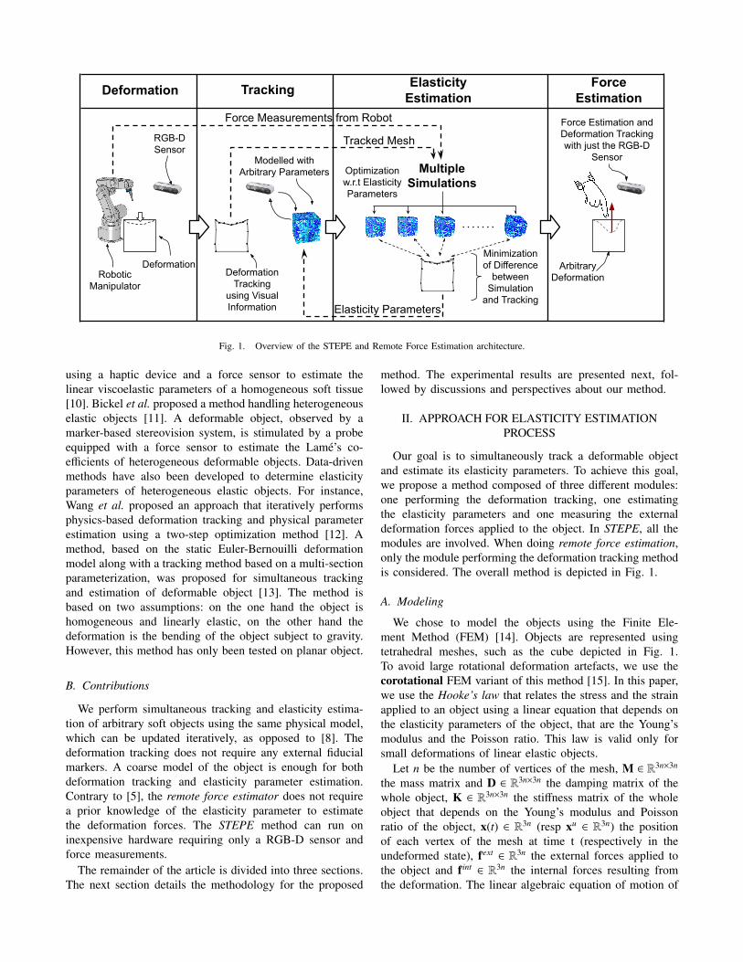
Fig. 1. Overview of the STEPE and Remote Force Estimation architecture.
using a haptic device and a force sensor to estimate thelinear viscoelastic parameters of a homogeneous soft tissue[10]. Bickel et al. proposed a method handling heterogeneouselastic objects [11]. A deformable object, observed by amarker-based stereovision system, is stimulated by a probeequipped with a force sensor to estimate the Lame’s co-efficients of heterogeneous deformable objects. Data-drivenmethods have also been developed to determine elasticityparameters of heterogeneous elastic objects. For instance,Wang et al. proposed an approach that iteratively performsphysics-based deformation tracking and physical parameterestimation using a two-step optimization method [12]. Amethod, based on the static Euler-Bernouilli deformationmodel along with a tracking method based on a multi-sectionparameterization, was proposed for simultaneous trackingand estimation of deformable object [13]. The method isbased on two assumptions: on the one hand the object ishomogeneous and linearly elastic, on the other hand thedeformation is the bending of the object subject to gravity.However, this method has only been tested on planar object.
B. Contributions
We perform simultaneous tracking and elasticity estima-tion of arbitrary soft objects using the same physical model,which can be updated iteratively, as opposed to [8]. Thedeformation tracking does not require any external fiducialmarkers. A coarse model of the object is enough for bothdeformation tracking and elasticity parameter estimation.Contrary to [5], the remote force estimator does not requirea prior knowledge of the elasticity parameter to estimatethe deformation forces. The STEPE method can run oninexpensive hardware requiring only a RGB-D sensor andforce measurements.
The remainder of the article is divided into three sections.The next section details the methodology for the proposed
method. The experimental results are presented next, fol-lowed by discussions and perspectives about our method.
II. APPROACH FOR ELASTICITY ESTIMATIONPROCESS
Our goal is to simultaneously track a deformable objectand estimate its elasticity parameters. To achieve this goal,we propose a method composed of three different modules:one performing the deformation tracking, one estimatingthe elasticity parameters and one measuring the externaldeformation forces applied to the object. In STEPE, all themodules are involved. When doing remote force estimation,only the module performing the deformation tracking methodis considered. The overall method is depicted in Fig. 1.
A. Modeling
We chose to model the objects using the Finite Ele-ment Method (FEM) [14]. Objects are represented usingtetrahedral meshes, such as the cube depicted in Fig. 1.To avoid large rotational deformation artefacts, we use thecorotational FEM variant of this method [15]. In this paper,we use the Hooke’s law that relates the stress and the strainapplied to an object using a linear equation that depends onthe elasticity parameters of the object, that are the Young’smodulus and the Poisson ratio. This law is valid only forsmall deformations of linear elastic objects.
Let n be the number of vertices of the mesh, M ∈ R3n×3n
the mass matrix and D ∈ R3n×3n the damping matrix of thewhole object, K ∈ R3n×3n the stiffness matrix of the wholeobject that depends on the Young’s modulus and Poissonratio of the object, x(t) ∈ R3n (resp xu ∈ R3n) the positionof each vertex of the mesh at time t (respectively in theundeformed state), fext ∈ R3n the external forces applied tothe object and fint ∈ R3n the internal forces resulting fromthe deformation. The linear algebraic equation of motion of
an object is given by:
Md2
dt2
(x(t)−xu)+D
ddt
(x(t)−xu)+K(x(t)−xu) = fext +fint (1)
This equation is used both to estimate the elasticity pa-rameters from deformation observations and to estimate theexternal deformation forces from deformation observationswhen the elasticity parameters converged.
B. STEPE
1) External measurements module: The external measure-ments module is in charge of measuring the deformationforces that are applied to the object. To ensure repeatabilityof experiments, we decided to use a robot equipped with aforce sensor both to deform the object and to measure theresulting forces. The end-effector deforms the object whilerecording the forces that are exerted. The end-effector motionis stopped at one point in order to maintain a static deformedstate. The module stores the external force measurements andtimestamps at which they were acquired to transmit themto the estimation algorithm when a steady-state has beenreached in the deformation tracking.
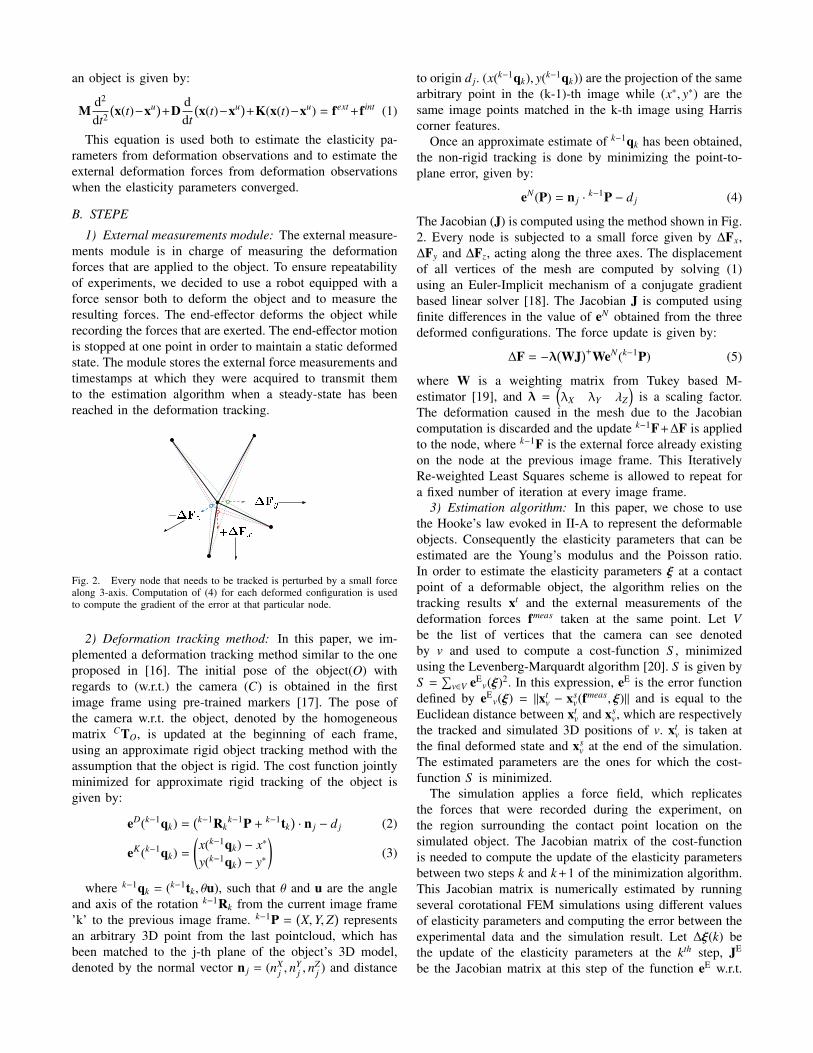
Fig. 2. Every node that needs to be tracked is perturbed by a small forcealong 3-axis. Computation of (4) for each deformed configuration is usedto compute the gradient of the error at that particular node.
2) Deformation tracking method: In this paper, we im-plemented a deformation tracking method similar to the oneproposed in [16]. The initial pose of the object(O) withregards to (w.r.t.) the camera (C) is obtained in the firstimage frame using pre-trained markers [17]. The pose ofthe camera w.r.t. the object, denoted by the homogeneousmatrix CTO, is updated at the beginning of each frame,using an approximate rigid object tracking method with theassumption that the object is rigid. The cost function jointlyminimized for approximate rigid tracking of the object isgiven by:
eD(k−1qk) =(k−1Rk
k−1P + k−1tk)· n j − d j (2)
eK(k−1qk) =
(x(k−1qk) − x∗
y(k−1qk) − y∗
)(3)
where k−1qk = (k−1tk, θu), such that θ and u are the angleand axis of the rotation k−1Rk from the current image frame’k’ to the previous image frame. k−1P =
(X,Y,Z
)represents
an arbitrary 3D point from the last pointcloud, which hasbeen matched to the j-th plane of the object’s 3D model,denoted by the normal vector n j = (nX
j , nYj , n
Zj ) and distance
to origin d j. (x(k−1qk), y(k−1qk)) are the projection of the samearbitrary point in the (k-1)-th image while (x∗, y∗) are thesame image points matched in the k-th image using Harriscorner features.
Once an approximate estimate of k−1qk has been obtained,the non-rigid tracking is done by minimizing the point-to-plane error, given by:
eN(P) = n j ·k−1P − d j (4)
The Jacobian (J) is computed using the method shown in Fig.2. Every node is subjected to a small force given by ∆Fx,∆Fy and ∆Fz, acting along the three axes. The displacementof all vertices of the mesh are computed by solving (1)using an Euler-Implicit mechanism of a conjugate gradientbased linear solver [18]. The Jacobian J is computed usingfinite differences in the value of eN obtained from the threedeformed configurations. The force update is given by:
∆F = −λ(WJ
)+WeN(k−1P) (5)
where W is a weighting matrix from Tukey based M-estimator [19], and λ =
(λX λY λZ
)is a scaling factor.
The deformation caused in the mesh due to the Jacobiancomputation is discarded and the update k−1F+∆F is appliedto the node, where k−1F is the external force already existingon the node at the previous image frame. This IterativelyRe-weighted Least Squares scheme is allowed to repeat fora fixed number of iteration at every image frame.
3) Estimation algorithm: In this paper, we chose to usethe Hooke’s law evoked in II-A to represent the deformableobjects. Consequently the elasticity parameters that can beestimated are the Young’s modulus and the Poisson ratio.In order to estimate the elasticity parameters ξ at a contactpoint of a deformable object, the algorithm relies on thetracking results xt and the external measurements of thedeformation forces fmeas taken at the same point. Let Vbe the list of vertices that the camera can see denotedby v and used to compute a cost-function S , minimizedusing the Levenberg-Marquardt algorithm [20]. S is given byS =
∑v∈V eE
v(ξ)2. In this expression, eE is the error functiondefined by eE
v(ξ) = ‖xtv − xs
v(fmeas, ξ)‖ and is equal to theEuclidean distance between xt
v and xsv, which are respectively
the tracked and simulated 3D positions of v. xtv is taken at
the final deformed state and xsv at the end of the simulation.
The estimated parameters are the ones for which the cost-function S is minimized.
The simulation applies a force field, which replicatesthe forces that were recorded during the experiment, onthe region surrounding the contact point location on thesimulated object. The Jacobian matrix of the cost-functionis needed to compute the update of the elasticity parametersbetween two steps k and k+1 of the minimization algorithm.This Jacobian matrix is numerically estimated by runningseveral corotational FEM simulations using different valuesof elasticity parameters and computing the error between theexperimental data and the simulation result. Let ∆ξ(k) bethe update of the elasticity parameters at the kth step, JE
be the Jacobian matrix at this step of the function eE w.r.t.
the elasticity parameters ξ and µ be a damping factor thatis adjusted at each Levenberg-Marquardt step. The updateof the elasticity parameters can be computed by solving for∆ξ(k) the linear equation:
∆ξ(k) =((JE)>JE + µdiag
((JE)>JE))−1(
(JE)>eE)
(6)
ξ(k + 1) = ξ(k) − ∆ξ(k) (7)
In this paper, we focus on estimating the Young’s modulus E.The Poisson ratio is assumed to be known a priori. Thus, theelasticity parameters vector is given by ξ = (E) ∈ R. At thisstage, the method permits to estimate the Young’s modulusE of a deformable object from deformation observations andexternal force measurements.
C. Remote force estimation
When doing remote force estimation, the deformationtracking module can be used without external force sensor.Let A be the set of vertices representing the active regionof the object. The active region is an approximation of thesurface of the model where the deformation is happening.This region is determined using some practical heuristicse.g., neither the vertices lying on the ground plane nor thevertices not visible from the camera are taken into account.Active vertices, denoted by a, are the vertices belonging tothe active region. The method is able to estimate the externaldeformation forces, given by fext =
∑a fext
a , which are appliedto the object in the active region, as shown in Fig. 3.
The estimated forces are projected onto the normal ofthe active surface nA =
∑a na
‖∑
a na‖because the tracking method
cannot have information about tangential forces, since (4) is apoint-to-plane distance. This produces the following estimateof the magnitude of the deformation forces: ‖fext‖ ≈ fext ·nA.
Fig. 3. Force estimation in the active region.
III. EXPERIMENTS
A. Experimental setup
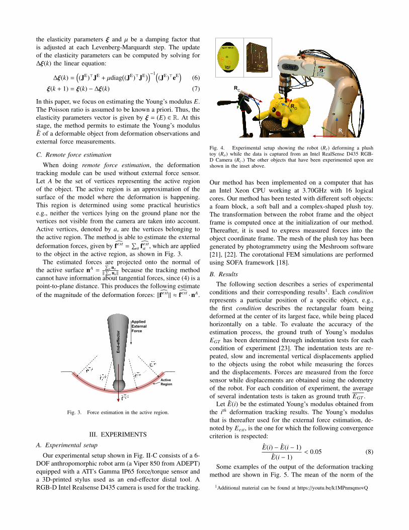
Our experimental setup shown in Fig. II-C consists of a 6-DOF anthropomorphic robot arm (a Viper 850 from ADEPT)equipped with a ATI’s Gamma IP65 force/torque sensor anda 3D-printed stylus used as an end-effector distal tool. ARGB-D Intel Realsense D435 camera is used for the tracking.
Fig. 4. Experimental setup showing the robot (Rr) deforming a plushtoy (Ro) while the data is captured from an Intel RealSense D435 RGB-D Camera (Rc.) The other objects that have been experimented upon areshown in the inset above.
Our method has been implemented on a computer that hasan Intel Xeon CPU working at 3.70GHz with 16 logicalcores. Our method has been tested with different soft objects:a foam block, a soft ball and a complex-shaped plush toy.The transformation between the robot frame and the objectframe is computed once at the initialization of our method.Thereafter, it is used to express measured forces into theobject coordinate frame. The mesh of the plush toy has beengenerated by photogrammetry using the Meshroom software[21], [22]. The corotational FEM simulations are performedusing SOFA framework [18].
B. Results
The following section describes a series of experimentalconditions and their corresponding results1. Each conditionrepresents a particular position of a specific object, e.g.,the first condition describes the rectangular foam beingdeformed at the center of its largest face, while being placedhorizontally on a table. To evaluate the accuracy of theestimation process, the ground truth of Young’s modulusEGT has been determined through indentation tests for eachcondition of experiment [23]. The indentation tests are re-peated, slow and incremental vertical displacements appliedto the objects using the robot while measuring the forcesand the displacements. Forces are measured from the forcesensor while displacements are obtained using the odometryof the robot. For each condition of experiment, the averageof several indentation tests is taken as ground truth EGT .
Let E(i) be the estimated Young’s modulus obtained fromthe ith deformation tracking results. The Young’s modulusthat is thereafter used for the external force estimation, de-noted by Eest, is the one for which the following convergencecriterion is respected:
E(i) − E(i − 1)E(i − 1)
< 0.05 (8)
Some examples of the output of the deformation trackingmethod are shown in Fig. 5. The mean of the norm of the
1Additional material can be found at https://youtu.be/k1MPnmqmovQ

Fig. 5. Tracking of the objects for estimating their elasticity parameters. The first and the fourth columns show the color image, the second and the fifthcolumns show the tracked object model and the third and the sixth columns show the value of eN , color-coded and augmented on the object
error (‖eN‖) was found to be 1.53 mm, 0.51 mm and 0.21 mmfor the foam block, soft ball and plush toy, while the standarddeviations were 7.2 mm, 0.7 mm and 1.4 mm respectively,across all the experiments reported in this article. In thethree example sequences shown in Fig. 5, the mean of thenorm of error varied between a maximum of 0.381 mm (forthe plush toy, deformed by its nose) to as low as 3 µm(for the undeformed sponge block), despite having outlyingcorrespondence or noise in the range of -5.5 cm to +9.0 cm(which gets rejected by the M-estimator). In the experimentsshown in Table I, the time required for tracking variesbetween 1.21 to 3.1 sec/frame. However, it was possible torun the same algorithm on the foam block at ∼ 800 ms/framewithout using any GPU based computation, with negligibleloss of accuracy (< 10%).
Our method can be evaluated on different criteria. Thefirst set of experiments was conducted to evaluate the time-performance of the tracking and the quality of the Young’s
modulus estimation w.r.t. the number of vertices of both thevisual mesh and the mechanical mesh. The results of thisset of experiments are grouped in Table I. In this table,#Visual designates the number of vertices of the visual meshwhile #Mechanical designates the number of vertices of themechanical mesh. ttr is the average deformation trackingtime, std(ttr) is its standard deviation, tst is the time that wasrequired to deform the object and reach a steady-state and test
is the time to estimate the Young’s modulus. All the times areexpressed in seconds. EGT and Eest correspond to the averageground truth of Young’s modulus and estimated Young’smodulus respectively, both expressed in kilo Pascals. Finally,Error designates the percentage of error of the estimation andis given by Error = 100 ∗ abs(EGT − Eest)/EGT where absdesignates the absolute value.
The second set of experiments, whose results are groupedin Table II, was conducted to evaluate the consistency of theYoung’s modulus estimation w.r.t. the initial estimate E0.
TABLE IEvaluation of tracking and estimation times and Young’s modulus (in kPa) estimation accuracy w.r.t. different quality of visual and mechanical meshes.
Objects #Visual #Mechanical ttr (s) std(ttr) (s) tst (s) test (s) EGT Eest Error (%)
foam 35 1049 1.94 0.14 62 310 454 431 5.08
foam 415 1049 2.37 0.15 122 180 454 438 3.62
foam 178 554 1.21 0.02 60 180 454 497 9.47
ball 404 627 1.38 0.03 126 70 156 136 12.8
ball 404 1060 1.61 0.02 118 96 156 149 5.0
ball 404 1954 3.09 0.07 130 330 156 148 5.1
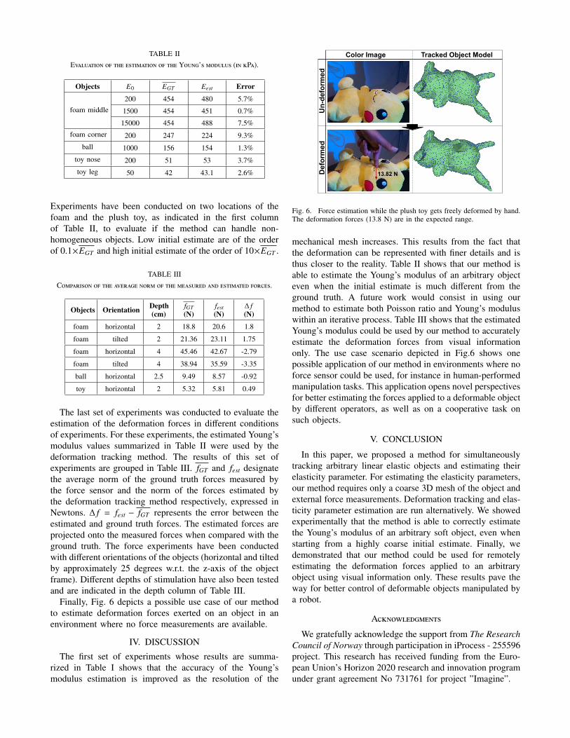
TABLE IIEvaluation of the estimation of the Young’s modulus (in kPa).
Objects E0 EGT Eest Error
foam middle200 454 480 5.7%
1500 454 451 0.7%
15000 454 488 7.5%
foam corner 200 247 224 9.3%
ball 1000 156 154 1.3%
toy nose 200 51 53 3.7%
toy leg 50 42 43.1 2.6%
Experiments have been conducted on two locations of thefoam and the plush toy, as indicated in the first columnof Table II, to evaluate if the method can handle non-homogeneous objects. Low initial estimate are of the orderof 0.1×EGT and high initial estimate of the order of 10×EGT .
TABLE IIIComparison of the average norm of the measured and estimated forces.
Objects Orientation Depth(cm)
fGT(N)
fest(N)
∆ f(N)
foam horizontal 2 18.8 20.6 1.8
foam tilted 2 21.36 23.11 1.75
foam horizontal 4 45.46 42.67 -2.79
foam tilted 4 38.94 35.59 -3.35
ball horizontal 2.5 9.49 8.57 -0.92
toy horizontal 2 5.32 5.81 0.49
The last set of experiments was conducted to evaluate theestimation of the deformation forces in different conditionsof experiments. For these experiments, the estimated Young’smodulus values summarized in Table II were used by thedeformation tracking method. The results of this set ofexperiments are grouped in Table III. fGT and fest designatethe average norm of the ground truth forces measured bythe force sensor and the norm of the forces estimated bythe deformation tracking method respectively, expressed inNewtons. ∆ f = fest − fGT represents the error between theestimated and ground truth forces. The estimated forces areprojected onto the measured forces when compared with theground truth. The force experiments have been conductedwith different orientations of the objects (horizontal and tiltedby approximately 25 degrees w.r.t. the z-axis of the objectframe). Different depths of stimulation have also been testedand are indicated in the depth column of Table III.
Finally, Fig. 6 depicts a possible use case of our methodto estimate deformation forces exerted on an object in anenvironment where no force measurements are available.
IV. DISCUSSION
The first set of experiments whose results are summa-rized in Table I shows that the accuracy of the Young’smodulus estimation is improved as the resolution of the
Fig. 6. Force estimation while the plush toy gets freely deformed by hand.The deformation forces (13.8 N) are in the expected range.
mechanical mesh increases. This results from the fact thatthe deformation can be represented with finer details and isthus closer to the reality. Table II shows that our method isable to estimate the Young’s modulus of an arbitrary objecteven when the initial estimate is much different from theground truth. A future work would consist in using ourmethod to estimate both Poisson ratio and Young’s moduluswithin an iterative process. Table III shows that the estimatedYoung’s modulus could be used by our method to accuratelyestimate the deformation forces from visual informationonly. The use case scenario depicted in Fig.6 shows onepossible application of our method in environments where noforce sensor could be used, for instance in human-performedmanipulation tasks. This application opens novel perspectivesfor better estimating the forces applied to a deformable objectby different operators, as well as on a cooperative task onsuch objects.
V. CONCLUSION
In this paper, we proposed a method for simultaneouslytracking arbitrary linear elastic objects and estimating theirelasticity parameter. For estimating the elasticity parameters,our method requires only a coarse 3D mesh of the object andexternal force measurements. Deformation tracking and elas-ticity parameter estimation are run alternatively. We showedexperimentally that the method is able to correctly estimatethe Young’s modulus of an arbitrary soft object, even whenstarting from a highly coarse initial estimate. Finally, wedemonstrated that our method could be used for remotelyestimating the deformation forces applied to an arbitraryobject using visual information only. These results pave theway for better control of deformable objects manipulated bya robot.
Acknowledgments
We gratefully acknowledge the support from The ResearchCouncil of Norway through participation in iProcess - 255596project. This research has received funding from the Euro-pean Union’s Horizon 2020 research and innovation programunder grant agreement No 731761 for project ”Imagine”.
References
[1] R. A. Newcombe, D. Fox, and S. M. Seitz, “Dynamicfusion: Recon-struction and tracking of non-rigid scenes in real-time,” in Proceedingsof the IEEE Conference on Computer Vision and Pattern Recognition,2015, pp. 343–352.
[2] M. Innmann, M. Zollhofer, M. Nießner, C. Theobalt, and M. Stam-minger, “Volumedeform: Real-time volumetric non-rigid reconstruc-tion,” in Proceedings of European Conference on Computer Vision.Springer, 2016, pp. 362–379.
[3] S. Bronte, L. Bergasa, D. Pizarro, and R. Barea, “Model-based real-time non-rigid tracking,” Sensors, vol. 17, no. 10, p. 2342, 2017.
[4] S. Bronte, M. Paladini, L. M. Bergasa, L. Agapito, and R. Arroyo,“Real-time sequential model-based non-rigid sfm,” in Proceedings ofthe IEEE Conference on Intelligent Robots and Systems, 2014, pp.1026–1031.
[5] Z. Zhang, A. Petit, J. Dequidt, and C. Duriez, “Calibration and externalforce sensing for soft robots using an rgb-d camera,” IEEE Roboticsand Automation Letters, vol. 4, no. 3, pp. 2356–2363, 2019.
[6] A. Petit, S. Cotin, V. Lippiello, and B. Siciliano, “Capturing deforma-tions of interacting non-rigid objects using rgb-d data,” in Proceedingsof the IEEE Conference on Intelligent Robots and Systems, 2018, pp.491–497.
[7] A. Varol, M. Salzmann, P. Fua, and R. Urtasun, “A constrained latentvariable model,” in Proceedings of the IEEE Conference on ComputerVision and Pattern Recognition. Ieee, 2012, pp. 2248–2255.
[8] B. Frank, R. Schmedding, C. Stachniss, M. Teschner, and W. Burgard,“Learning the elasticity parameters of deformable objects with amanipulation robot,” in Proceedings of the IEEE Conference onIntelligent Robots and Systems, 2010, pp. 1877–1883.
[9] P. J. Besl and N. D. McKay, “Method for registration of 3-d shapes,”in Sensor fusion IV: control paradigms and data structures, vol. 1611.International Society for Optics and Photonics, 1992, pp. 586–606.
[10] M. Sedef, E. Samur, and C. Basdogan, “Real-time finite-elementsimulation of linear viscoelastic tissue behavior based on experimentaldata,” IEEE Computer Graphics and Applications, vol. 26, no. 6, 2006.
[11] B. Bickel, M. Bacher, M. A. Otaduy, W. Matusik, H. Pfister, andM. Gross, “Capture and modeling of non-linear heterogeneous softtissue,” in Proceedings of the ACM Conference of Transactions onGraphics, vol. 28. ACM, 2009, p. 89.
[12] B. Wang, L. Wu, K. Yin, U. Ascher, L. Liu, and H. Huang, “Defor-mation Capture and Modeling of Soft Objects,” ACM Transaction onGraphique, vol. 34, no. 4, pp. 94:1–94:12, 2015.
[13] A. R. Fugl, A. Jordt, H. G. Petersen, M. Willatzen, and R. Koch, “Si-multaneous estimation of material properties and pose for deformableobjects from depth and color images,” in Proceedings of Joint GermanAssociation for Pattern Recognition and OAGM Symposium. Springer,2012, pp. 165–174.
[14] A. Nealen, M. Muller, R. Keiser, E. Boxerman, and M. Carlson,“Physically based deformable models in computer graphics,” Com-puter Graphics Forum, vol. Vol 25, pp. 809–836, 2006.
[15] M. Muller and M. Gross, “Interactive virtual materials,” in Proceedingsof Graphics interface. Canadian Human-Computer CommunicationsSociety, 2004, pp. 239–246.
[16] A. Sengupta, A. Krupa, and E. Marchand, “Tracking of non-rigidobjects using rgb-d camera,” in Proceedings of the IEEE InternationalConference on Systems, Man, and Cybernetics, 2019.
[17] E. Marchand, H. Uchiyama, and F. Spindler, “Pose estimation for aug-mented reality: a hands-on survey,” IEEE transactions on visualizationand computer graphics, vol. 22, no. 12, pp. 2633–2651, 2015.
[18] F. Faure, C. Duriez, H. Delingette, J. Allard, B. Gilles, S. Marchesseau,H. Talbot, H. Courtecuisse, G. Bousquet, I. Peterlik, and S. Cotin,“SOFA: A Multi-Model Framework for Interactive Physical Simula-tion,” in Soft Tissue Biomechanical Modeling for Computer AssistedSurgery, ser. Studies in Mechanobiology, Tissue Engineering andBiomaterials. Springer, 2012, vol. 11, pp. 283–321.
[19] P. Meer, D. Mintz, A. Rosenfeld, and D. Y. Kim, “Robust regressionmethods for computer vision: A review,” International journal ofcomputer vision, vol. 6, no. 1, pp. 59–70, 1991.
[20] J. J. More, “The levenberg-marquardt algorithm: implementation andtheory,” in Numerical analysis. Springer, 1978, pp. 105–116.
[21] P. Moulon, P. Monasse, and R. Marlet, “Adaptive structure frommotion with a contrario model estimation,” in Proceedings of the AsianComputer Vision Conference. Springer Berlin Heidelberg, 2012, pp.257–270.
[22] M. Jancosek and T. Pajdla, “Multi-view reconstruction preservingweakly-supported surfaces,” in Proceedings of IEEE Conference onComputer Vision and Pattern Recognition, 2011.
[23] C. T. McKee, J. A. Last, P. Russell, and C. J. Murphy, “Indentationversus tensile measurements of young’s modulus for soft biologicaltissues,” Tissue Engineering Part B: Reviews, vol. 17, no. 3, pp. 155–164, 2011.