Simulink ® Interface Course 13 Active-HDL Interfaces.
24
Simulink ® Interface Course 13 Active-HDL Interfaces
-
Upload
annis-garrison -
Category
Documents
-
view
274 -
download
3
Transcript of Simulink ® Interface Course 13 Active-HDL Interfaces.
Simulink® InterfaceSimulink® Interface
Course 13
Active-HDL Interfaces
All materials updated on: September 30, 2005
OverviewOverviewOverviewOverview
The MathWorks' MATLAB®/Simulink® simulation environment provides a powerful high level mathematical modeling environment for DSP systems that can be widely used for algorithm development and verification.
Active-HDL provides an interface to MATLAB and Simulink simulation environment, which allows co-simulation of functional blocks described by using mathematical formulas and behavioral models described by using hardware description languages.
The Simulink Interface provides users with the following benefits:
– Intuitive interface that fills the gap between HDL simulation and high level mathematical modeling environment for DSP systems
– Displaying simulation results in both the Simulink environment and the Active-HDL waveform window
– Automatic value conversion between Active-HDL and Simulink– Advanced testbenches employing complex mathematical formulas used to stimulate unit
under test– Integration with Xilinx System Generator™
All materials updated on: September 30, 2005
13.1 Interface Setup13.1 Interface Setup
The interface delivered with the Active-HDL installation program allows you to select a Verilog module, EDIF cell or VHDL entity/architecture pair that will be used as a black-box during the verification process performed within Simulink.
Before the first use of the Simulink Interface, you need to install the Active-HDL Blockset delivered with the Active-HDL installation.
Provided setup script automates the installation process.
Since Active-HDL will be initialized during the co-simulation by Simulink, you need to modify the $PATH variable to point to the /Bin subdirectory of the Active-HDL installation.
All materials updated on: September 30, 2005
13.1a Installing Active-HDL Blockset13.1a Installing Active-HDL Blockset
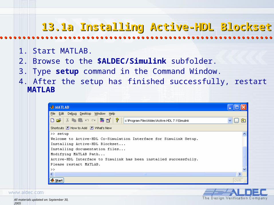
1. Start MATLAB.2. Browse to the $ALDEC/Simulink subfolder.3. Type setup command in the Command Window. 4. After the setup has finished successfully, restart MATLAB
All materials updated on: September 30, 2005
13.2 Generating Block Description for Simulink
13.2 Generating Block Description for Simulink
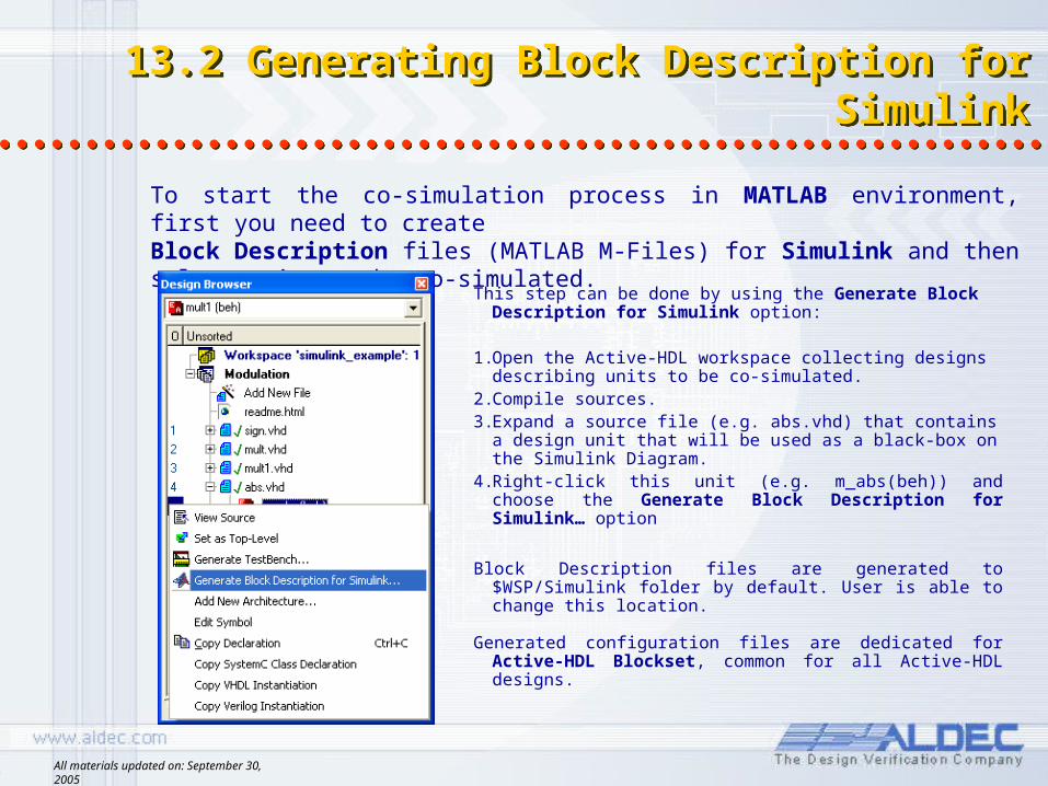
This step can be done by using the Generate Block Description for Simulink option:
1.Open the Active-HDL workspace collecting designs describing units to be co-simulated.
2.Compile sources.3.Expand a source file (e.g. abs.vhd) that contains a
design unit that will be used as a black-box on the Simulink Diagram.
4.Right-click this unit (e.g. m_abs(beh)) and choose the Generate Block Description for Simulink… option
Block Description files are generated to $WSP/Simulink folder by default. User is able to change this location.
Generated configuration files are dedicated for Active-HDL Blockset, common for all Active-HDL designs.
To start the co-simulation process in MATLAB environment, first you need to createBlock Description files (MATLAB M-Files) for Simulink and then select units to be co-simulated.
All materials updated on: September 30, 2005
13.3 Using Active-HDL Blockset 13.3 Using Active-HDL Blockset
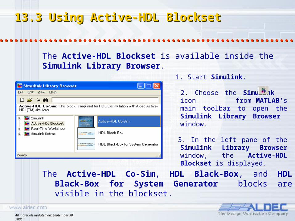
1. Start Simulink.
2. Choose the Simulink icon from MATLAB's main toolbar to open the Simulink Library Browser window.
3. In the left pane of the Simulink Library Browser window, the Active-HDL Blockset is displayed.
The Active-HDL Blockset is available inside the Simulink Library Browser.
The Active-HDL Co-Sim, HDL Black-Box, and HDL Black-Box for System Generator blocks are visible in the blockset.
All materials updated on: September 30, 2005
13.4 Using Active-HDL Blockset- blocks
13.4 Using Active-HDL Blockset- blocks
Following blocks are provided: 1. Active-HDL Co-Sim 2. HDL Black-Box, 3. HDL Black-Box for System Generator
in the Active-HDL Blockset and other MATLAB simulation libraries to create his own simulation model.
Before co-simulation can be started, the Active-HDL Co-Sim block needs to be added to the model window.
This block is required to successfully initialize the simulation process and it can be used to define parameters of the co-simulation session.
The black-boxes generated by the Generate Block Description for Simulink… can be simulated after their parameters are setup.
All materials updated on: September 30, 2005
13.5 Using Active-HDL Blockset- configuring Active-HDL Co-Sim block
13.5 Using Active-HDL Blockset- configuring Active-HDL Co-Sim block
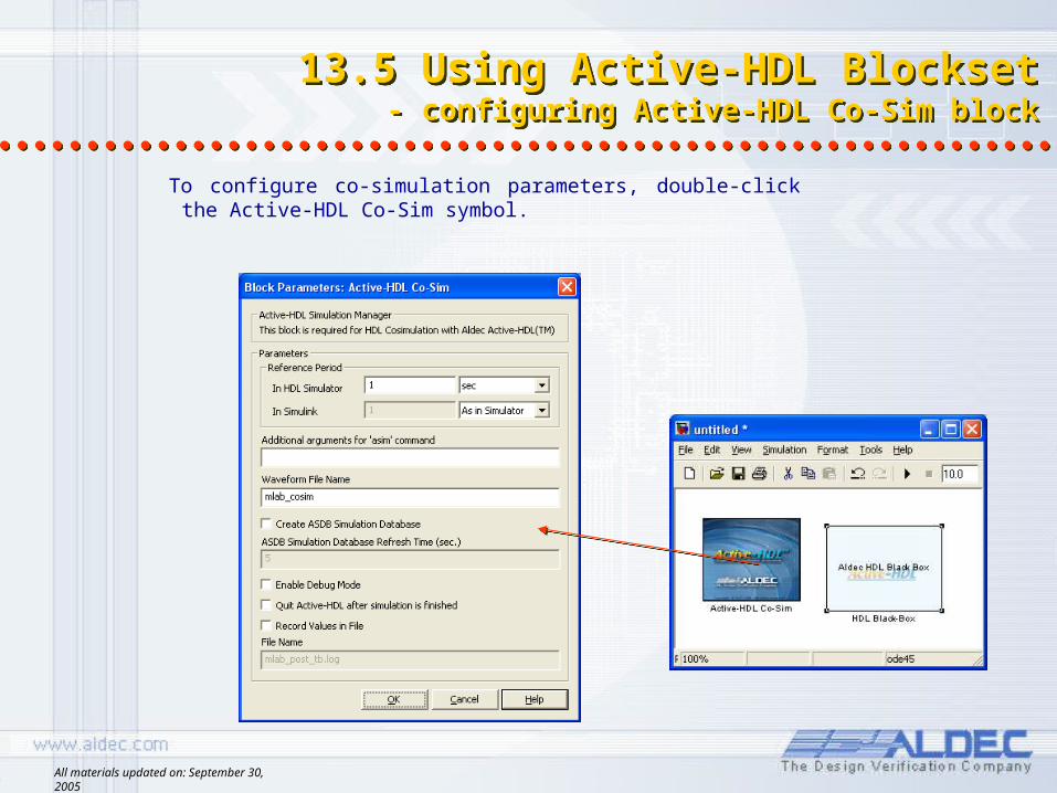
To configure co-simulation parameters, double-click the Active-HDL Co-Sim symbol.
All materials updated on: September 30, 2005
13.6 Using Active-HDL Blockset - configuring Active-HDL Co-Sim block
13.6 Using Active-HDL Blockset - configuring Active-HDL Co-Sim block
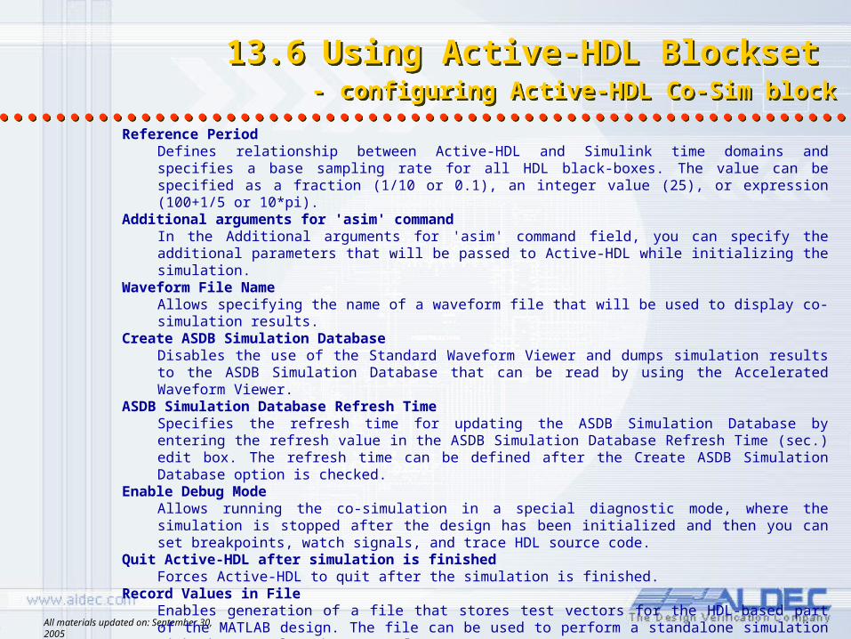
Reference PeriodDefines relationship between Active-HDL and Simulink time domains and specifies a base sampling rate for all HDL black-boxes. The value can be specified as a fraction (1/10 or 0.1), an integer value (25), or expression (100+1/5 or 10*pi).
Additional arguments for 'asim' commandIn the Additional arguments for 'asim' command field, you can specify the additional parameters that will be passed to Active-HDL while initializing the simulation.
Waveform File NameAllows specifying the name of a waveform file that will be used to display co-simulation results.
Create ASDB Simulation DatabaseDisables the use of the Standard Waveform Viewer and dumps simulation results to the ASDB Simulation Database that can be read by using the Accelerated Waveform Viewer.
ASDB Simulation Database Refresh TimeSpecifies the refresh time for updating the ASDB Simulation Database by entering the refresh value in the ASDB Simulation Database Refresh Time (sec.) edit box. The refresh time can be defined after the Create ASDB Simulation Database option is checked.
Enable Debug ModeAllows running the co-simulation in a special diagnostic mode, where the simulation is stopped after the design has been initialized and then you can set breakpoints, watch signals, and trace HDL source code.
Quit Active-HDL after simulation is finishedForces Active-HDL to quit after the simulation is finished.
Record Values in FileEnables generation of a file that stores test vectors for the HDL-based part of the MATLAB design. The file can be used to perform a standalone simulation with the use of Active-HDL only.
File Name The name of the file that stores data for a standalone simulation. It can be specified after the
Record Values in File option is checked.

All materials updated on: September 30, 2005
13.7 Using Active-HDL Blockset- selecting black box configuration
13.7 Using Active-HDL Blockset- selecting black box configuration
To associate HDL Black-Box with an HDL unit, double-click the symbol and select the block description file generated for this unit.
NOTE:The Select HDL Black-Box Configuration dialog box lists all configuration files placed in the current working folder. However, you can specify any configuration file visible in the MATLAB path.
All materials updated on: September 30, 2005
13.8 Using Active-HDL Blockset - interface signals customization
13.8 Using Active-HDL Blockset - interface signals customization
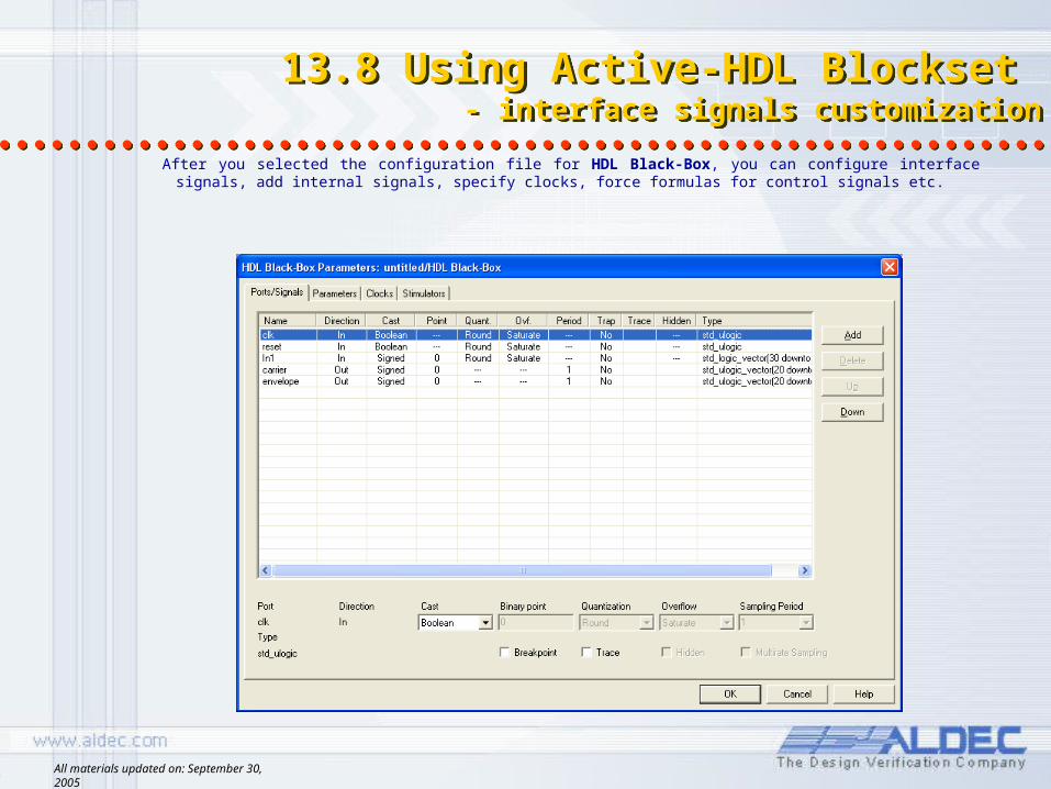
After you selected the configuration file for HDL Black-Box, you can configure interface signals, add internal signals, specify clocks, force formulas for control signals etc.

All materials updated on: September 30, 2005
13.9 Using Active-HDL Blockset - interface signals customization
13.9 Using Active-HDL Blockset - interface signals customization
PortsLists all ports of the simulated unit. Also displays internal signals added to black-box interface.
DirectionDisplays the direction of port (In, Out). For ports selected in either Clocks or Stimulator tabs, displays the special function of such ports: Clock, Sync, Custom. Internal signals are indicated as Internal.
CastSpecifies the numerical representation of a signal's value. Available types are:Boolean, SIGN and UNSIGN.
Binary PointSpecifies the binary point for a vector. Negative values and values greater than vector width are supported.
QuantizationSpecifies the type of quantization method (available values are: truncate, round ).
OverflowSpecifies handling method of arithmetical overflow (available values are: saturate, wrap, error).
PeriodSpecifies the sampling period of the output signal. You can specify an integer value related to Reference Period or one of signals selected as Clock or Sync. When you need to specify several sampling periods, check the Multirate Sampling option and enter required sampling periods for each output separately.
TrapSpecifies whether a breakpoint will be set on the selected signal.
TraceIf this option is checked for selected signal, then it will be added to the waveform editor during simulation.
HiddenSpecifies whether port should be visible on the block graphical representation and thus available in the Simulink diagram
TypeDisplays the type of the signal. Supported VHDL types are: BIT, BIT_VECTOR, STD_ULOGIC, STD_ULOGIC_VECTOR, STD_LOGIC, STD_LOGIC_VECTOR.
All materials updated on: September 30, 2005
13.10 Co-Simulation - Simulink simulation Model 13.10 Co-Simulation - Simulink simulation Model
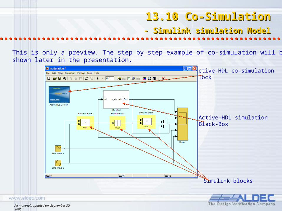
Active-HDL simulation Black-Box
Simulink blocks
Active-HDL co-simulation block
This is only a preview. The step by step example of co-simulation will be shown later in the presentation.
All materials updated on: September 30, 2005
13.11 Co-Simulation - connection to Active-HDL
13.11 Co-Simulation - connection to Active-HDL
1. All HDL Black-Boxes from the Active-HDL Blockset are simulated with Active-HDL simulator.
2. Running simulation from the Simulink diagram automatically invokes Active-HDL and configures it to run co-simulation of code associated with all instantiated black-boxes.
3. User can review results in MATLAB as well as Active-HDL waveform.
NOTE: Waveform is created in an automated way when “Trace” option has been
selected
All materials updated on: September 30, 2005
13.12 Co-Simulation - simulation start
13.12 Co-Simulation - simulation start
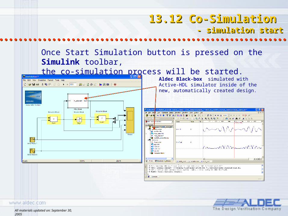
Once Start Simulation button is pressed on the Simulink toolbar, the co-simulation process will be started.
Aldec Black-box simulated with Active-HDL simulator inside of the new, automatically created design.
All materials updated on: September 30, 2005
13.13 Simulation with Simulink - view simulation results
13.13 Simulation with Simulink - view simulation results
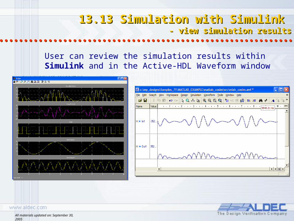
User can review the simulation results within Simulink and in the Active-HDL Waveform window
All materials updated on: September 30, 2005
13.14 Example of use – Active-HDL design
13.14 Example of use – Active-HDL design
Open simulink_example workspace.This workspace contains Modulator design.
The design contains the following resource files:1. abs.vhd VHDL equivalent model of the Simulink Abs block.2. mult.vhd, mult1.vhd VHDL equivalent model of the Simulink Product block.3. sign.vhd VHDL equivalent model of the Simulink Sign block.4. Modulation.mdl Simulink models
All materials updated on: September 30, 2005
13.15 Design Example – generating block description files
13.15 Design Example – generating block description files
1. Compile all files within design.2. Use Generate Block Description for Simulink… for
each entity in the library and assign created files to HDL Black-Box symbols on the Simulink diagram.
All materials updated on: September 30, 2005
13.16 Design Example - Simulink simulation model
13.16 Design Example - Simulink simulation model
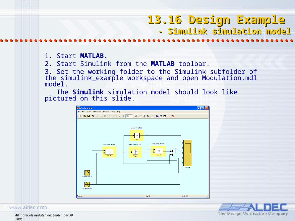
1. Start MATLAB.2. Start Simulink from the MATLAB toolbar.3. Set the working folder to the Simulink subfolder of the simulink_example workspace and open Modulation.mdl model. The Simulink simulation model should look like pictured on this slide.
All materials updated on: September 30, 2005
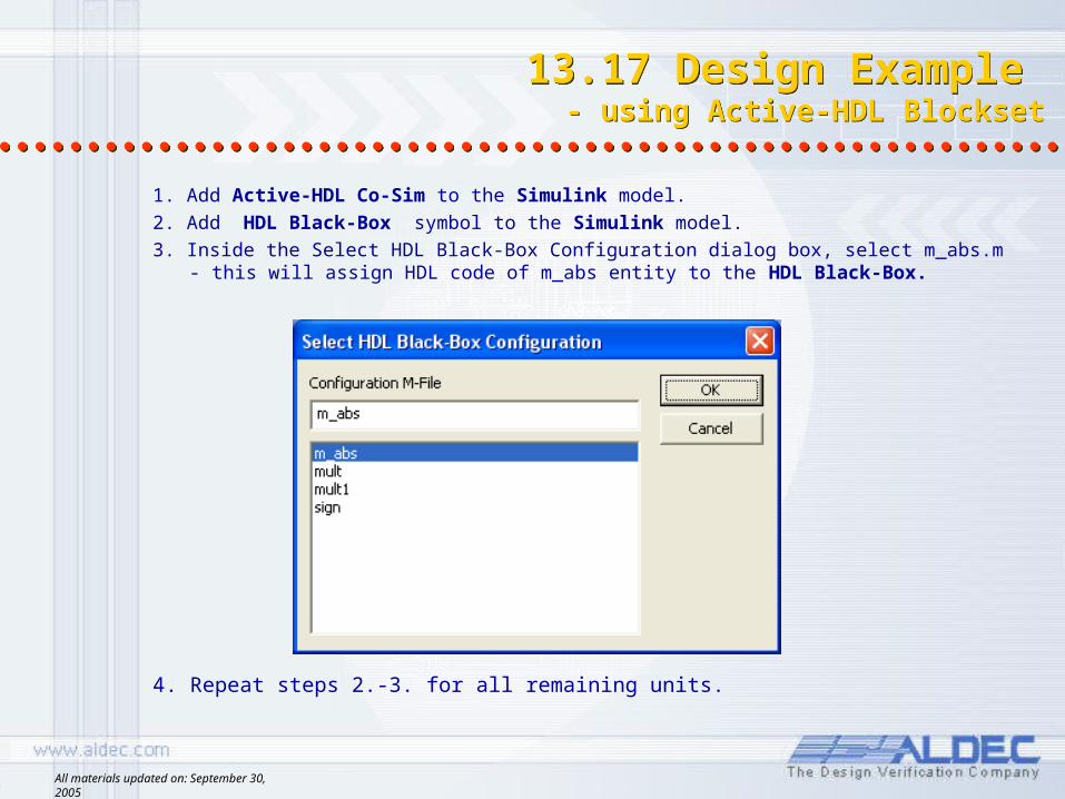
1. Add Active-HDL Co-Sim to the Simulink model.2. Add HDL Black-Box symbol to the Simulink model.3. Inside the Select HDL Black-Box Configuration dialog box, select m_abs.m - this
will assign HDL code of m_abs entity to the HDL Black-Box.
13.17 Design Example - using Active-HDL Blockset
13.17 Design Example - using Active-HDL Blockset
4. Repeat steps 2.-3. for all remaining units.
All materials updated on: September 30, 2005
13.18 Design Example- configuring blocks
13.18 Design Example- configuring blocks
Please, specify following values for all module parameters using HDL Black-Box Parameters dialog box:
For SIGN block, set:Port In1: Cast = Signed, Binary Point = 24, Quantization = Truncate, Overflow = SaturatePort Out1: Cast = Signed, Binary Point = 0
For MULT block, set:Port Sin_wav1: Cast = Unsigned, Binary Point = 9, Quantization = Truncate, Overflow = SaturatePort Sin_wav2: Cast = Signed, Binary Point = 15, Quantization = Truncate, Overflow = SaturatePort Out1: Cast = Signed, Binary Point = 24
For MULT1 block, set:Port I_abs: Cast = Unsigned, Binary Point = 24, Quantization = Truncate, Overflow = SaturatePort I_sig: Cast = Signed, Binary Point = 0, Quantization = Truncate, Overflow = SaturatePort Out1: Cast = Signed, Binary Point = 24
For M_ABS block, set:Port In1: Cast = Signed, Binary Point = 24, Quantization = Truncate, Overflow = SaturatePort Out1: Cast = Unsigned, Binary Point = 24
NOTE:Please use “Trace” option for all signals and set “Period” to 1.
Also, specify following values in the Active-HDL Co-Sim Parameters dialog box:
Reference Period:In HDL Simulator: 1/20 secIn Simulink: As In Simulator
This completes the preparation for co-simulation.
All materials updated on: September 30, 2005
13.19 Design Example - replacing blocks with HDL Black-Boxes
13.19 Design Example - replacing blocks with HDL Black-Boxes
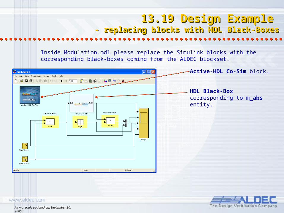
Inside Modulation.mdl please replace the Simulink blocks with the corresponding black-boxes coming from the ALDEC blockset.
Active-HDL Co-Sim block.
HDL Black-Box corresponding to m_abs entity.
All materials updated on: September 30, 2005
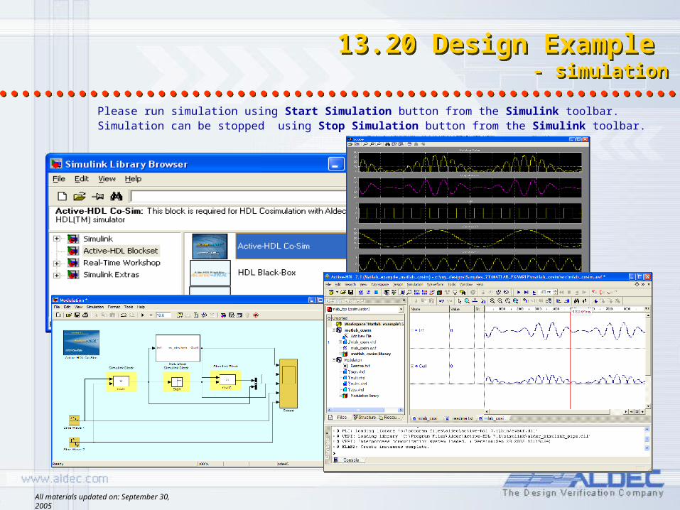
13.20 Design Example - simulation
13.20 Design Example - simulation
Please run simulation using Start Simulation button from the Simulink toolbar.Simulation can be stopped using Stop Simulation button from the Simulink toolbar.
All materials updated on: September 30, 2005
13.21 Design Example - waveform settings
13.21 Design Example - waveform settings
Active-HDL waveform can display signal values in analog shape.Please use inside the waveform signal properties to define display parameters
form_abs symbol ports.
Please set parameters:• Signal In1: Radix - decimal, Notation - Signed 2`s Complement, Display
- Analog, Height - 128• Signal Out1: Radix - decimal, Notation - Unsigned, Display - Analog,
Height - 128