

Simulcast Systems for Public Safety · Presentation8 29-Nov-11 Backround: Review of Eye Patterns...
20
Presentation1 29-Nov-11 Simulcast Systems for Public Safety Rick Taylor Senior Scientist, PSPC Lynchburg, Va 1 Dec 2011
Transcript of Simulcast Systems for Public Safety · Presentation8 29-Nov-11 Backround: Review of Eye Patterns...
Presentation1 29-Nov-11
Simulcast Systems for Public Safety
Rick TaylorSenior Scientist, PSPC
Lynchburg, Va1 Dec 2011

Presentation2
Public Safety Mission Critical Communications Systems
• Secure Wide-area Voice and Data Networking
• Interoperability and Reliability are Key• Fragmented Frequency Bands• Rapid Access - Sub-second Across Network• Mostly Group Calls (“One to Many”)• Near Ubiquitous Coverage

Presentation3
Near Ubiquitous Coverage
• Coverage Reliability Requirement is Typically 95-98% • Service Areas: From Small Towns Through Statewide• 3 Watts Portable Output Power
Portable In-Building
Portable In-Basement
Mobile
Towers Typically Spaced 2- 20 miles
30 dB Building Loss Typical
100 W Base Station Output Power + Ant Gain Typical
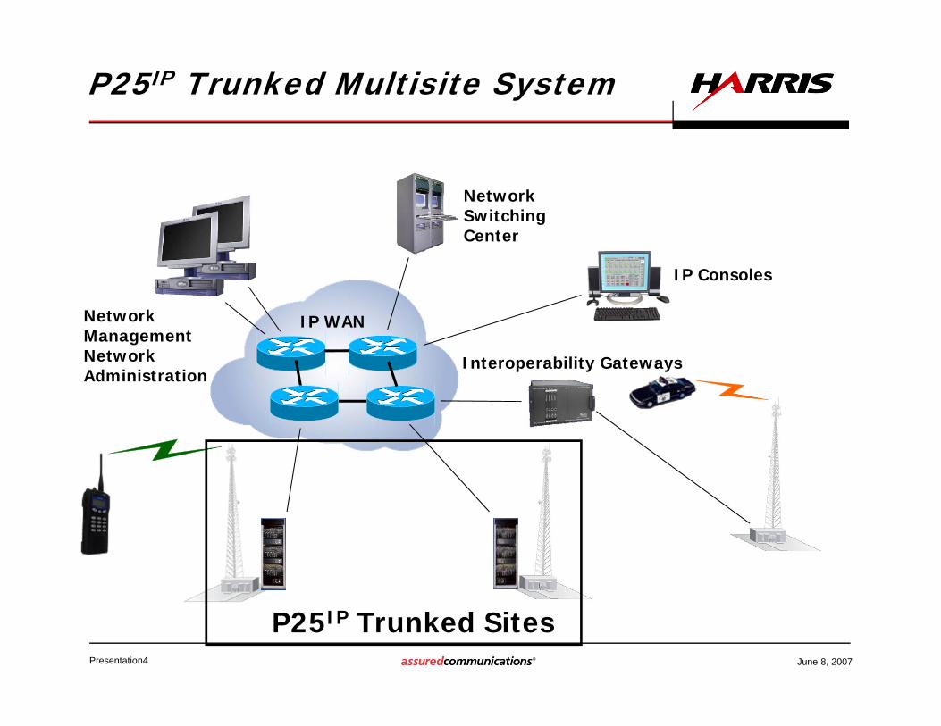
Presentation4 June 8, 2007
P25IP Trunked Sites
P25IP Trunked Multisite System
IP Consoles
IP WAN
NetworkSwitchingCenter
Network ManagementNetwork Administration
Interoperability Gateways

Presentation5 June 8, 2007
P25IP Simulcast Sites
P25IP Simulcast Systems
IP Consoles
IP WAN
NetworkSwitchingCenter
Network ManagementNetwork Administration
Interoperability Gateways
ControlPoint & Voters
• Used Since the Late 80’s Primarily in Urban Areas
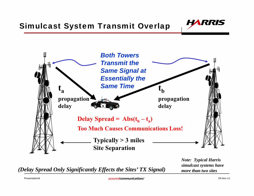
Presentation6 29-Nov-11
Simulcast System Transmit Overlap
Delay Spread = Abs(tb – ta)Too Much Causes Communications Loss!
tb propagation delay
Both Towers Transmit the Same Signal at Essentially the Same Time
Typically > 3 milesSite Separation
ta propagation delay
Note: Typical Harris simulcast systems have more than two sites(Delay Spread Only Significantly Effects the Sites’ TX Signal)
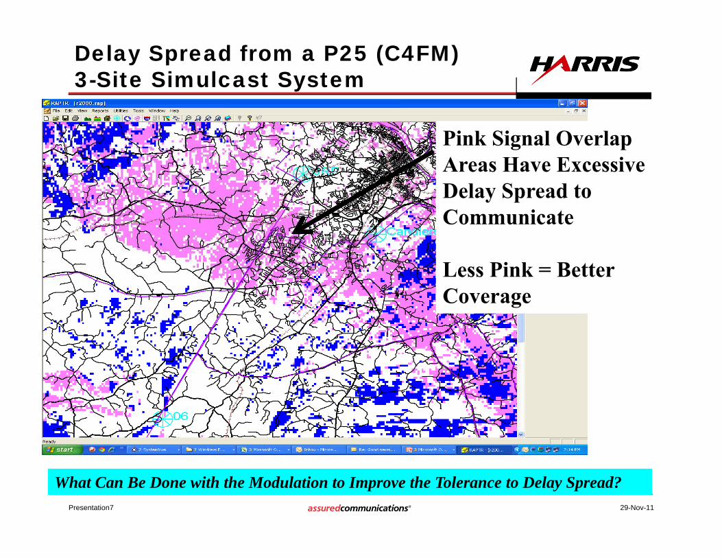
Presentation7
Delay Spread from a P25 (C4FM) 3-Site Simulcast System
29-Nov-11
Pink Signal Overlap Areas Have Excessive Delay Spread to Communicate
Less Pink = Better Coverage
What Can Be Done with the Modulation to Improve the Tolerance to Delay Spread?

Presentation8 29-Nov-11
Backround: Review of Eye Patterns
• An Overlay of Time Segments of the Demodulated Digital Signal, with Each Segment an Integer Multiple of the Bit (or Symbol) Period
EDACS Demodulated SignalSystemView
10.45e-3
10.45e-3
10.65e-3
10.65e-3
10.85e-3
10.85e-3
11.05e-3
11.05e-3
11.25e-3
11.25e-3
1
500e-3
0
-500e-3
-1
Amplitude
Time in Seconds
Extracted from w0 (Samples 1000 to 1100)
2-LEVEL EDACS DEMODULATED SIGNAL
SystemView
0
0
20e-6
20e-6
40e-6
40e-6
60e-6
60e-6
80e-6
80e-6
100e-6
100e-6
120e-6
120e-6
140e-6
140e-6
160e-6
160e-6
180e-6
180e-6
1
500e-3
0
-500e-3
-1
Ampl
itude
Time in Seconds
Sliced w0 (No Repeat, Start = 1,006, Length = 20)
Eye Pattern Showing Two Bit Periods

Presentation9 29-Nov-11
Background: Recovering the Informationfrom a 2-Level FSK Modulation
An “Open” Eye Reduces Errors in Data Recovery (i.e. Lowers Bit Error Rate)
SystemView
45e-6
45e-6
65e-6
65e-6
85e-6
85e-6
105e-6
105e-6
125e-6
125e-6
145e-6
145e-6
165e-6
165e-6
1
500e-3
0
-500e-3
-1
Eye
Threshold
Declare “1”
Declare “0”
Desired Sample Point

Presentation10 29-Nov-11
Eye Pattern of P25 Phase 1 4-Level C4FM Modulation
SystemView
0
0
100e-6
100e-6
200e-6
200e-6
300e-6
300e-6
400e-6
400e-6
500e-6
500e-6
600e-6
600e-6
4
2
0
-2
-4
Ampl
itude
Time in Seconds
Sliced w3 (No Repeat, Start = 200, Length = 60)
Desired Sample Points
0,10,0
1,0
1,1
3 Thresholds
Di-Bits Declared:
(Figure shows three symbol periods)

Presentation11 29-Nov-11
Deterioration of P25 Eye Due to Simulcast Delay Spread
Strong Signal, no Fading
SystemView
65e-6
65e-6
85e-6
85e-6
105e-6
105e-6
125e-6
125e-6
2
0
-2
-4
Am
plit
ude
Time in Seconds
Sliced w3 (No Repeat, Start = 200, Length = 20)
SystemView
85e-6
85e-6
105e-6
105e-6
125e-6
125e-6
145e-6
145e-6
2
0
-2
-4
Am
plit
ude
Time in Seconds
Sliced w3 (No Repeat, Start = 200, Length = 20)
Strong Signal, 25 usec Delay Spread Fading
Strong Signal, 50 usec Delay Spread Fading
SystemView
85e-6
85e-6
105e-6
105e-6
125e-6
125e-6
145e-6
145e-6
2
0
-2
-4
Am
plit
ude
Time in Seconds
Sliced w3 (No Repeat, Start = 200, Length = 20)

Presentation12 29-Nov-11
Model of Delay Spread’s Effect On the Eye
Wider is Better!
1st Path Eye
Delay Spread
2nd Path Eye
Path1+Path2 Usable Eye

Presentation13 29-Nov-11
Eye Patterns of Different Modulations
SystemView
0
0
100e-6
100e-6
200e-6
200e-6
300e-6
300e-6
400e-6
400e-6
500e-6
500e-6
600
600
3
2
1
0
-1
-2
-3
Am
plitu
de
Time in Seconds
Sliced w4 (No Repeat, Start = 1,000, Length = 30)SystemView
0
0
100e-6
100e-6
200e-6
200e-6
300e-6
300e-6
400e-6
400e-6
500e-6
500e-6
600
600
3
2
1
0
-1
-2
-3A
mpl
itude
Time in Seconds
Sliced w8 (No Repeat, Start = 1,000, Length = 30)SystemView
0
0
100e-6
100e-6
200e-6
200e-6
300e-6
300e-6
400e-6
400e-6
500e-6
500e-6
600
6003
2
1
0
-1
-2
-3
Am
plitu
de
Time in Seconds
Sliced w16 (No Repeat, Start = 1,000, Length = 30)
SystemView
0
0
100e-6
100e-6
200e-6
200e-6
300e-6
300e-6
400e-6
400e-6
500e-6
500e-6
600e
600e
2
1
0
-1
-2
Ampl
itude
Time in Seconds
Sliced w20 (No Repeat, Start = 1,000, Length = 30)
C4FM, α =0.2 (Present P25) CQPSK, α = 0.2 C4FM, α =1
CQPSK, α =1
SystemView
0
0
100e-6
100e-6
200e-6
200e-6
300e-6
300e-6
400e-6
400e-6
500e-6
500e-6
600e-6
600e-6
2
1
0
-1
-2
Ampl
itude
Time in Seconds
Sliced w3 (No Repeat, Start = 200, Length = 30)
Preferred Wide CQPSK
(Denoted WCQPSK)Note: α is the
filter rolloff factor

Presentation14 29-Nov-11
WCQPSK π/4 Differential Phase Modulation
Sy stemView
20.5e-3
20.5e-3
22.5e-3
22.5e-3
24.5e-3
24.5e-3
26.5e-3
26.5e-3
28.5e-3
28.5e-3
30.5e-3
30.5e-3
32.5e-3
32.5e-3
34.5e-3
34.5e-3
1
500e-3
0
-500e-3
-1
-1.5
Amplitud
e
Time in Seconds
Sink 335
Variable Envelope Modulated Signal To Linearized PA
Modulated Time Domain SigRaised Cosine
Filter (α)
Raised Cosine Filter(α)
Table Lookup
I
Q
I
Q
“Constant Envelope”
Signal To PAI, Q
Modulator4 Level Symbols
In
-3,-1,1,3
I
α is Raised Cosine Filter Rolloff Factor
CQPSK I, Q Constellation
Syst emView
-40
-40
-20
-20
0
0
20
20
40
4060
40
20
0
-20
-40
-60
w0
Am
plit
ude
w1 Am plit ude
Sink 484 vs Sink 485 (w0 vs w1)
I
Q

Presentation15 29-Nov-11
Symbol Period
Symbol Period
Our Patented WCQPSK Modulation Filter ‘s 2nd Zero Crossing Impulse Response Enables a Wider Eye
2nd Zero Crossing

Presentation16 29-Nov-11
Discernible WCQPSK Eyes Remain Even for 120 usec Delay Spread
Faded, Delay Spread=0
SystemView
0
0
100e-6
100e-6
200e-6
200e-6
300e-6
300e-6
400e-6
400e-6
500e-6
500e-6
600e-6
600e-6
20e+3
0
-20e+3
Ampl
itude
Time in Seconds
Sliced w3 (No Repeat, Start = 1,000, Length = 30)
Faded, Delay Spread=40 usec
SystemView
0
0
100e-6
100e-6
200e-6
200e-6
300e-6
300e-6
400e-6
400e-6
500e-6
500e-6
600e-6
600e-6
20e+3
0
-20e+3
Ampl
itude
Time in Seconds
Sliced w3 (No Repeat, Start = 1,000, Length = 30)
Static, Strong Signal
SystemView
0
0
100e-6
100e-6
200e-6
200e-6
300e-6
300e-6
400e-6
400e-6
500e-6
500e-6
600e-6
600e-6
30e+3
20e+3
10e+3
0
-10e+3
-20e+3
-30e+3
Ampl
itude
Time in Seconds
Sliced w3 (No Repeat, Start = 1,000, Length = 30)
Faded, Delay Spread=120 usec
SystemView
0
0
100e-6
100e-6
200e-6
200e-6
300e-6
300e-6
400e-6
400e-6
500e-6
500e-6
600e-6
600e-6
20e+3
0
-20e+3
Ampl
itude
Time in Seconds
Sliced w3 (No Repeat, Start = 1,000, Length = 30)

Presentation17 29-Nov-11
BER Versus Delay Spread Comparison
2.0% BER for DAQ 3.4 Voice Quality
0
0.5
1
1.5
2
2.5
3
3.5
4
4.5
5
0 10 20 30 40 50 60 70 80 90 100
BER
%
Delay Spread (usec)
BER Versus Delay Spread Measurements
P25 C4FM
WCQPSK6 KHz RX Filter Approx 2X Improvement Over C4FM

Presentation18 29-Nov-11
WCQPSK Spectrum Out Of Our Base Station’s Linearized PA Meets the Stringent 210d NB Mask
• Peak Hold Measurement
• 100 W Avg Power

Presentation19 29-Nov-11
Summary of WCQPSK Conceptual Design
• Simulcast Delay Spread BER Can Be Greatly Improved with PSPC’s WCQPSK Linear Modulation that Has “Wider” Eyes > 2X Delay Spread Improvement Over P25
C4FM Meets Required FCC Masks and has Low TX
ACP Has Slightly Better Sensitivity than P25 Phase
1 C4FM Systems