Simulation study of micelle formation by bile salts · Simulation study of micelle formation by...
36
Simulation study of micelle formation by bile salts Ana Vila Verde 1 and Daan Frenkel 2 1 FOM institute AMOLF, Science Park 102, 1098 XG Amsterdam, The Netherlands, [email protected] 2 University of Cambridge, Lensfield Road, Cambridge CB2 1EW, UK, [email protected] February 15, 2010 Abstract We report coarse-grained, implicit-solvent simulations of aqueous solu- tions of bile salts. The parameters in our model were optimized to reproduce some of the experimentally known behavior of dihydroxy bile salts at “phys- iological” temperature and counterion concentration. We find that micelle formation in dihydroxy and trihydroxy bile salts is only weakly cooperative in the sense that there is barely a free energy barrier that stabilizes these micelles against disassembly. Bile molecules are found to pack in many different orientations in pure bile micelles. Both features may be physiolog- ically relevant: the ability to pack in different orientations may be necessary to form mixed micelles with nutrients of a wide range of molecular lengths and shapes, and the reduced micelle stability may facilitate nutrient release once the mixed micelles reach the intestinal wall. 1 Introduction Bile salts and bile acids are surfactants that are important for the digestion of fats and fat-soluble nutrients by humans: the rate and extent to which nutrients are solubilized in dietary mixed micelles (DMMs, composed of bile salts, phos- pholipids, cholesterol and solubilized nutrients) are directly related to the rate and extent of absorption by intestinal cells 1,2 . A good understanding of the re- lation between DMM composition and uptake by the body is important because of its potential relevance for improving health and nutrition. By controlling the size and shape of particles and droplets of different nutrients/drugs in processed 1
Transcript of Simulation study of micelle formation by bile salts · Simulation study of micelle formation by...
Simulation study of micelle formation by bile salts
Ana Vila Verde1 and Daan Frenkel2
1FOM institute AMOLF, Science Park 102, 1098 XG Amsterdam, The Netherlands,[email protected]
2University of Cambridge, Lensfield Road, Cambridge CB2 1EW, UK,[email protected]
February 15, 2010
Abstract
We report coarse-grained, implicit-solvent simulations of aqueous solu-tions of bile salts. The parameters in our model were optimized to reproducesome of the experimentally known behavior of dihydroxy bile salts at “phys-iological” temperature and counterion concentration. We find that micelleformation in dihydroxy and trihydroxy bile salts is only weakly cooperativein the sense that there is barely a free energy barrier that stabilizes thesemicelles against disassembly. Bile molecules are found to pack in manydifferent orientations in pure bile micelles. Both features may be physiolog-ically relevant: the ability to pack in different orientations may be necessaryto form mixed micelles with nutrients of a wide range of molecular lengthsand shapes, and the reduced micelle stability may facilitate nutrient releaseonce the mixed micelles reach the intestinal wall.
1 Introduction
Bile salts and bile acids are surfactants that are important for the digestion offats and fat-soluble nutrients by humans: the rate and extent to which nutrientsare solubilized in dietary mixed micelles (DMMs, composed of bile salts, phos-pholipids, cholesterol and solubilized nutrients) are directly related to the rateand extent of absorption by intestinal cells1,2. A good understanding of the re-lation between DMM composition and uptake by the body is important becauseof its potential relevance for improving health and nutrition. By controlling thesize and shape of particles and droplets of different nutrients/drugs in processed
1
food products or medications, the uptake of particular nutrients or drugs into thebody may be tuned. At present this can only be done empirically because themolecular-scale mechanisms by which nutrients are taken up in bile micelles andsubsequently released near intestinal cells are poorly understood. Understandingthese mechanisms requires molecular-scale models of the various components ofDMMs as well as good understanding of the molecular scale behavior of DMMconstituents. Surprisingly, bile salts are among the least studied at the molecularscale of all DMM components. Yet they play a crucial role in food uptake; thepresent paper focuses on their properties.
Bile salts and acids differ from the other amphiphiles in DMMs (phospholipids,fatty acids, monoglycerides) and from better-studied, head-tail surfactants such assodium-dodecyl sulfate both in their molecular structure and in their surfactantproperties. The basic structure of all bile salts (BS) consists of a rigid steroidbackbone with a hydrophobic and a hydrophilic face to which a short and flexibletail is attached. Several different bile salts are present in the human body1,2.They may be conjugated with glycine or taurine molecules, thus becoming moresoluble, or exist in unconjugated form. Bile salts may also differ in the numberof hydroxyls (two or three) attached to the steroid group, the trihydroxy varietybeing more soluble. Different bile salts will nevertheless behave in a qualitativelysimilar manner: at physiological NaCl concentration (0.15 M) and temperature,pure bile salts have high critical micellar concentrations (CMC), on the order of1–10 mM and low aggregation numbers (2–30) near the CMC1,2. They form liquid-crystalline phases only below physiological temperature and at concentrations atleast one order of magnitude higher than those in the intestine3.
Recent simulations using classical all-atom models of bile salts and explicitwater were successfully used to investigate pure bile micelles at bile salt con-centrations ranging from 10 to 100 times the CMC4–6. These reports providedimportant information regarding the shape, size and molecular packing in bile mi-celles. However, the large system sizes and limited duration inherent to all-atomsimulations make them less suited to investigate the equilibrium phase behaviorof bile salts under physiological concentrations, or to study the size distributionof bile micelles.
In this paper we report simulations of micelle formation in solutions of puredi- or trihydroxy bile salts at physiological bile-salt and NaCl concentration. Weuse a coarse-grained model of bile salts (with glycine or taurine substitution) thatis sufficiently detailed to give molecular-scale insight into bile-salt aggregation yetcontains sufficiently few degrees of freedom to remain computationally tractable.Our approach allows us to sample the equilibrium behavior of bile-salt solutionsover a wide range of concentrations, from below the CMC to about 20 times aboveit. We analyze the structure and stability of micelles of pure bile salts and identify
2
the origin of the unusual surfactant behavior of these substances.
2 Simulation methodology
It would be prohibitively expensive to study the phase behavior of bile salts withfully atomistic simulations. We therefore use a coarse-grained model that in-cludes only sufficient detail to distinguish between dihydroxy (called 2OH) andtrihydroxy (3OH) bile salts, as these two salts behave in a qualitatively differentfashion. In contrast, all bile salts within these two categories behave qualitativelysimilarly1. In our study we consider only taurine- or glycine-substituted bile saltsbecause these are prevalent in the upper intestinal tract7. However, our modelsdo not distinguish between the taurine and glycine substituted compounds.
Experimental results indicate that micelle formation in bile salts differs con-siderably from that of head-tail surfactants. It seems plausible that the originof the unusual behavior of bile salts is related to the fact that their moleculararchitecture is rather different from that of common detergents: the hydrophilicand hydrophobic parts of a bile-salt molecule do not correspond to a “head” ora “tail” of a linear molecule, but to the opposite faces of the concave steroidnucleus. To investigate the effect of molecular architecture we also simulated ahypothetical bile-salt molecule (referred to as 0OH) that is identical to the otherbile-salt models, except for the fact that there are no hydroxyl groups attachedto the steroid nucleus.
Two enhanced sampling techniques are used in this study: Hamiltonian par-allel tempering (HPT) and grand-canonical parallel tempering (GCPT). As ex-plained below, HPT is a particularly efficient method to explore the optimal pa-rameterization of a model. We use this method to optimize the key parameterin our model, α, the depth of the attraction basin between hydrophobic beads.These HPT simulations are carried out for 2OH bile salts. The results for α arethen transferred to the 3OH molecule without further optimization. GCPT iswell suited to investigate aggregation because it ensures that the osmotic pressureof free monomers is constant throughout the simulation. We use GCPT in ourstudies of 2OH and 3OH bile salts. To investigate aggregation of 0OH moleculeswe are forced to revert back to HPT simulations because we found GCPT pro-vides prohibitively inefficient sampling. As detailed descriptions of the simulationtechniques that we use can be found in the literature8–14 we limit our discussionto a brief summary of the most salient points.
To construct coarse-grained models of the dihydroxy and trihydroxy bile salts,we mostly use a “three-to-one” mapping scheme, where three carbon or nitrogenatoms are grouped into one coarse-grained bead. The exceptions to this rule are
3
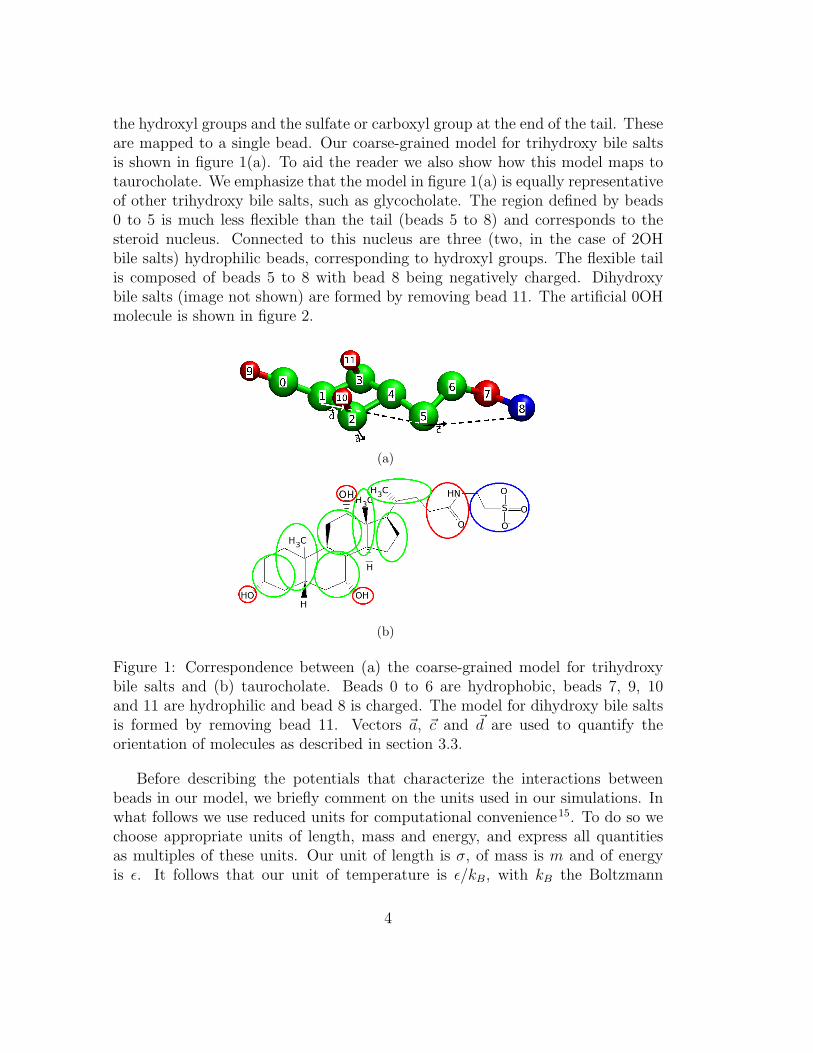
the hydroxyl groups and the sulfate or carboxyl group at the end of the tail. Theseare mapped to a single bead. Our coarse-grained model for trihydroxy bile saltsis shown in figure 1(a). To aid the reader we also show how this model maps totaurocholate. We emphasize that the model in figure 1(a) is equally representativeof other trihydroxy bile salts, such as glycocholate. The region defined by beads0 to 5 is much less flexible than the tail (beads 5 to 8) and corresponds to thesteroid nucleus. Connected to this nucleus are three (two, in the case of 2OHbile salts) hydrophilic beads, corresponding to hydroxyl groups. The flexible tailis composed of beads 5 to 8 with bead 8 being negatively charged. Dihydroxybile salts (image not shown) are formed by removing bead 11. The artificial 0OHmolecule is shown in figure 2.
(a)
(b)
Figure 1: Correspondence between (a) the coarse-grained model for trihydroxybile salts and (b) taurocholate. Beads 0 to 6 are hydrophobic, beads 7, 9, 10and 11 are hydrophilic and bead 8 is charged. The model for dihydroxy bile saltsis formed by removing bead 11. Vectors ~a, ~c and ~d are used to quantify theorientation of molecules as described in section 3.3.
Before describing the potentials that characterize the interactions betweenbeads in our model, we briefly comment on the units used in our simulations. Inwhat follows we use reduced units for computational convenience15. To do so wechoose appropriate units of length, mass and energy, and express all quantitiesas multiples of these units. Our unit of length is σ, of mass is m and of energyis ε. It follows that our unit of temperature is ε/kB, with kB the Boltzmann
4
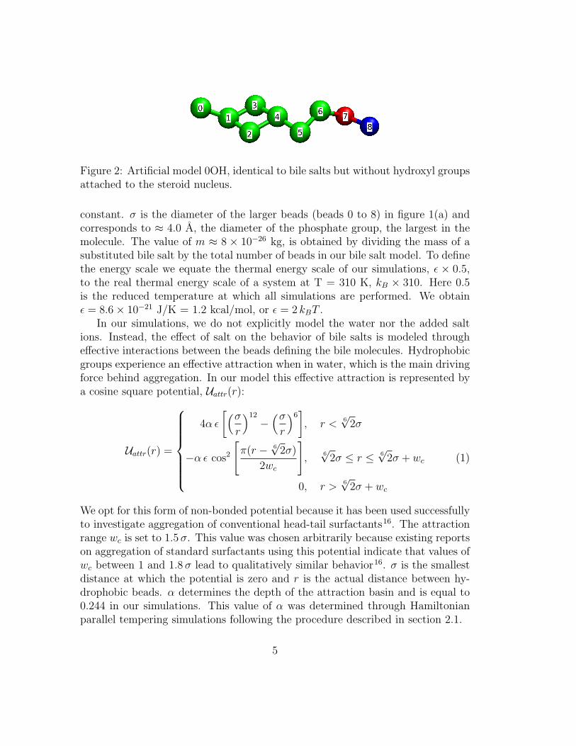
Figure 2: Artificial model 0OH, identical to bile salts but without hydroxyl groupsattached to the steroid nucleus.
constant. σ is the diameter of the larger beads (beads 0 to 8) in figure 1(a) andcorresponds to ≈ 4.0 A, the diameter of the phosphate group, the largest in themolecule. The value of m ≈ 8 × 10⁻²⁶ kg, is obtained by dividing the mass of asubstituted bile salt by the total number of beads in our bile salt model. To definethe energy scale we equate the thermal energy scale of our simulations, ε × 0.5,to the real thermal energy scale of a system at T = 310 K, kB × 310. Here 0.5is the reduced temperature at which all simulations are performed. We obtainε = 8.6× 10⁻²¹ J/K = 1.2 kcal/mol, or ε = 2 kBT .
In our simulations, we do not explicitly model the water nor the added saltions. Instead, the effect of salt on the behavior of bile salts is modeled througheffective interactions between the beads defining the bile molecules. Hydrophobicgroups experience an effective attraction when in water, which is the main drivingforce behind aggregation. In our model this effective attraction is represented bya cosine square potential, Uattr(r):
Uattr(r) =
4α ε
[(σ
r
)12
−(σ
r
)6], r <
6√
2σ
−α ε cos2
[π(r − 6
√2σ)
2wc
],
6√
2σ ≤ r ≤ 6√
2σ + wc
0, r >6√
2σ + wc
(1)
We opt for this form of non-bonded potential because it has been used successfullyto investigate aggregation of conventional head-tail surfactants16. The attractionrange wc is set to 1.5 σ. This value was chosen arbitrarily because existing reportson aggregation of standard surfactants using this potential indicate that values ofwc between 1 and 1.8 σ lead to qualitatively similar behavior16. σ is the smallestdistance at which the potential is zero and r is the actual distance between hy-drophobic beads. α determines the depth of the attraction basin and is equal to0.244 in our simulations. This value of α was determined through Hamiltonianparallel tempering simulations following the procedure described in section 2.1.
5
To a first approximation, hydrophilic groups interact equally favorably withwater and with each other. We reproduce this behavior by assigning no netattraction or repulsion between them beyond volume exclusion. The interactionsbetween hydrophilic and hydrophobic groups are favorable but much weaker thanthe effective attraction between hydrophobic groups. For this reason we alsoassign no net attraction or repulsion between hydrophobic and hydrophilic groupsbeyond volume exclusion. Volume exclusion for all particles is imposed with aWeeks-Chandler-Andersen potential, Urep(r):
Urep(r) =
4ε
[(r0
r
)12
−(r0
r
)6
+1
4
], r <
6√
2r0
0, r ≥ 6√
2r0
(2)
As before, r represents the actual distance between two beads. r0 is half of thesum of the effective diameter of any two beads and 6
√2r0 the distance below which
they repel each other. Effective diameters are set at σ for all beads except forthose with type 9, 10 and, if present, 11 (see figure 1(a)). These beads representhydroxyl groups, which are smaller than the other groups, and have a diameter of0.75 σ. Note that Urep applies also to hydrophobic particles, so the hydrophobic-hydrophobic interaction is given by Urep + Uattr.
The electrostatic interactions are modeled using a Debye-Huckel potential,Uelect:
Uelect(r) =
`BkBTQ1Q2
rexp(−κr), r < 8σ
0, r ≥ 8σ
(3)
The Debye length, κ−1, accounts for the effect of the dielectric constant of waterand of the presence of NaCl on the interactions between charged beads. Underphysiological conditions, κ−1 is approximately half the length of the bile saltmolecules. We thus assign κ−1 = 5 σ. The energy scale of the electrostaticinteractions is set by the Bjerrum length, `B, which is the distance at which theelectrostatic energy between two particles is equal to the thermal energy scale. Inour model, `B = 4.5 σ. We define a cutoff radius of 8 σ because at this distancethe interaction energy is much smaller than kBT . Q1 and Q2 represent the chargeof any two particles involved. The only charged particles in our models are thoseof type 8 (see figure 1(a)), which have a charge of −1 e where e is the absolutecharge of the electron.
Bond lengths are enforced through finite extensible nonlinear elastic (FENE)bond potentials of the form
Ubond(r) = −1
2kbond∆r2
max ln
[1−
(r
∆rmax
)2]
(4)
6
∆rmax defines the maximum possible extension of the bond and is set at 1.3 σ forbonds involving hydroxyl groups and 1.5 σ for all other bonds. The bond stiffnesskbond is set at 40 ε/σ2 for all bonds involving hydroxyl groups, and 30 ε/σ2 for allothers. These parameters (coupled with the excluded volume interactions betweenthe beads) ensure that the average bond length is 0.75 σ for bonds involvinghydroxyl groups and σ for the remaining ones, with much smaller fluctuationsthan with other standard bond potentials. Thus, the combination of FENE bondswith excluded volume interactions prevents unphysical crossing of molecules.
The shape and flexibility of the molecules is controlled through angle anddihedral potentials of the form
Uangle(θ) = kangle[1− cos(θ − θ0)] (5)
andUdihed(φ) = kdihed[1 + cos(φ− φ0)] (6)
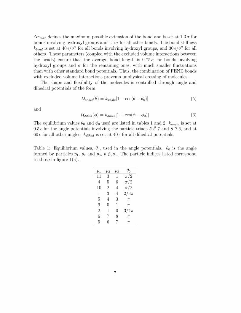
The equilibrium values θ0 and φ0 used are listed in tables 1 and 2. kangle is set at0.5 ε for the angle potentials involving the particle triads 5 6 7 and 6 7 8, and at60 ε for all other angles. kdihed is set at 40 ε for all dihedral potentials.
Table 1: Equilibrium values, θ0, used in the angle potentials. θ0 is the angleformed by particles p1, p2 and p3, p1p2p3. The particle indices listed correspondto those in figure 1(a).
p1 p2 p3 θ0
11 3 1 π/24 5 6 π/210 2 4 π/21 3 4 2/3π5 4 3 π9 0 1 π2 1 0 3/4π6 7 8 π5 6 7 π
7
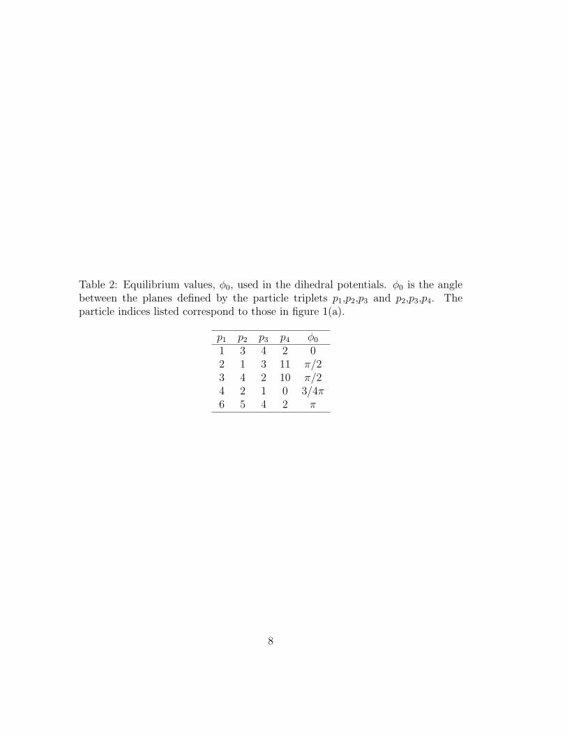
Table 2: Equilibrium values, φ0, used in the dihedral potentials. φ0 is the anglebetween the planes defined by the particle triplets p1,p2,p3 and p2,p3,p4. Theparticle indices listed correspond to those in figure 1(a).
p1 p2 p3 p4 φ0
1 3 4 2 02 1 3 11 π/23 4 2 10 π/24 2 1 0 3/4π6 5 4 2 π
8
2.1 Implementation
All simulations were implemented in the ESPResSo molecular-dynamics simula-tion package17; saved configurations were visualized using VMD18. A constantreduced temperature of 0.5 ε/kB is imposed in all simulations through a Langevinthermostat. As mentioned above, this temperature corresponds to the physiolog-ical temperature. To integrate the equations of motion, we use the velocity Verletalgorithm with a time step of 0.01 τ , where τ is the reduced unit of time. We makeno attempt to relate this unit to real time as we do not report any time-dependentbehavior.
Simulations use cubic simulation boxes and periodic boundary conditions. Aswe typically consider systems at low densities, starting configurations are gener-ated by randomly distributing molecules with identical configuration and orienta-tion in the simulation box. After a small number of integration steps performedwith force-capping to resolve possible molecular overlaps, the system is equili-brated until the average number of micelles of each size remains constant. Con-figurations are saved at every attempt to swap replicas (described in the followingsubsections) during the production phase. The production phase continues untilat least 2000 configurations are obtained.
2.1.1 Hamiltonian parallel tempering
Hamiltonian parallel tempering has been described in some detail in several refer-ences8–10 so here we give only a brief summary of the technique together with thedetails relevant for our implementation. HPT is analogous to the more widely usedtemperature parallel tempering11–14 but, instead of simulating several replicas ofthe same system at different temperatures, replicas differ in their Hamiltonianonly. The Hamiltonian, H, of a system is the sum of the kinetic energy K(p) andthe potential energy U(x):
H(x, p) = U(x) + K(p) (7)
The coordinates and momenta of all particles in the system are represented as xand p.
In our simulations, only the value of the parameter α differs between replicas.Note that α modulates principally the depth of the attraction basin between hy-drophobic beads without significantly influencing repulsion because the Urep alsoapplies to hydrophobic particles.
The range of α values used was selected so that the molecules remain asmonomers at the lowest α but become stronger micelle formers as α increases.
9
Because replicas with adjacent values of α attempt to exchange Hamiltonians pe-riodically during the simulation, the micelle size distribution of replicas with highα can be rapidly sampled. Achieving equally good sampling using simple molecu-lar dynamics or GCPT is prohibitively slow under conditions where molecules arestrong micelle formers because the residence time of molecules in micelles is long.Hamiltonian parallel tempering thus has two advantages: in a single simulationone can simultaneously test a wide range of values of a parameter and ensure thatcanonical equilibrium distributions are correctly sampled at each replica. In thiswork we use HPT simulations during the parameterization stage, to determinethe optimal value of α, and again during the production stage, to investigateaggregation of 0OH molecules.
During the parameterization stage we perform simulations of 2OH bile saltsonly. We use a total of 26 replicas with αmin ≤ α ≤ αmax = 0.19 ≤ α ≤ 0.28distributed according to
αi = αmin +αmax − αmin
no. of replicas− 1i i = 0, 1 · · · 25 (8)
All replicas have identical number density (4.5× 10⁻⁴ molecules/σ3) and numberof molecules (50). HPT is also used to investigate aggregation of 0OH molecules,for the reasons described above. In these simulations we used 32 replicas eachwith 70 molecules and 0.19 ≤ α ≤ 0.248.
The exchange of Hamiltonians between consecutive replicas is attempted every20000 steps for 2OH or 100000 steps for 0OH simulations. More frequent attemptsproved inefficient because they resulted in the same configurations swapping backand forward between replicas, not in enhanced sampling of configurations. Theprobability of accepting any given attempt so that the extended system of replicasgoes from state {Hi(xe, pe), Hi+1(xf , pf )} to state {Hi+1(xe, pe), Hi(xf , pf )} is
min[1, exp(−∆)] (9)
with∆ = β [Ui+1(xe)− Ui(xe) + Ui(xf )− Ui+1(xf )] (10)
Here β = 1/T ε−1. Hi(xe, pe) represents a replica with coordinates and momentaxe, pe for which the parameter α takes the value αi. The subscripts i, i+1, e andf were added for clarity, to emphasize that the two replicas have distinct valuesof α, particle coordinates and momenta. Note that the particle momenta do notinfluence the acceptance probability and that U need only include the part of theHamiltonian that changes between replicas (Uattr in our simulations).
From simulations of 2OH bile salts we identify the value of α for which thesystem forms micelles and, in particular, the value that yields the critical micelle
10
concentrations and micellar sizes that are in best agreement with the availableexperimental information on dihydroxy bile salts: α = 0.244. We show in section3 that the same value is found to lead to the correct aggregation behavior oftrihydroxy bile salts without the need of re-parametrization.
2.1.2 Grand canonical parallel tempering
GCPT is the method of choice to investigate aggregation. In GCPT each replicais simulated at the same temperature and volume but (unlike for HPT) at adifferent chemical potential15. Thus, a single simulation can be used to investigateaggregation over a range of concentrations. The chemical potential at each replicais enforced through frequent molecule insertions and deletions. The GCPT schemeis an efficient way to sample equilibrium distributions in our system because thenumber, size and stability of micelles decrease with decreasing chemical potential.The frequent insertion and deletion of molecules is sufficient for replicas at lowchemical potential to rapidly reach equilibrium. Because replicas with adjacentchemical potentials periodically attempt to exchange them during the simulation,replicas at higher chemical potentials can also efficiently sample their equilibriumdistributions.
Between 20 and 100 insertions and deletions are attempted between tries toswap chemical potentials in simulations of 2OH and 3OH. The probability ofaccepting a molecule insertion or deletion is given by15
P (N → N + 1) = min
[1,
V ρid
(N + 1)exp(−β[Uinter(x
N+1)− Uinter(xN)])
](11)
and
P (N → N − 1) = min
[1,
N
V ρid
exp(−β[Uinter(xN−1)− Uinter(x
N)])
](12)
N is the number of molecules in the system before the attempted insertion ordeletion, V is the volume of the simulation box, Uinter(x
N) is the intermolecularpotential energy of a system with N molecules. The superscripts N , N +1, N −1are not exponents; they were added for clarity, to emphasize the change in numberof molecules. ρid is the molecular number density of the ideal gas reservoir usedto set the chemical potential of our system. ρid is thus entirely analogous to thefugacity and we refer to it as such. The ensemble of configurations of the insertedmolecules are generated in a separate simulation of a single bile salt molecule.
The fugacity of the replicas in our simulations ranges from below the CMC toup to 20 times above it. For 2OH and for 3OH bile salts we used ρid,min = 2.2×10⁻⁴
11
and ρid,max = 0.01 molecules/σ3 and 52 replicas. The values of the fugacity aredistributed following an arithmetic progression analogous to that in equation 8.
Attempts to swap fugacities between two replicas are made every 20000 stepsfor all simulations. The probability of accepting any given swap so the ex-tended system of replicas goes from state {[(xe, pe), ρid,i], [(xf , bf ), ρid,i+1]} to state{[(xe, pe), ρid,i+1], [(xf , bf ), ρid,i]} is
min[1, (ρid,i)
Nf−Ne (ρid,i+1)Ne−Nf
](13)
where Ne and Nf are the number of molecules in the two replicas. As above, theindices i, i + 1, e and f were added for clarity, to emphasize that the two replicashave distinct fugacities, coordinates and momenta.
3 Results and discussion
3.1 Critical micellar concentrations, aggregation numbersand micellar shape
Having determined the optimal value of α from canonical HPT simulations atconcentrations near the experimental values of the CMC, we proceed to investigateaggregation of 2OH and 3OH bile salts at various concentrations using GCPT. Toidentify micelles we define a connectivity criterion between neighboring molecules:molecules are considered a part of the same aggregate if their centers of mass arewithin 3 σ of each other. This criterion is chosen based on the radial distributionfunction (G(r)) of the centers of mass (COM) of 2OH molecules, shown in figure 3for a bile salt concentration near the CMC. The form of the curve for distances< 3σ does not depend on bile salt concentration. Small variations in the thresholddistance used to define nearest neighbors do not affect our results.
12
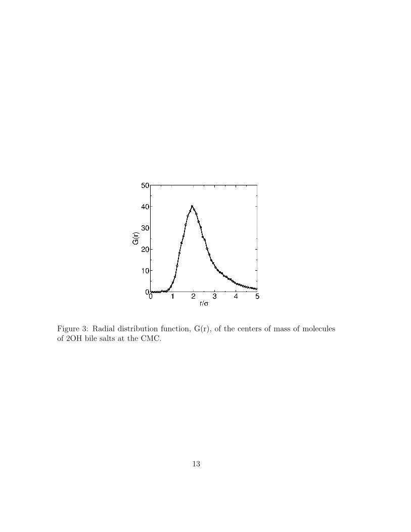
Figure 3: Radial distribution function, G(r), of the centers of mass of moleculesof 2OH bile salts at the CMC.
13
The CMC is an important property of a surfactant, so it is useful to evaluatehow well our models reproduce it. The experimentally determined CMC is thelowest concentration at which the behavior of the surfactant solution changes,indicating that the system response begins to be dominated by micelles and notmonomers. The definition of the CMC is not unique: different experimentalmethods normally lead to (slightly) different values19. Here we define the CMCas the concentration at which 50% of the molecules exist in aggregates.
In table 3 we present the value of the CMC obtained for 2OH bile salts.Analogous information is given in table 4 for 3OH bile salts. Volume fraction isthe natural way to express concentration in simulations that use reduced unitsbecause concentrations are then independent of the mapping of σ to S.I. units.Because experimental CMCs are normally reported in units of mole per unitvolume, we report them both in volume fraction and mM. The experimentallydetermined CMCs for various conjugated dihydroxy bile salts are also presentedin both units to faciliate comparisons.
Our minimal model slightly overestimates the CMC. This small discrepancy isnot surprising as during model parameterization we opted to enhance agreementof aggregation numbers with experiment at the expense of agreement of CMCs.Nevertheless, the present model distinguishes between di- and trihydroxy bilesalts: in agreement with experiment, our predicted CMC for trihydroxy bile saltsis higher than for dihydroxy ones. The fact that the model appears to overestimatethe CMC implies only that care should be taken when using it to predict CMCsof mixes of bile salts and other molecules. This limitation does not impact themodel’s applicability in studies of micelle structure and formation mechanism.
14
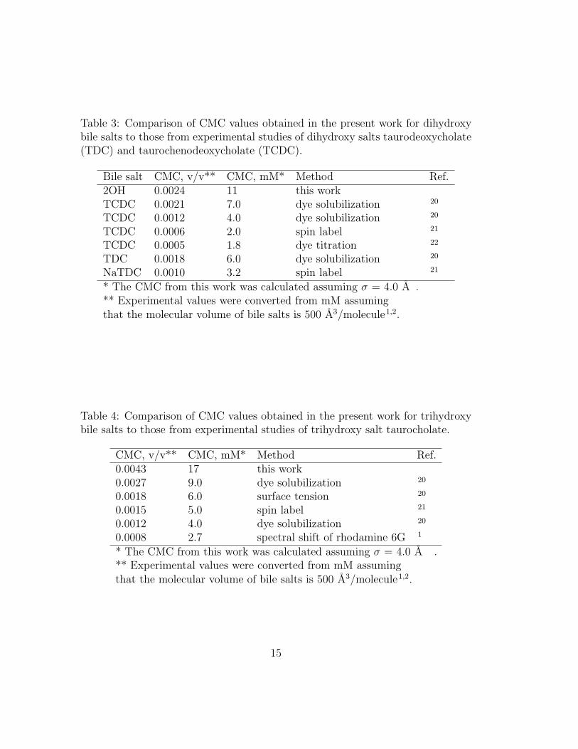
Table 3: Comparison of CMC values obtained in the present work for dihydroxybile salts to those from experimental studies of dihydroxy salts taurodeoxycholate(TDC) and taurochenodeoxycholate (TCDC).
Bile salt CMC, v/v** CMC, mM* Method Ref.2OH 0.0024 11 this workTCDC 0.0021 7.0 dye solubilization 20
TCDC 0.0012 4.0 dye solubilization 20
TCDC 0.0006 2.0 spin label 21
TCDC 0.0005 1.8 dye titration 22
TDC 0.0018 6.0 dye solubilization 20
NaTDC 0.0010 3.2 spin label 21
* The CMC from this work was calculated assuming σ = 4.0 A .** Experimental values were converted from mM assumingthat the molecular volume of bile salts is 500 A3/molecule1,2.
Table 4: Comparison of CMC values obtained in the present work for trihydroxybile salts to those from experimental studies of trihydroxy salt taurocholate.
CMC, v/v** CMC, mM* Method Ref.0.0043 17 this work0.0027 9.0 dye solubilization 20
0.0018 6.0 surface tension 20
0.0015 5.0 spin label 21
0.0012 4.0 dye solubilization 20
0.0008 2.7 spectral shift of rhodamine 6G 1
* The CMC from this work was calculated assuming σ = 4.0 A .** Experimental values were converted from mM assumingthat the molecular volume of bile salts is 500 A3/molecule1,2.
15
To allow further direct comparison with experiment we compute another im-portant property of surfactants, the average aggregation number. The averageaggregation number may include or exclude monomers; here we opt to calculatethe aggregation number excluding monomers, 〈nexcl.〉:
〈nexcl.〉 =
N∑n=2
n Cn
N∑n=2
Cn
(14)
Here Cn represents the concentration of micelles with aggregation number n av-eraged over all saved configurations of a replica at a given fugacity from GCPTsimulations.
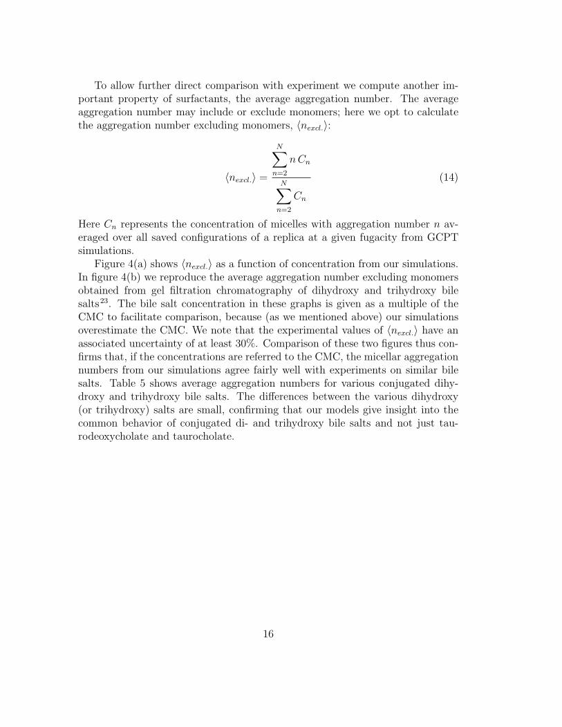
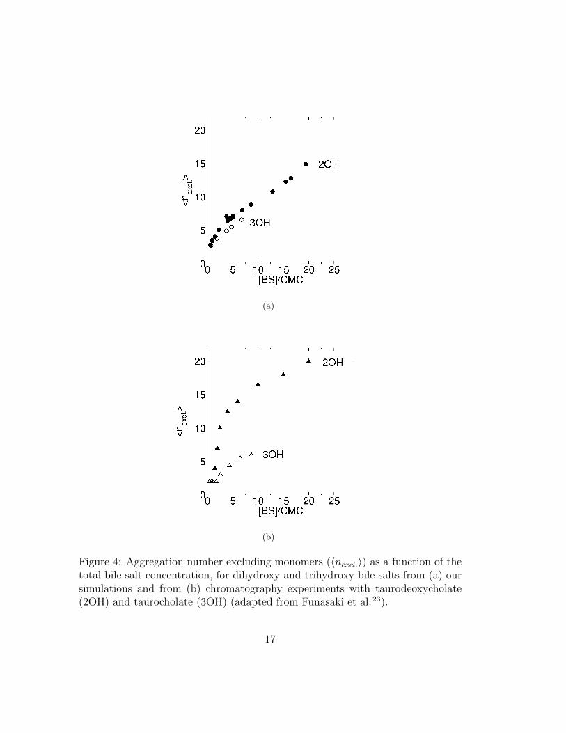
Figure 4(a) shows 〈nexcl.〉 as a function of concentration from our simulations.In figure 4(b) we reproduce the average aggregation number excluding monomersobtained from gel filtration chromatography of dihydroxy and trihydroxy bilesalts23. The bile salt concentration in these graphs is given as a multiple of theCMC to facilitate comparison, because (as we mentioned above) our simulationsoverestimate the CMC. We note that the experimental values of 〈nexcl.〉 have anassociated uncertainty of at least 30%. Comparison of these two figures thus con-firms that, if the concentrations are referred to the CMC, the micellar aggregationnumbers from our simulations agree fairly well with experiments on similar bilesalts. Table 5 shows average aggregation numbers for various conjugated dihy-droxy and trihydroxy bile salts. The differences between the various dihydroxy(or trihydroxy) salts are small, confirming that our models give insight into thecommon behavior of conjugated di- and trihydroxy bile salts and not just tau-rodeoxycholate and taurocholate.
16
(a)
(b)
Figure 4: Aggregation number excluding monomers (〈nexcl.〉) as a function of thetotal bile salt concentration, for dihydroxy and trihydroxy bile salts from (a) oursimulations and from (b) chromatography experiments with taurodeoxycholate(2OH) and taurocholate (3OH) (adapted from Funasaki et al.23).
17
Table 5: Aggregation numbers of dihydroxy and trihydroxy bile salts from exper-iments at 36 � . From ref.24 in1, pp. 318. GCDC = glycochenodeoxycholate,TCDC = taurochenodeoxycholate, TDC = taurodeoxycholate,GDC = gly-codeoxycholate, GC = glycocholate, TC = taurocholate.
Bile salt Type Agg. no.GCDC 2OH 18.2TCDC 2OH 15.2TDC 2OH 18.0GDC 2OH 16.2GC 3OH 5.6TC 3OH 4.5
18
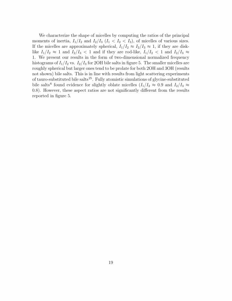
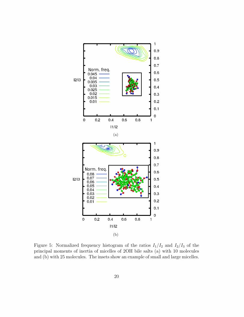
We characterize the shape of micelles by computing the ratios of the principalmoments of inertia, I1/I2 and I2/I3 (I1 < I2 < I3), of micelles of various sizes.If the micelles are approximately spherical, I1/I2 ≈ I2/I3 ≈ 1, if they are disk-like I1/I2 ≈ 1 and I2/I3 < 1 and if they are rod-like, I1/I2 < 1 and I2/I3 ≈1. We present our results in the form of two-dimensional normalized frequencyhistograms of I1/I2 vs. I2/I3 for 2OH bile salts in figure 5. The smaller micelles areroughly spherical but larger ones tend to be prolate for both 2OH and 3OH (resultsnot shown) bile salts. This is in line with results from light scattering experimentsof tauro-substituted bile salts25. Fully atomistic simulations of glycine-substitutedbile salts6 found evidence for slightly oblate micelles (I1/I2 ≈ 0.9 and I2/I3 ≈0.8). However, these aspect ratios are not significantly different from the resultsreported in figure 5.
19
(a)
(b)
Figure 5: Normalized frequency histogram of the ratios I1/I2 and I2/I3 of theprincipal moments of inertia of micelles of 2OH bile salts (a) with 10 moleculesand (b) with 25 molecules. The insets show an example of small and large micelles.
20
Small-angle neutron scattering experiments may be used to infer micellarshape. However, a direct interpretation of the experimental data is not straight-forward. Rather, the common procedure is to fit the predictions of simple modelsto the experimental data. Here we present theoretical neutron scattering curvesfor dihydroxy bile salts which can be compared with experiment and we suggesta model useful for the treatment of experimental data.
The radially averaged coherent differential cross-section per molecule, I ′C(q),at a given bile salt concentration C, is given by
I ′C(q) = 〈 1
N
N∗v∑i=1
N∗v∑j=1
bi.bjsin(q.rij)
q.rij
〉 (15)
where N is the number of molecules in the system, v is the number of beads permolecule, b is the scattering length of each bead, q is the modulus of the scatteringvector and rij is the distance between beads i and j. The scattering length of eachbead is calculated as the average over the scattering lengths of all the atoms thatcompose that bead following the mapping scheme shown in figure 1. Only q valuescompatible with the size of the simulation box may be used, so q = 2π.k/L with Lthe width of the simulation box and k = 1, 2, · · · . The average is over all recordedconfigurations from simulations at a given concentration. To facilitate comparisonbetween curves for different bile salt concentrations, we normalize I ′C(q) by theconcentration, thus obtaining IC(q) according to
IC(q) =C
C ′ I′C(q) (16)
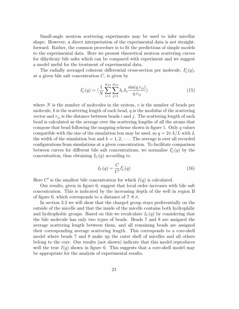
Here C ′ is the smallest bile concentration for which I(q) is calculated.Our results, given in figure 6, suggest that local order increases with bile salt
concentration. This is indicated by the increasing depth of the well in region Bof figure 6, which corresponds to a distance of 7–8 σ.
In section 3.3 we will show that the charged group stays preferentially on theoutside of the micelle and that the inside of the micelle contains both hydrophilicand hydrophobic groups. Based on this we recalculate IC(q) by considering thatthe bile molecule has only two types of beads. Beads 7 and 8 are assigned theaverage scattering length between them, and all remaining beads are assignedtheir corresponding average scattering length. This corresponds to a core-shellmodel where beads 7 and 8 make up the outer shell of micelles and all othersbelong to the core. Our results (not shown) indicate that this model reproduceswell the true I(q) shown in figure 6. This suggests that a core-shell model maybe appropriate for the analysis of experimental results.
21
Figure 6: Theoretical neutron scattering coherent differential cross-section, I(q),for dihydroxy bile salts at concentrations 8, 12 and 16 times higher than thecritical micellar concentration. In region A, q ≈ 0.05 − 0.1 A−1 and in region Bq ≈ 0.15− 0.3 A−1.
22
3.2 Micelle formation
Micelle formation is typically a cooperative process: it requires the simultaneous,collective organization of a well defined number of surfactants to overcome the freeenergy barrier for micelle formation. We investigate the cooperativity of micelleformation by computing the probability of finding micelles of any given size at agiven bile salt concentration. This micelle size distribution, P (n), is calculated as
P (n) =〈Nn〉∞∑i=1
〈Ni〉(17)
where Nn (or Ni) represent micelles of size n (i) and the averages are calculatedover all saved configurations for the replica of interest.
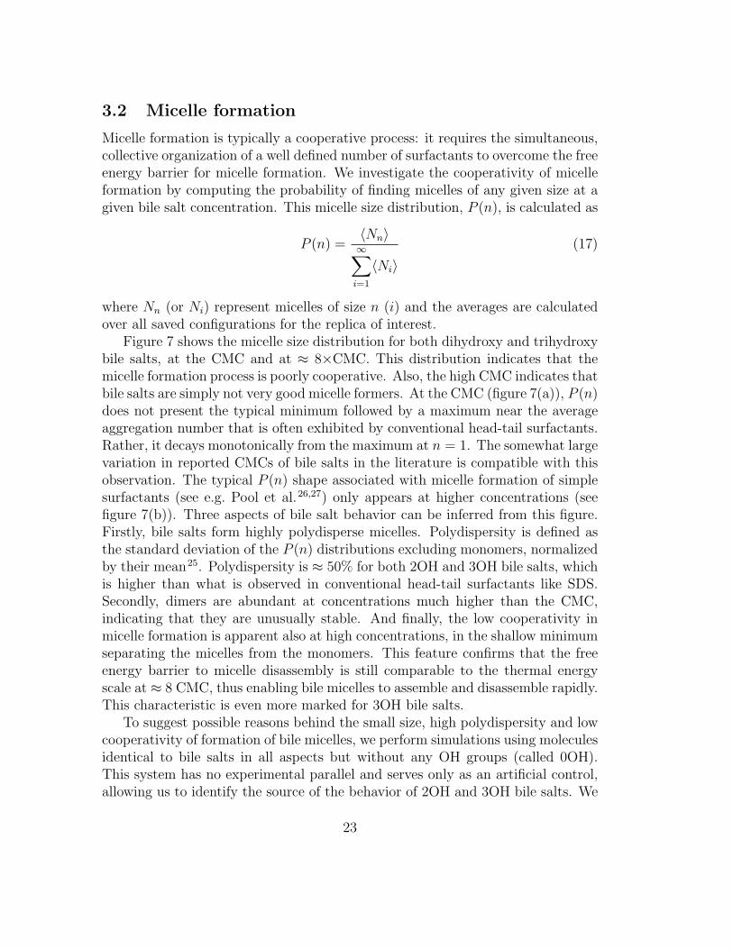
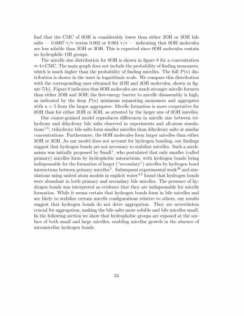
Figure 7 shows the micelle size distribution for both dihydroxy and trihydroxybile salts, at the CMC and at ≈ 8×CMC. This distribution indicates that themicelle formation process is poorly cooperative. Also, the high CMC indicates thatbile salts are simply not very good micelle formers. At the CMC (figure 7(a)), P (n)does not present the typical minimum followed by a maximum near the averageaggregation number that is often exhibited by conventional head-tail surfactants.Rather, it decays monotonically from the maximum at n = 1. The somewhat largevariation in reported CMCs of bile salts in the literature is compatible with thisobservation. The typical P (n) shape associated with micelle formation of simplesurfactants (see e.g. Pool et al.26,27) only appears at higher concentrations (seefigure 7(b)). Three aspects of bile salt behavior can be inferred from this figure.Firstly, bile salts form highly polydisperse micelles. Polydispersity is defined asthe standard deviation of the P (n) distributions excluding monomers, normalizedby their mean25. Polydispersity is ≈ 50% for both 2OH and 3OH bile salts, whichis higher than what is observed in conventional head-tail surfactants like SDS.Secondly, dimers are abundant at concentrations much higher than the CMC,indicating that they are unusually stable. And finally, the low cooperativity inmicelle formation is apparent also at high concentrations, in the shallow minimumseparating the micelles from the monomers. This feature confirms that the freeenergy barrier to micelle disassembly is still comparable to the thermal energyscale at ≈ 8 CMC, thus enabling bile micelles to assemble and disassemble rapidly.This characteristic is even more marked for 3OH bile salts.
To suggest possible reasons behind the small size, high polydispersity and lowcooperativity of formation of bile micelles, we perform simulations using moleculesidentical to bile salts in all aspects but without any OH groups (called 0OH).This system has no experimental parallel and serves only as an artificial control,allowing us to identify the source of the behavior of 2OH and 3OH bile salts. We
23
find that the CMC of 0OH is considerably lower than either 2OH or 3OH bilesalts — 0.0007 v/v versus 0.002 or 0.004 v/v — indicating that 0OH moleculesare less soluble than 2OH or 3OH. This is expected since 0OH molecules containno hydrophilic OH groups.
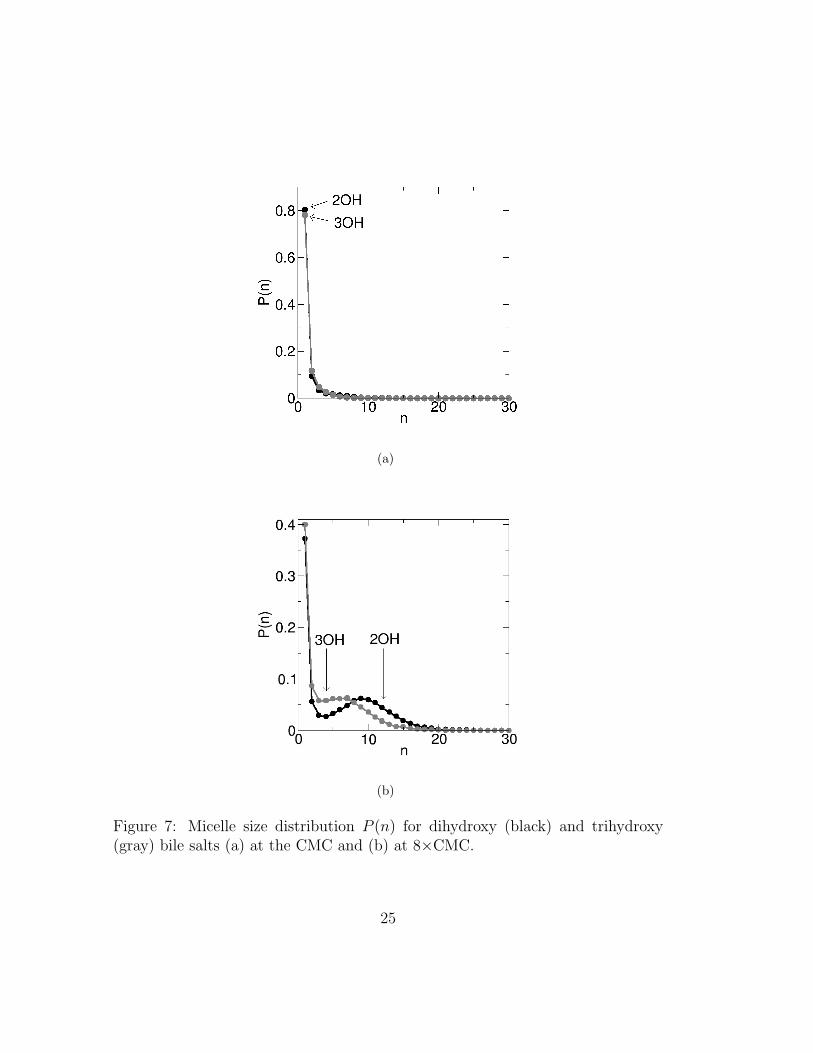
The micelle size distribution for 0OH is shown in figure 8 for a concentration≈ 4×CMC. The main graph does not include the probability of finding monomers,which is much higher than the probability of finding micelles. The full P (n) dis-tribution is shown in the inset in logarithmic scale. We compare this distributionwith the corresponding ones obtained for 2OH and 3OH molecules, shown in fig-ure 7(b). Figure 8 indicates that 0OH molecules are much stronger micelle formersthan either 2OH and 3OH: the free-energy barrier to micelle disassembly is high,as indicated by the deep P (n) minimum separating monomers and aggregateswith n < 5 from the larger aggregates. Micelle formation is more cooperative for0OH than for either 2OH or 3OH, as attested by the larger size of 0OH micelles.
Our coarse-grained model reproduces differences in micelle size between tri-hydroxy and dihydroxy bile salts observed in experiments and all-atom simula-tions1,5: trihydroxy bile salts form smaller micelles than dihydroxy salts at similarconcentrations. Furthermore, the 0OH molecules form larger micelles than either2OH or 3OH. As our model does not account for hydrogen bonding, our findingssuggest that hydrogen bonds are not necessary to stabilize micelles. Such a mech-anism was initially proposed by Small1, who postulated that only smaller (calledprimary) micelles form by hydrophobic interactions, with hydrogen bonds beingindispensable for the formation of larger (“secondary”) micelles by hydrogen bondinteractions between primary micelles1. Subsequent experimental work28 and sim-ulations using united atom models in explicit water4,5 found that hydrogen bondswere abundant in both primary and secondary bile micelles. The presence of hy-drogen bonds was interpreted as evidence that they are indispensable for micelleformation. While it seems certain that hydrogen bonds form in bile micelles andare likely to stabilize certain micelle configurations relative to others, our resultssuggest that hydrogen bonds do not drive aggregation. They are neverthelesscrucial for aggregation, making the bile salts more soluble and bile micelles small.In the following section we show that hydrophobic groups are exposed at the sur-face of both small and large micelles, enabling micellar growth in the absence ofintramicellar hydrogen bonds.
24
(a)
(b)
Figure 7: Micelle size distribution P (n) for dihydroxy (black) and trihydroxy(gray) bile salts (a) at the CMC and (b) at 8×CMC.
25
Figure 8: Micelle size distribution P (n) for 0OH at ≈ 4×CMC. The simulations ofthis model system are very time consuming and hence the raw data for P (n) arenoisy. The P (n) shown in this figure has been smoothed by averaging over 3 binsat a time. The inset shows the same data as the main graph using a logarithmicscale for the y-axis.
26
3.3 Structural properties of bile micelles
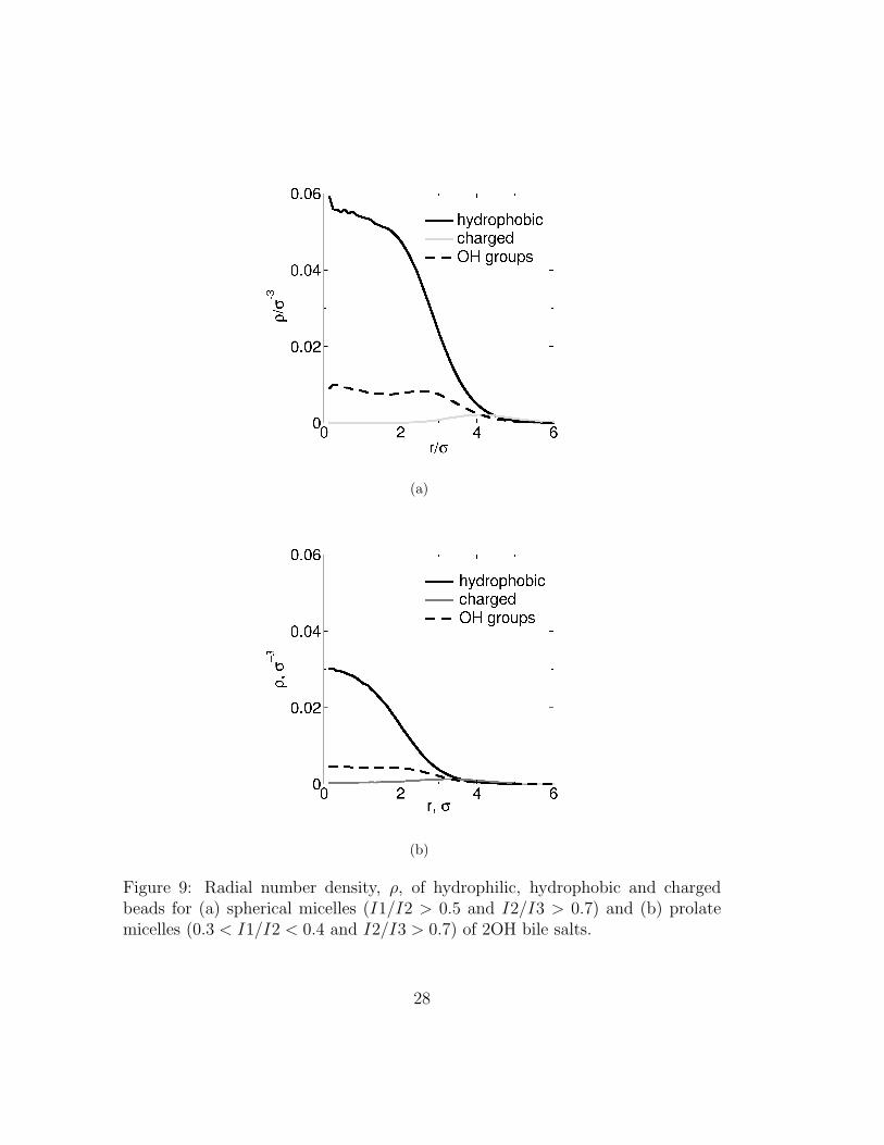
The coarse-grained inner structure of a micelle is well described by the local den-sity of each type of bead. In figure 9 we show the radial densities for hydrophilic,hydrophobic and charged beads for spherical and prolate micelles of 2OH bilesalts. The local density is given as a function of the distance to the center ofmass of the micelle for spherical micelles or, in the case of prolate ones, to themicelle’s long axis. The 3OH bile salts show similar behavior (not shown). Asexpected charged groups remain preferentially on the outside of the micelles. Asmentioned in the previous section, the hydrophobic parts of the molecule are notfully shielded from the water: they are often found at the surface of the micelle.Titration experiments using cholate and deoxycholate and all-atom simulationsare in line with our observations4,5,29. Interestingly, bile micelles do not have apurely hydrophobic core. Instead we find that the density of hydrophilic groupsinside the micelle is approximately constant.
27
(a)
(b)
Figure 9: Radial number density, ρ, of hydrophilic, hydrophobic and chargedbeads for (a) spherical micelles (I1/I2 > 0.5 and I2/I3 > 0.7) and (b) prolatemicelles (0.3 < I1/I2 < 0.4 and I2/I3 > 0.7) of 2OH bile salts.
28
The fact that the density of hydrophilic groups inside the micelle is approxi-mately constant suggests that bile molecules are not strongly oriented. To quantifythis we determined the degree to which bile molecules are oriented radially. Moreprecisely, we looked at the orientational ordering of three vectors characterizingthe 3D orientation of the bile molecule: the first vector (~a) is a unit vector perpen-dicular to the steroid nucleus (see figure 1(a)); the second, (~c) is the unit vectorassociated with the direction of the tail of the molecule (from bead 5 to 8 in the
same figure); the third vector (~d) is a unit vector associated with the direction ofthe long axis of the steroid nucleus (from bead 1 to 5 in the same figure). If the
tail of bile molecules was rigid, vectors ~c and ~d would be approximately parallel.Because the tail is not rigid, it is important to quantify the radial orientation ofboth vectors. We calculate the orientational distribution of ~r · ~a, ~r · ~c and ~r · ~d,where ~r is the unit vector in the direction that joins the center of mass of themicelle to that of a given bile-salt molecule (see figure 10).
If bile molecules would be orientationally ordered, ~c ·~r and ~d ·~r would peak at 1and ~r·~a at 0. Instead we observe very broad distributions, indicating that bile saltsmay take a wide range of orientations in spherical micelles. This indicates thatthe typical representations of small bile micelles (for examples see Padmanabhanet al.1,2) represent a small subset of
possible orientations. Our static image of bile micelles must be replaced by afluid one.
29
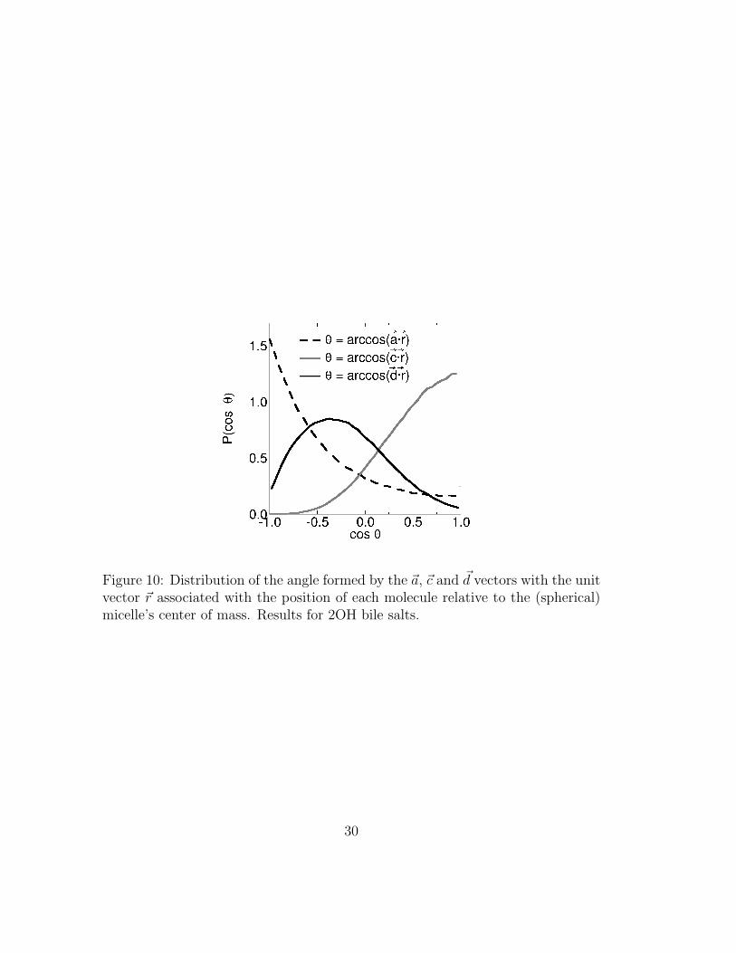
Figure 10: Distribution of the angle formed by the ~a, ~c and ~d vectors with the unitvector ~r associated with the position of each molecule relative to the (spherical)micelle’s center of mass. Results for 2OH bile salts.
30
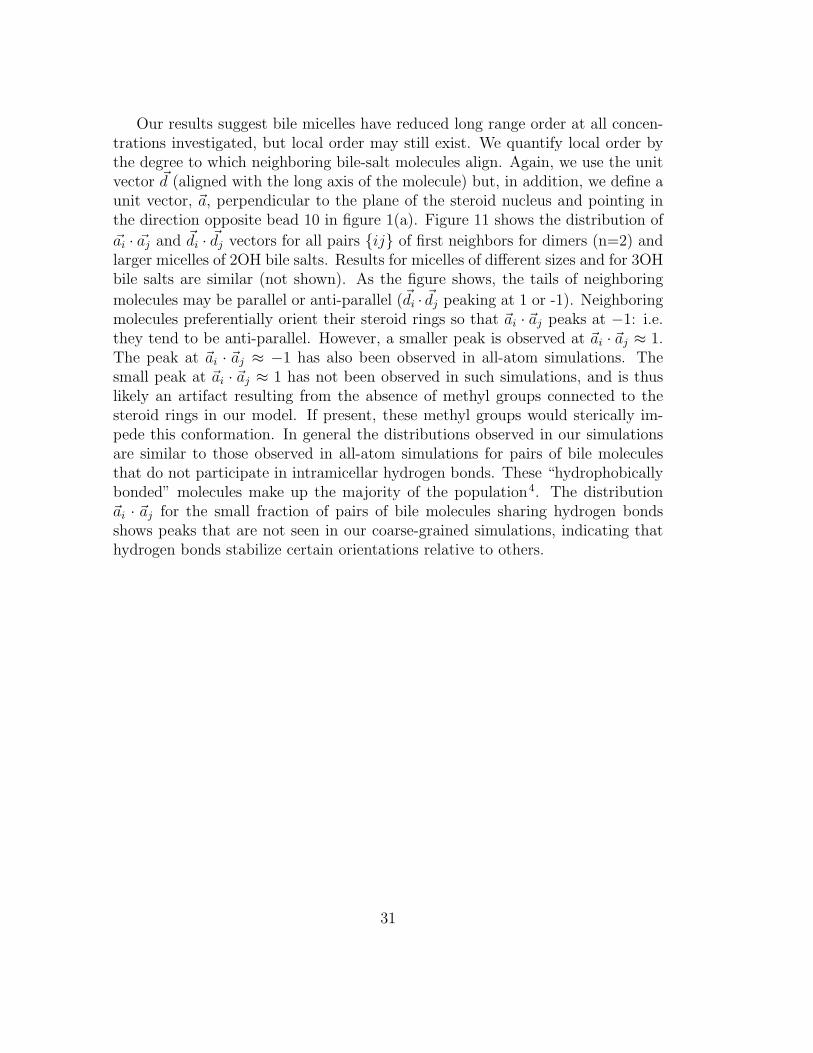
Our results suggest bile micelles have reduced long range order at all concen-trations investigated, but local order may still exist. We quantify local order bythe degree to which neighboring bile-salt molecules align. Again, we use the unitvector ~d (aligned with the long axis of the molecule) but, in addition, we define aunit vector, ~a, perpendicular to the plane of the steroid nucleus and pointing inthe direction opposite bead 10 in figure 1(a). Figure 11 shows the distribution of
~ai · ~aj and ~di · ~dj vectors for all pairs {ij} of first neighbors for dimers (n=2) andlarger micelles of 2OH bile salts. Results for micelles of different sizes and for 3OHbile salts are similar (not shown). As the figure shows, the tails of neighboring
molecules may be parallel or anti-parallel (~di · ~dj peaking at 1 or -1). Neighboringmolecules preferentially orient their steroid rings so that ~ai · ~aj peaks at −1: i.e.they tend to be anti-parallel. However, a smaller peak is observed at ~ai · ~aj ≈ 1.The peak at ~ai · ~aj ≈ −1 has also been observed in all-atom simulations. Thesmall peak at ~ai · ~aj ≈ 1 has not been observed in such simulations, and is thuslikely an artifact resulting from the absence of methyl groups connected to thesteroid rings in our model. If present, these methyl groups would sterically im-pede this conformation. In general the distributions observed in our simulationsare similar to those observed in all-atom simulations for pairs of bile moleculesthat do not participate in intramicellar hydrogen bonds. These “hydrophobicallybonded” molecules make up the majority of the population4. The distribution~ai · ~aj for the small fraction of pairs of bile molecules sharing hydrogen bondsshows peaks that are not seen in our coarse-grained simulations, indicating thathydrogen bonds stabilize certain orientations relative to others.
31
(a)
(b)
Figure 11: Distribution of the angles formed by the (a) ~a vectors (θ = arccos(~ai ·~aj)) and (b) ~d vectors (θ = arccos(~di · ~dj)) of neighboring bile salts ({ij}) in dimers(black) and in micelles with n = 12 (gray) of 2OH bile salts. The images on eitherside of each graph illustrate the preferred orientation of neighboring bile salts.
32
4 Concluding remarks
Our coarse-grained simulations of bile salts reproduce the known average aggrega-tion numbers and micellar shapes of these substances. The model slightly overes-timates the critical micelle concentrations, which limits its applicability to predictCMCs of mixed micelles but does not affect the model’s usefulness to investigatethe stability and structure of bile micelles.
The micelle size distributions obtained here suggest that the free energy barrierfor micelle disassembly is comparable to kBT even at concentrations ≈ 8×CMC.Experiments support this observation21. We propose that the high CMC of bilesalts and low micelle stability may be of biological significance. The high CMCimplies that a large amount of monomeric bile is available in the upper intesti-nal tract to rapidly form mixed dietary micelles with the products of enzymaticbreakdown of fats. It seems likely that bile solubilizes these breakdown products,yet the micelles are not very stable, thus ensuring that nutrients can easily bereleased at the intestinal wall. We are currently investigating this possibility bycomputing the relative stability of mixed micelles as a function of bile salt content.
The size and shape of surfactant aggregates may often be predicted by calcu-lating the molecular packing parameter, A/(V × `), where A is the effective areaof the head group, V the volume and ` the length of the hydrocarbon chain. Sinceour results indicate that the charged group in bile molecules stays preferentiallyon the outside of the micelle and thus acts as the head group, it is tempting tocalculate the packing parameter for bile salts and use it to predict the size andshape of equilibrium aggregates with other surfactants. However, our results sug-gest that the predictive application of the packing parameter may not work forbile salts as they may pack in many different orientations, both relative to themicelle as a whole and with respect to their neighbors.
We propose that the ability of bile salts to pack in many different orientationsin micelles is of biological significance. The low intramicellar order may explainwhy pure bile salts cannot form (undesirable) smectic phases at physiologicalconcentrations3, which may reduce the incidence of these phases in the multicom-ponent intestinal environment. We hypothesize that low intramicellar order mayalso facilitate the formation of mixed micelles with nutrients that necessarily comein a wide range of shapes, sizes and hydrophilicity. Since most nutrients resultingfrom the enzymatic breakdown of fats are poorly soluble and would thus tend toform large aggregates, the bile salt’s tendency to form small single component mi-celles may cap the size of mixed micelles, thus facilitating rapid transport acrossthe 500 µm-thick polysaccharide layer that covers the intestinal walls.
The coarse-grained model of bile salts presented here retains sufficient detail toprovide molecular-scale insight into bile salt aggregation. This model can be used
33
in conjunction with existing models of head-tail amphiphiles representative of nu-trients in the intestinal tract16 to gain further insight into the physical-chemistryof digestion. This model can also easily be modified to simulate other unusualamphiphiles, such as asphaltenes or bolaamphiphiles30,31. The low number of de-grees of freedom of these models makes them ideal to investigate local and globalequilibrium states and transition paths between them.
5 Acknowledgments
The work of the FOM Institute is part of the research program of FOM and ismade possible by financial support from the Netherlands organization for ScientificResearch (NWO). AV acknowledges support from Senter-Novem and the DutchMinistry of Economic Affairs through the Food & Nutrition Delta 2 Program(grant DFN0642300) for a joint FOM-Unilever project. DF acknowledges financialsupport from the Royal Society of London (Wolfson Merit Award) and from theERC (Advanced Grant agreement 227758). Drs. Sanne Abeln, Axel Arnold,Aimee Bailey, Rob Groot and Krassimir Velikov are cordially thanked for theirhelpful comments.
References
[1] W. H. Elliot, P. Eneroth, S. L. Hsia, D. Kritchevsky, A. Kuksis, J. T.Matschiner, P. P. Nair, R. Ryhage, J. Sjovall and D. Small, The bile acids -chemistry, physiology, and metabolism, Plenum Press, New York - London,1971, vol. 1: chemistry.
[2] I. Bekersky, J. B. Carey, H. Danielsson, A. F. Hofmann, T. F. Kellogg,D. Kritchevsky, L. Lack, H. Mekhjian, T. A. Miettinen, E. H. Mosbach,P. P. Nair, R. H. Palmer, M. P. Tyor and I. M. Weiner, The bile acids -chemistry, physiology, and metabolism, Plenum Press, New York - London,1973, vol. 2: physiology and metabolism.
[3] E. F. Marques, H. Edlund, C. La Mesa and A. Khan, Langmuir, 2000, 16,5178–5186.
[4] L. Partay, M. Sega and P. Jedlovszky, Langmuir, 2007, 23, 12322–12328.
[5] L. B. Partay, P. Jedlovszky and M. Sega, Journal of Physical Chemistry B,2007, 111, 9886–9896.
34
[6] D. B. Warren, D. K. Chalmers, K. Hutchison, W. B. Dang and C. W. Pou-ton, Colloids and Surfaces A-Physicochemical and Engineering Aspects, 2006,280, 182–193.
[7] S. Mukhopadhyay and U. Maitra, Current Science, 2004, 87, 1666–1683.
[8] Y. Sugita, A. Kitao and Y. Okamoto, Journal of Chemical Physics, 2000,113, 6042–6051.
[9] H. Fukunishi, O. Watanabe and S. Takada, Journal of Chemical Physics,2002, 116, 9058–9067.
[10] R. Affentranger, I. Tavernelli and E. E. Di Iorio, Journal of Chemical Theoryand Computation, 2006, 2, 217–228.
[11] A. P. Lyubartsev, A. A. Martsinovski, S. V. Shevkunov and P. N.Vorontsovvelyaminov, Journal of Chemical Physics, 1992, 96, 1776–1783.
[12] E. Marinari and G. Parisi, Europhysics Letters, 1992, 19, 451–458.
[13] C. J. Geyer and E. A. Thompson, Journal of the American StatisticalAssociation, 1995, 90, 909–920.
[14] Y. Sugita and Y. Okamoto, Chemical Physics Letters, 1999, 314, 141–151.
[15] D. Frenkel and B. Smit, Understanding molecular simulation - fromalgorithms to applications, Academic press, London, UK, 2nd edn., 2002,vol. 1.
[16] I. R. Cooke, K. Kremer and M. Deserno, Physical Review E, 2005, 72, 011506.
[17] H. J. Limbach, A. Arnold, B. A. Mann and C. Holm, Comput. Phys.Commun., 2006, 174, 704–727.
[18] W. Humphrey, A. Dalke and K. Schulten, Journal of Molecular Graphics,1996, 14, 33–38.
[19] D. Myers, Surfactant science and technology, Wiley Interscience, Hoboken,New Jersey, 3rd edn., 2006.
[20] A. Roda, A. F. Hofmann and K. J. Mysels, Journal of Biological Chemistry,1983, 258, 6362–6370.
[21] H. Kawamura, Y. Murata, T. Yamaguchi, H. Igimi, M. Tanaka, G. Sugiharaand J. P. Kratohvil, Journal of Physical Chemistry, 1989, 93, 3321–3326.
35
[22] M. C. Carey, J. C. Montet, M. C. Phillips, M. J. Armstrong and N. A. Mazer,Biochemistry, 1981, 20, 3637–3648.
[23] N. Funasaki, R. Ueshiba, S. Hada and S. Neya, Journal of PhysicalChemistry, 1994, 98, 11541–11548.
[24] D. M. Small, Adv. Chem. Ser., 1968, 84, 31.
[25] N. A. Mazer, M. C. Carey, R. F. Kwasnick and G. B. Benedek, Biochemistry,1979, 18, 3064–3075.
[26] R. Pool and P. G. Bolhuis, Journal of Physical Chemistry B, 2005, 109,6650–6657.
[27] P. G. Bolhuis and D. Frenkel, Physica A, 1997, 244, 45–58.
[28] D. G. Oakenfull and L. R. Fisher, Journal of Physical Chemistry, 1977, 81,1838–1841.
[29] P. Garidel, A. Hildebrand, R. Neubert and A. Blume, Langmuir, 2000, 16,5267–5275.
[30] G. Andreatta, C. C. Gonalves, G. Buffin, N. Bostrom, C. M. Quintella,F. Arteaga-Larios, E. Perez and O. C. Mullins, Energy & Fuels, 2005, 19,1282–1289.
[31] A. H. Fuhrhop and T. Y. Wang, Chemical Reviews, 2004, 104, 2901–2937.
36


![4-Phenylbutyrate modulates ubiquitination of ... · bile salts into bile [2], the MRP2/Mrp2-dependent secretion of these solutes provides the osmotic driving force for the formation](https://static.fdocuments.net/doc/165x107/5eac2e0da3ab5b4fad4f2f47/4-phenylbutyrate-modulates-ubiquitination-of-bile-salts-into-bile-2-the-mrp2mrp2-dependent.jpg)