
SIMULATION OF NONISOTHERMAL PREPREG PRESS … · SIMULATION OF NONISOTHERMAL PREPREG PRESS...
5
The 10 th International Conference on Flow Processes in Composite Materials (FPCM10) Monte Verità, Ascona, CH – July 11-15, 2010 SIMULATION OF NONISOTHERMAL PREPREG PRESS PROCESSES FOR HIGH VOLUME AUTOMOTIVE APPLICATIONS F.Klunker 1 , M.Voigt 2 , W. Wu 1 , S. Aranda 1 , W. Surjoseputro 1 and G. Ziegmann 1 1 Clausthal University of Technology, Institute of Polymer Materials and Plastics Engineering, Agricolastraße 6, 38678 Clausthal-Zellerfeld, Germany, [email protected] 2 IFC Composite GmbH, Jacob-Uffrecht-Str. 2, 39340 Haldensleben, Germany, [email protected] ABSTRACT: For the application of composite parts in the automotive industry a high volume production is necessary. The IFC Composite GmbH has developed a highly automated procedure to produce 250.000 leaf springs a year with a nonisothermal prepreg press process. With the use of flow and curing simulation the process design of leaf springs with a thickness up to 100 mm will be investigated. This paper shows models of material characterisation, mainly focussed on the thermodynamic balance of the resin. For the numerical simulation ALE-methods were coupled with conduction-convection equations to track the flow of mass and energy. The results are used to find the optimum process parameters for the control of the prepreg-press-processes. KEYWORDS: Cure simulation, flow simulation, variable geometry, ALE-methods, specific heat capacity INTRODUCTION The use of composites in automotive applications is permanently increasing due to their excellent specific mechanical properties. Especially in the case of leaf springs a weight reduction of 70% compared to steel is possible with improved mechanical performance, e.g. a fail safe behaviour. For light duty commercial vehicles up to 5.5 tons the IFC Composite GmbH has built up a production capacity of 250.000 leaf springs a year. As there is a high demand for leaf springs in heavy duty commercial vehicles, a new design will be developed, increasing the thickness from 30 mm up to 100 mm. For the production a nonisothermal prepreg press process is used: cold prepreg preforms are inserted into a hot mold which is closed by a press, due to the pressforming pressure it results in a parallel heating, flow and cure process with variable fibre volume content. In the cooperation project of Clausthal University of Technology and IFC Composite GmbH one of the aims is to setup a simulation tool for optimizing the prepreg press process. The input parameters are the pressheating and the press force of the tool. The output of the simulation is the flow field, the degree of cure and the temperature in the tool. The structure of the simulation is divided in three parts: - the mechanical interaction between fibres and tool
Transcript of SIMULATION OF NONISOTHERMAL PREPREG PRESS … · SIMULATION OF NONISOTHERMAL PREPREG PRESS...
The 10th International Conference on Flow Processes in Composite Materials (FPCM10) Monte Verità, Ascona, CH – July 11-15, 2010
SIMULATION OF NONISOTHERMAL PREPREG
PRESS PROCESSES FOR HIGH VOLUME AUTOMOTIVE APPLICATIONS
F.Klunker 1, M.Voigt 2, W. Wu1, S. Aranda1, W. Surjoseputro1 and G. Ziegmann1
1 Clausthal University of Technology, Institute of Polymer Materials and Plastics Engineering, Agricolastraße 6, 38678 Clausthal-Zellerfeld, Germany, [email protected] 2 IFC Composite GmbH, Jacob-Uffrecht-Str. 2, 39340 Haldensleben, Germany, [email protected] ABSTRACT: For the application of composite parts in the automotive industry a high volume production is necessary. The IFC Composite GmbH has developed a highly automated procedure to produce 250.000 leaf springs a year with a nonisothermal prepreg press process. With the use of flow and curing simulation the process design of leaf springs with a thickness up to 100 mm will be investigated. This paper shows models of material characterisation, mainly focussed on the thermodynamic balance of the resin. For the numerical simulation ALE-methods were coupled with conduction-convection equations to track the flow of mass and energy. The results are used to find the optimum process parameters for the control of the prepreg-press-processes. KEYWORDS: Cure simulation, flow simulation, variable geometry, ALE-methods, specific heat capacity
INTRODUCTION The use of composites in automotive applications is permanently increasing due to their excellent specific mechanical properties. Especially in the case of leaf springs a weight reduction of 70% compared to steel is possible with improved mechanical performance, e.g. a fail safe behaviour. For light duty commercial vehicles up to 5.5 tons the IFC Composite GmbH has built up a production capacity of 250.000 leaf springs a year. As there is a high demand for leaf springs in heavy duty commercial vehicles, a new design will be developed, increasing the thickness from 30 mm up to 100 mm. For the production a nonisothermal prepreg press process is used: cold prepreg preforms are inserted into a hot mold which is closed by a press, due to the pressforming pressure it results in a parallel heating, flow and cure process with variable fibre volume content. In the cooperation project of Clausthal University of Technology and IFC Composite GmbH one of the aims is to setup a simulation tool for optimizing the prepreg press process. The input parameters are the pressheating and the press force of the tool. The output of the simulation is the flow field, the degree of cure and the temperature in the tool. The structure of the simulation is divided in three parts: - the mechanical interaction between fibres and tool
The 10th International Conference on Flow Processes in Composite Materials (FPCM10) Monte Verità, Ascona, CH – July 11-15, 2010
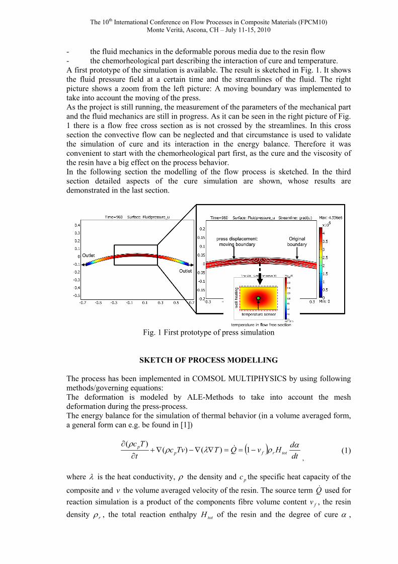
- the fluid mechanics in the deformable porous media due to the resin flow - the chemorheological part describing the interaction of cure and temperature. A first prototype of the simulation is available. The result is sketched in Fig. 1. It shows the fluid pressure field at a certain time and the streamlines of the fluid. The right picture shows a zoom from the left picture: A moving boundary was implemented to take into account the moving of the press. As the project is still running, the measurement of the parameters of the mechanical part and the fluid mechanics are still in progress. As it can be seen in the right picture of Fig. 1 there is a flow free cross section as is not crossed by the streamlines. In this cross section the convective flow can be neglected and that circumstance is used to validate the simulation of cure and its interaction in the energy balance. Therefore it was convenient to start with the chemorheological part first, as the cure and the viscosity of the resin have a big effect on the process behavior. In the following section the modelling of the flow process is sketched. In the third section detailed aspects of the cure simulation are shown, whose results are demonstrated in the last section.
Fig. 1 First prototype of press simulation
SKETCH OF PROCESS MODELLING The process has been implemented in COMSOL MULTIPHYSICS by using following methods/governing equations: The deformation is modeled by ALE-Methods to take into account the mesh deformation during the press-process. The energy balance for the simulation of thermal behavior (in a volume averaged form, a general form can e.g. be found in [1])
( )dtdHvQTTvc
tTc
totrfpp αρλρ
ρ−==∇∇−∇+
∂
∂1)()(
)(
, (1)
where λ is the heat conductivity, ρ the density and pc the specific heat capacity of the
composite and v the volume averaged velocity of the resin. The source term Q used for reaction simulation is a product of the components fibre volume content fv , the resin density rρ , the total reaction enthalpy totH of the resin and the degree of cure α ,
The 10th International Conference on Flow Processes in Composite Materials (FPCM10) Monte Verità, Ascona, CH – July 11-15, 2010
which was modeled according to Karkanas and Partridge [2] with constants 21 ,kk following an Arrhenius-equation to take into account their temperature dependancy, and the parameters mnn ,, 21 which are reaction orders, fitted by DSC-measurements:
21 )1()1( 21nmn kk
tαααα
−+−=∂∂
. (2)
The flow in porous media is modeled by combining Darcy’s Law and the continuity equation:
VVpK
−=
∇⋅∇
µ , (3)
the parameters K and µ are the permeability of the textile and the viscosity of the fluid, p the fluid pressure and VV /− the relative change of volume of the deformable porous medium. The resin movement normal to the tool surface is equivalent to a flow velocity boundary constraint which is used in the simulation. The prepreg pressing process is only one application among others using the same approach. The same modelling strategy was used e.g. for Compression RTM (CRTM) [3] , Flexible Injection [4], VARI- and RFI- Processes [5]. As in this prepreg pressprocess the fibres are already saturated, the flow- and compaction behaviour is closer to the particularities of post-filling flow in vacuum-infusion processes [6]. The permeability is strongly related to fibre volume content. As in the prepreg press process unidirectional fibres are used, there are models available, which are actually tested. The viscosity is decreasing with temperature and increasing with degree of cure. A promising model for describing the resin viscosity was found by Henne [7], as it includes a minimum temperature for viscosity. As in real measurements the viscosity in dependence of temperature 𝑇𝑇 doesn’t show a straight line on a logarithmic y- scale, this idea was modified by using a power of a WLF-equation and a cure-factor:
𝜂𝜂(𝑇𝑇,𝑇𝑇𝑔𝑔) = 𝐴𝐴0 �𝑇𝑇𝑔𝑔1−𝑇𝑇𝑔𝑔0𝑇𝑇−𝑇𝑇𝑔𝑔0−𝐴𝐴1
�𝐴𝐴2�𝑇𝑇𝑔𝑔𝑔𝑔𝑔𝑔𝑔𝑔 −𝑇𝑇𝑔𝑔0
𝑇𝑇𝑔𝑔𝑔𝑔𝑔𝑔𝑔𝑔 −𝑇𝑇𝑔𝑔�𝐴𝐴3
, (4)
where 𝑇𝑇𝑔𝑔 is the glass transition temperature ,𝑇𝑇𝑔𝑔0,𝑇𝑇𝑔𝑔1,𝑇𝑇𝑔𝑔𝑔𝑔𝑔𝑔𝑔𝑔 are the glass transition temperatures at the degrees of cure of 𝛼𝛼 = 0,𝑎𝑎 = 1 and the resin specific gelpoint.
RESULTS OF CURE SIMULATION
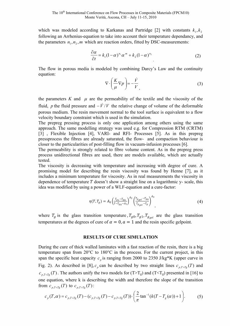
During the cure of thick walled laminates with a fast reaction of the resin, there is a big temperature span from 20°C to 180°C in the process. For the current project, in this span the specific heat capacity pc is ranging from 2000 to 2350 J/kg*K (upper curve in Fig. 2). As described in [8], pc can be described by two straight lines )(, Tc TgTp > and
)(, Tc TgTp < . The authors unify the two models for (T>Tg) and (T<Tg) presented in [16] to one equation, where k is describing the width and therefore the slope of the transition from )(, Tc TgTp < to )(, Tc TgTp > :
+−⋅−−= −
<>> 1))(((tan2))()(()(),( 1,,, α
πα gTgTpTgTpTgTpp TTkTcTcTcTc . (5)
The 10th International Conference on Flow Processes in Composite Materials (FPCM10) Monte Verità, Ascona, CH – July 11-15, 2010
Fig. 2 Measurement and modelling of the specific heat capacity
Very often, the energy balance (1) is simplified to
( )dtdHvTTvc
tTc totrfpp
αρλρρ −=∇∇−∇+∂∂ 1)()(
, (6)
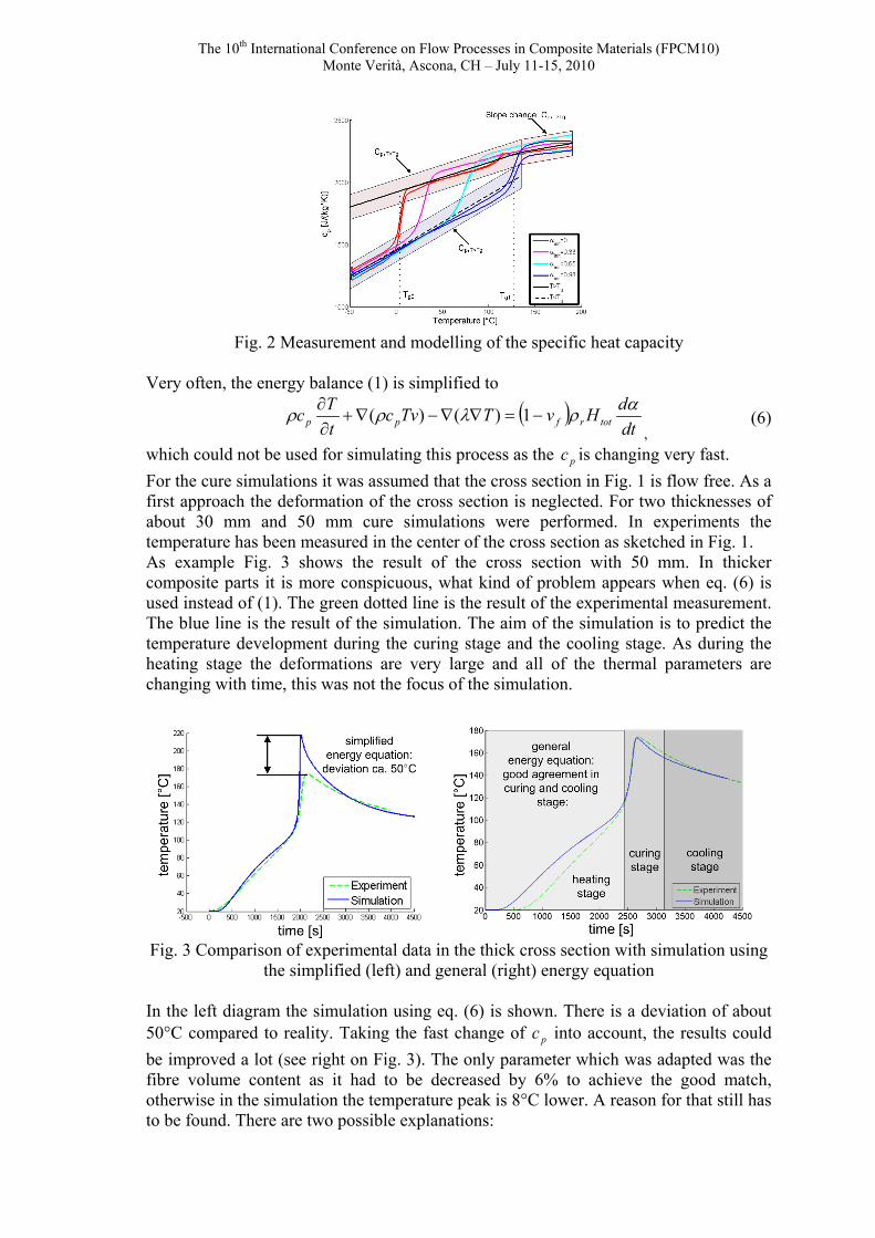
which could not be used for simulating this process as the pc is changing very fast. For the cure simulations it was assumed that the cross section in Fig. 1 is flow free. As a first approach the deformation of the cross section is neglected. For two thicknesses of about 30 mm and 50 mm cure simulations were performed. In experiments the temperature has been measured in the center of the cross section as sketched in Fig. 1. As example Fig. 3 shows the result of the cross section with 50 mm. In thicker composite parts it is more conspicuous, what kind of problem appears when eq. (6) is used instead of (1). The green dotted line is the result of the experimental measurement. The blue line is the result of the simulation. The aim of the simulation is to predict the temperature development during the curing stage and the cooling stage. As during the heating stage the deformations are very large and all of the thermal parameters are changing with time, this was not the focus of the simulation.
Fig. 3 Comparison of experimental data in the thick cross section with simulation using
the simplified (left) and general (right) energy equation In the left diagram the simulation using eq. (6) is shown. There is a deviation of about 50°C compared to reality. Taking the fast change of pc into account, the results could be improved a lot (see right on Fig. 3). The only parameter which was adapted was the fibre volume content as it had to be decreased by 6% to achieve the good match, otherwise in the simulation the temperature peak is 8°C lower. A reason for that still has to be found. There are two possible explanations:

The 10th International Conference on Flow Processes in Composite Materials (FPCM10) Monte Verità, Ascona, CH – July 11-15, 2010
- The heat conductivity was assumed to be constant and measured in totally cured state, and thus it is higher than in the partly cured state.
- During the parallel heating and pressing stage the fibre volume content is not homogeneous in the whole cross section: As the thick walled leaf spring has a variable thickness in flow direction, the center of the thin cross section are already heated up and cured before the resin in the thick sections are heated up, having the ability to flow. This could possibly result in lower fibre volume contents.
CONCLUSIONS AND OUTLOOK
A first prototype of a simulation tool for prepreg pressing processes is implemented. As the project is still in progress, the missing parameters for the flow simulation have to be determined. The simulation of cure already shows good results compared to reality, measured in a flow free cross section in the tool. In a next step, this should be combined with flow simulation to predict the flow and the cure behaviour in the whole tool.
ACKNOWLEDGMENTS We thank the Bundesministerium für Wirtschaft und Technologie for supporting the project.
REFERENCES
1. K.M. Pillai, M.S. Munagavalasa, “Governing equations for unsaturated flow through woven fiber mats. Part 2. Non-isothermal reactive flows”, Composites: Part A 35, 2004, pp. 403–415.
2. P. Karkanas, K. Partridge, D. Attwood, “Modelling the Cure of a Commercial Epoxy, Resin for Applications in Resin Transfer Moulding”, Polymer International, Vol. 41, 1996, pp.183–191.
3. P. Bhat, J. Merotte, P. Simacek, S.G. Advani, “Process analysis of compression resin transfer molding”, Composites: Part A 40,2009, pp.431–441.
4. E. Ruiz, B. Touraine, S. Soukane: “Flexible injection: a novel LCM tech-nology for low cost manufacturing of high performance composites. PART II – NUMERICAL MODEL”, FPCM9, 8.-10th July 2008, Montreal.
5. C.H. Park and A. Saouab, “A analytical modeling of composite molding be resin infusion with flexible tooling: VARI and RFI processes”, Journal of COMPOSITE MATERIALS, Vol. 43, No. 18/2009, pp. 1877-1900.
6. P. Simacek, D. Heider, J.W. Gillespie Jr., S.G. Advani, “Post-filling flow in vacuum assisted resin transfer molding processes: Theoretical analysis”, Composites: Part A 40, 2009, pp. 913–924.
7. M. Henne, C. Breyer, M. Niedermeier, P. Ermanni, “A new kinetic and viscosity model for liquid composite molding simulations in an industrial environment”, Polymer composites, 2004, vol. 25, no3, pp. 255-269.
8. J.M. Balvers, H.E.N. Bersee, A. Beukers, “Determination of cure dependent properties for curing simulation of thick walled composites”. 49th AIAA/ASME/ASCE/AHS/ASC, April 2008, Schaumburg, IL.