Simulation of Crack Propagation in a Centrifugal Pump Casing
18
www.clydepumps.com 1 © CLYDEUNION Pumps 2011 Simulation of crack propagation in a centrifugal pump casing Ramana .Podugu Dy Manager-FEA CUEC Bangalore
description
Simulation of Crack Propagation in a Centrifugal Pump Casing
Transcript of Simulation of Crack Propagation in a Centrifugal Pump Casing

www.clydepumps.com1© CLYDEUNION Pumps 2011
Simulation of crack propagation in a centrifugal pump casing
Ramana .Podugu
Dy Manager-FEA
CUEC
Bangalore
www.clydepumps.com2© CLYDEUNION Pumps 2011
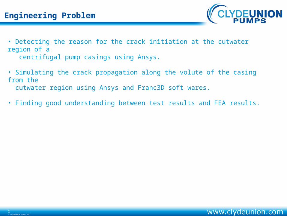
Engineering Problem
• Detecting the reason for the crack initiation at the cutwater region of a centrifugal pump casings using Ansys.
• Simulating the crack propagation along the volute of the casing from the cutwater region using Ansys and Franc3D soft wares.
• Finding good understanding between test results and FEA results.

www.clydepumps.com3© CLYDEUNION Pumps 2011
Meshing Model
Boundary conditions
Hydro static pressure 12.4Mpa (1800 psi) is
applied normal to the wetted surface.
Static stress analysis
Boundary conditionsBoundary conditions
Loading conditions Material data:
www.clydepumps.com4© CLYDEUNION Pumps 2011
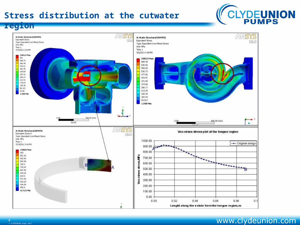
Stress distribution at the cutwater region

www.clydepumps.com5© CLYDEUNION Pumps 2011
Work flow between ansys and Franc 3D
Global Model
Local Model Sub modeling approach
• The area where crack has initiated is separated from
the main model and considered as local model
•The main model is considered as global model .
• The both parts are written into CDB files with the
boundary and pressure conditions.
• Used sub modelling approach to save the runtime
and computation time.

www.clydepumps.com6© CLYDEUNION Pumps 2011
Crack insertion procedure in Franc3D
Crack type
Crack sizeCrack size
Crack orientation
Crack front radius
Mesh refinement at the cutwater region in franc3D

www.clydepumps.com7© CLYDEUNION Pumps 2011
Connection between franc3D and Ansys

www.clydepumps.com8© CLYDEUNION Pumps 2011
Stress intensity factor
The Initial stress concentration at the crack insertion is 95 Ksi inch^0.5
Finding SIF using J-Integral
AB
www.clydepumps.com9© CLYDEUNION Pumps 2011
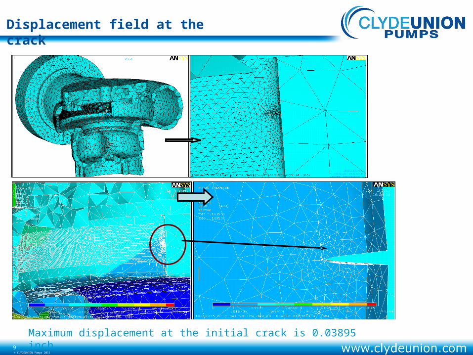
Displacement field at the crack
Maximum displacement at the initial crack is 0.03895 inch

www.clydepumps.com10© CLYDEUNION Pumps 2011
Maximum Von-misses stress at the initial crack is 798030 Psi
Plastic zone ahead of the crack tip
Stress field at the crack

www.clydepumps.com11© CLYDEUNION Pumps 2011
Crack Propagation techniques
Once the SIF solution for a given crack front is obtained, FRANC3D provides tools to estimate a new, propagated crack front. Because KI is in generally not constant along the crack front, the crack will not propagate evenly across the font . The user specifies the maximum propagation increment anywhere along the crack, delta amax, which would of course corresponding to the point where KI is highest. The crack extension everywhere else on the crack front is calculated based on the Paris power law.

www.clydepumps.com12© CLYDEUNION Pumps 2011
Crack front at the 73 load step
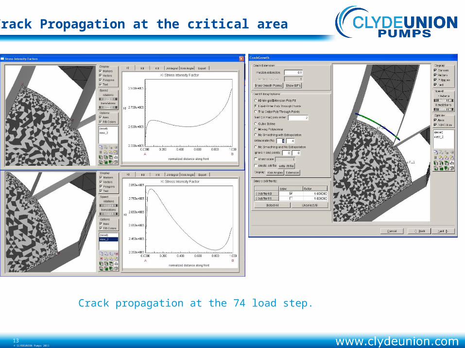
Crack Propagation at the critical area
www.clydepumps.com13© CLYDEUNION Pumps 2011
Crack propagation at the 74 load step.
Crack Propagation at the critical area
www.clydepumps.com14© CLYDEUNION Pumps 2011
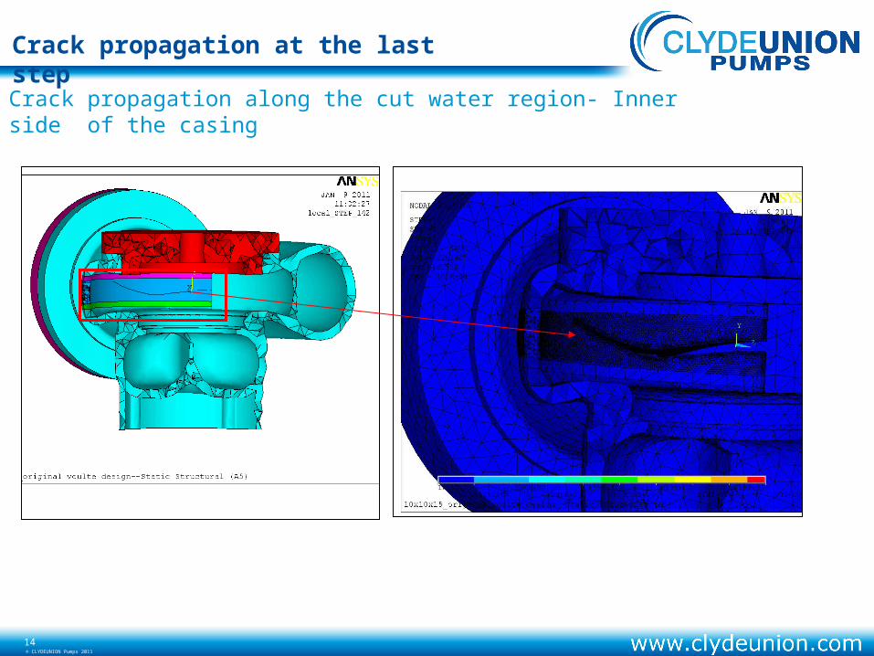
Crack propagation along the cut water region- Inner side of the casing
Crack propagation at the last step

www.clydepumps.com15© CLYDEUNION Pumps 2011
Crack propagation along the cut water region- outer side of the casing
Crack propagation at the last step

www.clydepumps.com16© CLYDEUNION Pumps 2011
Results
SIF plot along the crack lenght
0.00
50.00
100.00
150.00
200.00
250.00
300.00
350.00
0.000 2.000 4.000 6.000 8.000 10.000 12.000 14.000
Crack lenght ,inch
SIF
,Ksi
ro
ot
squ
are
(in
ch) Original design

www.clydepumps.com17© CLYDEUNION Pumps 2011
Crack formed at the cutwater region (inside the casing)
Results validation
FEA results Test results

www.clydepumps.com18© CLYDEUNION Pumps 2011
Crack formed at the cutwater region (outside the casing)
Results validation
FEA results Test results