Simulation of Blade Casing Interaction Phenomena in Gas ...
10
SIMULATION OF BLADE CASING INTERACTION PHENOMENA IN GAS TURBINES RESULTING FROM HEAVY TIP RUBS USING AN IMPLICIT TIME MARCHING METHOD Robin J Williams Design Systems & Mechanical Methods ML-78 Rolls-Royce plc Derby, DE24 8BJ, UK ABSTRACT Severe rubs between gas turbine blades and engine casings can in extreme cases result in damaging blade vibration levels and rapid loss of casing lining material. Even for more minor rubs, the wear in the lining material will result in increase tip gaps and a consequent loss in efficiency. Major rub events are extremely rare in practice, and there is seldom any useful diagnostic evidence of the root cause of the behaviour. Moreover, traditional analysis methods are not suitable for exploring the wide range of potential conditions under which an unstable vibration response might be initiated. A new modelling technique has been developed for modelling blade casing rubs which includes a detailed model of the interaction with liner wear. The method is time based, but is very efficient, enabling a wide range of initiating conditions to be explored. A series of examples have been developed to firstly: demonstrate the method is robust and reliable, and secondly: to investigate potential interaction phenomena under representative simulated conditions. The method has been applied to a real blade example, for which severe wear is known to have occurred. The method predicts that instability may occur above a threshold level of tip rub severity, and also demonstrates the improvement in an alternative blade design for which rub tolerance is known to be superior. INTRODUCTION The contact forces resulting from high-speed intermittent rubs between gas turbine rotor blades and engine casing linings may induce transient aerofoil vibration. This will modulate the contact forces at a frequency which is synchronous with the blade natural vibration frequencies, and in extreme cases, an unstable or limit cycle vibration response may result. This is characterised by heavy wear in the liner material that may be deeper than the nominal incursion depth, and the wear pattern may also be circumferentially periodic. This phenomena falls outside the scope of traditional engine rotordynamics analyses and aerofoil forced response analyses where the whole engine and aerofoil dynamic behaviour are considered independently. Detailed coupled casing and blade models using explicit Finite Element Methods are used for blade release impact simulations, but these models are generally too computationally expensive to run for the timescales required for the dynamic response to become fully developed. In recent years there has been considerable interest in the measurement and prediction of tip rub phenomena. In particular, a highly developed test facility is described in [1], which enables the response to repeated short duration intense rubs to be measured. Corresponding numerical modelling of the casing response to moving loads is described in [2] and the contact stiffness properties of rubbing blades is developed in [3]. However, while this and other research addresses the component parts of blade casing interaction in much more detail than is presented here, the entire dynamic system has not been assembled to the level necessary to enable self-sustaining dynamic response behaviour to be predicted. Traditionally within Rolls-Royce, detailed FE models of gas turbine engines are heavily reduced for dynamics and vibration analysis, where the reduction is usually achieved using the Component Mode Synthesis (CMS) method [4]. The rotors are generally reduced to a centreline only representation, and the effects of rotation are restricted to gyroscopic force terms applied to the rotor axis. This methodology has been extended, while retaining the basic centre-line rotor configuration, to enable the interaction between individual blades and the casing to be simulated. Discrete stationary reduced FE models of individual blades are processed concurrently with an engine Proceedings of ASME Turbo Expo 2011 GT2011 June 6-10, 2011, Vancouver, British Columbia, Canada GT2011-4 1 Copyright © 2011 by Rolls-Royce plc
Transcript of Simulation of Blade Casing Interaction Phenomena in Gas ...

SIMULATION OF BLADE CASING INTERACTION PHENOMENA IN GAS TURBINES
RESULTING FROM HEAVY TIP RUBS USING AN IMPLICIT TIME MARCHING
METHOD
Robin J Williams Design Systems & Mechanical Methods ML-78
Rolls-Royce plc Derby, DE24 8BJ, UK
ABSTRACT Severe rubs between gas turbine blades and engine casings
can in extreme cases result in damaging blade vibration levels
and rapid loss of casing lining material. Even for more minor
rubs, the wear in the lining material will result in increase tip
gaps and a consequent loss in efficiency. Major rub events are
extremely rare in practice, and there is seldom any useful
diagnostic evidence of the root cause of the behaviour.
Moreover, traditional analysis methods are not suitable for
exploring the wide range of potential conditions under which an
unstable vibration response might be initiated.
A new modelling technique has been developed for
modelling blade casing rubs which includes a detailed model of
the interaction with liner wear. The method is time based, but is
very efficient, enabling a wide range of initiating conditions to
be explored. A series of examples have been developed to
firstly: demonstrate the method is robust and reliable, and
secondly: to investigate potential interaction phenomena under
representative simulated conditions. The method has been
applied to a real blade example, for which severe wear is known
to have occurred. The method predicts that instability may
occur above a threshold level of tip rub severity, and also
demonstrates the improvement in an alternative blade design for
which rub tolerance is known to be superior.
INTRODUCTION
The contact forces resulting from high-speed intermittent
rubs between gas turbine rotor blades and engine casing linings
may induce transient aerofoil vibration. This will modulate the
contact forces at a frequency which is synchronous with the
blade natural vibration frequencies, and in extreme cases, an
unstable or limit cycle vibration response may result. This is
characterised by heavy wear in the liner material that may be
deeper than the nominal incursion depth, and the wear pattern
may also be circumferentially periodic. This phenomena falls
outside the scope of traditional engine rotordynamics analyses
and aerofoil forced response analyses where the whole engine
and aerofoil dynamic behaviour are considered independently.
Detailed coupled casing and blade models using explicit Finite
Element Methods are used for blade release impact simulations,
but these models are generally too computationally expensive to
run for the timescales required for the dynamic response to
become fully developed.
In recent years there has been considerable interest in the
measurement and prediction of tip rub phenomena. In
particular, a highly developed test facility is described in [1],
which enables the response to repeated short duration intense
rubs to be measured. Corresponding numerical modelling of the
casing response to moving loads is described in [2] and the
contact stiffness properties of rubbing blades is developed in
[3]. However, while this and other research addresses the
component parts of blade casing interaction in much more detail
than is presented here, the entire dynamic system has not been
assembled to the level necessary to enable self-sustaining
dynamic response behaviour to be predicted.
Traditionally within Rolls-Royce, detailed FE models of
gas turbine engines are heavily reduced for dynamics and
vibration analysis, where the reduction is usually achieved using
the Component Mode Synthesis (CMS) method [4]. The rotors
are generally reduced to a centreline only representation, and
the effects of rotation are restricted to gyroscopic force terms
applied to the rotor axis. This methodology has been extended,
while retaining the basic centre-line rotor configuration, to
enable the interaction between individual blades and the casing
to be simulated. Discrete stationary reduced FE models of
individual blades are processed concurrently with an engine
Proceedings of ASME Turbo Expo 2011 GT2011
June 6-10, 2011, Vancouver, British Columbia, Canada
GT2011-45495
1 Copyright © 2011 by Rolls-Royce plc

rotordynamics model. The interaction between the blades and
the casing is modelled by repeatedly transforming and
exchanging local displacements and forces between the rotating
and stationary coordinate frames. The blade tip vibration is
added to the rotor motion to obtain more representative
incursion depths, and the resulting friction and wear forces are
applied to the blade tips to induce representative deflection and
transient response behaviour. In addition, a non-FE eroding
model of the casing liner material is included which has
representative friction and localised wear properties.
Using this approach, it has been possible to simulate
complex blade casing interaction phenomena. As the engine and
blade modes are massively reduced, but retain representative
dynamic characteristics, the process is computationally very
efficient and it is therefore possible to simulate representative
sweep rates through resonance conditions. Conditions under
which the onset of wear-induced instability may occur can be
predicted, and have been shown to be influenced by the detailed
modeshapes of the fundamental aerofoil vibration modes.
SOLVER DESCRIPTION The models described in this paper are solved using a
Rolls-Royce proprietary implicit time marching method with
continuously variable time step adaptation, which is similar
conceptually to the Nastran NLTRAN (Solution Sequence 129)
non-linear transient method. The method is conventionally used
for modelling non-linear rotordynamics phenomena for whole
engine and aircraft simulations using large structural models,
but the method is also adaptable for much smaller scale
research studies [5].
The input models are linear mass and stiffness matrices that
have been dynamically reduced using an independent FEA
package (generally Nastran, but reduced models generated
using other Rolls-Royce proprietary software are also used). A
variety of custom designed non-linear elements have been
developed which interact with the linear model by applying
time dependent external forces at discrete points in the
structure. Internal to the solver the equations of motion are
configured in the form
tqqqftpkqqM ,,, (1)
where M and k are the linear system mass and stiffness
matrices, q is a vector of system displacements, p is a vector
of external time dependent loads, and f is a vector of response
and load dependent forces, as determined using the various non-
linear interaction elements available. A damping matrix is not
specifically included in the system model, but damping is
represented by a vector of linear velocity dependent forces in
the vector of interaction forces ( f ).
The implicit time marching solver has been optimised to
converge efficiently for the special case where the structure is
inherently linear, but with localised non-linearity. This enables
point plasticity to be modelled for example, but the method is
not suitable for more general non-linear material properties,
where the left hand side of the system equations (1) would
change with load, and an alternative method would be more
appropriate, but would result in longer solution times. However,
although the speed and robustness of the solver is beneficial, the
principal advantage of using the method is that it enables highly
specific non-linear interaction features to be modelled to a
much higher level of detail than is possible using a
commercially available FE package, and the blade casing
interaction studies described here, are heavily dependent on the
bespoke capabilities summarised in the following sections.
The solver works exclusively in the time domain, but an
equivalent multi-harmonic balance frequency domain method
has been developed by Dr. E. Petrov at Imperial College, UK
[6], which has a similar range of application elements. The
frequency domain solver is much faster for steady state
phenomena, but a time domain solution is more appropriate
where transient or load dependent boundary conditions occur.
DEVELOPMENT OF A SNUBBING MODEL At the heart of the method is a simple model for annular
snubbing, which in its most basic form is similar to that used in
other FEA codes. The displacement at a reference rotor location
is compared with that of an equivalent casing location, and if
the relative displacement exceeds the radial clearance then
contact is deemed to have occurred, and opposing contact and
friction forces are applied to the rotor and stator.
In its most basic form, the rotor and stator may be reduced
to single centreline nodes (Fig 1), and the contact forces are
then calculated using the equations.
22
srsrsr yyxxR (2)
cRR sri (3)
iR RkF , RT FF (4 & 5)
i
srT
i
srRxr
R
yyF
R
xxFF
(6)
i
srT
i
srRyr
R
xxF
R
yyFF
(7)
where x and y are the in-plane Cartesian displacement
directions, R and T are the equivalent Cylindrical directions, c is
the nominal clearance, k is the contact stiffness, F is the contact
r
s R
O
Contact force
Rotor centre-line force
Casing centre-line force
r
s R
O
Contact force
Rotor centre-line force
Casing centre-line force
Contact force
Rotor centre-line force
Casing centre-line force
Fig 1: Centreline Rotor Casing Snub Model
2 Copyright © 2011 by Rolls-Royce plc

force, is the Coulomb friction coefficient and the subscripts r,
s, and i, refer to rotor, stator, and incursion specific properties
respectively.
The contact forces are calculated assuming Coulomb
friction and linear contact stiffness. Typically, the radial
stiffness of the rotor will be much lower than that of the stator -
due to the flexibility of the blades, and the contact stiffness can
be chosen to be representative of the blade radial stiffness. This
contact model is equivalent to the NLRGAP element in
NASTRAN and is widely used for modelling snubs in
turbomachinery. The formulation is limited however, as it does
not account for the localised flexibility of the casing, or the
changes in the net radial stiffness of the contact which occur as
different numbers of blades come into contact.
Enhanced Snubbing Model The basic centreline contact model described above is
enhanced to include the effects of casing flexibility, and the
effects of multiple rotating blades, while retaining the annular
contact model for calculating the contact forces. For this
approach, the casing is not reduced to a single centreline node,
but is reduced to a ring of nodes in the plane of the contact. The
rotor is maintained as a centre-line reference node, but the
contact forces are calculated assuming the presence of virtual
rotating blades. Each blade is represented by a rotating spring,
the stiffness of which is representative of the radial stiffness of
an individual blade – Fig 2.
These spring elements are virtual, and are not included in
the input FE model. The blades are considered to rotate at the
defined speed of the rotor, and as such, the angular position of
each blade can be determined at any point in time, and contact
with the casing may only occur at these moving angular
positions. The free radial displacement of a blade is found by
resolving the net rotor centreline displacement in the radial
direction of the blade, and the corresponding radial
displacement of the casing is found by interpolation of the
nearest pair of casing nodes. The contact forces can then be
calculated using the standard annular snubbing calculation
(Equations 2-7). For the case of multiple blade contact, the
forces on each blade tip are summed at the rotor centreline
node, and the casing forces are interpolated onto the nearest
pair of casing nodes for each contacting blade. Using this
approach, the dynamic behaviour of the casing will be
representative of the localised forcing applied by the blades.
This distributed annular snubbing model is the standard
contact model used throughout the following analysis, but its
behaviour can be modified by inclusion of some of the
additional enhancements described below.
Non-linear contact stiffness The radial stiffness of typical blades is non-linear even in
cases where the behaviour remains elastic. Under the action of
the tip loading forces, which includes a lateral component due
to friction, the blade will deflect both radially and laterally, and
the resulting lean of the blade will generally give rise to a
reduction in the apparent radial stiffness. This behaviour can
only be predicted using a geometrically non-linear static load
analysis of a detailed FE blade model. A steadily increasing
load is applied to the detailed model at the blade tip at an angle
that is inclined relative to the radial direction to represent the
effects of friction. The load is applied at a representative rate to
ensure that strain rate dependency effects are captured. The
increase in radial deflection is obtained as a function of radial
load by post-processing the results of the analysis. This detailed
FE analysis may be very large, however, it is not necessary to
run the detailed model repeatedly and concurrently with the
transient analysis. It is only necessary to run the detailed model
once in order to determine the load deflection characteristics,
which can then be imported into the transient model in the form
of a table, or preferably as a smooth spline function. The
apparent radial stiffness of the blade will vary with rotor speed
due to centrifugal stiffening. The detailed model must therefore
be run at representative rotation speed, and if the speed
variation is significant, it will be necessary to interpolate using a
polynomial function between two bounding speed conditions.
It is preferable to describe non-linear stiffness properties in
terms of a load deflection characteristic, instead of a stiffness
characteristic as it enables grossly non-linear effects such as
plasticity to be included, which may include a falling
characteristic beyond the yield condition.
For monotonically increasing loading of a blade, the effects
of geometrically non-linear elastic behaviour and plasticity are
indistinguishable. However, if the detailed blade model is
unloaded from a high load condition, then the difference
between the loading and unloading characteristics provides a
measure of the reduction in nominal radial length due to
plasticity. In practice, the unload characteristic will be different
at each starting unload condition, but an approximate estimate
of the plasticity at incremental load conditions can be obtained
using a single high load unloading characteristic. This is
illustrated diagrammatically in Fig 3, where the blue trace
represents the loading characteristic and the solid red trace
represents the corresponding unloading characteristic. The
offset between these characteristics at zero load indicates the
accumulated plasticity at the peak load condition. If the
intercept of the unload characteristic is re-datumed to the origin
(dashed red line) then the difference between this and the load
Blade tip contact forces
Aggregate rotor centre-line force
Distributed Casing Forces
Radial virtual spring
representing blade
Blade tip contact forces
Aggregate rotor centre-line force
Distributed Casing Forces
Radial virtual spring
representing blade
Fig 2: Multi-blade/Flexible casing Snub Model
3 Copyright © 2011 by Rolls-Royce plc
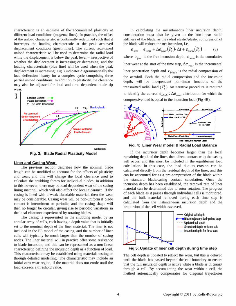
characteristic is an estimate of the accumulated plasticity at
different load conditions (magenta lines). In practice, the offset
of the unload characteristic is continually redatumed such that it
intercepts the loading characteristic at the peak achieved
displacement condition (green lines). The current redatumed
unload characteristic will be used to determine the radial load
while the displacement is below the peak level – irrespective of
whether the displacement is increasing or decreasing, and the
loading characteristic (blue line) will be used when the peak
displacement is increasing. Fig 3 indicates diagrammatically the
load deflection history for a complex cycle comprising three
partial unload conditions. In addition to plasticity, the clearance
may also be adjusted for load and time dependent blade tip
wear.
Loading Cycles
Deflection
Load
Elastic-plastic
Y 1
Y 2 Y 3
Strain-Hardened
Elastic Unload
Y - Re-Yield Conditions
Plastic Deflection
Re-datumed
Strain-Hardened
Characteristic
Loading Cycles
Deflection
Load
Elastic-plastic
Y 1
Y 2 Y 3
Strain-Hardened
Elastic Unload
Y - Re-Yield Conditions
Plastic Deflection
Re-datumed
Strain-Hardened
Characteristic
Fig. 3: Blade Radial Plasticity Model
Liner and Casing Wear The previous section describes how the nominal blade
length can be modified to account for the effects of plasticity
and wear, and this will change the local clearance used to
calculate the snubbing forces for individual blades. In addition
to this however, there may be load dependent wear of the casing
lining material, which will also affect the local clearance. If the
casing is lined with a weak abradable material, then the wear
may be considerable. Casing wear will be non-uniform if blade
contact is intermittent or periodic, and the casing shape will
then no longer be circular, giving rise to periodic variations in
the local clearance experienced by rotating blades.
The casing is represented in the snubbing model by an
annular array of cells, each having a depth value that is initially
set to the nominal depth of the liner material. The liner is not
included in the FE model of the casing, and the number of liner
cells will typically be much larger than the number of casing
nodes. The liner material will in practice offer some resistance
to blade incursion, and this can be represented as a non-linear
characteristic defining the incursion depth as a function of load.
This characteristic may be established using materials testing or
through detailed modelling. The characteristic may include an
initial zero wear region, if the material does not erode until the
load exceeds a threshold value.
In calculating the instantaneous liner incursion depth,
consideration must also be given to the non-linear radial
stiffness of the blade, as the radial elastic/plastic compression of
the blade will reduce the net incursion, i.e.
rbladerwearwearfree PetPeee , (8)
where freee is the free incursion depth, weare is the cumulative
liner wear at the start of the time step, weare is the incremental
liner penetration depth and bladee is the radial compression of
the aerofoil. Both the radial compression and the incursion
depth, will be independent non-linear functions of the
transmitted radial load ( rP ). An iterative procedure is required
to identify the correct wearblade ee : distribution for which the
compressive load is equal to the incursion load (Fig 4B).
Ra
dia
l L
oa
d
Blade Elastic/Plastic Disp Liner Erosion Depth
Total Rotor/Liner Incursion Depth
Blade Load/Disp Chic
Liner Load/Cut Chic
Threshold Load
for liner wear
Elastic Load = Erosion Load
Ra
dia
l L
oa
d
Blade Elastic/Plastic Disp Liner Erosion Depth
Total Rotor/Liner Incursion Depth
Blade Load/Disp Chic
Liner Load/Cut Chic
Threshold Load
for liner wear
Elastic Load = Erosion Load
Ra
dia
l L
oa
d
Blade Elastic/Plastic Disp Liner Erosion Depth
Total Rotor/Liner Incursion Depth
Blade Load/Disp Chic
Liner Load/Cut Chic
Threshold Load
for liner wear
Elastic Load = Erosion Load
Ra
dia
l L
oa
d
Blade Elastic/Plastic Disp Liner Erosion Depth
Total Rotor/Liner Incursion Depth
Blade Load/Disp Chic
Liner Load/Cut Chic
Threshold Load
for liner wear
Elastic Load = Erosion Load
Fig. 4: Liner Wear model & Radial Load Balance
If the incursion depth becomes larger than the local
remaining depth of the liner, then direct contact with the casing
will occur, and this must be included in the equilibrium load
calculation. In this case, the load due to erosion can be
calculated directly from the residual depth of the liner, and this
can be accounted for as a pre-compression of the blade within
the standard blade/casing contact calculation. Once the
incursion depth has been established, the removal rate of liner
material can be determined due to rotor rotation. The progress
of each blade as it passes through individual cells is monitored,
and the bulk material removed during each time step is
calculated from the instantaneous incursion depth and the
proportion of the cell width traversed.
The cell depth is updated to reflect the wear, but this is delayed
until the blade has passed beyond the cell boundary to ensure
that the full incursion depth is active while a blade is in transit
through a cell. By accumulating the wear within a cell, the
method automatically compensates for diagonal trajectories
Original cell depth
Blade trajectory during time step
Updated cell depth
Smoothed depth for force calc
Incursion depth for force calc
Original cell depth
Blade trajectory during time step
Updated cell depth
Smoothed depth for force calc
Incursion depth for force calc
Fig 5: Update of liner cell depth during time step
4 Copyright © 2011 by Rolls-Royce plc

through the cell, or where incursion is initiated or ceases part
way though a cell – Fig 5.
Lateral wear forces are generated as a result of liner
incursion. This consists of two components: a friction force due
to rubbing and an impulse force due to the increase in
momentum of the liner material following removal (wipeout
force). The friction force is calculated using Coulomb friction,
for which the friction coefficient used for wear, may be different
from the value used for calculating direct rubbing with the
casing. The impulse force arises due to the increase in
momentum resulting from accelerating the liner material up to
the blade tip speed, and is proportional to: the depth of
incursion; the volume rate of removal; and the density of the
liner material. The stagger angle of the blade is also important,
as this determines the velocity change and direction of the
ejected material – Fig 6.
The impulse force (called the wipeout force) is different
from the other contact forces considered, in that it is applied
only to the blades, as the reaction force is considered to
overcome the inertia of the virtual liner material and is therefore
not transmitted to the engine casing. The method outlined above
can be used to calculate the wipeout force under simulated ideal
conditions, but may not be representative of the behaviour of
real materials under rapid incursion conditions. If direct
measurement data (or high quality simulation data) is available,
then this can be used to define the wipeout force as a function
of incursion depth and of blade tip speed, and this can be used
directly in the simulation.
The axial hade angle of casing also has an influence on the
snubbing behaviour. If the casing is conical, then relative axial,
pitch, or yaw motion of the rotor, will reposition the axial
contact position with respect to the casing, and will change the
nominal clearance. Also, the resolved contact force will have a
small axial component and this will induce yaw and pitching
moments onto the rotor due to the high tip radius. These
additional forces may influence the rotordynamic response of
the rotor, resulting in further changes to the relative motion at
the snubbing location.
Once the incursion depth and instantaneous liner removal
rates have been established, the resulting forces can be
calculated and interpolated onto the rotor and casing nodes as in
the standard snubbing calculation.
Generally, for the case of non-uniform wear, the updating
of the liner cell depth values, results in small steps in the liner
depth as a blade moves from one cell into the next – Fig 5. The
magnitude of these steps reduces as the number of cells is
increased, but remains a finite value. This can give rise to
convergence problems if a blade is positioned very close to a
cell boundary at the end of a time step due to the step change in
contact force during the next time step. Reducing the time step
will exacerbate the problem, as the rate of change of contact
force will increase. This is addressed by introducing a linear
smoothing function for the last cell traversed within the time
step (also indicated in Fig 5), which ensures that the contact
force vary smoothly as the cell boundaries are approached. This
smoothing is only applied to the calculated force at the end of
the time step. It is not required, and should not be used when
calculating the net material removed and the removal rate, as
small errors will be introduced.
Similar convergence issues can occur at conditions where
the liner is locally fully consumed, and the blade comes into
direct contact with the casing. The change in friction coefficient
results in an instantaneous change in the tangential forces. This
is smoothed using a cubic smoothing function (Fig 7), which
operates over a small proportion of the cell width to minimise
errors, but which is effective in preventing critical time step
reduction.
C u b ic S m o o th in g a t ce ll b o u n d ary
0
0.05
0.1
0.15
0.2
0.25
0.3
0.35
0.4
0.45
0 0.5 1 1.5 2
Liner C ell W id th
Pa
ram
ete
r (
)
Uns m oothed
S m oothed
Fig 7: Cubic Smoothing function at cell boundary
Introduction of a dynamic blade model In the models described so far, individual blades have been
represented by inert non-linear springs. These have
representative static radial stiffness, but do not have damping,
and do not respond dynamically to the applied snubbing forces.
In practice, transient and periodic vibration will be induced in
the blades, which will in turn affect the contact behaviour. To
address this, additional reduced models of either individual
blades or of a full bladed assembly are introduced. The blade
models are dynamically reduced to a small number of physical
degrees of freedom at the tips of the blades.
The blade models are constructed such that they include
speed specific properties (i.e. centrifugal stiffening), but are
solved in the time domain calculation in a static reference
frame. The blade models are incorporated into the global linear
mass and stiffness matrices for the engine model, but form
vn v rel
vt
Liner Material ejected tangential
to blade tip chord
Tang rel Velocity Vt retained
Impulse due to Normal Velocity Vn
22 cosrelVdcF
sincos2
relz VdcF
vn v rel
vt
vn v rel
vt
Liner Material ejected tangential
to blade tip chord
Tang rel Velocity Vt retained
Impulse due to Normal Velocity Vn
22 cosrelVdcF
sincos2
relz VdcF
Fig 6: Liner Momentum – Staggered Blade
5 Copyright © 2011 by Rolls-Royce plc

discrete partitions with no physical connections between the
respective blade and engine partitions. The interaction is
provided purely by external forces representing the contact
behaviour.
Blade casing contact is modelled as a two stage process.
Firstly, the residual motion of each blade tip is transformed into
the current angular position of the respective blade, and is
added to the rotor motion. This transformation recognises the
nominal position of each blade within the rotor and the
integrated rotation of the shaft. Adding the blade motion to the
rotor motion changes the effective position of the blade tip, and
affects the angular position and intensity of snubbing as
indicated in Fig 8.
Secondly, the snubbing forces are calculated using the
revised blade tip positions. The snub forces are applied to the
rotor and casing model and are also transformed back into the
static frame and applied to the blade models, thereby inducing
further blade motion.
The blade and casing models are linear, and have linear
modeshapes. This will give rise to increasing errors at high
amplitudes due to the limitations of small displacement
assumptions (discussed later), and this may give rise to
unrepresentative snubbing behaviour. However, the models are
generally acceptable for blade displacements in the elastic
range.
Implementation Issues The features described in the above sections enable a
comprehensive model of rotor stator interaction to be
constructed including dynamic models of the rotor, casing,
blade and liner, and enables the effects of multi-blade contact,
plasticity and wear to be simulated. Not all of these features
need to be used at the same time, and in the examples described
next, some parts of the model are omitted.
IDEALISED TWELVE BLADE ROTOR EXAMPLE This first example considers the interaction between an
idealised bladed rotor and a rigid casing with a localised high
spot at one position on the casing periphery -Fig 9.
The disk model is flexible, and as such the diametral modes
are separated in frequency and can be readily identified from
the frequency response characteristics. The FE bladed disc
model contains 6204 tetrahedral elements and 38700 DOFs, but
is dynamically reduced such that the analysis model contains
only 2 master nodes on the tip of each blade (72 physical
DOFs), and a further 30 generalised freedoms. The complete
reduced model contains only 102 DOFs in total. However, an
Eigen solution for the reduced model demonstrated that the
modal frequencies were correct for the first three families of
diametral modes, and the static stiffness of individual blade tips
are also representative. The effects of centrifugal stiffening
were not included for this idealised example as the consequent
changes in frequency are not of interest.
Fig 10A plots the blade response for low speed rotation
with contact active on each blade. The higher time resolution
plot (Fig 10B) clearly indicates the shape of the ramp in the
radial displacement, and the build up of much larger static
deflection in the lateral and axial directions due to friction (drag
displacement). This is released as the blade passes over the
ramp, and the resulting transient response can be examined
using Fourier Analysis to reveal the responding free modes.
Fig 11 shows that most of the first and second family
modes can be identified from the response, the frequencies of
which agree with the detailed FE analysis. The first family
modes (edgewise mode) and second family (flap mode) are both
excited due to the blade tip stagger angle. This initial example
demonstrates that representative static and dynamic behaviour
of the model is predicted, which is consistent with the
properties of the unreduced modes, and with the excitation
model.
Non-rotating
blade/blisk modelsR
0
rtrt´
brb
b
Rt
F
R
r0
b F
Contact Forces
Blade Vibration
Non-rotating
blade/blisk modelsR
0
rtrt´
brb
b
Rt
F
R
r0
b F
Contact Forces
Blade Vibration
Fig 8: Interface between engine and blade models
10 5 1 degs
0.25m
0.25m
10 5 1 degs
0.25m
0.25m
10 5 1 degs
0.25m
0.25m
10 5 1 degs
0.25m
0.25m
Fig 9: Idealised Bladed Disk and Casing Ramp Models
1.38 1.40 1.42 1.44Time
0.0 0.40 0.8 1.2Time
1.6
0.002
0.001
0.000
-0.001
-0.002
Dis
pla
cem
ent
A: Slow Speed Rotation B: Expanded single Contact
— Axial Disp
— Tang Disp
— Radial Disp
Ramp Height
— Axial Disp
— Tang Disp
— Radial Disp
1.38 1.40 1.42 1.44Time
1.38 1.40 1.42 1.44Time
0.0 0.40 0.8 1.2Time
1.60.0 0.40 0.8 1.2Time
1.6
0.002
0.001
0.000
-0.001
-0.002
Dis
pla
cem
ent
A: Slow Speed Rotation B: Expanded single Contact
— Axial Disp
— Tang Disp
— Radial Disp
Ramp Height
— Axial Disp
— Tang Disp
— Radial Disp
Fig 10: Blade tip response to casing ramp
6 Copyright © 2011 by Rolls-Royce plc

0
0D
1D2D
3D 4D
5D
6D
0D
1D
2D
3D
4D 5D6D
First Family
Second Family
Cyclic Modal Frequencies:
Unreduced FE Model
Normalised Frequency
FFT of Free Response post Ramp
10
0D
1D1D2D2D
3D3D 4D4D
5D5D
6D6D
0D0D
1D1D
2D2D
3D3D
4D4D 5D5D6D6D
First Family
Second Family
Cyclic Modal Frequencies:
Unreduced FE Model
Normalised Frequency
FFT of Free Response post Ramp
1
Fig 11: FFT of transient response to single contact
Fig 12 plots the response to a frequency sweep in the
vicinity of the First Mode Third Engine order resonance.
For this example the speed of rotation is increased steadily
over a five second period to enable the build up to resonance to
be examined. The entire analysis represents approximately 270
revolutions and 3250 potential contacts with the ramp. The
sweep rate and sweep range were optimised to minimise the
effects of response lag and post resonance „ringing‟, while
retaining full resolution of the resonance peak, and minimising
the analysis time. A frequency sweep rate normalised to the
resonance frequency of 3.5% sec-1
was found to be suitable.
The analysis takes approximately 6 minutes to solve on a
2.2GHz single processor PC.
— With Friction ( = 0.1)
— Without Friction
Mode 1
6 Engine Order
0 1 2 Time
0.002
0.001
0.000
-0.001
-0.002
Dis
pla
cem
ent
3 4 5
— With Friction ( = 0.1)
— Without Friction
Mode 1
6 Engine Order
0 1 2 Time
0.002
0.001
0.000
-0.001
-0.002
Dis
pla
cem
ent
3 4 5
— With Friction ( = 0.1)
— Without Friction
Mode 1
6 Engine Order
0 1 2 Time
0.002
0.001
0.000
-0.001
-0.002
Dis
pla
cem
ent
3 4 5
Fig 12: Mode 1, 6 Engine Order Resonance
Fig 12 compares the response with and without friction
(=0.1), and demonstrates a large increase in peak response
when friction is present. This is due to the increased drag
displacement on the blade tips. The friction value used is low in
comparison with test data, but has been selected to demonstrate
the strong dependence on friction, and is not intended to be
representative of genuine liner materials.
Fig 13 shows that the number of contacts increases as the
amplitude increases near resonance. This is due to intermittent
secondary contacts with the uniform cylindrical section of the
casing. This occurs because for large lateral deflections, the
effective clearance is reduced at the extremities of the vibration
motion, and contact may therefore be induced.
0.03
B: Forces: At Resonance
Ramp
Contact
0.00 0.01 0.040.02 0.03Time (secs)
0.05
A: Forces: Off-Resonance
Radial Contact Force
Tangential Contact Force
Ramp
Contact
0.00 0.01 0.02Time (secs)
Norm
alis
ed C
onta
ct F
orc
es
0.03
B: Forces: At Resonance
Ramp
Contact
0.00 0.01 0.040.02 0.03Time (secs)
0.05
A: Forces: Off-Resonance
Radial Contact Force
Tangential Contact Force
Ramp
Contact
0.00 0.01 0.02Time (secs)
Norm
alis
ed C
onta
ct F
orc
es
0.03
B: Forces: At Resonance
Ramp
Contact
0.00 0.01 0.040.02 0.03Time (secs)
0.00 0.01 0.040.02 0.03Time (secs)
0.05
A: Forces: Off-Resonance
Radial Contact Force
Tangential Contact Force
Ramp
Contact
0.00 0.01 0.02Time (secs)
Norm
alis
ed C
onta
ct F
orc
es
A: Forces: Off-Resonance
Radial Contact Force
Tangential Contact Force
Ramp
Contact
0.00 0.01 0.02Time (secs)
Norm
alis
ed C
onta
ct F
orc
es
Fig 13: Secondary casing rubs near resonance
This effect is exaggerated for linear modeshapes, for which
planer motion of the blade tip implies that an unrepresentative
increase in the blade length occurs at high amplitude. In
practice the tip trajectory at high amplitude will describe a
shallow arc, and this will reduce the rate of incursion (Fig 14).
A: Linear Modeshape B: Representative ModeshapeA: Linear Modeshape B: Representative Modeshape
Fig 14: High amplitude modeshape errors
12 BLADE MODEL WITH LINER AND BLADE LEAN A liner model is now introduced into the simulation. This is
2mm deep but is set up with a very low nominal clearance of
0.005mm. It is not possible to introduce a ramp into a liner
model or a uniform misalignment, as this will wear away in the
early stages of the interaction, and no information will be
gathered at what might be more interesting speed conditions. It
is also not feasible to start the simulation at resonance as some
degree of frequency stiffening might take place, and is then
necessary to track the development of resonance from a lower
speed off-resonance condition. To address these issues, a casing
model was introduced for which a small annular segment
advances inwards at a slow but constant rate. The liner model,
taking its clearance datum from the casing, advances locally at
the same rate, presenting a small depth of fresh liner material to
each passing blade. This may or not be removed depending on
the blade motion - Fig 16. Note that this method of exciting the
blade is not intended to be representative of conditions a blade
would experience in practice, but is a convenient method for
ensuring consistent low level interaction over a wide frequency.
The alternative is to introduce a strong preferential initial
clearance pattern, which might influence the resulting
behaviour.
7 Copyright © 2011 by Rolls-Royce plc

0.2 0.6 1.0Time
1.4 1.8
— Nom Posn: Min Radial Motion
— +20 Posn: Negative Lean
— -20 Posn: Positive Lean
Norm
alis
ed D
ispla
cem
ent
0.2 0.6 1.0Time
1.4 1.8
— Nom Posn: Min Radial Motion
— +20 Posn: Negative Lean
— -20 Posn: Positive Lean
Norm
alis
ed D
ispla
cem
ent
0.2 0.6 1.0Time
1.4 1.8
— Nom Posn: Min Radial Motion
— +20 Posn: Negative Lean
— -20 Posn: Positive Lean
Norm
alis
ed D
ispla
cem
ent
Fig 15: Effect of Radial Modeshape on Response
The influence of aerofoil tip lean was also introduced into
this example. For real blades, the tip modeshape may not be
planar, but may include some radial motion due to lean and
stagger of the aerofoil. Consequently, the clearance will vary
periodically with blade vibration. The phase of the tip motion
may influence the severity of the interaction. For example, if the
radial motion is increasing while the tip is moving in the
direction of rotation, then the tip might have a tendency to „dig
in‟ to the casing. Conversely, if the maximum occurs when the
tip is moving rearwards, then the frictional drag might be
increased. Increased radial motion of the idealised blade model
can be synthesised by specifying a small misalignment in the
orientation of the disk, such that a small proportion of the
planer tip motion is misinterpreted as radial motion following
transformation to the rotating coordinate frame. It is not
necessary to modify the input model to achieve this, as a
parameter is available in the code to align the blade model/s
with the rotor motion at the start of the analysis. Fig 15
compares the response for different levels of misalignment. This
shows that the response is significantly higher for both positive
and negative lean, but is highest for positive lean. The response
is much nosier for the misaligned blade and there is evidence of
other modes being excited.
FULL CHORD TIP RUB EXAMPLE The final example is based on an early design standard of
compressor blade aerofoil for which tip rub induced blade
damage accompanied by high liner wear has occurred in
isolated incidents. The liner wear tends not to be uniform, but
has been associated with a dominant 6 lobed wear pattern. This
design is compared with an improved design that is known to be
more tolerant, but no quantitative measurement results are
available for either example. It was therefore necessary to
devise a set of liner parameters (density, incursion rate, rotation
frequency and acceleration rate) which are consistent with
expected engine conditions, and for which the initial blade
design is marginally unstable. The increase in stability margin
of the redesigned blade can then be used as a measure of the
improved tolerance to rubs. The analysis model consisted of a
single blade earthed on the root mating surfaces – Fig 16.
This is a design standard model including CF stiffening
equivalent to the resonant speed condition. The model was
CMS reduced to the 6 aerofoil nodes shown in Fig 16 and
included a further 100 generalised variables. The shaft and
casing were represented as inert rigid structures, as there was no
evidence of a rotordynamic influence on the behaviour. A
concentric liner with tight clearance was modelled, which
included a localised advancing high spot as described
previously. For this high-speed excitation condition, the
wipeout inertia forces are very much higher than the liner
penetration and friction forces, which were therefore not
included in the analysis for clarity. The following analyses are
not intended to be representative of particular engine
conditions, but are chosen to explore potential conditions under
which instability may arise.
Initial analysis runs were carried out with the snub active at
selected positions on the blade tip in isolation: Leading Edge
(LE), Mid-Chord (MC) and Trailing Edge (TE). These results
showed that the maximum dynamic incursion occurs at the
Trailing Edge, but the maximum overall response occurs with
Mid-Chord excitation (Fig 17). No clear resonance is observed
for LE excitation, implying that damping is increased.
MC
Axia
l D
ispla
cem
ent
Radia
l D
ispla
cem
ent
— Leading Edge
— Mid-Chord
— Trailing Edge
Full Liner Depth
— LE Excitation
— TE Excitation
— MC Excitation
A: LE, MC, TE Point Excitation B: Radial Response: Mid-Chord Snub
+2.8%+1.5%Free
Frequency
0.0 0.1 0.50.3 0.4Time (secs)
0.6 0.70.0 0.2 0.4 0.6 0.8 1.0 1.2 1.4 1.6Time (secs)
MC
Axia
l D
ispla
cem
ent
Radia
l D
ispla
cem
ent
— Leading Edge
— Mid-Chord
— Trailing Edge
Full Liner Depth
— LE Excitation
— TE Excitation
— MC Excitation
A: LE, MC, TE Point Excitation B: Radial Response: Mid-Chord Snub
+2.8%+1.5%Free
Frequency
0.0 0.1 0.50.3 0.4Time (secs)
0.6 0.70.0 0.1 0.50.3 0.4Time (secs)
0.6 0.70.0 0.2 0.4 0.6 0.8 1.0 1.2 1.4 1.6Time (secs)
0.0 0.2 0.4 0.6 0.8 1.0 1.2 1.4 1.6Time (secs)
Fig 17: LE, MC & TE Snub sensitivity
These results show that the resonant speed is different for
each snub location, and for all cases is higher than the expected
resonance condition for free vibration. This demonstrates the
frequency stiffening effect of liner wear, and also demonstrates
the difficulty in selecting a suitable speed for a single speed
analysis. The reduced model was not updated to reflect the
increased CF stiffening applicable at the increased resonant
speed, as this was not considered to be significant for a 2.8%
increase in speed. Where larger speed changes are encountered,
the linear model would be revised at each speed condition by
Fig 16: Discrete blade and liner high spot models
8 Copyright © 2011 by Rolls-Royce plc

interpolating between two reduced models derived at a high
speed and zero speed conditions. The interpolation would be
conducted using a square law interpolation rule. In addition the
resultant interpolated stiffness matrix would be scaled by a
further non-linear speed dependent factor representing the
approximate effect of temperature on the Young‟s Modulus of
the blade material.
A more representative analysis was set up by applying
independent snubs to all three blade tip positions
simultaneously. All snubs were set to the same clearance value,
and the orientation of each node was set to be representative of
the stagger of the blade, i.e. the nominal Trailing Edge contact
occurs at an angular position 5.8° clockwise relative to the
Leading Edge. The high spot excitation was restricted to the
mid-chord position, but contact across the full chord occurs
with increasing blade vibration due to the increasing radial
motion of the blade tip. The severity of the resultant blade
response was controlled by increasing the density of the liner
material over a range of arbitrary but representative values.
The frequency and amplitude of the resonant response were
observed to increase steadily with density up to a critical value.
Beyond this value, the response becomes unstable, and was
predicted to rise rapidly with speed (Fig 18).
100.1%
100.6%
98.1%
99.1%
99.6%
99.9%
Density
%Critical
0.0 0.2 0.4 0.6 0.8 1.0 1.2 1.4
1.0
0.5
0.0
-0.5
-1.0
Norm
alis
ed d
ispla
cem
ent
Time
100.1%
100.6%
98.1%
99.1%
99.6%
99.9%
Density
%Critical
0.0 0.2 0.4 0.6 0.8 1.0 1.2 1.40.0 0.2 0.4 0.6 0.8 1.0 1.2 1.4
1.0
0.5
0.0
-0.5
-1.0
1.0
0.5
0.0
-0.5
-1.0
Norm
alis
ed d
ispla
cem
ent
Time Fig 18: Onset of instability with increasing density
LE Wipeout Force
MC Wipeout Force
TE Wipeout Force
B: =110.1% threshold
1.0 1.4 2.61.8 2.2Time (secs)
LE Wipeout Force
MC Wipeout Force
TE Wipeout Force
A: =99.6% threshold
Threshold
1.0 1.4 2.61.8 2.2Time (secs)
1.0
0.8
0.6
0.4
0.2
0.0
Norm
alis
ed C
onta
ct
Forc
e
LE Wipeout Force
MC Wipeout Force
TE Wipeout Force
B: =110.1% threshold
1.0 1.4 2.61.8 2.2Time (secs)
LE Wipeout Force
MC Wipeout Force
TE Wipeout Force
A: =99.6% threshold
Threshold
1.0 1.4 2.61.8 2.2Time (secs)
1.0
0.8
0.6
0.4
0.2
0.0
Norm
alis
ed C
onta
ct
Forc
e
LE Wipeout Force
MC Wipeout Force
TE Wipeout Force
B: =110.1% threshold
1.0 1.4 2.61.8 2.21.0 1.4 2.61.8 2.2Time (secs)
LE Wipeout Force
MC Wipeout Force
TE Wipeout Force
A: =99.6% threshold
Threshold
1.0 1.4 2.61.8 2.2Time (secs)
1.0
0.8
0.6
0.4
0.2
0.0
Norm
alis
ed C
onta
ct
Forc
e
LE Wipeout Force
MC Wipeout Force
TE Wipeout Force
A: =99.6% threshold
Threshold
1.0 1.4 2.61.8 2.21.0 1.4 2.61.8 2.2Time (secs)
1.0
0.8
0.6
0.4
0.2
0.0
Norm
alis
ed C
onta
ct
Forc
e
Fig 19: Blade Tip Wipeout Forces
Fig 19 shows the corresponding contact forces at the three
tip positions for density values slightly below and above the
threshold condition. This shows similar behaviour during the
approach to resonance. Contact is initially restricted to the mid-
chord position, and consists of a single pulse each time the
blade traverses the high spot on the casing. Closer to resonance,
additional intermittent contact is observed, the magnitude of
which is less than the high spot contact forces, and does exceed
25% of the ramp force (MC position). Intermittent contact is
initiated on the TE slightly earlier than at the MC position, and
is higher in amplitude, due to the increased radial motion in the
modeshape. For the low density result, the amplitude collapses
above resonance - this being typical of amplitude stiffening
systems - and all contact forces cease for a short period during
the collapse. The behaviour at the higher density condition,
shows an indication of the start of the amplitude collapse, but
contact at the MC position is maintained and continues to grow.
An exponential rise in the response occurs following this point,
which is only interrupted when the full liner depth has been
eroded. The results at these high amplitude conditions are
unreliable however as the assumption of linear modeshapes
becomes increasingly unrepresentative. In practice, the radial
component of motion will reduce once the blade is fully
untwisted, and this will limit the ultimate depth of incursion.
The modeshape assumptions should, however, be suitable at the
onset of instability.
Fig 20 shows the liner wear for half the casing at various
times during the approach to instability. This shows the
development of a lobed pattern (6 lobes for the whole casing).
With increasing speed and amplitude, this pattern advances such
that the blade is always confronted with fresh full depth liner
material. Consequently, the rubbing forces increase
proportionately with amplitude, and this helps to sustain the
exponential growth in the response. This advance through the
liner material is due to the phase change in the forced response
approaching resonance. This phase advance is dependent on
increasing rotor speed, and the instability collapses if the
increase in shaft speed is not maintained. Similarly, instability
only occurs with increasing shaft speed. During deceleration,
the combination of amplitude stiffening and reducing speed,
moves the response further from resonance. An amplitude jump
will occur, but this will be to a stable pre-resonance condition.
B: Trailing Edge Wear Pattern = 100.6%
A: Mid Chord Wear Pattern =100.6%
Angular Position (degs)180 220 260 300 340
Norm
alis
ed W
ear
Depth
0
1
0
1Norm
alis
ed W
ear
Depth
Time (secs)
— 1.8
— 2.0
— 2.1
— 2.2
— 2.3
— 2.4
B: Trailing Edge Wear Pattern = 100.6%
A: Mid Chord Wear Pattern =100.6%
Angular Position (degs)180 220 260 300 340
Norm
alis
ed W
ear
Depth
0
1
180 220 260 300 340180 220 260 300 340
Norm
alis
ed W
ear
Depth
0
1
0
1
0
1
0
1Norm
alis
ed W
ear
Depth
Time (secs)
— 1.8
— 2.0
— 2.1
— 2.2
— 2.3
— 2.4
Fig 20: Development of 6D Liner Wear Pattern
Fig 20B shows the equivalent wear on the Trailing Edge.
This retains the 6 lobed pattern, but is deeper and is more
ragged. The spiky appearance is due to the excitation of higher
9 Copyright © 2011 by Rolls-Royce plc
frequency modes, which are more active, at the tip edges. These
modes can lead to radial cracks developing in the tip of the
blade.
Repeat analysis on redesigned blade The above analysis was repeated for the redesigned blade,
which has similar frequencies, but reduced lean. This blade has
a proven tolerance to tip rubs. The frequency rise during
snubbing is much reduced for this standard of blade, and much
higher densities can be tolerated, before instability is initiated –
Fig 21.
The real improvement may be much higher however, as at high
amplitude conditions, the linear modeshape assumptions are
less reliable, and liner contact results from the planar tip motion
intersecting with the curved casing. In practice, the tip motion
will follow an arc and may not contact the casing at high
amplitude – Fig 14.
50%
100%
150%
0.0 0.5 1.0 1.5 2.0 2.5 3.0
Density
%Critical
0.10
0.05
0.00
-0.05
-0.10
Norm
alis
ed d
ispla
cem
ent
Time
50%
100%
150%
0.0 0.5 1.0 1.5 2.0 2.5 3.0
Density
%Critical
0.10
0.05
0.00
-0.05
-0.10
Norm
alis
ed d
ispla
cem
ent
Time
50%
100%
150%
0.0 0.5 1.0 1.5 2.0 2.5 3.0
Density
%Critical
0.10
0.05
0.00
-0.05
-0.10
0.10
0.05
0.00
-0.05
-0.10
Norm
alis
ed d
ispla
cem
ent
Time Fig 21: Liner Snub Response: Redesigned Blade
Conclusions A method has been demonstrated for predicting the
complex behaviour of rub induced blade vibration in
conjunction with an eroding liner. The analysis is a time
marching analysis conducted in a stationary reference plane, but
blade rotation is simulated by exchanging forces and
displacements via a continuously variable transformation.
Physical descriptions have been provided of the various
enhancements that have been added to a standard centreline
snubbing model to facilitate the full multi-blade capability.
These enhancements have been demonstrated using idealised
models run at low speed, for which the behaviour can be
verified intuitively.
By using highly reduced models of the casing and rotor
structures it has been possible to run analyses at representative
speeds and for sufficiently long periods of simulated time, to
determine the resonant response, and any associated amplitude
stiffening, sweep rate dependencies, induced transients, etc. It
has also been possible to validate the quality of the reduced
model in terms of frequencies, dynamic and static stiffness, etc,
by observing the low speed free response to an isolated rub.
The method has been applied to real blade examples, where
it successfully predicts representative observed liner wear
behaviour patterns and ranks the rub tolerance for alternative
designs correctly.
The limited testing has identified that short duration
instability may occur, but is dependent on particular conditions
being met simultaneously, i.e. the snub must be severe, but must
be initiated sufficiently close to resonance that the incursion
zone on the liner is not eroded before the response becomes
established. Similarly, the excitation frequency (engine speed)
must be increasing, but the acceleration rate is also important. If
the acceleration rate is too slow, then the angular advance
through the liner will reduce and the wipeout forces may be
insufficient to sustain the increase in response, and if it is too
fast, then resonance will be traversed before the response
becomes established. The analysis has also demonstrated that
radial vibration response in the fundamental modes has a strong
influence on the response, but more is not always worse, the
distribution across the chord is also important, as is the phase
with respect to the lateral components of the modeshape.
The main strength of the approach described in this paper
is that it is low cost, and therefore enables large numbers of
„what if‟ scenarios to be tested. It is possible to determine the
various types of behaviour that could be excited under highly
conducive conditions; it enables rub tolerant design features to
be identified; and it enables the rub tolerance of new and
existing designs to be compared.
REFERENCES [1] Padova C, Barton J, Dunn, and Manwaring S,.
“Experimental results from controlled blade tip/shroud rubs
at engine speed” ASME Journal of Turbomachinery, 129,
pp.713-723, 2007
[2] Ferguson J, Dunn M, Padova C, Manwaring S, Turner, A,
“A moving load finite element based approach to
determination of case load in a blade-on-casing incursion”,
GT2010-22048 Proceedings of ASME Turbo Expo 2010,
June 2010, Glasgow.
[3] Turner K, Dunn N, Padova C, “Aerofoil deflection
characteristics during rub events”, GT2010-22048
Proceedings of ASME Turbo Expo 2010, June 2010,
Glasgow.
[4] Craig. R.R., 1987, A review of time-domain and frequency
domain component-mode synthesis methods”, J. of Modal
Analysis, 1987, April,pp.59-72
[5] R J Williams, 2004, “Parametric characterization of rub
induced whirl instability using an instrumented
rotordynamics test rig” Proceedings of 8th
IMechE
Vibrations in Rotating Machinery Conference 651-660
[6] Petrov, E.P., Ewins, D.J., 2003, “Analytical formulation of
friction interface elements for analysis of nonlinear multi-
harmonic vibrations of bladed discs”, ASME J. of
Turbomachinery, Vol.125, April,pp.364-37
10 Copyright © 2011 by Rolls-Royce plc