simulation and experimental validation of feeding efficiency in fg 260 ...
15
International Journal of Engineering Research and General Science Volume 2, Issue 6, October-November, 2014 ISSN 2091-2730 797 www.ijergs.org SIMULATION AND EXPERIMENTAL V ALIDATION OF FEEDING EFFICIENCY IN FG 260 GREY CAST IRON CASTINGS Sarath Paul*, Rathish R ** * M .Tech research scholar Department of Mechanical Engineering, SCMS School of Engineering and Technology, India, [email protected] * * Assistant Professor Department of Mechanical Engineering, SCMS School of Engineering and Technology, India Abstract— Significant amount of cast iron are being used to fabricate components such as engine blocks, cylinder heads etc., in response to consumer demands for the increase in performance with excellent cast ability and machinability, the use of cast iron has grown dramatically from the past. Production of cast iron castings is a complex process which involves many parameters that affect the quality of castings. In this study, a new approach is attempted to produce sound FG 260 grey iron castings by computer simulation through experimental validation in a cast iron foundry. The entire casting process is simulated by means of finite element simulation software and then the results are compared with shop floor trials. A simple rectangular plate casting of dimension 200x100x15 mm is produced with different combinations of riser dimensions. The aim is to increase the yield as well as to reduce defects that occur in the cast iron castings due to design parameters for which a cylindrical riser of hemispherical bottom with h/d=1.3 is considered for analysis. Solidification simulation is made with ANSYS software to compute solidification time and optimal riser combinations to obtain defect free castings in the shop floor. The experimental results revealed that the simulation performed using ANSYS holds good to produce defect free cast iron castings in the foundry. Keywords— Grey cast iron casting, Feeder Design, Solidification simulation, Experimental verification INTRODUCTION Metal casting is one of the ancient techniques used to manufacture metal parts. Metal casting is the process of producing desired shaped metal parts by pouring the molten metal into the prepared mould and then allowing the metal to cool and solidify. The casting is then removed from the mould and excess metal is removed by shot blasting, grinding or welding processes. The product undergoes a wide range of processes such as heat treatment, polishing and surface coating or finishing and inspection [2]. Use of cast iron in the automotive industry has grown dramatically in recent years as a fast track response to consumer demands due to its machinability and cast ability with increased performance, fuel economy and labor dependents. Grey cast iron is widely used to fabricate components such as engine blocks, cylinder heads, motor casings and flywheels etc. Figure 1-Cross Section of Typical Casting
-
Upload
nguyendien -
Category
Documents
-
view
214 -
download
1
Transcript of simulation and experimental validation of feeding efficiency in fg 260 ...

International Journal of Engineering Research and General Science Volume 2, Issue 6, October-November, 2014 ISSN 2091-2730
797 www.ijergs.org
SIMULATION AND EXPERIMENTAL VALIDATION OF FEEDING
EFFICIENCY IN FG 260 GREY CAST IRON CASTINGS Sarath Paul*, Rathish R **
* M .Tech research scholar Department of Mechanical Engineering, SCMS School of Engineering and Technology, India, [email protected]
* * Assistant Professor Department of Mechanical Engineering, SCMS School of Engineering and Technology, India
Abstract— Significant amount of cast iron are being used to fabricate components such as engine blocks, cylinder heads etc., in
response to consumer demands for the increase in performance with excellent cast ability and machinability, the use of cast iron has
grown dramatically from the past. Production of cast iron castings is a complex process which involves many parameters that affect
the quality of castings. In this study, a new approach is attempted to produce sound FG 260 grey iron castings by computer simulation
through experimental validation in a cast iron foundry. The entire casting process is simulated by means of finite element simulation
software and then the results are compared with shop floor trials. A simple rectangular plate casting of dimension 200x100x15 mm is
produced with different combinations of riser dimensions. The aim is to increase the yield as well as to reduce defects that occur in the
cast iron castings due to design parameters for which a cylindrical riser of hemispherical bottom with h/d=1.3 is considered for
analysis. Solidification simulation is made with ANSYS software to compute solidification time and optimal riser combinations to
obtain defect free castings in the shop floor. The experimental results revealed that the simulation performed using ANSYS holds
good to produce defect free cast iron castings in the foundry.
Keywords— Grey cast iron casting, Feeder Design, Solidification simulation, Experimental verification
INTRODUCTION
Metal casting is one of the ancient techniques used to manufacture metal parts. Metal casting is the process of producing
desired shaped metal parts by pouring the molten metal into the prepared mould and then allowing the metal to cool and solidify. The
casting is then removed from the mould and excess metal is removed by shot blasting, grinding or welding processes. The product
undergoes a wide range of processes such as heat treatment, polishing and surface coating or finishing and inspection [2].
Use of cast iron in the automotive industry has grown dramatically in recent years as a fast track response to consumer demands due to
its machinability and cast ability with increased performance, fuel economy and labor dependents. Grey cast iron is widely used to
fabricate components such as engine blocks, cylinder heads, motor casings and flywheels etc.
Figure 1-Cross Section of Typical Casting

International Journal of Engineering Research and General Science Volume 2, Issue 6, October-November, 2014 ISSN 2091-2730
798 www.ijergs.org
In order to produce a sound grey iron casting in an economical manner, a new approach in the riser design is needed to avoid defects
such as shrinkage, porosity, hot spots and unfilled mould etc, since most of the defects in casting occur due to poor riser design.
LITERATURE REVIEW
A detailed literature review was carried out for identifying the major defects which leads to rejection of castings. An attempt
is made to eliminate these defects in the design stage using simulation model. Previous literature has shown that there are few research
studies related to rejection control of castings in foundry using different simulation models and also some research papers which gives
solutions to solve the major defects during feeding process in castings
The sand casting process and other casting process, melting of metals and alloys, fluid flow and gating design solidification and
processing of metal castings accounts for defects in metal casting[10]. The main objective of this study is to provide an introduction to
techniques used to compensate for the solidification shrinkage of castings and explain the basic principles of how to design a feeder
system to produce a shrinkage-free casting [11].
A well-designed feeding system will provide better quality castings. Design of feeding system involves the decision about the exact
location of risers and number of risers used in the casting process. Riser design is to performed for new castings and modification in
castings with high rejection rates These modifications are done manually which involves huge time, cost and other resources [15].
An attempt has been made to produce FG 260 grey iron castings by optimizing the feeding system using simulation software in this
study. A simple standard plate casting of dimension 240x150x25 mm is produced with the combination of different riser dimensions
in the foundry. Cylindrical riser of hemispherical bottom with h/d=1.3 is considered for the analysis. Solidification simulation is made
with ANSYS software then the solidification time and optimal riser diameters are compared with experimental results [16].
Use of computers in foundry is nascent spanning less than three decades. Computer application in foundry is a knowledge intensive
process and metal casting stands to benefit greatly from the development and deployment of tailor-made software tools. The study also
describes the evolution of software tools for casting design, broadly segregated into three phases spanning the decades 1980s (basic
CAD), 1990s (desktop simulation) and 2000s (intelligent design). The latest software tools combine heuristic knowledge, geometric
reasoning and information management [17].
A theoretical study has made about the factors which control the rate of heat flow from solidifying sand and chill casting. The
investigation has been focused on three shapes of high symmetry: spherical, cylindrical and slab shaped castings.an evaluation of
Chvorinovs rule for sandcasting indicates that this simplified relationship is valid only for the comparing casting having similar
shapes for the purpose of calculation, the study shows that (i) superheat may be added accurately and calorifically to the latent heat of
fusion, (ii) Alloys which freeze over the wide range of temperatures and evolve their latent heat uniformly over this range have got an effective melting point one-fourth of the way from the solids to liquid stage[19].
The literature review is a background work that is made to hold up this project work. It is based on various journals. The topics of
literature surveys are selected so that they support the study. The results achieved from literature review act as backbone of this project
work.
OBJECTIVE OF THE STUDY The objective of this study is to optimize the feeding parameters required for producing defect free FG 260 grey cast iron
castings by means of simulation and to verify the same by conducting experimental trials.
SCOPE OF THE STUDY The study provides a better understanding of casting production and process performance in a foundry shop. It will also
provide an insight on the drawbacks of foundry process and reasons behind high rejection rate due to improper understanding of
solidification mechanism and riser design. The methodology adopted in this study may be applied to almost all the foundries to
produce good quality castings.
PROBLEM IDENTIFICATION During casting process, high rejection rate occurs due to improper design of riser and gating system. High consumption of
materials, high expenses, wastage of human resources, power and time consumption may lead to heavy losses in a foundry. Hence it is
an important criterion to minimize losses and improve the acceptable rate of castings in a foundry to minimize unwanted rework.

International Journal of Engineering Research and General Science Volume 2, Issue 6, October-November, 2014 ISSN 2091-2730
799 www.ijergs.org
PROCESS DESCRIPTION OF CASTING The process of casting involves the basic operations of pattern making, sand preparation molding, melting of metal pouring
of moulds, cooling, shake-out, fettling, heat treatment, finishing and inspection. In casting process, the solidification of liquid metal in
the mould cavity plays a major role. Such a phase change from liquid to solid state involves the phenomena like changes in fluidity,
volumetric shrinkage, segregation, evolving of gases absorbed and the size of the grains which have profound influence on the quality
of the final casting obtained. A proper understanding of solidification mechanism helps in avoiding major casting defects. The general
process diagram for casting production in a casting industry is shown below [2].
Figure 2-Process Flow Chart
A. CASTING DESIGN
Initially design of the casting is made from discussions between design engineer and foundry engineer to evolve a good design at a
minimum cost of casting.
B. DRAWING
Drawing of the casting component is prepared. A detailed pattern drawing should be made to avoid any difficulties.
C. PATTERN MAKING
A pattern is made of wood, aluminium or other metals or plastic. Pattern has slightly different dimensions from the component
drawing due to ―pattern allowance‖.
D. MOULDING
Cores are prepared if necessary and finally the mould is produced. For sand casting methods, specially prepared sands are used. For
permanent mould or die castings, metal moulds or dies are required.
E. MELTING AND POURING
The metal is then melted in furnace, alloying additions are made, composition is adjusted and adequate ‗pouring temperature‘ is
attained. Then the metal is transferred to ladles and subsequently poured into moulds.
F. FETTLING
Once the casting is cooled, it is taken out of the mould to remove unwanted portions such as sprue, riser and runner etc., . The surface
of the casting is then cleaned.
G. INSPECTION

International Journal of Engineering Research and General Science Volume 2, Issue 6, October-November, 2014 ISSN 2091-2730
800 www.ijergs.org
The casting may require certain heat treatment. Then it is inspected. Inspectors check the dimensions, mechanical properties,
soundness or pressure-tightness as per specifications and may employ non-destructive tests such as die penetrant test, X-ray or gamma
ray radiography if required.
H. SHIPPING
The approved castings are then weighed, packed and shipped according to the need.
COMPOSITION OF FG 260 GREY CAST IRON
Table 1 Average Composition of FG 260 Grey Cast Iron [21]
Elements Composition
Iron, Fe 90%
Carbon, C 3 to 3.5%
Silicon, Si 1 to 2.8%
Magnesium, Mg 0.5 to 1%
Sulphur, S 0.02 to 0.15%
METHODOLOGY OF WORK
Fig.3 Methodology of Work
RISERING AND GATING IN CASTING A good risering and gating system of castings have been recognized as a major factor in producing good castings. In order to
function properly, good gating and feeding systems must take into consideration to overcome certain characteristics, namely [16].
Gas entrainment
Gas absorption
Solidification shrinkage (feeding requirements)
Difficult in eliminating macro shrinkage
Slag formation tendency
RISERING

International Journal of Engineering Research and General Science Volume 2, Issue 6, October-November, 2014 ISSN 2091-2730
801 www.ijergs.org
A riser, also known as a feeder, is a sand made passage in the mould during ramming the cope. The primary function of the
riser (attached with the mould) is to act as a reservoir of molten liquid metal in order to feed molten metal properly to the solidifying
casting so that shrinkage cavities are gets rid of during the solidification of a casting [3]. Since shrinkage is found to be one of the
common defect in casting. In order to eliminate these defects in the casting, a riser is added to provide enough quantity of liquid metal
to compensate liquid shrinkage and solid shrinkage within the casting. Thus a sound casting can be produced without internal
shrinkage voids or porosity and external shrinkage defects like sink etc.
A riser may be larger than the casting it feeds, because it must supply feed metal for as long as the casting is solidifying. Riser size is
to be reduced by making solidification more directional. Besides riser size, riser location is also important as regards directional
solidification [16]. A proper sized and located riser performs economically well in sand casting, this is because we know that a proper
sized-located riser provides molten metal to the mould cavity to compensate for shrinkage. In sand casting, the cooling rate is
comparatively low, such that the cooling rate can be effectively manipulated by size and placement of a riser [25].Using risers would
of course slow the cooling time, which is economically undesirable and therefore a riser perform its function in the most economical
manner.
DRAWBACKS OF THE RISER SIZE CONDITIONS
a) If too large:
The material in the riser is scraped and must be recycled.
The riser has to be cut off and a larger riser will cost more to machine
An excessive large riser slows solidification [25] & [26].
b) If too small:
It is mainly associated with defects in the casting, either due to insufficient feeding of liquid to compensate for solidification
shrinkage, or shrinkage pores because the solidification front is not uniform [25] & [26].
TYPES OF RISERS There are two types of risers [3]:
A. OPEN RISER
Open risers are exposed to the atmosphere and are easy to mould. Open risers helps to know whether the mould is completely filled or
not. Open riser can be top risers or side risers. Open riser must be large in size. The advantage of top riser is that the pressure occurred
due to the height of the metal causes feeding through thin sections and is preferred for light metals such as aluminium. And in the case
of side riser it should be placed at a higher level for proper feeding which help the riser to receive hot metal.
B. BLIND RISER
Blind risers are fully enclosed in the mould. Blind riser loses heat slowly and must be smaller in size than open riser. It is known that
risers act as reservoirs of liquid metal for a casting in regions where shrinkage is expected to occur i.e. areas which are the last to
solidify. Thus, risers must be made large enough that the riser should solidify completely only after the casting has solidified. If a riser
solidifies before the cavity it is to feed, it is useless and produces unsound casting. As a result, an open riser in contact with air must
be larger to ensure that it will not solidify first. A blind riser which is in contact with the mould on all surfaces; thus a blind riser may
be made smaller. Blind riser reduces the energy and time required in removing the riser from the casting [3].
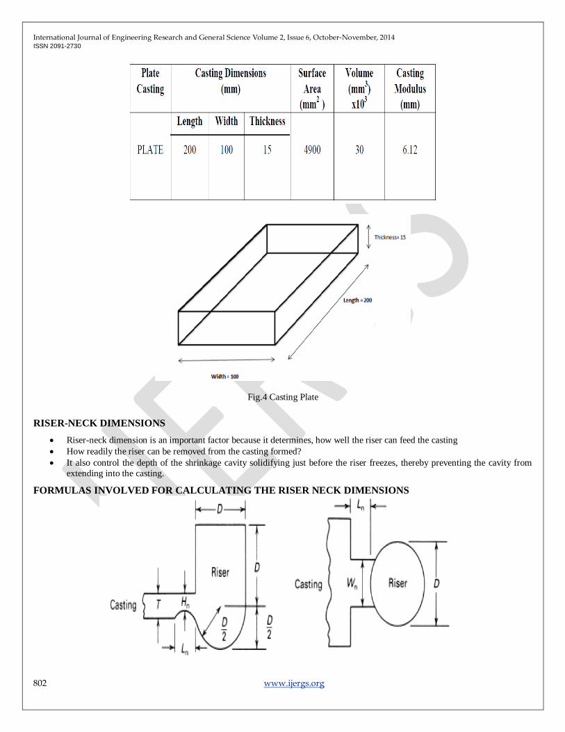
CASTING PLATE DIMENSIONS Table 2 Casting Plate Dimensions
International Journal of Engineering Research and General Science Volume 2, Issue 6, October-November, 2014 ISSN 2091-2730
802 www.ijergs.org
Fig.4 Casting Plate
RISER-NECK DIMENSIONS
Riser-neck dimension is an important factor because it determines, how well the riser can feed the casting
How readily the riser can be removed from the casting formed?
It also control the depth of the shrinkage cavity solidifying just before the riser freezes, thereby preventing the cavity from
extending into the casting.
FORMULAS INVOLVED FOR CALCULATING THE RISER NECK DIMENSIONS

International Journal of Engineering Research and General Science Volume 2, Issue 6, October-November, 2014 ISSN 2091-2730
803 www.ijergs.org
Figure 5 Riser Neck Dimensions (Side and Top View)
HN = (0.6 to 0.8) t
Max. LN = D/3
WN = 2.5 LN + 0.18 D
Where HN = Height of the gate, LN = Length of the gate, WN = width of the gate, D= diameter of riser, t= plate thickness [1].
CALCULATION OF RISER NECK DIMENSIONS a) Case (i)
Height of gate, HN1= 0.8*15 = 12 mm
Length of gate, LN1= 60/3 = 20mm
Width of gate, WN1 =2.5*20-0.18*60= 39.2mm
Similarly we can calculate the riser neck dimensions for rest of the cases.
THE BASIC REQUIREMENTS OF A FEEDER SYSTEM FOR A CASTING
Feeder must be thermally adequate
The solidification time of metal in feeder must be greater than the solidification time of metal in mould. So that it can feed enough
metal to the casting in order to compensate volume shrinkage during solidification. Therefore the shrinkage in the riser/casting system
must be concentrated in the riser, which can be removed from the finished casting [3]
According to Chvorinov’s equation,
Freeze time, t = K [V/SA]2
Where, t = freeze time of casting (sec)
V = volume of casting (mm3)
SA = surface area of casting (mm2)
K = solidification constant (sec/mm2)
Type of Riser Used
Open riser type for experimentation purpose. Since Open risers are exposed to the atmosphere and are easy to mould and also helps to
know whether the mould is completely filled or not.
RISER DESIGN According to Chvorinov‘s equation [3],
Solidification time (t) α [Volume / Surface Area] 2
It indicates that for a feeder to have a solidification time equal to or greater than that of the casting, the minimum feeder size would be
obtained from a sphere. Sphere are usually difficult to mould, and would present feeding problem as well, since the last metal to freeze
would be near the centre of the sphere, where it could not be used to feed a casting. Practicalities dictate the use of cylinders for most
risers. So the cylindrical riser with hemispherical base is used to provide the smallest possible surface area -volume ratio.
RISER DESIGN PARAMETERS The riser design involves the deciding of following parameters
Total volume of the riser which depends on the shrinkage characteristics of the metal and the shape of the casting etc.
The number of risers and their functions in relation to the casting.
The types, shape and size of the risers etc.

International Journal of Engineering Research and General Science Volume 2, Issue 6, October-November, 2014 ISSN 2091-2730
804 www.ijergs.org
CALCULATION OF RISER DIMENSIONS From Chvorinov‘s equation [3]
Solidification time (t) α [Volume / Surface Area] 2
i.e Using the modulus method , its empirical relation is
Mriser = 1.2 Mcasting…………… (1)
From casting plate dimensions, Mcasting = 6.12 mm
Therefore it can be used to calculate the value of Mriser using eq. (1)
i.e Mriser = 1.2*6.12
= 7.344 mm
Now let‘s take the volume and area of hemisphere:
-Volume of hemisphere= πd3/12
-Area of hemisphere = 3π (d/2)2
Modulus of riser, Mriser = volume/ area
Mriser = (πd3/12)
3π (d/2)2
Mriser = 0.11d……………… (2)
Equating equations (1) & (2),
7.314=0.11d
i.e d = 65mm (approx.)…………(a)
The ratio of height to diameter (h/d) varies from 1 to 1.5 for cylindrical risers [foundry rule].
Considering condition of h/d ratio =1.3
Therefore h=1.3d……………………… (b)
Now substituting equation (a) & (b),
i.e h= 1.3*65
h= 85mm (approx.)
Finally calculated riser dimension to design an optimum riser. Similarly assume the rest of the riser dimensions.
RISER DIMENSIONS
Table 3- Riser Dimensions

International Journal of Engineering Research and General Science Volume 2, Issue 6, October-November, 2014 ISSN 2091-2730
805 www.ijergs.org
A cylindrical riser with a hemispherical bottom is used in this project since the hemispherical bottom consumes 16-17% less metal
than the standard cylindrical side riser [16].
Figure 6- Feeder with Hemispherical Bottom
Thus dimensions of casting plates, riser & gates and are found.
COMPUTER SIMULATION In the past, the optimal casting design was achieved by trial and error method. Conventional method is time consuming and
ineffective, can no longer satisfies the needs of the foundry. This problem can be addressed with the use of computer aided
design/engineering technique.
Computer design and casting simulation have gradually become popular in recent years. With the help of the computer a number of
CAD/CAM commercial packages for the simulations of the casting have been developed and implemented in the foundry.
In this work, ANSYS 10.0 APDL version software has been used to find the optimum dimensions of the riser for rectangular plate FG
260 grey iron castings with cast iron end-chill. Solidification simulation process facilitates to visualize the temperature distribution in
various locations of the casting. Cooling curve obtained from simulation helps to find out the solidification time of casting and riser.
ASSUMPTIONS INCORPORATED It is difficult to incorporate all the environmental condition existing in the foundry; hence the following assumptions were
made during simulation.

International Journal of Engineering Research and General Science Volume 2, Issue 6, October-November, 2014 ISSN 2091-2730
806 www.ijergs.org
The mould is filled instantaneously and uniform temperature is assumed at all points of the casting and mould, at that instant.
Heat transfer by convection takes place to the atmosphere from the outer surface of the mould and top surface of riser and
runner.
The convective heat transfer within the liquid metal is neglected for sand moulds.
PREPROCESSING The pre-processing process contains the following commands to create a finite element model. They are as follows:
1. Defining Element and Options 2. Defining Element Real constants
3. Defining Material Properties
4. Creating Model Geometries
5. Defining Meshing controls
6. Applying Boundary conditions.
MODEL The model is created in solid works and it is saved in .iges format and then it is imported to ANSYS for the solution to
obtain.
Figure 7-Casting Model Imported into ANSYS Software in .iges Format
Once the model has been subjected to various boundary conditions ANSYS solves the set of equations generated by Finite Element
Model.
COMPUTER SIMULATION USING ANSYS The casting and mould assembly is modelled in the Pre-processor stage of simulation. One half of the casting and mould
assembly is modelled as it is symmetric. The convection takes place through all surfaces of sand except bottom surface. The mould is
assumed to be instantaneously filled with the molten metal at a pouring temperature of 1400oC.The mould outside surface is assumed
to be convection with film coefficient of 40oC because moisture in the sand will affect the cast metal. So, the sand is preheated up to
40oC.
a) Mould Material: Silica Sand
Density: 1580 x 10 –9 kg/mm3
Thermal conductivity: 0.393 x 10 –3 W/mm oC
Specific heat: 1046 J/kg oC
b) Initial Conditions: Casting temperature:1400o C

International Journal of Engineering Research and General Science Volume 2, Issue 6, October-November, 2014 ISSN 2091-2730
807 www.ijergs.org
Mould temperature: 40oC
Figure 8- Solution Obtained From ANSYS Software
c) Boundary Conditions:
Sand top surface convection: 3.48 W/m2 °K
Sand side surface convection: 4.09 W/m2 °K
CAST METAL: FG 260 GREY CAST IRON Table 4-Thermo Physical Properties of FG 260 Grey Cast Iron
RESULTS OBTAINED FROM COMPUTER SIMULATION Solidification simulation process facilitates to visualize the temperature distribution in various locations of the casting.
Cooling curve obtained from simulation helps to find out the solidification time of casting and riser and thereby the optimum result.
From the results obtained through ANSYS, cooling curves are constructed and temperature at different time for different configurations
is plotted in the graph. This is an indirect method of finding out the soundness of castings.
COOLING CURVES Cooling curves are obtained by plotting solidification time versus temperature. Cooling curve obtained from simulation helps
to find out the solidification time of casting and riser and thereby the optimum result. In this experiment, cooling curves are taken at
five different nodes on the casting placed namely from:
Top of the riser
International Journal of Engineering Research and General Science Volume 2, Issue 6, October-November, 2014 ISSN 2091-2730
808 www.ijergs.org
On the gating system
On the left side of plate
On the right side of plate
On the corner of the plate
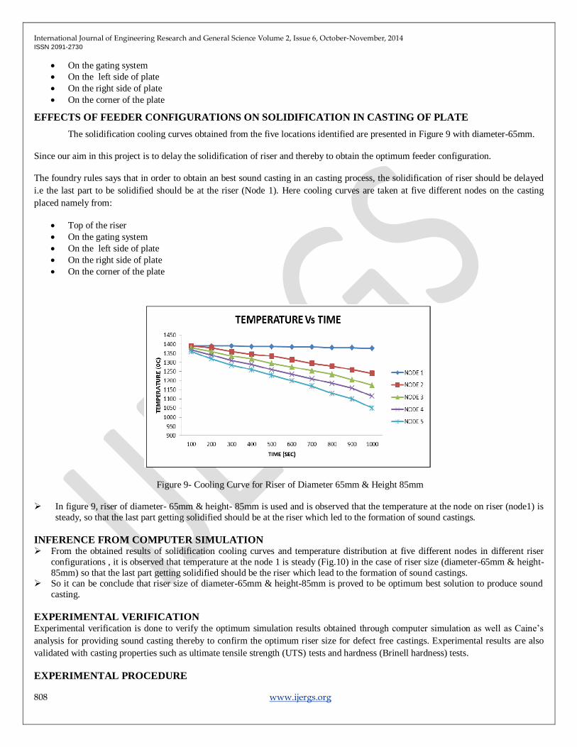
EFFECTS OF FEEDER CONFIGURATIONS ON SOLIDIFICATION IN CASTING OF PLATE
The solidification cooling curves obtained from the five locations identified are presented in Figure 9 with diameter-65mm.
Since our aim in this project is to delay the solidification of riser and thereby to obtain the optimum feeder configuration.
The foundry rules says that in order to obtain an best sound casting in an casting process, the solidification of riser should be delayed
i.e the last part to be solidified should be at the riser (Node 1). Here cooling curves are taken at five different nodes on the casting
placed namely from:
Top of the riser
On the gating system
On the left side of plate
On the right side of plate
On the corner of the plate
Figure 9- Cooling Curve for Riser of Diameter 65mm & Height 85mm
In figure 9, riser of diameter- 65mm & height- 85mm is used and is observed that the temperature at the node on riser (node1) is
steady, so that the last part getting solidified should be at the riser which led to the formation of sound castings.
INFERENCE FROM COMPUTER SIMULATION From the obtained results of solidification cooling curves and temperature distribution at five different nodes in different riser
configurations , it is observed that temperature at the node 1 is steady (Fig.10) in the case of riser size (diameter-65mm & height-
85mm) so that the last part getting solidified should be the riser which lead to the formation of sound castings. So it can be conclude that riser size of diameter-65mm & height-85mm is proved to be optimum best solution to produce sound
casting.
EXPERIMENTAL VERIFICATION Experimental verification is done to verify the optimum simulation results obtained through computer simulation as well as Caine‘s
analysis for providing sound casting thereby to confirm the optimum riser size for defect free castings. Experimental results are also
validated with casting properties such as ultimate tensile strength (UTS) tests and hardness (Brinell hardness) tests.
EXPERIMENTAL PROCEDURE

International Journal of Engineering Research and General Science Volume 2, Issue 6, October-November, 2014 ISSN 2091-2730
809 www.ijergs.org
A. MOULDING SAND
Silica sand moulds are prepared using sand mix with a composition of 8% calcium based bentonite, 5% moisture (approx.) and 2%
saw dust and coal powder are added.
B. MELTING AND POURING
The FG 260 Grey cast iron is melted in a crucible furnace. As soon as the molten metal reaches a temperature of 1400°C, it is taken
out and degassed using the required quantity of degassing tablets of ALDEGAS (Hexa Chloro Ethane) in order to remove the
dissolved hydrogen gas. At 1400°C, cooling and solidification takes place which result in evolution of gas bubbles, pinholes, and
microscopic porosity. Hence degassing is to be performed to minimize such defects [24].
C. CASTING EXPERIMENTAL SETUP
A standard rectangular plate casting size of 200 x 100 x 15 mm is selected as test casting for conducting the experiment. A wooden
pattern for the test casting and runner and cylindrical riser with hemispherical bottom of h/d ratio= 1.3 are made. Castings are
collected from the experiments, cut into small pieces and then checked for internal and external defects [16] & [24].
Figure 10-Cast Plate
TENSILE STRENGTH TEST SPECIMEN Tensile testing is carried out in the casting using an universal testing machine. The casting is made into a a tensile test
specimen in a conventional lathe. The ultimate tensile strength and hardness is determined experimentally. The standard tensile
specimen is prepared as shown in the Fig 11. The minimum ultimate tensile strength and hardness of each piece is determined in order
to categorise the castings whether sound or unsound.
Figure11- Dimensions of the Tensile Test Specimen

International Journal of Engineering Research and General Science Volume 2, Issue 6, October-November, 2014 ISSN 2091-2730
810 www.ijergs.org
Figure 12-Ultimate Tensile Strength Testing
HARDNESS TESTING In order to conduct the hardness test, the plate casting should be cleaned properly and then placed on the work piece holder
and undergoes Brinell hardness testing (BHN).
TENSILE AND HARDNESS TEST RESULTS
Table 5- Experimental Results Obtained
INFERENCE FROM EXPERIMENT The experimental results are compared with theoretical results for validation. It is observed that there is a closeness of
experimental values with the theoretical values .The optimal riser size of diameter-65mm and height-85mm produced a tensile
strength of 260 MPa and its corresponding hardness in the Brinell scale is 300BHN.
It is found that these optimal settings also produced sound casting which reveals the quality consciousness in the foundry.
ACKNOWLEDGMENT
First of all I should thank God almighty for blessing us with the wisdom to complete this work. I should also thank my
project guide Mr. Rathish R, Assistant Professor for his kind support and encouragement. Finally I should also thank my Department
staffs, parents and friends who always supported me in this work.
CONCLUSION
The optimal riser combination to produce sound casting for a standard rectangular plate (200mmx100mmx15mm) is determined as
diameter65mm and riser height-85mm with h/d =1.3 and riser with cylindrical bottom. The experimental results confirm the simulated
results obtained from ANSYS software. It is confirmed that the optimum riser combination promoted directional solidification which

International Journal of Engineering Research and General Science Volume 2, Issue 6, October-November, 2014 ISSN 2091-2730
811 www.ijergs.org
is responsible for casting soundness. The degree of solidification is obtained from the cooling curves from the ANSYS software.
Hence the cooling curve is an effective tool to predict the degree of solidification in any casting.
REFERENCES:
[1] ―Riser Design‖ Casting Design and Performance, ASM International, p.61–72.
[2] Dr. N K Srinivasan, ―Casting Introduction‖, Foundry Technology, 3rd Edition, p.1-5, 2012.
[3] Dr. N K Srinivasan, ―Riser Design‖, Foundry Technology, 3rd Edition, p.105-114, 2012
[4] R C Creese, ―Cylindrical Top Riser Designs Relationship for Evaluating Insulating Materials‖, AFS Transactions, Vol. 89, p.354
– 348, 1981.
[5] R C Creese, ―An Evaluation of Cylinder Riser Designs with Insulating Materials‖, AFS Transactions, Vol. 87, p. 665 –668, 1979.
[6] Piotr Mikolajczak, Zenon Ignaszak, ―Feeding Parameters for Ductile Iron in Solidification Simulation‖ p.5, 2007.
[7] R A Johns, ―Risering Steel Castings easily and efficiently‖, AFS Transactions, Vol.88, p-77- 96.
[8] E N Pan, C S Lin and C R Lopper, ―Effects of Solidification Parameters on the feeding efficiency of A356 Aluminum alloy‖,
AFS Transactions, Vol.98, p.135 –146,1990.
[9] Haider Hussain, Dr. A I Khandwawala, ―Optimal Design of Two Feeder System: Simulation Studies for Techno-Economic
Feasibility‖ American Journal of Mechanical Engineering, Vol. 2, No. 3, 93-98, 2014. [10] Prof. Karl B. Rundman, METAL CASTING, Reference Book for MY4130, 1986.
[11] John Campbell and Richard A. Harding, The Feeding of Castings, Training in Aluminum Application Technologies, (TALAT)
Lecture 3206, 1994.
[12] V V Mane, Amit Sata and M Y Khire, ―New Approach to Casting Defects Classification and Analysis Supported by Simulation‖.
[13] Rajesh Rajkolhe, J. G. Khan ―Defects, Causes and Their Remedies in Casting Process: A Review‖ International Journal of
Research in Advent Technology, (IJRAT) Vol.2, No.3, March 2014, E-ISSN: 2321-9637.
[14] Clyde Melvin Adams, Jr. ―Heat Flow in the solidification of Casting‖, 1953.
[15] Harshil Bhatt, Rakesh Barot, Kamlesh Bhatt, Hardik Beravala, Jay Shah, ―Design Optimization of Feeding System and
Solidification Simulation for Cast Iron‖, Procedia Technology 14 ( 2014 ) 357 – 364,Science Direct, ICIAME 2014 .
[16] V Gopinath, N Balanarasimman, ―Effect of Solidification Parameters on the Feeding Efficiency of Lm6 Aluminum Alloy
Casting‖, Journal of Mechanical and Civil Engineering, (IOSR-JMCE), Volume 4, Issue 2, p.32-38, Dec. 2012R C Creese, ―An
Evaluation of Cylinder Riser Designs with Insulating Materials‖, AFS Transactions, Vol. 87, p. 665 –668, 1979.
[17] Dr. B. Ravi, ―Computer-Aided Casting Design –Past, Present and Future‖, Indian Foundry Journal, 2010. Durgesh Joshi, ―10-
year Survey of Computer Applications in Indian Foundry Industry‖ Indian Foundry Journal, January 2010.
[18] Durgesh Joshi, ―10-year Survey of Computer Applications in Indian Foundry Industry‖ Indian Foundry Journal, January 2010.
[19] Clyde Melvin Adams, Jr. ―Heat Flow in the solidification of Casting‖, 1953.
[20] R A Johns, ―Risering Steel Castings easily and efficiently‖, AFS Transactions, Vol.88, p-77- 96.
[21] Indian Standard Grey Iron Castings - IS 210 :( superseding is 6331: 1987) – Specification -Bureau of Indian Standards (BIS) -
fifth revision-2009. [22] Nimesh A Khirsariya, M S Kagthara , P J Mandalia, ―Reduction of Shrinkage Defect in Valve Body Casting Using Simulation
Software” ,International Journal Of Engineering Science & research Technology (IJESRT), April,2014,ISSN:2277-96551.
[23] P J. Mandaliya , J T Dave ―Study of Piston Sleeve Manufactured By Sand Casting Process to
Reduce Rejection Rate Using Simulation Software‖, International Journal of Mechanical and Production Engineering Research
And Development (IJMPERD) ISSN 2249-6890 Vol. 3, Issue 2, Jun 2013, 161-168.
[24] Pouring, Cooling, Shakeout, Iron, Step Core, Beach Box® Binder, Comparison to Test GZ 1412-116 HD, Casting Emission
Reduction Program (CERP), US Army Contract W15QKN-05-D-0030, November 2006.
[25] ME355 Winter 2014 – Introduction to Manufacturing Processes HW #3 solutions – 1/31/2014.
[26] Metal Casting Process, Qualitative Problems, Chapter 11