SIMULATING THE RUBBLE MOUND UNDERLYING ARMOUR …
9
Seventh South African Conference on Computational and Applied Mechanics SACAM10 Pretoria, 10-13 January 2010 c SACAM SIMULATING THE RUBBLE MOUND UNDERLYING ARMOUR UNITS PROTECTING A BREAKWATER Antony K Cooper *,1 , Rosalie de Villiers *,2 , Jan M Greben *,3 , Frans van den Bergh †,4 and Irvy MA Gledhill ‡,5 * Built Environment Unit † Meraka Institute ‡ Defence, Peace, Safety and Security Unit CSIR, PO Box 395, Pretoria, 0001, South Africa 1 [email protected], 2 [email protected], 3 [email protected], 4 [email protected], 5 [email protected]. Keywords: Breakwater, Rubble, Rubble mound, Armour unit, Physics engine, Height field. Abstract A variety of concrete armour units laid on top of rubble mounds are used to protect break- waters and other harbour infrastructure. Coastal engineers build three-dimensional physical scale models to understand the dynamic processes caused by seas on such infrastructure. We are developing analytical techniques for understanding breakwater structural stability. We are modelling the infrastructure using a physics engine, which handles the rigid body mechanics. We report here on our attempts to model the rubble mounds underlying the armour units. In its most primitive form, we model the rubble as a static structure with flat surfaces and then pack the selected armour units on top. This reduces the complexity, but the porosity of the packing close to the rubble is much higher than it would be in practice, because of the lack of inter-penetration between the rubble and the armour layer. Further, the armour units slide easily on the flat surface, making it difficult to simulate a realistic packing. The two approaches to solve this problem that are discussed here are the height field and modelling individual rubble units. The height field is a rigid, square mesh with random heights distributed uniformly. It is com- putationally cheap to implement and largely solves the porosity and related problems, but it is rigid, so it cannot change shape to respond to movements by the armour units or the water. Modelling individual rubble units is computationally expensive, because of the number of ob- jects required and their potential complexity. Currently, we have modelled the rubble using a simple sphere-like polyhedron, and have been able to model a very large packing of them.
Transcript of SIMULATING THE RUBBLE MOUND UNDERLYING ARMOUR …

Seventh South African Conference on Computational and Applied MechanicsSACAM10
Pretoria, 10−13 January 2010c©SACAM
SIMULATING THE RUBBLE MOUND UNDERLYING ARMOURUNITS PROTECTING A BREAKWATER
Antony K Cooper ∗,1, Rosalie de Villiers ∗,2, Jan M Greben ∗,3, Frans van den Bergh †,4
and Irvy MA Gledhill ‡,5
∗Built Environment Unit†Meraka Institute
‡Defence, Peace, Safety and Security UnitCSIR, PO Box 395, Pretoria, 0001, South Africa
[email protected], [email protected], [email protected],[email protected], [email protected].
Keywords: Breakwater, Rubble, Rubble mound, Armour unit, Physics engine, Height field.
Abstract
A variety of concrete armour units laid on top of rubble mounds are used to protect break-waters and other harbour infrastructure. Coastal engineers build three-dimensional physicalscale models to understand the dynamic processes caused by seas on such infrastructure. Weare developing analytical techniques for understanding breakwater structural stability. We aremodelling the infrastructure using a physics engine, which handles the rigid body mechanics.We report here on our attempts to model the rubble mounds underlying the armour units.
In its most primitive form, we model the rubble as a static structure with flat surfaces and thenpack the selected armour units on top. This reduces the complexity, but the porosity of thepacking close to the rubble is much higher than it would be in practice, because of the lack ofinter-penetration between the rubble and the armour layer. Further, the armour units slide easilyon the flat surface, making it difficult to simulate a realistic packing. The two approaches tosolve this problem that are discussed here are the height field and modelling individual rubbleunits.
The height field is a rigid, square mesh with random heights distributed uniformly. It is com-putationally cheap to implement and largely solves the porosity and related problems, but itis rigid, so it cannot change shape to respond to movements by the armour units or the water.Modelling individual rubble units is computationally expensive, because of the number of ob-jects required and their potential complexity. Currently, we have modelled the rubble using asimple sphere-like polyhedron, and have been able to model a very large packing of them.

1 Introduction
1.1 Project background
A variety of concrete armour units (such as dolosse) laid on top of rubble mounds are used toprotect breakwaters, piers and other harbour infrastructure, serving both to absorb the impactof violent seas and to reduce overtopping (heavy seas flowing over harbour defences into thesupposedly protected areas of harbours). Breakwaters can be built entirely of rubble, but it isexpensive to get sufficient quantities of rocks large enough to withstand heavy seas. Armourunits are cheaper, can be built in situ and have various design characteristics that enhance theirfunctionality [1]. Coastal engineers build three-dimensional physical scale models of actual orplanned harbours (as shown in Figure 1), in order to understand the dynamic processes causedby waves, tides, currents and storms. However, these models are expensive and time-consumingto build, while the effects of downscaling affect their predictive ability [2].
Figure 1: CSIR’s physical model hall [2].
We are engaged in a wide-ranging project aimed at developing analytical techniques for appli-cation to breakwater structural stability and the development of associated numerical simula-tion and modelling technology, including the modelling of waves and using photogrammetryto record changes in breakwater structures [3, 2, 4, 5, 6, 7, 8, 9]. Various approaches are beingfollowed and the ultimate goal is to integrate these into an advanced numerical analysis toolsupplementing and exploiting the physical models [3, 7].
1.2 Physics engine
We are modelling the physical infrastructure of breakwaters using a physics engine, PhysX[10], which handles the rigid body mechanics. Physics engines were developed for computergames to provide realistic visual simulations of the real world, allowing one to set parameterssuch as for gravity, and the coefficients of restitution, linear and angular damping, and static and
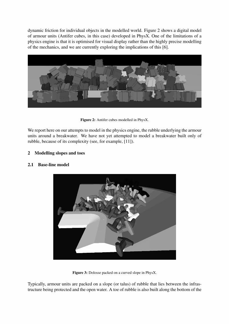
dynamic friction for individual objects in the modelled world. Figure 2 shows a digital modelof armour units (Antifer cubes, in this case) developed in PhysX. One of the limitations of aphysics engine is that it is optimised for visual display rather than the highly precise modellingof the mechanics, and we are currently exploring the implications of this [6].
Figure 2: Antifer cubes modelled in PhysX.
We report here on our attempts to model in the physics engine, the rubble underlying the armourunits around a breakwater. We have not yet attempted to model a breakwater built only ofrubble, because of its complexity (see, for example, [11]).
2 Modelling slopes and toes
2.1 Base-line model
Figure 3: Dolosse packed on a curved slope in PhysX.
Typically, armour units are packed on a slope (or talus) of rubble that lies between the infras-tructure being protected and the open water. A toe of rubble is also built along the bottom of the

slope to support the armour units and to influence where the incoming waves will break. Thedesigner of the breakwater determines the characteristics such as the shape, angle and heightof the slope, the size and shape of the toe, and the size of the rubble used (typically, varyingthrough the rubble layer, from smaller rubble in the core to larger rubble in the outer layer).The designer of the breakwater prepares a placing grid, which specifies where each armourunit should be placed under ideal conditions, whether by the packer in the model hall (modelscale) or by the crane operator in the field (prototype scale) [1]. Similarly in the PhysX model,we lower the armour units one by one into their positions on the breakwater, where they arereleased to settle under gravity on the rubble mound and/or other armour units.
For the base-line model, we represent the underlying infrastructure (the slope and toe) as arigid structure with smooth surfaces and then pack the selected armour units on top of this.This reduces the complexity of the model and facilitates understanding the process of packingthe armour units on top of the slope. The model currently allows the slope to curve arbitrarily,as required (as shown in Figure 3) [5].
However, a problem with using a smooth surface for the rubble layer is that the porosity of thepacking close to the surface in the physics engine is higher than it would be in practice, becauseof the lack of inter-penetration of the boundaries of the rubble mound and armour layer. This isillustrated by the graph in Figure 4, which shows how the void fraction varies through a samplepacking of dolosse in PhysX. As can be seen, the void fraction is close to 1 close to the surface.While it might be useful to validate the void fraction of the numerical model against that of aphysical model, we are not yet able to produce a numerical model that is an exact replica of aphysical model, save for trivial cases.
Figure 4: Void fractions for dolosse packed on a smooth slope.
A key problem with this is that when fluids are introduced to the structure, excessive chan-nelling could occur along the boundary because the fluid velocity is likely to be higher there[12]. This is likely to lead to the incorrect artifact of increased scour along the boundary in themodel between the rubble layer and the armour units, and increased hydrodynamic forces onthe armour units.
Further, placing armour units on a smooth slope can generate an unrealistic packing, becausethe armour units slide down too easily when placed on the smooth surface, as we have foundin our experiments. We have tried tempering this by increasing the static and dynamic frictionof the slope, but the friction needs to be very high to take effect. While that might produce amore accurate packing ab initio, it is likely to distort the movement of the armour units (or lackthereof) when subjected to the forces simulating waves and other fluid dynamics, as the muchhigher friction will requirer higher forces to move the armour units.
One approach to simulating the rubble layer could be to vary randomly the parameters foreach armour unit when they are packed. While this might provide a more realistic packing ofthe armour units, it will not deal with the porosity, channelling and scouring problems at theboundary with the slope, as discussed above. Hence, we have not attempted this method. Thetwo approaches that we have implemented are the height field and modelling individual rubbleunits, as discussed below.
2.2 Height field
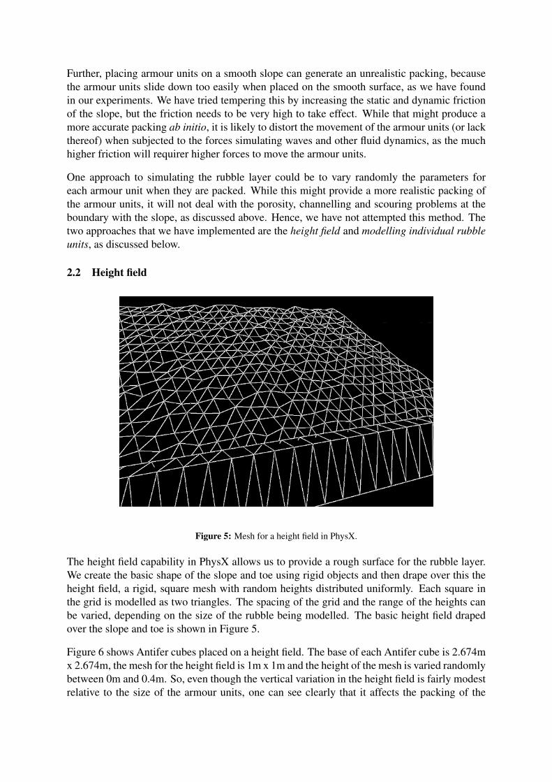
Figure 5: Mesh for a height field in PhysX.
The height field capability in PhysX allows us to provide a rough surface for the rubble layer.We create the basic shape of the slope and toe using rigid objects and then drape over this theheight field, a rigid, square mesh with random heights distributed uniformly. Each square inthe grid is modelled as two triangles. The spacing of the grid and the range of the heights canbe varied, depending on the size of the rubble being modelled. The basic height field drapedover the slope and toe is shown in Figure 5.
Figure 6 shows Antifer cubes placed on a height field. The base of each Antifer cube is 2.674mx 2.674m, the mesh for the height field is 1m x 1m and the height of the mesh is varied randomlybetween 0m and 0.4m. So, even though the vertical variation in the height field is fairly modestrelative to the size of the armour units, one can see clearly that it affects the packing of the

Antifer cubes, as is planned. Figure 7 shows dolosse (of a similar size to the Antifer cubesshown in Figure 6) placed on a height field, where the height is more pronounced (varyingrandomly between 0m and 0.9m), and showing the inter-penetration of the rubble layer withthe dolos layer. The height field is translucent, which is why one can see the shadows of thedolosse underneath it.
Figure 6: Antifers placed on a height field simulating rubble.
Figure 7: Dolosse placed on a height field simulating rubble.
The height field is computationally cheap to implement and largely addresses the porosity,channelling and scouring problems of the smooth surface by ensuring inter-penetration of the

boundaries of the rubble mound and armour layer. However, the height field is rigid, whichmeans that it cannot change shape to respond to movements by the armour units or by thewater. We are also currently exploring if the orientation of the triangles introduces a systematicbias into the height field and, more importantly, into the packing of the armour units on top ofthe height field.
2.3 Modelling individual rubble units
Modelling individual rubble units is computationally very expensive, because of the numberof objects required. The rubble is also not uniform in practice (for both prototype and modelscale), varying both in shape and size. It is difficult and tedious to model a wide variety ofrubble shapes [11], but we are exploring techniques for generating these automatically. Forexample, our colleagues in road engineering are producing accurate three-dimensional modelsof pieces of aggregate used for road building (the same technique used by [11] to producesample rubble units), and we are exploring with them the possibility of using their models tosimulate rocks in our models.
Currently, we have modelled the rubble using a sphere-like polyhedron. We have been able tooptimise the software to produce a very large packing of these simple polyhedra on a standardpersonal computer, with over 6400 in the model shown in Figure 8. The next step will be toadd armour units on top of the rubble layer. We are exploring if using one shape but varyingits size will produce suitable rubble, or if we need a greater variety of shapes as well. As [11]have done, we will also explore the extent to which each shape used can be simplified. It mightalso be necessary to use hardware acceleration, which is provided directly for PhysX by somegraphics cards [10].
Figure 8: Rubble simulated in PhysX with sphere-like polyhedra.
3 Conclusion
We have reported here on two methods that we have developed to try to produce realistic mod-els in a physics engine, of the rubble mounds underlying the concrete armour units laid to

protect breakwaters and other harbour infrastructure. The key issue is dealing with the inter-face between the rubble mound and the armour layer, which should inter-penetrate one anotherto provide accurate porosity there, to prevent channelling and scouring problems in the model.The rubble mound should also be flexible to accommodate movements by the armour units andthe water.
The two approaches to solve this problem that are discussed here are the height field and mod-elling individual rubble units. The height field is a rigid, square mesh with random heightsdistributed uniformly. It is computationally cheap to implement and largely solves the porosityand related problems, but it is rigid, so it cannot change shape to respond to movements bythe armour units or the water. Modelling individual rubble units is computationally expensive,because of the number of objects required and their potential complexity. Currently, we havemodelled the rubble using a simple sphere-like polyhedron, and have been able to model a verylarge packing of them.
We are exploring techniques to improve the accuracy of the models using the height field andunderstanding how to model individual rubble units effectively. We are also exploring thepossibility of combining the two techniques, using the height field to model the core of therubble mound that is static, and then packing the outer layers of individual rubble units on topof the height field. At this conference, we have also reported on our work on calibrating thephysical models [6], calibrating the fluids models [9], and integrating the models [7].
We wish to acknowledge the support of the CSIRs Strategic Research Panel (SRP), for fundingthis work through projects PP TH 2006 044 and TA 2008 027, and for enabling us to makethis presentation. We also wish to acknowledge the support of the CSIR’s Coastal EngineeringGroup in Stellenbosch, for making their facilities available for us and for tolerating our naıvequestions.
References
[1] A.B. Frens. The impact of placement method on Antifer-block stability. Master’s thesis,Technical University of Delft, Delft, The Netherlands, May 2007.
[2] A.K. Cooper, J.M. Greben, F. Van der Bergh, I.M.A. Gledhill, B.R. Cannoo, W.J.vdM.Steyn, and R. De Villiers. A preliminary physics-engine model of dolosse interacting withone another. In B.D. Reddy, editor, Sixth South African Conference on Computationaland Applied Mechanics (SACAM08), Cape Town, South Africa, 27 March 2008. SouthAfrican Association for Theoretical and Applied Mechanics (SAAM).
[3] B.R. Cannoo, I.M.A. Gledhill, A.K. Cooper, and J.M. Greben. Navier-Stokes wave mod-els for investigations of breakwater characteristics. In B.D. Reddy, editor, Sixth SouthAfrican Conference on Computational and Applied Mechanics (SACAM08), pages 127–134, Cape Town, South Africa, 27 March 2008. South African Association for Theoreticaland Applied Mechanics (SAAM).
[4] I.M.A. Gledhill, A.K. Cooper, J.M. Greben, J.-H. Grobler, and R. De Villiers. Dolos ar-mour units and the modelling of coastal breakwaters. In 1st African Conference on Com-putational Mechanics — An International Conference (AfriCOMP 2009), Sun City, SouthAfrica, 8 January 2009. European Community on Computational Methods in Applied Sci-ences (ECCOMAS), International Association on Computational Mechanics (IACM) andSouth African Association for Theoretical and Applied Mechanics (SAAM).

[5] J.M. Greben, A.K. Cooper, I.M.A. Gledhill, and R. De Villiers. Numerical modelling ofstructures of dolosse and their interaction with waves. In 2nd CSIR Biennial Conference:Science Real and Relevant, Pretoria, South Africa, 17–18 November 2008. CSIR.
[6] J.M. Greben, A.K. Cooper, R. De Villiers, I.M.A. Gledhill, and F. Van den Bergh. Char-acterization and properties of breakwater structures modelled by a physics engine. In Sev-enth South African Conference on Computational and Applied Mechanics (SACAM10),Pretoria, South Africa, 10–13 January 2010.
[7] J.-H. Grobler, R. De Villiers, and A.K. Cooper. Modelling of fluid-solid interaction us-ing two stand-alone codes. In Seventh South African Conference on Computational andApplied Mechanics (SACAM10), Pretoria, South Africa, 10–13 January 2010.
[8] R. Vieira, F. Van Den Bergh, and B.J. Van Wyk. Fiducial-based monocular 3D displace-ment measurement of breakwater armour unit models. In F. Nicolls, editor, NineteenthAnnual Symposium of the Pattern Recognition Association of South Africa (PRASA 2008),pages 97–102, Cape Town, South Africa, 27–28 November 2008. Pattern Recognition As-sociation of South Africa (PRASA).
[9] R. Mukaro, K. Govender, I.M.A. Gledhill, and N.L. Kokwe. Velocity flow field and waterlevel measurements in shoaling and breaking water waves. In Seventh South African Con-ference on Computational and Applied Mechanics (SACAM10), Pretoria, South Africa,10–13 January 2010.
[10] NVIDIA. NVIDIA R© PhysXTM Technology web page, 2009.[11] J.-P. Latham and A. Munjiza. The modelling of particle systems with real shapes. Philo-
sophical Transactions of the Royal Society A, 362:1953–1972, 2004.[12] S.M. White and C.L. Tien. Analysis of flow channeling near the wall in packed beds.
Warme- und Stoffubertragung, 21:291–296, 1987.