Simrad RI9 Rudder Angle Indicator - Echomaster Marine Ltd. · Angle Indicator to an AP50 system...
34
Simrad RI9 Rudder Angle Indicator INSTRUCTION MANUAL
Transcript of Simrad RI9 Rudder Angle Indicator - Echomaster Marine Ltd. · Angle Indicator to an AP50 system...

Simrad RI9 Rudder Angle Indicator
INSTRUCTION MANUAL

2 20220562D
Note!
Simrad AS makes every effort to ensure that the information contained within this document is correct. However, our equipment is continuously being improved and updated, so we cannot assume liability for any errors which may occur.
Warning!
The equipment to which this manual applies must only be used for the purpose for which it was designed. Improper use or maintenance may cause damage to the equipment or injury to personnel. The user must be familiar with the contents of the appropriate manuals before attempting to operate or work on the equipment.
Simrad AS disclaims any responsibility for damage or injury caused by improper installation, use or maintenance of the equipment.
Copyright
© 2004 Simrad AS
The information contained within this document remains the sole property of Simrad AS.
No part of this document may be copied or reproduced in any form or by any means, and the information contained within is not to be communicated to a third party, without the prior written consent of Simrad AS.
Instruction Manual
20220562D 1
Instruction Manual This manual is intended as a reference guide for operating and correctly installing the RI9 Rudder Angle Indicator.
Please take time to read the manual to get a thorough understanding of the indicator system and its relationship to a complete autopilot system.
Other documentation materials that are provided with your system include a warranty card. This must be filled out by the authorized dealer that performed the installation and mailed in to activate the warranty.
Document revisions
Rev Date Written by Checked by Approved by
– 09.09.97 N.G. I.K. Th.H.
A 24.09.97 N.G. Th.H.
B 21.10.97 N.G. Th.H.
C 29.11.00 N.G. TJ Th.H.
D 30.06.04
Document history
Rev. – First edition
Rev. A Approved revision of Fig. 1-8 and 1-9 included.
Rev. B Operating temperature, page 3, corrected.
Rev. C Connection diagram for Panorama Mk2 included. RF45X included.
Rev. D Part number for RI9 PCB Ass’y corrected, page 10. New transmission rod for RF45X. Connection to AP50 system.

Simrad RI9 Rudder Angle Indicator
2 20220562D
Contents 1 RI9 RUDDER ANGLE INDICATOR..................................................................3
1.1 General............................................................................................................3 1.2 Technical specifications .................................................................................3 1.3 Installation ......................................................................................................4
Stand alone rudder angle indicator(s).............................................................5 Connection to autopilot junction units ...........................................................6 RI9 set-up .......................................................................................................9
1.4 Maintenance..................................................................................................12 1.5 Spare parts ....................................................................................................12
2 RF14XU RUDDER FEEDBACK UNIT ............................................................13 2.1 General..........................................................................................................13 2.2 Technical specifications ...............................................................................14 2.3 Installation ....................................................................................................15 2.4 Wiring ...........................................................................................................15 2.5 Other rudder angles ......................................................................................23 2.6 Adjustments ..................................................................................................24 2.7 Spare parts ....................................................................................................24
3 RF45X RUDDER FEEDBACK UNIT ...............................................................25 3.1 General..........................................................................................................25 3.2 Technical specifications ...............................................................................25 3.3 Mounting ......................................................................................................26 3.4 Electrical connection ....................................................................................28 3.5 Spare parts ....................................................................................................31

Instruction Manual
20220562D 3
1 RI9 RUDDER ANGLE INDICATOR
1.1 General The RI9 is manufactured in non-corrosive aluminum with a non-reflective black finish.
It is designed to operate from both voltage and current signals. The RI9 can also operate from the earlier Robertson "Standard" rudder feedback units.
The indicator is made in standard modular size (144x144 mm) to match the standard of the Simrad autopilots.
A separate PCB is mounted inside the indicator to convert the input signals for the indicator instrument. To select either voltage or current operation, a “jumper” is plugged in the respective position. For voltage operation a jumper is available for inverting the feedback signal.
The instrument gives a continuous reading of the rudder angle up to 45 degrees on either side of the midship’s position. (Other angles as optional). Both deflection and offset are adjustable on the PCB. Internal illumination can be adjusted by the dimmer control on the front.
The water tight construction allows bulkhead or desk mounting in exposed locations, such as bridge wings as well as wheelhouse and engine room.
RI9 substitutes the Robertson RI40 and RI45 rudder angle indicators.
1.2 Technical specifications Dimensions:.............................................See Fig. 1-1 Voltage supply:........................................ 12/24V DC +/-20% Current consumption:.............................. 100mA Input signal: .............................................Voltage (0-18V) or current (0.1 - 1.1mA) Reverse meter deflection:........................On voltage input signal Operating temperature:............................ –10°C to +55°C Protection:................................................ IP56 Safe distance to magnetic compass:........ 2.6m (9 ft) Rudder Feedback Units:..........................RF14XU, RF14XI,
RF45/RF45X, RF100, RF140, “Mini” and “Standard” Rudder Potentiometer.

Simrad RI9 Rudder Angle Indicator
4 20220562D
137
(5.4
0")
144
(5.6
7")
Panel cut-out:138x138 (5.44")65 (2.56")
57 (2.24")
144 (5.67")
153
(6.0
2")
RI9
Fig. 1-1 RI9 Dimensions
1.3 Installation The RI9 is designed for bulkhead or panel mounting, and should be positioned in a location in clear view of the helmsman and the ship's officers. For bulkhead mounting, use the 8 bushings enclosed with the unit. These are placed two and two against each other and the screws are put through them. Direct contact between RI9 and a steel bulkhead is then avoided and corrosion is prevented.
Several indicators may be connected to one rudder feedback unit, in parallel for voltage input signal, and in series for current input signal.
Fig. 1-2 RI9 Panel mounting

Instruction Manual
20220562D 5
Fig. 1-3 RI9 Bulkhead mounting
Stand alone rudder angle indicator(s)
The RI9 indicator can be used in stand alone rudder angle indicator systems as described in sections 2 and 3 of this manual or as part of an autopilot system as described below.

Simrad RI9 Rudder Angle Indicator
6 20220562D
Connection to autopilot junction units
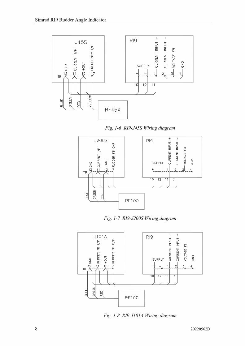
All interconnection cables should be screened, 1.5 mm2 (AWG14) wires. See Fig. 1-4 to Fig. 1-9 for connections to the different autopilot junction units.
Fig. 1-4 RI9 in an AP50 system with RF45X
The above connection diagram shows how to connect an RI9 Rudder Angle Indicator to an AP50 system with RF45X Rudder Feedback Unit.
This connection gives full functioning indicator(s) also with the autopilot switched off. To have the indicator(s) switched off with the autopilot, connect indicator(s) and rudder feedback supply+ to J50 Vbat+ instead of J50 Supply+.
Note ! The resistor R (0.5-1K, 0.5W) has to be mounted. The resistor is not supplied by Simrad.

Instruction Manual
20220562D 7
Fig. 1-5 RI9 in a AP50 system with RF14XU
The above connection diagram shows how to connect an RI9 Rudder Angle Indicator to an AP50 system with RF14XU Rudder Feedback Unit.
Notes ! This configuration is for 24VDC only.
The resistor R (0.5-1K, 0.5W) has to be mounted. The resistor is not supplied by Simrad.
The RI9 Rudder Angle Indicator is connected to the U-terminal on RF14XU.
The connection shown above gives full functioning indicator(s) also with the autopilot switched off. To have the indicator(s) switched off with the autopilot, connect indicator(s) and rudder feedback supply+ to J50 Vbat+ instead of J50 Supply+.
Simrad RI9 Rudder Angle Indicator
8 20220562D
Fig. 1-6 RI9-J45S Wiring diagram
Fig. 1-7 RI9-J200S Wiring diagram
Fig. 1-8 RI9-J101A Wiring diagram

Instruction Manual
20220562D 9
Fig. 1-9 RI9-J45A Wiring diagram
RI9 set-up
The RI9 indicator is calibrated for voltage input signal (RF14XU Rudder Feedback Unit). Assuming that the mechanical linkage is in accordance with the instruction on Fig. 2-2 adjustment of the trimpotmeters marked Voltage FB, G (=Gain) and O (= Offset) is not necessary.
If the RI9 is indicating wrong/opposite direction, the meter deflection can be reversed by moving “jumper” ST1 from “Norm” to “Inv”.
Note ! The “Norm”/“Inv” jumper does not affect the meter deflection for current input signal. If the meter deflection has to be reversed, it must be made in the feedback unit as described for RF45 and RF14XI.
If the current input signal is used (RF100, RF140, RF14XI, RF45), the reference inside RI9 has to be changed. This is done by opening the RI9 and move the “jumper” ST3 from “U” to “I” position (see Fig. 1-10).

Simrad RI9 Rudder Angle Indicator
10 20220562D
Fig. 1-10. RI9 Input signal selection
Note ! When changing from voltage to current signal (or vice versa), the indicator may have to be recalibrated. In this case, or if the Gain and Offset trimpot’s for other reasons are maladjusted, the following calibration procedure should be carried out:
1. Take the rudder to midship position.
2. Use trimpot “O” (Offset) to calibrate RI9 to indicate zero rudder angle.
3. Move the rudder to e.g. 40 degrees (starboard or port). Use trimpot “G” (Gain) to calibrate RI9 to show the same angle as the rudder is set to (or the same angle as shown on the autopilot display in “Debug” mode).
Instruction Manual
20220562D 11
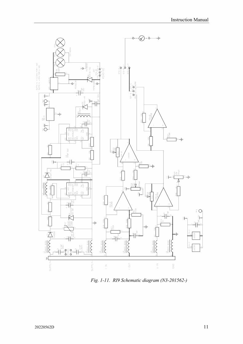
Fig. 1-11. RI9 Schematic diagram (N3-201562-)
Simrad RI9 Rudder Angle Indicator
12 20220562D
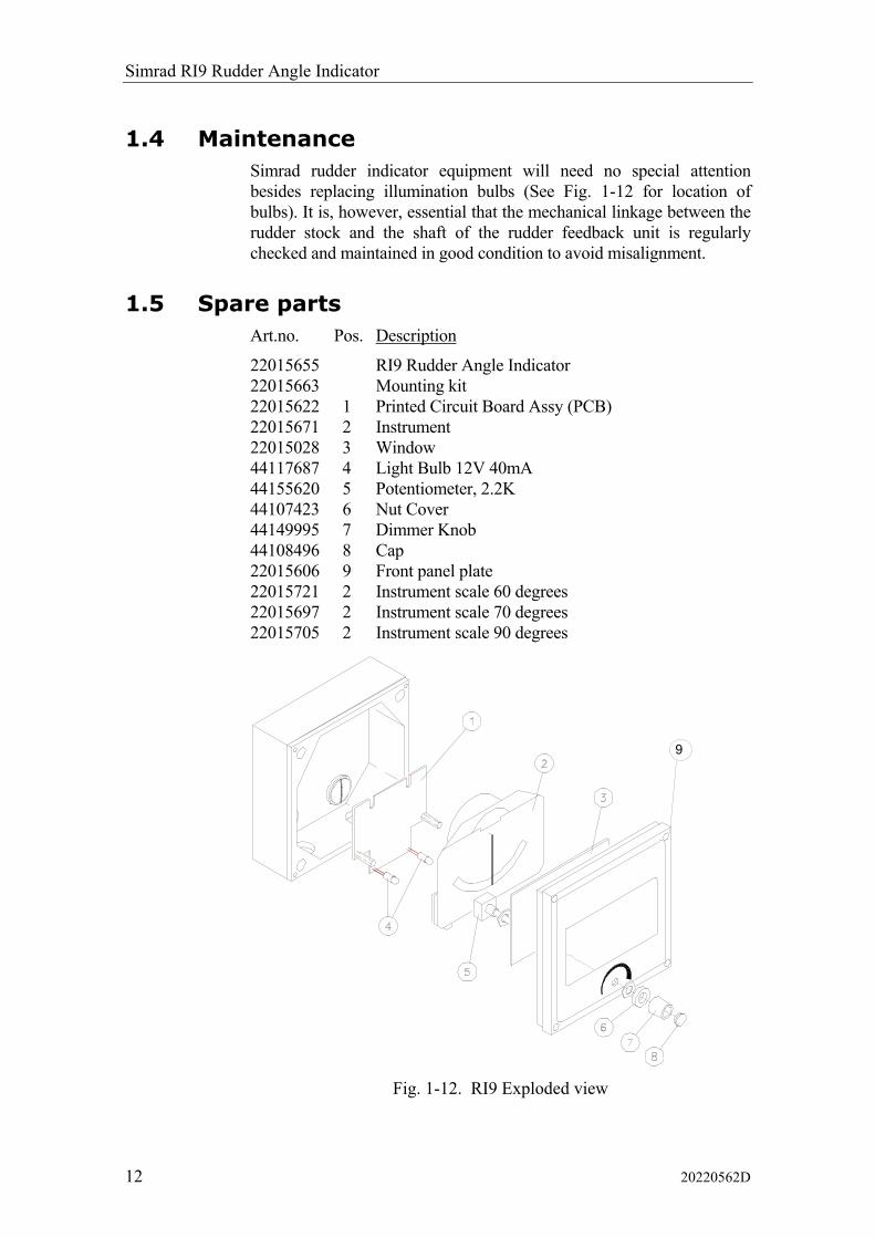
1.4 Maintenance Simrad rudder indicator equipment will need no special attention besides replacing illumination bulbs (See Fig. 1-12 for location of bulbs). It is, however, essential that the mechanical linkage between the rudder stock and the shaft of the rudder feedback unit is regularly checked and maintained in good condition to avoid misalignment.
1.5 Spare parts Art.no. Pos. Description
22015655 RI9 Rudder Angle Indicator 22015663 Mounting kit 22015622 1 Printed Circuit Board Assy (PCB) 22015671 2 Instrument 22015028 3 Window 44117687 4 Light Bulb 12V 40mA 44155620 5 Potentiometer, 2.2K 44107423 6 Nut Cover 44149995 7 Dimmer Knob 44108496 8 Cap 22015606 9 Front panel plate 22015721 2 Instrument scale 60 degrees 22015697 2 Instrument scale 70 degrees 22015705 2 Instrument scale 90 degrees
Fig. 1-12. RI9 Exploded view
9

Instruction manual
20220562D 13
2 RF14XU RUDDER FEEDBACK UNIT
2.1 General The rudder feedback unit transmits a signal proportional to the rudder angle. It is mounted close to the rudder stock and is mechanically connected to the rudder by a transmission link in a 1:1 ratio.
The RF14XU Rudder Feedback Unit consists of a glass-reinforced non-flammable polyester housing with a mounting plate of sea-water resistant aluminium. It contains a potentiometer, limit switches and an electronic drive module. The electronic drive module contains a voltage section and a frequency section.
The voltage section outputs a voltage to the rudder angle indicator(s) which is proportional to the rudder angle. The voltage varies ±9 volts around half the supply voltage.
The frequency section generates a variable frequency signal with 3400 Hz as midposition reference. This section is only used if a Simrad autopilot is connected to RF14XU. The signal varies at a rate of 20 Hz/degree, increasing when the rudder moves to port and vice versa.
The shaft of the Feedback Unit is free to travel 360 degrees, but only ±90 degrees from midposition are used for signal control.
RF14XU is equipped with two sets of micro switches, which can be used as electrical limit switches for the steering gear.

Simrad RI9 Rudder Angle Indicator
14 20220562D
2.2 Technical specifications Dimensions:............ .........See Fig. 2-1 and Fig. 3-2 Protection: .............. .........IP56 Ambient temperature:.......–10 - +55°C Supply voltage:....... .........24VDC –10%/20% Frequency section 12-40V DC Output RAI:............ .........Midship reference 0.5 x supply voltage Full deflection ±9V Output autopilot: 3400Hz ±20Hz/degree No. of indicators: 5 in parallel Rudder angle: ......... .........±45° (changeable to 60, 70 or 90°) Limit switches: ....... .........Adjustable from ±5° to ±160°
Fig. 2-1 RF14XU, dimensions
Instruction manual
20220562D 15
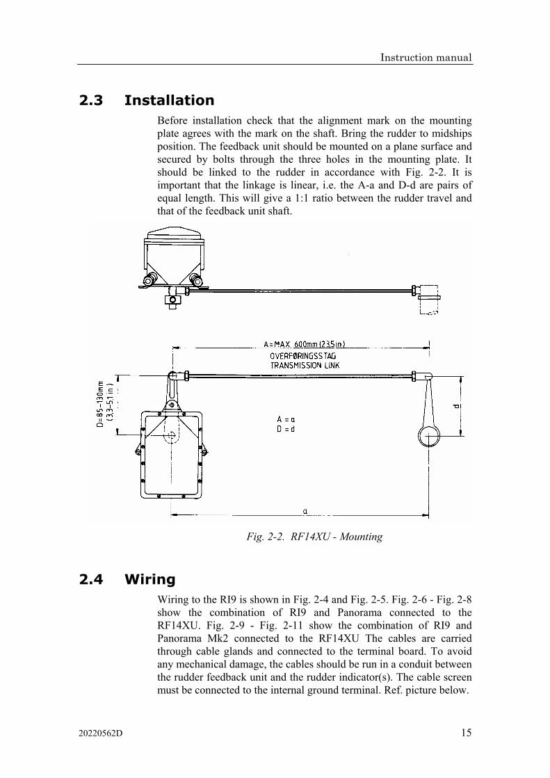
2.3 Installation Before installation check that the alignment mark on the mounting plate agrees with the mark on the shaft. Bring the rudder to midships position. The feedback unit should be mounted on a plane surface and secured by bolts through the three holes in the mounting plate. It should be linked to the rudder in accordance with Fig. 2-2. It is important that the linkage is linear, i.e. the A-a and D-d are pairs of equal length. This will give a 1:1 ratio between the rudder travel and that of the feedback unit shaft.
Fig. 2-2. RF14XU - Mounting
2.4 Wiring Wiring to the RI9 is shown in Fig. 2-4 and Fig. 2-5. Fig. 2-6 - Fig. 2-8 show the combination of RI9 and Panorama connected to the RF14XU. Fig. 2-9 - Fig. 2-11 show the combination of RI9 and Panorama Mk2 connected to the RF14XU The cables are carried through cable glands and connected to the terminal board. To avoid any mechanical damage, the cables should be run in a conduit between the rudder feedback unit and the rudder indicator(s). The cable screen must be connected to the internal ground terminal. Ref. picture below.

Simrad RI9 Rudder Angle Indicator
16 20220562D
Fig. 2-3 Screen termination
The feedback unit has an external ground terminal and must have a proper ground connection to the hull. The grounding wire should be as short as possible and at least 10 mm wide.
Note ! If the RF14XU and the indicators are powered from an unsmoothed 24V supply, the enclosed 470µF capacitor must be connected across the supply voltage terminals (+, –) to avoid off-set on the indicator reading.
Fig. 2-4. RI9-RF14XU Wiring diagram

Instruction manual
20220562D 17
Fig. 2-5. RI9-RF14XI Wiring diagram
VOLTAGE FB
SUPPLY +
2x1,
5 sq
.mm
3x1,
5 sq
.mm
RF1
4XU
RU
DD
ER
FE
ED
BA
CK
UN
IT
TOTA
L N
UM
BE
R O
F IN
DIC
ATO
RS
: 4
RU
DD
ER
AN
GLE
IND
ICAT
OR
S
RI9
RI9
RI9
PA
NO
RAM
A
12
34
56
8910U
3
1
2
SUPPLY -
VOLTAGE FB
SUPPLY +SUPPLY -
VOLTAGE FB
SUPPLY +SUPPLY -
24V
DC
Fig. 2-6. Wiring diagram
RI9, Panorama and RF14XU on 24V DC Mains

Simrad RI9 Rudder Angle Indicator
18 20220562D
VOLTAGE FB
SUPPLY +
3x1,
5 sq
.mm
3x1,
5 sq
.mm
TOTA
L N
UM
BE
R O
F IN
DIC
ATO
RS
: 8
RU
DD
ER
AN
GLE
IND
ICAT
OR
S
RI9
RI9
RI9
PA
NO
RAM
A
12
34
56
2x1,
5 sq
.mm
MAI
NS
110-
220V
50-
60H
z
RI4
RE
CTI
FIER
BO
X
STA
ND
AR
DR
UD
DE
R P
OT.
ME
TER
12
3
110V
220V
12
34
56
3
1
2
SEPA
RAT
E LA
MP
SU
PPL
Y
SUPPLY -
VOLTAGE FB
SUPPLY +SUPPLY -
VOLTAGE FB
SUPPLY +SUPPLY -
Fig. 2-7. Wiring diagram Panorama and RI9 on AC Mains using a Robertson RI4 Rectifier and
“standard rudder potentiometer”

Instruction manual
20220562D 19
VOLTAGE FB
SUPPLY +
3x1,
5 sq
.mm
3x1,
5 sq
.mm
RF1
4XU
RU
DD
ER
FE
ED
BA
CK
UN
IT
TOTA
L N
UM
BE
R O
F IN
DIC
ATO
RS
: 8
RU
DD
ER
AN
GLE
IND
ICAT
OR
S
RI9
RI9
RI9
PA
NO
RAM
A
FOR
RI4
AN
D O
THE
R U
NS
MO
OTH
ED
24V
SU
PP
LY C
ON
NE
CT
THE
E
NC
LOS
ED
CA
PA
CIT
OR
AS
SH
OW
N
NO
TE:
12
34
56
8910U
3
1
2
SEPA
RAT
E LA
MP
SU
PPL
Y
SUPPLY -
VOLTAGE FB
SUPPLY +SUPPLY -
VOLTAGE FB
SUPPLY +SUPPLY -
(NO
T S
IMR
AD
SU
PPLY
)
+
2x1,
5 sq
.mm
110/
220V
AC
24V
DC
RE
GU
LATE
D P
OW
ER
SU
PPL
Y
Fig. 2-8 Wiring diagram Panorama and RI9 on AC Mains with regulated power supply

Simrad RI9 Rudder Angle Indicator
20 20220562D
VOLTAGE FB
SUPPLY +
2x1,
5 sq
.mm
3x1,
5 sq
.mm
RF1
4XU
RU
DD
ER
FE
ED
BA
CK
UN
IT
TOTA
L N
UM
BE
R O
F IN
DIC
ATO
RS
: 8
RU
DD
ER
AN
GLE
IND
ICAT
OR
S
RI9
RI9
RI9
PAN
OR
AM
A M
k2
31
25
4
8910U
SUPPLY -
VOLTAGE FB
SUPPLY +SUPPLY -
VOLTAGE FB
SUPPLY +SUPPLY -
24V
DC
U
Fig. 2-9 Wiring diagram RI9, Panorama Mk2 and RF14XU on 24V DC Mains

Instruction manual
20220562D 21
VOLTAGE FB
SUPPLY +
2x1,
5 sq
.mm
3x1,
5 sq
.mm
TOTA
L N
UM
BE
R O
F IN
DIC
ATO
RS
: 4
RU
DD
ER
AN
GLE
IND
ICAT
OR
S
RI9
RI9
RI9
PAN
OR
AM
A M
k2
31
25
4
2x1,
5 sq
.mm
MAI
NS
110-
220V
50-
60H
z
RI4
RE
CTI
FIE
R B
OX
STA
ND
AR
DR
UD
DE
R P
OT.
ME
TER
12
3
110V
220V
12
34
56
SUPPLY -
VOLTAGE FB
SUPPLY +SUPPLY -
VOLTAGE FB
SUPPLY +SUPPLY -
U
Fig. 2-10 Wiring diagram Panorama Mk2 and RI9 on AC Mains using a Robertson RI4 Rectifier
and “Standard Rudder Potentiometer”

Simrad RI9 Rudder Angle Indicator
22 20220562D
VOLTAGE FB
SUPPLY +
3x1,
5 sq
.mm
RF1
4XU
RU
DD
ER
FE
ED
BA
CK
UN
IT
TOTA
L N
UM
BE
R O
F IN
DIC
ATO
RS
: 4
RU
DD
ER
AN
GLE
IND
ICAT
OR
S
RI9
RI9
RI9
PAN
OR
AM
A M
k2
FOR
RI4
AN
D O
THE
R U
NS
MO
OTH
ED
24V
SU
PP
LY C
ON
NE
CT
THE
E
NC
LOS
ED
CA
PA
CIT
OR
AS
SH
OW
N
NO
TE:
31
25
4
8910U
SUPPLY -
VOLTAGE FB
SUPPLY +SUPPLY -
VOLTAGE FB
SUPPLY +SUPPLY -
U
2x1,
5 sq
.mm
Sup
ply
+
(NO
T S
IMR
AD
SU
PPLY
)
+
Sup
ply
-
2x1,
5 sq
.mm
110/
220V
AC
24V
DC
RE
GU
LATE
D P
OW
ER
SU
PPL
Y
Fig. 2-11 Wiring diagram Panorama Mk2 and RI9 on AC Mains with regulated power supply
110/220VAC – 24VDC 2A

Instruction manual
20220562D 23
2.5 Other rudder angles The RF14XU is normally delivered for ±45 degrees rudder angle (violet, brown and pink leads are not connected). For ±60 degrees, connect brown lead to terminal 10. For ±70 degrees, connect pink to terminal 10 and for ±90 degrees, connect the violet lead to terminal 10. White lead must remain connected. To reverse the indicator deflection, the brown lead to terminal 8 must be connected to terminal 9. All is referred to connections between the terminal board and the internal of RF14XU, see Fig. 2-12
VIOLET
BROWN
PINK
BLAC
K
REDWH
ITE
WH
ITE
BLAC
K
RED
BLUE (GND)
YELLOW (+5V)
GREEN (WIPER)
NOTE 1
NOTE 2
9 8 10 7 6 5
RF14XU ELECTRONIC MODULE(VIEWED FROM BACK SIDE)
NOTE 1: Brown lead normally connected to . Move to to invert the rudder indicator deflection.
NOTE 2: Normally connected for +/-45° rudder angle (violet, brown and pink leads are not connected). For +/-60° connect brown lead to terminal 10, for +/-70° connect pink lead to terminal 10, for +/-90° connect violet lead to terminal 10. White lead must remain connected.
BRO
WN
8 9
89
TOPOT.METER
Fig. 2-12. RF14XU, Internal wiring
Note ! Inside the Feedback Unit cover, a piece of moisture protecting sponge is attached. The sponge produces a corrosion preventive gas, and to increase the long-range efficiency of the gas, avoid keeping the unit open over long time periods.

Simrad RI9 Rudder Angle Indicator
24 20220562D
2.6 Adjustments After having tightened all mechanical parts and connected all cables, the following adjustment must be carried out:
1. Check that the rudder is set to midship position.
2. Measure the voltage between "U" and "+", respectively "-" on the RF14XU terminal board. If the two measured voltages do not have the same numerical value, loosen the two clamping screws on the potentiometer and turn the potentiometer housing. (Fig. 2-13 pos. 5) until the same numerical value is measured. The RF14XU is now set to midposition. Tighten the two clamping screws.
After installation, the cable glands should be sealed with silicon to prevent water from seeping in. Also apply silicon grease to the gasket between the bottom and top cover.
2.7 Spare parts Part no. Pos. Description
22504005 Transmission Link 44132306 Ball joint 22500300 Shaft coupling 22500458 1 Gasket 22501605 2 Electronic XU drive module 44105120 3 Actuator 44105146 4 Limit switch 44118388 5 Potentiometer 5Kohm 44132033 6 Corrosion inhibitor sponge 22500284 7 Activator block 22500276 8 Activator disc
Fig. 2-13 RF14XU - Spare Parts

Instruction manual
20220562D 25
3 RF45X RUDDER FEEDBACK UNIT
3.1 General
The RF45X is a medium duty rudder feedback unit. Mechanically it is identical to it’s predecessor RF45, therefore it is a repairable rather than a potted throw away item. Electrically it outputs a frequency (pulse width modulated) signal that matches with the J3XX input (AP35/AP50), but it can also output a frequency signal (selectable via internal jumpers) that matches with AP45 and AP9 Mk3. The RF45X can also operate on 24V DC, a useful feature when connected in a stand alone rudder angle indicator system.
The unit is mounted close to the rudder stock and is mechanically connected to the rudder by the RF45 transmission link.
3.2 Technical specifications Dimensions: .............................................................................. See Fig. 3-1 and Fig. 3-2.
Weight: ...................................................................................................... 1,0 kg (2,2 lbs.)
Material: ................................................................................................Polyacetal (POM)
Supply voltage: ................................................ 12-24 VDC –10%/+30%, system supplied
Environmental Protection:........................................................................................... IP56
Temperature range:
Operation: .......................................................... –25 to +55°C (–13 to +130°F)
Storage: ............................................................. –30 to +80°C (–22 to + 176°F)
Cable:.................................................................................................................. 2 m (6 ft.)
Rudder angle:..............................................................................................................± 45°
Output signal: ........................................................ Polarity-independent frequency signal
Frequency resolution:....................... Center: 3400 Hz, 20 Hz/degree of change
Linearity:...................................................................... ± 3° up to 45° of rudder
Current output for rudder angle indicator (only for stand-alone system).. 0.1mA - 1.1mA
Number of indicators (only for stand-alone system):......................................... 5 in series

Simrad RI9 Rudder Angle Indicator
26 20220562D
Fig. 3-1 RF45X – Dimensions
Fig. 3-2 RF45/Standard Transmission Link - dimensions
3.3 Mounting The RF45X is normally mounted with the shaft pointing upwards. It can, however, also be mounted with the shaft pointing downwards if that appears to be more convenient. The deflection can then be inverted as illustrated in Fig. 3-4.
An “upside-down” installation will make access to within the unit more convenient as the unit can be opened without moving it from the mounting base. To open the unit, unscrew the two screws at the bottom and remove the cover. Be careful with the wires when you put back the cover.
Instruction manual
20220562D 27
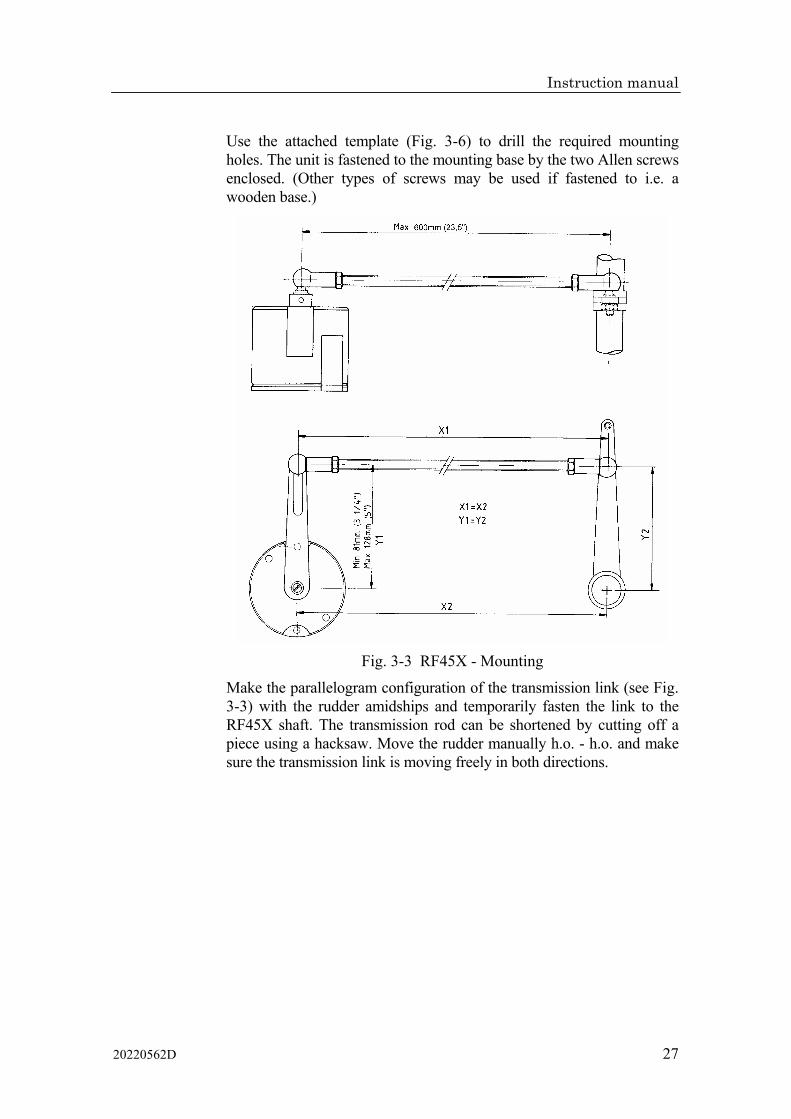
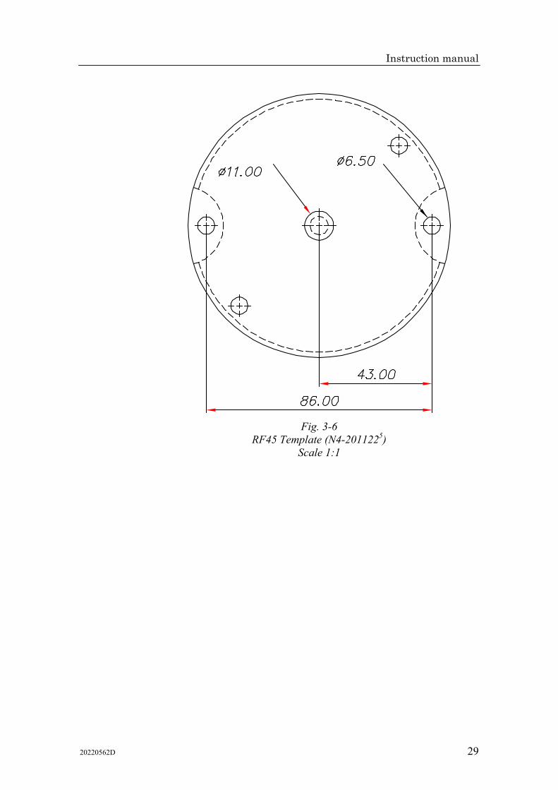
Use the attached template (Fig. 3-6) to drill the required mounting holes. The unit is fastened to the mounting base by the two Allen screws enclosed. (Other types of screws may be used if fastened to i.e. a wooden base.)
Fig. 3-3 RF45X - Mounting
Make the parallelogram configuration of the transmission link (see Fig. 3-3) with the rudder amidships and temporarily fasten the link to the RF45X shaft. The transmission rod can be shortened by cutting off a piece using a hacksaw. Move the rudder manually h.o. - h.o. and make sure the transmission link is moving freely in both directions.

Simrad RI9 Rudder Angle Indicator
28 20220562D
3.4 Electrical connection
Fig. 3-4 RF45X Internal Wiring
Fig. 3-5. RI9-RF45X Wiring diagram
Note ! For RF45X the supply voltage can be 12/24VDC.
Instruction manual
20220562D 29
Fig. 3-6
RF45 Template (N4-2011225) Scale 1:1

Simrad RI9 Rudder Angle Indicator
30 20220562D
Instruction manual
20220562D 31
3.5 Spare parts
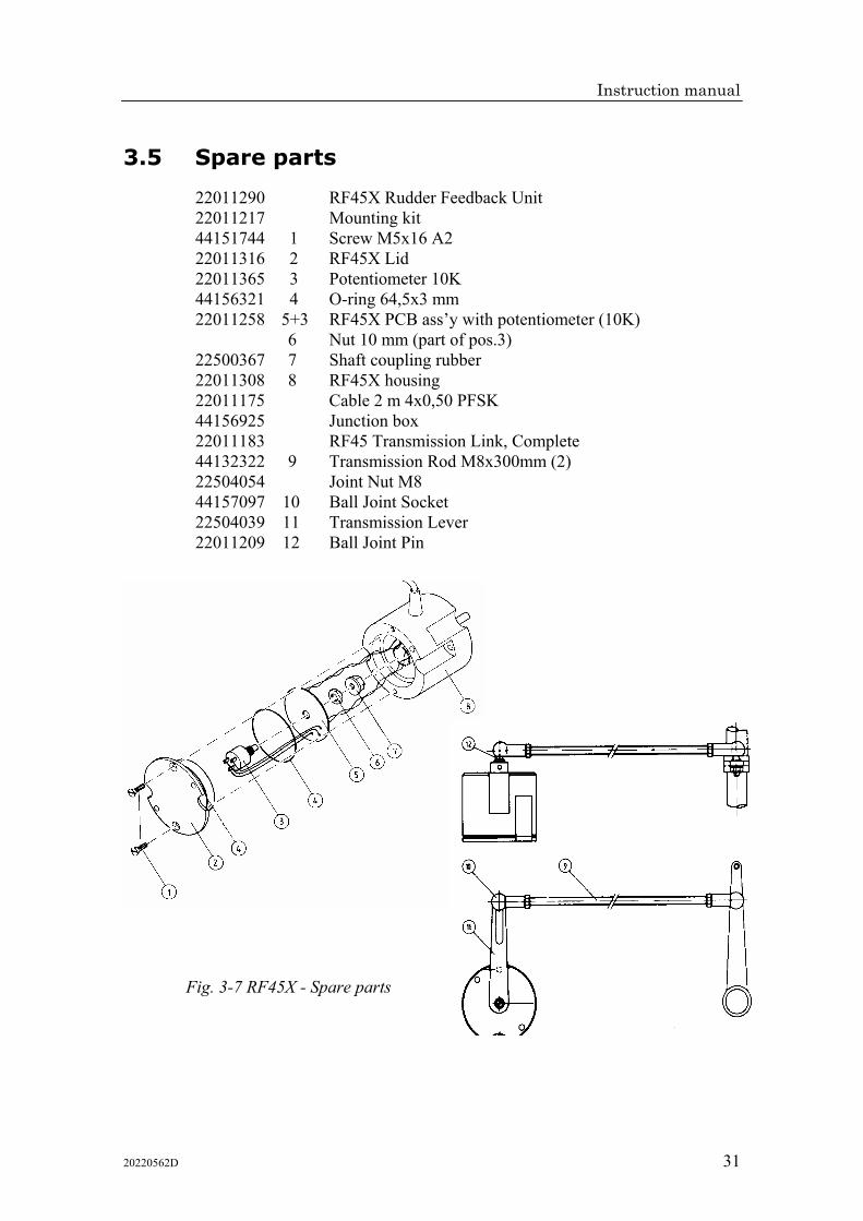
22011290 RF45X Rudder Feedback Unit 22011217 Mounting kit 44151744 1 Screw M5x16 A2 22011316 2 RF45X Lid 22011365 3 Potentiometer 10K 44156321 4 O-ring 64,5x3 mm 22011258 5+3 RF45X PCB ass’y with potentiometer (10K)
6 Nut 10 mm (part of pos.3) 22500367 7 Shaft coupling rubber 22011308 8 RF45X housing 22011175 Cable 2 m 4x0,50 PFSK 44156925 Junction box 22011183 RF45 Transmission Link, Complete 44132322 9 Transmission Rod M8x300mm (2) 22504054 Joint Nut M8 44157097 10 Ball Joint Socket 22504039 11 Transmission Lever 22011209 12 Ball Joint Pin
Fig. 3-7 RF45X - Spare parts

Simrad RI9 Rudder Angle Indicator
32 20220562D