Simplifying Board Bringup
40
Freescale Semiconductor Application Note © Freescale Semiconductor, Inc., 2007. All rights reserved. To help expedite Power Architecture™ board bringup, this application note describes how to port the CodeWarrior™ target initialization file from the Freescale MPC8555CDS development system to a custom development system. The target initialization file offers many benefits, such as the ability to debug a system before there is working code and a working system. The CodeWarrior integrated development environment (IDE) can manually read/write the processor’s internal registers or it can automatically initialize Power Architecture processors through the target initialization file. The target initialization file is a command file with contents that can be similar to boot code because it can contain the configuration of the Power Architecture interfaces and registers as well as code to set up interrupt service routines in the double data rate (DDR) memory controller. The target initialization file is included in the Freescale board support package (BSP) for each Power Architecture development system. Also, the target initialization files for most Freescale development systems are included in the following Freescale CodeWarrior IDE installation directories: • CWInstall\Power Architecture_EABI_Support\Initialization_Files \BDM\ • CWInstall\Power Architecture_EABI_Support\Initialization_Files \JTAG\ Contents 1 Initialization File Use Cases . . . . . . . . . . . . . . . . . . . . . 2 2 Enable the Target Initialization File . . . . . . . . . . . . . . 3 2.1 CodeWarrior EPPC Target Settings Panel . . . . . . . 3 2.2 CodeWarrior Flash Programmer Settings Panel . . .5 3 Syntax and Command Set . . . . . . . . . . . . . . . . . . . . . . . 5 4 Flow of Target Initialization File . . . . . . . . . . . . . . . . . 7 5 8555CDS_init_linux.cfg Target Initialization File . . . . 8 5.1 Header . . . . . . . . . . . . . . . . . . . . . . . . . . . . . . . . . . . 9 5.2 Delay Loop . . . . . . . . . . . . . . . . . . . . . . . . . . . . . . . 9 5.3 Invalidate BR0 . . . . . . . . . . . . . . . . . . . . . . . . . . . 10 5.4 Disable L2 ECC . . . . . . . . . . . . . . . . . . . . . . . . . . 10 5.5 Configure Internal SRAM for the Default . . . . . . 10 5.6 Activate Debug Interrupt and Enable SPU . . . . . . 11 5.7 Invalidate and Disable L1 Instruction and Data Cache . . . . . . . . . . . . . . . . . . . . . . . . . . . . . . 12 5.8 Set Up Memory Map (MMU TLBs) . . . . . . . . . . . 13 5.9 Move CCSRBAR . . . . . . . . . . . . . . . . . . . . . . . . . 18 5.10 Configure the Boot Page Translation Register . 18 5.11 Workaround for DLL Stabilization . . . . . . . . . . . 19 5.12 Workaround for Local Bus DLL . . . . . . . . . . . . 19 5.13 Disable Internal SRAM . . . . . . . . . . . . . . . . . . . 20 5.14 Local Access Window Configuration . . . . . . . . 20 5.15 DDR Initialization . . . . . . . . . . . . . . . . . . . . . . . . 24 5.16 Local Bus Memory Controller Configuration . .25 5.17 Set up Interrupt Handlers in DDR . . . . . . . . . . . 33 5.18 Activate Debug Interrupt and Enable SPU . . . . . 35 5.19 Set Up L1 Cache . . . . . . . . . . . . . . . . . . . . . . . . 35 5.20 Time Base Enable . . . . . . . . . . . . . . . . . . . . . . . . 36 5.21 UART Configuration . . . . . . . . . . . . . . . . . . . . . 36 5.22 CodeWarrior Debugger Configuration . . . . . . . . 36 6 Conclusion . . . . . . . . . . . . . . . . . . . . . . . . . . . . . . . . . 37 7 Revision History . . . . . . . . . . . . . . . . . . . . . . . . . . . . . 37 Simplifying Board Bringup Porting a CodeWarrior™ Initialization File to Your System by Karl Gundal Field Application Engineer Freescale Semiconductor, Inc. Austin, TX Document Number: AN3366 Rev.1, 05/2007
Transcript of Simplifying Board Bringup

Freescale SemiconductorApplication Note
© Freescale Semiconductor, Inc., 2007. All rights reserved.
To help expedite Power Architecture™ board bringup, this application note describes how to port the CodeWarrior™ target initialization file from the Freescale MPC8555CDS development system to a custom development system. The target initialization file offers many benefits, such as the ability to debug a system before there is working code and a working system.
The CodeWarrior integrated development environment (IDE) can manually read/write the processor’s internal registers or it can automatically initialize Power Architecture processors through the target initialization file. The target initialization file is a command file with contents that can be similar to boot code because it can contain the configuration of the Power Architecture interfaces and registers as well as code to set up interrupt service routines in the double data rate (DDR) memory controller. The target initialization file is included in the Freescale board support package (BSP) for each Power Architecture development system. Also, the target initialization files for most Freescale development systems are included in the following Freescale CodeWarrior IDE installation directories:
• CWInstall\Power
Architecture_EABI_Support\Initialization_Files
\BDM\
• CWInstall\Power
Architecture_EABI_Support\Initialization_Files
\JTAG\
Contents1 Initialization File Use Cases . . . . . . . . . . . . . . . . . . . . .22 Enable the Target Initialization File . . . . . . . . . . . . . . 3
2.1 CodeWarrior EPPC Target Settings Panel . . . . . . .32.2 CodeWarrior Flash Programmer Settings Panel . . .5
3 Syntax and Command Set . . . . . . . . . . . . . . . . . . . . . . .54 Flow of Target Initialization File . . . . . . . . . . . . . . . . .75 8555CDS_init_linux.cfg Target Initialization File . . . .8
5.1 Header . . . . . . . . . . . . . . . . . . . . . . . . . . . . . . . . . . .95.2 Delay Loop . . . . . . . . . . . . . . . . . . . . . . . . . . . . . . .95.3 Invalidate BR0 . . . . . . . . . . . . . . . . . . . . . . . . . . .105.4 Disable L2 ECC . . . . . . . . . . . . . . . . . . . . . . . . . .105.5 Configure Internal SRAM for the Default . . . . . .105.6 Activate Debug Interrupt and Enable SPU . . . . . .115.7 Invalidate and Disable L1 Instruction and Data Cache . . . . . . . . . . . . . . . . . . . . . . . . . . . . . .125.8 Set Up Memory Map (MMU TLBs) . . . . . . . . . . .135.9 Move CCSRBAR . . . . . . . . . . . . . . . . . . . . . . . . .185.10 Configure the Boot Page Translation Register . 185.11 Workaround for DLL Stabilization . . . . . . . . . . .195.12 Workaround for Local Bus DLL . . . . . . . . . . . . 195.13 Disable Internal SRAM . . . . . . . . . . . . . . . . . . .205.14 Local Access Window Configuration . . . . . . . . 205.15 DDR Initialization . . . . . . . . . . . . . . . . . . . . . . . .245.16 Local Bus Memory Controller Configuration . .255.17 Set up Interrupt Handlers in DDR . . . . . . . . . . .335.18 Activate Debug Interrupt and Enable SPU . . . . .355.19 Set Up L1 Cache . . . . . . . . . . . . . . . . . . . . . . . . 355.20 Time Base Enable . . . . . . . . . . . . . . . . . . . . . . . .365.21 UART Configuration . . . . . . . . . . . . . . . . . . . . .365.22 CodeWarrior Debugger Configuration . . . . . . . .36
6 Conclusion . . . . . . . . . . . . . . . . . . . . . . . . . . . . . . . . .377 Revision History . . . . . . . . . . . . . . . . . . . . . . . . . . . . .37
Simplifying Board BringupPorting a CodeWarrior™ Initialization File to Your System
by Karl GundalField Application EngineerFreescale Semiconductor, Inc.Austin, TX
Document Number: AN3366Rev.1, 05/2007

Simplifying Board Bringup, Rev.1
2 Freescale Semiconductor
Initialization File Use Cases
This application note provides the following information:
• How to enable the CodeWarrior target initialization file.
• Syntax and command sets and overall flow of the target initialization file.
• How to analyze each section of the target initialization file and identify the sections to port.
Most information in this application note can be used across all Power Architecture products, but there may be small differences due to product implementations. For example, the PowerQUICC™ II Pro memory management unit (MMU) differs from the PowerQUICC III MMU.
After reading this application note, you should be able to modify the CodeWarrior target initialization file to configure the following modules:
• L1 Instruction and Data cache
• L2 cache/SRAM
• Memory map through local access windows (LAWs)
• Memory management unit (MMU: TLBs)
• Flash memory devices connected to the local bus
• DDR memory controller
• Exception handlers in DDR
1 Initialization File Use CasesWhether you need to use a target initialization file depends on your purpose. Use the file during board bringup to configure the Power Architecture processor (in this case, the MPC8555). Before you can test or debug basic functionality or program flash memory, you may need to initialize the local bus, SDRAM/DDR, L1/L2 cache, memory map (local access windows and ATMUs), memory management (MMU through TLBs), interrupts, or other functionality. Following are four cases in which use of a target initialization file accelerates the board bringup process:
• From the target initialization file, use register settings and code that pertain to your design rather than start from scratch. Start by comparing the block diagrams of your design to that of the Freescale development system to determine what is similar. Then focus on those sections. After verifying that sections of the target initialization file can work in your design, copy the register settings and code into your boot code.
• You need to use the CodeWarrior debugger to program flash memory for a new prototype. In this case, the CodeWarrior debugger needs to download its flash algorithm to temporary memory on the target system. Usually, external DDR memory is the choice, although other memory can be used instead, such as MPC8555 internal L2/SRAM. You must ensure that the Power Architecture processor is properly programmed so the selected memory space can be used. If the processor has available internal RAM, it may be preferable to use this RAM for flashing because the DDR memory may not yet be verified to work.
• For a new prototype in which flash memory is not working, use the target initialization file to configure external/internal memory, download your code to memory, and run the code from there.
• In some Power Architecture devices, if the power-on reset (POR) configuration options are incorrect, you can use the target initialization file to reconfigure these settings automatically.

Simplifying Board Bringup, Rev.1
Freescale Semiconductor 3
Enable the Target Initialization File
The following cases do not require use of a target initialization file:
• Board bringup is complete and boot code is successfully running on the development system.
• Boot code is up and running and registers can be modified in the boot code or through the boot loader. However, it may be easier to make temporary changes through the target initialization file.
2 Enable the Target Initialization FileTwo CodeWarrior settings panels control target initialization files:
• EPPC target settings panel. The setting takes effect only when you connect through one of the following CodeWarrior menu options:
— Project → RUN
— Project → RESTART
— Debug → CONNECT
— Debug → RESTART
— Project → DEBUG
• CodeWarrior flash programmer settings panel. The setting takes effect only when you program flash memory.
2.1 CodeWarrior EPPC Target Settings PanelFigure 1 shows the options available through the target settings panel. From the CodeWarrior debugger tool, select DEBUG VERSION SETTINGS from the Edit menu and then scroll down on the left side of the Debug Version Settings panel and expand DEBUGGER. Then select the EPPC debugger settings
Figure 1. CodeWarrior EPPC Target Settings Panel

Simplifying Board Bringup, Rev.1
4 Freescale Semiconductor
Enable the Target Initialization File
Checking the USE TARGET INITILIZATION FILE checkbox activates the next line, where you can enter the name of a target initialization file. Optionally, you can click the BROWSE button to select a target initialization file from a dialog box. In either case, the contents of the specified file are processed and sent to the target development system.
If you use the ATTACH function, the CodeWarrior debugger assumes that code is already running on the board and that the Power Architecture processor is already configured. Therefore the CodeWarrior debugger does not run the target initialization file even if it is enabled.
If you enable the CodeWarrior debugger to use the target initialization file, you must enable the RESET TARGET ON LAUNCH setting in the USB TAP Settings panel, as shown in Figure 2. This sends a hard reset to the processor to prepare it to receive the commands. Note that HRESET is not asserted for Debug → ATTACH TO PROCESS, regardless of this setting.
Figure 2. CodeWarrior USB TAP Settings Panel

Simplifying Board Bringup, Rev.1
Freescale Semiconductor 5
Syntax and Command Set
2.2 CodeWarrior Flash Programmer Settings PanelTo access the flash programmer settings panel, shown in Figure 3, select FLASH PROGRAMMER from the Tools menu. This panel is used only to program flash memory, so the USE TARGET INITIALIZATION option in this panel takes effect only when you program flash memory.
Figure 3. CodeWarrior Flash Programmer Settings Panel
3 Syntax and Command SetThe target initialization file is a command file that contains proprietary information used to program the Power Architecture registers. The command syntax follows these rules:
• White spaces and tabs are ignored.
• Character case is ignored.
• Unless otherwise noted, values can be specified in hexadecimal, octal, or decimal:
— Hexadecimal values are preceded by 0x (for example, 0xDEADBEEF).
— Octal values are preceded by 0 (for example, 01234567).
— Decimal values start with a non-zero numeric character (for example, 1234).
• Comments start with a semicolon (;) or pound sign (#) and continue to the end of the line.

Simplifying Board Bringup, Rev.1
6 Freescale Semiconductor
Syntax and Command Set
The commands listed in Table 1 are used in the example target initialization file discussed in this application note. This is not an exhaustive list. Other commands can be used in other initializations files. For a complete list of commands, see Appendix A of the CodeWarrior reference file “Targeting Embedded Power Architecture” in the {CodeWarrior}\Help\PDF folder.
Table 1. Initialization File Commands Used in Our Example
Command Description Syntax Argument/Parameters Example
Reset Resets the target processor and either run/stop debugger.
Reset code Code: 0: Reset the processor then
debugger runs1: Reset the processor then
debugger stops
N/A
Run Starts program execution at the current program counter (PC) address.
Run N/A N/A
Sleep Causes the debugger to wait the specified number of milliseconds before continuing to the next command.
sleep milliseconds Milliseconds: The number of milliseconds (in decimal) to pause the processor
To pause execution for 10 milliseconds:
sleep 10
Stop Stops program execution and halts the target processor.
Stop N/A N/A
Writereg Writes the specified data to a register.
writereg regName value
• regName: the name of the register
• value: the value (in hexadecimal, octal, or decimal) to write to the register
To write the value 0x00001002 to the MSR register: writereg MSR 0x00001002
Writespr Writes the specified value to the specified SPR register.
writespr regNumber value
• regNumber: the SPR register number (in hexadecimal, octal, or decimal)
• value: the value (in hexadecimal, octal, or decimal) to write to the register
To write the value 0x0220000 to SPR register 638:writespr 638 0x02200000
Writemem.l Writes a long integer (32 bytes) of data to the specified memory location.
writemem.l address value
• Address: the memory address to modify (in hexadecimal, octal, or decimal)
• value: the 32-bit value (in hexadecimal, octal, or decimal) to write to the memory address
To write the long integer value 0x12345678 to memory location 0x0001FF00:
writemem.w 0x0001FF00 0x12345678

Simplifying Board Bringup, Rev.1
Freescale Semiconductor 7
Flow of Target Initialization File
4 Flow of Target Initialization FileThe flow of the initialization file for our MPC8555 CDS example is as follows (sections in Bold indicate sections of code that may need to be ported or changed):
• Invalidate BR0.
• Disable L2 ECC.
• Configure L2/internal SRAM as internal SRAM and cover the default 4 Kbyte MMU page: 0xFFFFF000–0xFFFFFFFF. Now we can write code to internal SRAM and then execute the code.
— Disable L2/internal SRAM.
— Set L2 Block 0 Base to 0xFFFE0000 for 128 Kbyte. The internal SRAM range is 0xFFFE0000–0xFFFFFFFF.
— Enable internal SRAM.
• Activate debug interrupt and enable the spurious vector register (SPU).
• Work around PQ3.
— Set interrupt vectors.
— At the reset address, write a branch to 0xFFFFF000.
• Invalidate and disable the L1 instruction and data cache.
• Set up the memory management unit (MMU) for the memory map.— Define the memory map and attributes and then program the TLBs though the MAS
registers.— Comment out all other TLB configurations.
• Set CCSRBAR to the base you need. — CCSRBAR is the base to MPC8555 internal registers. CCSRBAR is changed from the
default value of 0xFF700000 to 0xE0000000. You can change this to another value if needed.
• Configure the boot page translation register (BPTR) and remove the 4 Kbyte boot page from the 0xFFFFF000 address.
— Again invalidate BR0 to prevent flash data damage.
— The boot sequencer re-enables CS0 access.
• Workaround for DLL stabilization (DDR DLL controller register)— The MPC8555 DDR DLL mode is not supported, so this section is not needed and should
be commented out. • Workaround for local bus DLL lock. This is needed only if the local bus DLL mode is used.• Disable internal SRAM. At this point we do not need to use the internal SRAM to run code, so
L2/internal SRAM is disabled.
• Configure local access windows (LAWs):— Define LAWs for all DDR, PCI1, PCI2, and local bus memory space. Reference the
memory map and program a unique LAWBARn and LAWARn for each memory range (that is, flash memory and so on).
— Comment out all other LAWBARn and LAWARn configurations.

Simplifying Board Bringup, Rev.1
8 Freescale Semiconductor
8555CDS_init_linux.cfg Target Initialization File
• DDR Initilization. To ensure that the DDR registers are changed correctly, read the following application notes:— AN2583, Programming the PowerQUICC™ III/PowerQUICC II Pro DDR SDRAM
Controller.— AN2582, Hardware and Layout Design Considerations for DDR Memory Interfaces.
• Configure the local bus memory controller:— Ensure that flash memory is connected to chip select 0 (CS0) and program OR0 and BR0
to reflect the correct attributes: port size (8, 16, or 32 bits), base address, and so on.— Comment out all other ORn and BRn configurations.
• Interrupt vector initialization:— Interrupt handlers are put in upper DDR space 0x00000000. Change this value if DDR is
not in this memory space.— In case of an exception during debug/board bring up, write 0x48000000 (an infinite loop
opcode) to all 18 interrupt handler locations. • Activate debug interrupts and enable the spurious vector register (SPU).
• Time base enable.
• The serial configuration UART enable received data available interrupt.
• CodeWarrior debugger settings:
— Trap debug event enable.
— Set the PC at the reset address (for Debug → CONNECT).
— For debugging, start at program entry point when the stack is not initialized.
5 8555CDS_init_linux.cfg Target Initialization FileThe target initialization file for a particular evaluation system is contained within the BSP and included in the CodeWarrior installation. The example discussed here is based on the target initialization file and is also included in the BSP for the MPC8555CDS development system. The complete BSP can be downloaded from MPC8555 product page (under Software → BOARD SUPPORT PACKAGES) at the Freescale web site listed on the back cover of this document. The BSP is embedded within an *.ISO file, which is a CD image that must be written to a burnable CD. As of the date of this application note, the latest *.ISO for the MPC8555CDS evaluation board is MPC8555CDS. _20060124.iso.
This file is over 350 Mbytes and may take a while to download. After it downloads, double click on the file to open up your CD writer. After burning the CD, you can find the target initialization file 8555CDS_init_linux.cfg for this evaluation system in the help\CW_debug directory.
The 8555CDS_init_linux.cfg file listed in this section is the complete CodeWarrior target initialization file to configure the MPC8555 in the MPC8555 CDS development system. To help explain this file/code, additional comments/paragraphs have been added in this application note. However, the code has not been changed. To simplify the discussion, the file is split into sections. To port this file to a board, you may need to change the code highlighted in Bold. Take time to understand all comments in the code.

Simplifying Board Bringup, Rev.1
Freescale Semiconductor 9
8555CDS_init_linux.cfg Target Initialization File
NOTE
Most configuration settings in the target initialization file are for a board bringup environment. Therefore, we recommend that settings such as address translation, caching, and so on be disabled.
Much of the code accesses the MPC8555 internal registers. All internal memory-mapped configuration, control, and status registers in the MPC8555E are contained within a 1-Mbyte address region (window). CCSRBAR points to the base of this 1-Mbyte window. There is no address translation for CCSRBAR so there are no associated translation address registers. The window is always enabled with a fixed size of 1 Mbyte; no other attributes are attached, so there is no associated size/attribute register. This window takes precedence over all local access windows.
For flexibility, CCSRBAR is relocatable in the local address space. After power-on reset of the MPC8555, the default value for CCSRBAR is 0xFF70_0000. To access a register, just add the register offset to the address of CCSRBAR. For further information, consult the sections of the MPC8555 reference manual on the “Configuration, Control, and Status Base Address Register (CCSRBAR) and “Configuration, Control, and Status Register Map.”
5.1 HeaderThe header of the target initialization file is as follows.
########################################################################FILE# $RCSfile: 8555CDS_init_Linux.cfg,v $# $Date: 2006/01/20 10:20:00 $# $Modified: Haiying Wang# $Revision: 1.1 $#DESCRIPTION# initialization file for 8555 CDS board to debug kernel# This initialization file is according to the u-boot file# This file can only be used by CW for Linux 2.6 or above
#COPYRIGHT
# Copyright 2006 Freescale Semiconductor# All rights reserved.
#######################################################################
5.2 Delay LoopThe following three lines of code are commented out because this target initialization file does not expect the processor to be configured by code or the boot sequencer through the system board. Instead, this file is used to configure the processor. If the three lines of code were uncommented, the processor would be reset and the CodeWarrior debugger would be suspended for 100 ms, which would allow the processor to run on the board for 100 ms and start booting (as long as code is programmed on the board). At the end of the 100 ms, program execution would stop and the processor would halt. Then the board could configure itself. The 100 ms is an estimate of how long it may take to configure the board, and this value may need to be changed if you do not comment out these lines.
#reset 0 # reset & run#sleep 0x100#stop

Simplifying Board Bringup, Rev.1
10 Freescale Semiconductor
8555CDS_init_linux.cfg Target Initialization File
5.3 Invalidate BR0The lines of code shown here write 0x00001000 to the BR0 register (0xFF705000) because BR0 is at offset 0x0_5000 from CCSRBAR. This write disables chip-select 0 (CS0). Typically, CS0 is connected to the system flash memory. BR0 is the base register for CS0. 0x00001000 sets this port to a 16-bit interface using the GPCM and also invalidates this port because at this point in time we do not want the processor to boot from flash memory when it is reset. Later on in this file, BR0 is validated such that the processor boots from flash memory when it is reset.
# invalidate BR0writemem.l 0xFF705000 0x00001000
5.4 Disable L2 ECC0xFF720E44 points to the L2ERRDIS register. In this initialization file, the L2 cache is configured as SRAM so the TLBs can be initialized by running a small piece of code written into L2 SRAM and executed. Therefore, the error correcting code (ECC) needs to be disabled. After power-on reset, the contents of the internal SRAM data and ECC arrays are random and should be initialized before they are read. Also, if the processor or any other device that uses sub-cache-line transactions initializes the internal SRAM, ECC error checking should be disabled during initialization to avoid false ECC errors generated during the read-modify-write process used for sub-cache-line writes to the disable register (L2ERRDIS[MBECCDIS, SBECCDIS]). Note that if a DMA controller using cache-line writes initializes the array, ECC checking can remain enabled during the initialization process.
The following code disables the ECC.
# Workaround for ABIST offwritemem.l0xFF720E44 0x0000000C# L2ERRDIS[MBECCDIS]=1 L2ERRDIR[SBECCDIS]=1
5.5 Configure Internal SRAM for the DefaultPart of the target initialization file uses the MPC8555 internal SRAM to configure the MPC8555 by copying code to the internal SRAM and then executing the code. The code in this section configures the L2_Cache/internal SRAM as internal SRAM. After processor power-on reset (POR), only a default 4 Kbyte block of memory (0xFFFFF000–0xFFFFFFFF) is accessible until the MMU is set up with additional TLBs to access the rest of the memory space. Later on in this target initialization file, the additional TLBs are set up. However, at this point the internal SRAM is set up within this 4 Kbyte range of 0xFFFE0000–FFFFFFFF. Before L2CTL and L2SRBAR0 are configured, the L2 SRAM must be disabled. Then the properties are configured and finally the SRAM is enabled.
#################################################################################### configure internal SRAM to cover the default 4KB MMU page: 0xFFFFF000-0xFFFFFFFF##################################################################################### L2CTL# bit 0 = 0 - L2E: L2 SRAM disabled# bit 4-5 = 01 - L2BLKSZ: = 128KB# bit 13-15 = 001 - L2SRAM: Block 0 = SRAM 0writemem.l0xFF720000 0x64010000

Simplifying Board Bringup, Rev.1
Freescale Semiconductor 11
8555CDS_init_linux.cfg Target Initialization File
#The L2 cache/SRAM is disabled and invalidated. The size of internal L2_cache/SRAM equals 256 #Kbytes. The block size is set to 128 Kbytes and the L2_cache/SRAM is configured as two 128 #Kbyte blocks of SRAM. Block 0 is set to SRAM0 and Block1 is set to Unused.
# L2SRBAR0# bit 0-17 = BASE addr: 4GB-128KBwritemem.l0xFF720100 0xFFFE0000# This sets the base address of the L2 Block0 (SRAM0) to 0xFFFE0000. So the memory range is# 0xFFFE0000 – FFFFFFFF. # This equals = 1FFFF = 128 Kbytes and is appropriately aligned since the block size = 128 # Kbytes.# L2CTL# bit 0 = 1 - L2E: L2 SRAM enable# bit 4-5 = 01 - L2BLKSZ: = 128 Kbyte# bit 13-15 = 001 - L2SRAM: Block 0 = SRAM 0writemem.l0xFF720000 0xA4010000
#Now that the properties are configured, the L2 SRAM can be enabled. At this point the L2 SRAM#covers the default 4 Kbyte MMU page: 0xFFFFF000-0xFFFFFFFF.
####################################################################################
5.6 Activate Debug Interrupt and Enable SPUPowerQUICC III products such as the MPC8555 processor require the following work around so that the CodeWarrior debugger can obtain complete control of the processor. The code listed in this section performs the following tasks:
1. Activate debug interrupt MSR[DE] and MSR[SPE_APU] signal processing engine for floating-point operations.
2. IVPR (base addr) + IVOR15 (offset) is set to 0xFFFF_F000, which is in the 4 Kbyte memory space.
After power up, PowerQUICC III processors have a default of 4 Kbyte of memory enabled (0xFFFF_F000 to 0xFFFF_FFFF). Therefore, the debug interrupt vector should be in this range of addresses.
3. A hardware breakpoint (debug event) is programmed at 0xFFFF_F000 (debug interrupt address) into IAC1 and the memory is set up to enable this event. The processor is then reset to hit the breakpoint. Then the debug event is disabled and IAC1 is cleared.
A debug event can be enabled to occur by programming a specific address into the instruction address compare (IAC1) register and then enabling the event in the DBCR.
4. Set up the debug control register (DBCR) as follows:
— Bit[32] = 1 internal debug mode; (additionally MSR[DE] is configured for a a debug interrupt)
— Bit[39] = 1 TRAP
— Bit[40] = 1 IAC1 events can occur
#################################################################################### activate debug interrupt and enable SPU####################################################################################writeregMSR 0x02000200# set interrupt vectorswritereg IVPR 0xFFFF0000 # IVPR (compatible to the Flash)

Simplifying Board Bringup, Rev.1
12 Freescale Semiconductor
8555CDS_init_linux.cfg Target Initialization File
writereg IVOR15 0x0000F000 # debug - (a valid instruction should exist to be fetched)# write at the reset address a branch to 0xFFFFF000writemem.l 0xfffffffc 0x4BFFF004 # branch to 0xfffff000writereg IAC1 0xFFFFF000writereg DBCR0 0x41800000writemem.l 0xFFFFF000 0x60000000 # nop (or any valid opcode)runsleep 0x10stopwritereg DBCR0 0x41000000writereg IAC1 0x00000000# end of the workaround# This is a workaround for PQ3####################################################################################
5.7 Invalidate and Disable L1 Instruction and Data CacheThe internal SRAM is already configured, so now we can write code to internal SRAM and then execute code, as follows:
1. Write code to internal SRAM. Note the last instruction in the code is an infinite loop command.
2. Set the program counter to the memory location of the first instruction of the code.
3. Use the CodeWarrior sequence of run, sleep 0x10, stop to accomplish the following:
a) Allow the MPC8555 processor to start program execution at the current program counter (PC) address.
b) Cause the CodeWarrior debugger to wait 10 ms before continuing to the next command.
c) Stop program execution and halt the target processor.
This sequence allows the MPC8555 to run for 10 ms, which is enough time to run the code sequence in internal SRAM. The last line in the code should be an infinite loop. Therefore, the MPC8555 should finish executing the code and be running in an infinite loop by the time 10 ms passes. Then the CodeWarrior debugger reaches the stop command and halts the processor.
The following code, which invalidates and disables the L1 instruction and data cache, is copied to internal SRAM and then executed. In the first line, the opcode for mfspr r0,L1CSR0 is 0x7C12FAA6. A value of 0x7C12FAA6 is written to 0xFFFFF008 (which is part of the internal SRAM previously configured). The subsequent lines also copy the opcodes into memory. The PC is then programmed to 0xFFFFF008. Finally, the run, sleep, stop command allows the MPC8555 processor to run this code from internal memory.
#################################################################################### Invalidate cache###################################################################################writemem.l 0xFFFFF008 0x7C12FAA6 # mfspr r0,L1CSR0 /* invalidate d-cache */writemem.l 0xFFFFF00C 0x60000002# ori r0,r0,0x0002writemem.l 0xFFFFF010 0x7C0004AC # syncwritemem.l 0xFFFFF014 0x4C00012C # isyncwritemem.l 0xFFFFF018 0x7C12FBA6 # mtspr L1CSR0,r0writemem.l 0xFFFFF01C 0x4C00012C # isyncwritemem.l 0xFFFFF020 0x7C12FAA6 # mfspr r0,L1CSR0 /* disable d-cache */writemem.l 0xFFFFF024 0x3C20FFFF # lis rsp,-1writemem.l 0xFFFFF028 0x6021FFFE # ori rsp,rsp,0xfffewritemem.l 0xFFFFF02C 0x7C000838 # and r0,r0,rspwritemem.l 0xFFFFF030 0x7C0004AC # sync

Simplifying Board Bringup, Rev.1
Freescale Semiconductor 13
8555CDS_init_linux.cfg Target Initialization File
writemem.l 0xFFFFF034 0x4C00012C # isyncwritemem.l 0xFFFFF038 0x7C12FBA6 # mtspr L1CSR0,r0writemem.l 0xFFFFF03C 0x4C00012C # isyncwritemem.l 0xFFFFF040 0x7C13FAA6 # mfspr r0,L1CSR1 /* invalidate i-cache */writemem.l 0xFFFFF044 0x60000002 # ori r0,r0,0x0002writemem.l 0xFFFFF048 0x7C13FBA6 # mtspr L1CSR1,r0writemem.l 0xFFFFF04C 0x4C00012C # isyncwritemem.l 0xFFFFF050 0x7C13FAA6 # mfspr r0,L1CSR1 /* disable i-cache */writemem.l 0xFFFFF054 0x3C20FFFF # lis rsp,-1writemem.l 0xFFFFF058 0x6021FFFE # ori rsp,rsp,0xfffewritemem.l 0xFFFFF05C 0x7C000838 # and r0,r0,rspwritemem.l 0xFFFFF060 0x7C13FBA6 # mtspr L1CSR1,r0writemem.l 0xFFFFF064 0x4C00012C # isyncwritemem.l 0xFFFFF068 0x7C0004AC # syncwritemem.l 0xFFFFF06C 0x38800055 # li r4, 0x55 /*to confirm the running */writemem.l 0xFFFFF070 0x48000000 # /* infinite loop */writereg PC 0xfffff008runsleep 0x10stop####################################################################################
5.8 Set Up Memory Map (MMU TLBs)The MPC8555E has a flexible local memory map, which is the 32-bit address space visible to the processor as it accesses memory and I/O space. All memory accessed by the MPC8555E DDR SDRAM and local bus memory controllers exists in this memory map, as do all memory-mapped configuration, control, and status registers.
The MPC8555 has two programmable TLBs for memory management. After power-on reset, the MPC8555 provides only one default TLB entry to access boot code. This TLB entry allows accesses only within the highest 4 Kbytes of memory (0xFFFFF000–0xFFFFFFFF). Therefore, to access the full 8 Mbytes of default boot space, the 1 Mbyte of CCSR space, as well as any other address additional TLB entries, must be set up.
The MPC8555E on-chip memory array can be configured as a memory-mapped SRAM of 128 or 256 Kbytes. Configuration registers in the L2 cache controller set the base addresses and sizes for these windows. When enabled, these windows supersede all other mappings of these addresses for processor and global (snoopable) I/O transactions.
NOTE
SRAM windows must never overlap configuration space as defined by CCSRBAR. SRAM windows can overlap local access windows, but this is discouraged because processor and snoopable I/O transactions would map to the SRAM while non-snooped I/O transactions would be mapped by the local access windows. Only if all accesses to the SRAM address range are snoopable can results be consistent if the SRAM window overlaps a local access window. For information on configuring SRAM windows, see the section of the MPC8555 reference manual entitled, “L2 Memory-Mapped SRAM Base Address Registers 0–1 (L2SRBARn).”

Simplifying Board Bringup, Rev.1
14 Freescale Semiconductor
8555CDS_init_linux.cfg Target Initialization File
This section describes how to set up the MPC8555 memory management unit (MMU). You probably have a completely different memory map. However, to make it easier to port, you should write this memory map in the format shown in the first part of the code in this section. If any of these memory ranges are not used, then comment out those sections.
The two TLBs used for memory management are as follows:
• TLB1. A 16-entry fully associative array for variable-sized pages. Each entry can be configured from 4 Kbyte to 256 MByte.
• TLB0 . A 256-entry 2-way associative array with a fixed 4 Kbyte page.
In this example, we use 10 entries of TLB1 to define the memory map. To program the MMU (and therefore TLB1), write the correct configuration data to the MAS[0–4] registers and then issue a tlbwe command. The TLB Write Entry instruction (tlbwe) causes the information stored in certain locations of MAS[0–3] to be written to the TLB specified in MAS0. For a complete description of the MAS[0–4] registers, see the section on MMU assist registers in the MPC8555 reference manual. The MAS registers are implemented as 64-bit GPRs, the upper 32 bits of which are used only with 64-bit load, store, and merge instructions. The lower 32 bits need to be programmed. The remainder of this discussion pertains to the lower 32 bits. Therefore, the first bit (counting from left to right) is referenced as bit 32 and the last bit is referenced as bit 63.
For each unique memory range, the following must be changed:
• MAS0. To select a unique entry of the sixteen available entries, change the entry select number (ESEL), bits 44–47.
• MAS1. Change the translation size (TSIZE), bits 52–55, to the size of the page you need. If you need more than a 256 Mbyte page, concatenate several TLB entries.
• MAS2. Change the effective page number (EPN), bits 32–51, to the starting address of the page (or base address) you need. In most cases, you only need to change one other bit (I, bit 60) which determines if this is cacheable or cache inhibited space. It is good practice to set all memory space to cache inhibited because it is easier to debug a board when caches are not used. You can re-enable this space as needed.
• MAS3. In this example there is no address translation, so the real page number is the same as the effective page number. Also, all permission bits are enabled because this configuration is mainly for a board bringup and we are not concerned with user/supervisor space at this juncture. Change the real page number (RPN), bits 32–51, 1 to the same value as the effective page number.
• MAS4. Does not need to be changed.
For all other memory ranges that are not used in your system, the sub-sections should be commented out. In the code that follows, you may need to change the code highlighted in Bold to port this file to a board.
#################################################################################### Memory Map - LAW(Local Access Window configuration)###################################################################################
# 0xe00000000xe3ffffff TLB1_1CCSR 1M 0xe0000000 - 0xe00fffff# PCI1 IO 16M 0xe2000000 - 0xe2ffffff
# PCI2 IO 16M 0xe3000000 - 0xe3ffffff# 0x000000000x0fffffff TLB1_3DDR 256M# 0x100000000x1fffffff TLB1_4DDR 256M

Simplifying Board Bringup, Rev.1
Freescale Semiconductor 15
8555CDS_init_linux.cfg Target Initialization File
# 0xff0000000xffffffff TLB1_5FLASH 16M# 0x800000000x8fffffff TLB1_6PCI1 256M# 0x900000000x9fffffff TLB1_7PCI1 256M# 0xf80000000xf80fffff TLB1_8NVRAM/CADMUS1M# 0xf00000000xf3ffffff TLB1_9Local Bus SDRAM64M# 0xa00000000xafffffff TLB1_10PCI2 256M# 0xb00000000xbfffffff TLB1_11PCI2 256M
# MMU initialization
#
# MAS0: MMU read/write and replacement control # MAS1: descriptor context and configuration control# MAS2: EPN and page attributes# MAS3: RPN and access control# MAS4: Hardware replacement assist configuration
################################################################# define 64MB TLB1 entry 1: 0xe0000000 - 0xe3FFFFFF# for:# CCSR 0xe0000000 - 0xe00fffff# PCI1 IO 0xe2000000 - 0xe2ffffff# PCI2 IO 0xe3000000 - 0xe3ffffff
# Note that one TLB entry is used for CCSR and PCI1 and PCI2. This can be done since it is less than 256 Mbyte total space #and their attributes are the same.
writespr 624 0x10010000# MAS0 #selects 1st entry of TLB1writespr 625 0x80000800# MAS1 #validates tlb, sets to 64MByte size writespr 626 0xe0000008# MAS2 #effective page number 0xe0000000,cache #inhibitedwritespr 627 0xe000003f# MAS3 #real page number 0xe0000000,permission bits #(UX, SX, UW, SW, UR, SR)all set.
writespr 628 0x00000000# MAS4
# write tlb entry
# As you can see again below, code is being written to L2SRAM and then executed as we discussed previously.
writemem.l0xFFFFF0000x7C0007A4 # tlbwewritemem.l0xFFFFF0040x4C00012C # isyncwritemem.l0xFFFFF0080x7C0004AC # msyncwritemem.l0xFFFFF00C0x38600055 # li r3, 0x55 to confirm the runningwritemem.l0xFFFFF0100x48000000 # infinite loopwritereg PC 0xfffff000
runsleep 0x10stop
####################################################################################
# define 256MB TLB1 entry 3: 0x00000000 - 0x0FFFFFFF for DDRwritespr 624 0x10030000# MAS0 #selects 3rd entry of TLB1writespr 625 0x80000900# MAS1 #validates tlb, sets to 256MByte size writespr 626 0x00000000# MAS2 #effective page number 0x00000000, cacheablewritespr 627 0x0000003f# MAS3 #real page number 0x00000000,permission bits #(UX, SX, UW, SW, UR, SR)all set.
#writespr628 0x00000000# MAS4

Simplifying Board Bringup, Rev.1
16 Freescale Semiconductor
8555CDS_init_linux.cfg Target Initialization File
# write tlb entry
#since the previous TLB1 entry 1 array already wrote the code (tlbwe, isync, msync, #etc) to internal SRAM then we do not have to re-write it again.
writereg PC 0xfffff000runsleep 0x10stop
######################################################################
# define 256MB TLB1 entry 4: 0x10000000 - 0x1FFFFFFF for DDRwritespr 624 0x10040000# MAS0 #selects 4th entry of TLB1writespr 625 0x80000900# MAS1 #validates tlb, sets to 256MByte size writespr 626 0x10000000# MAS2 #effective page number 0x10000000, cacheablewritespr 627 0x1000003f# MAS3 #real page number 0x00000000,permission bits #(UX, SX, UW, SW, UR, SR)all set.
writespr 628 0x00000000# MAS4 # write tlb entrywritereg PC 0xfffff000runsleep 0x10stop
######################################################################
# define 16MB TLB entry 5: 0xFF000000 - 0xFFFFFFFF# for FLASH bank #0 and bank #1writespr 624 0x10050000# MAS0 #selects 5th entry of TLB1writespr 625 0x80000700# MAS1 #validates tlb, sets to 16MByte size writespr 626 0xFF000008# MAS2 #effective page number 0xFF000000, cache #inhibitedwritespr 627 0xFF00003f# MAS3 #real page number 0xFF000000,permission bits #(UX, SX, UW, SW, UR, SR)all set.
# write tlb entrywritereg PC 0xfffff000runsleep 0x10stop
#########################################################################
# define 256MB TLB1 entry 6: 0x80000000 - 0x8FFFFFFF for PCI1writespr 624 0x10060000# MAS0 #selects 6th entry of TLB1writespr 625 0x80000900# MAS1 #validates tlb, sets to 256MByte sizewritespr 626 0x80000008# MAS2 #effective page number 0x80000000, cache #inhibitedwritespr 627 0x8000003f# MAS3 #real page number 0x90000000,permission bits #(UX, SX, UW, SW, UR, SR)all set.
# write tlb entrywritereg PC 0xfffff000runsleep 0x10stop
#######################################################################
# define 256MB TLB1 entry 7: 0x90000000 - 0x9FFFFFFF# for PCI1

Simplifying Board Bringup, Rev.1
Freescale Semiconductor 17
8555CDS_init_linux.cfg Target Initialization File
writespr 624 0x10070000# MAS0 #selects 7th entry of TLB1writespr 625 0x80000900# MAS1 #validates tlb, sets to 256MByte sizewritespr 626 0x90000000# MAS2 #effective page number 0x90000000, cacheablewritespr 627 0x9000003f# MAS3 #real page number 0x90000000,permission bits #(UX, SX, UW, SW, UR, SR)all set.
# write tlb entrywritereg PC 0xfffff000runsleep 0x10stop
####################################################################
# define 1M TLB1 entry 8: 0xf8000000 - 0xf80fffff for CADMUS
writespr 624 0x10080000# MAS0 #selects 8th entry of TLB1writespr 625 0x80000500# MAS1 #validates tlb, sets to 1MByte sizewritespr 626 0xf8000008# MAS2 #effective page number 0xF8000000, cache #inhibitedwritespr 627 0xf800003f# MAS3 #real page number 0xF8000000,permission bits #(UX, SX, UW, SW, UR, SR)all set.
# write tlb entrywritereg PC 0xfffff000runsleep 0x10stop
###########################################################################
# define 64MB TLB1 entry 9: 0xf0000000 - 0xf3ffffff for SDRAM
writespr 624 0x10090000# MAS0 #selects 9th entry of TLB1writespr 625 0x80000800# MAS1 #validates tlb, sets to 64MByte size writespr 626 0xf0000008# MAS2 #effective page number 0xF0000000, cache #inhibitedwritespr 627 0xf000003f# MAS3 #real page number 0xF0000000,permission bits #(UX, SX, UW, SW, UR, SR)all set.
# write tlb entrywritereg PC 0xfffff000runsleep 0x10stop
#######################################################################################
# define 256MB TLB1 entry 10: 0xa0000000 - 0xaFFFFFFF for PCI1writespr 624 0x100a0000# MAS0 #selects 10th entry of TLB1writespr 625 0x80000900# MAS1 #validates tlb, sets to 246MByte size writespr 626 0xa0000008# MAS2 #effective page number 0xA0000000, cache #inhibitedwritespr 627 0xa000003f# MAS3 #real page number 0xA0000000,permission bits #(UX, SX, UW, SW, UR, SR)all set.
# write tlb entrywritereg PC 0xfffff000runsleep 0x10stop
############################################################################
# define 256MB TLB1 entry 11: 0xb0000000 - 0xbFFFFFFF for PCI1

Simplifying Board Bringup, Rev.1
18 Freescale Semiconductor
8555CDS_init_linux.cfg Target Initialization File
writespr 624 0x100b0000# MAS0 #selects 11th entry of TLB1writespr 625 0x80000900# MAS1 #validates tlb, sets to 256MByte size writespr 626 0xb0000000# MAS2 #effective page number 0xB0000000, cache #inhibitedwritespr 627 0xb000003f# MAS3 #real page number 0xB0000000,permission bits #(UX, SX, UW, SW, UR, SR)all set.
# write tlb entrywritereg PC 0xfffff000runsleep 0x10
#################################################################################
5.9 Move CCSRBARNow that the memory map is configured, we can move CCSRBAR. This example code moves it from 0xFF700000 to 0xE0000000. You may want to move CCSRBAR to another location. After CCSRBAR is moved to 0xe0000000, the memory base for accesses to the internal registers is changed to the new base. If you choose another value, be sure to change the hardcoded values in the rest of the code—for example, the BPTR register is now accessed by address 0xe0000020 instead of 0xFF700020.
#################################################################################### move CCSR at 0xe0000000###################################################################################
# CCSRBAR (bit 12:23, BASE_ADDR)writemem.l0xFF7000000x000e0000# debugger does not need anymore to be informed about the 8548 memory-mapped register base CCSRBAR. # It will read CCSRBAR value through JTAG#setMMRBaseAddr 0xe0000000####################################################################################
5.10 Configure the Boot Page Translation RegisterIn target initialization files for previous MPC83xx boards, the SRAM was not mapped within the default 4 Kbyte boot page and boot page translation was required to boot from internal SRAM. If the boot sequencer was enabled, there was an issue that the CS0 may be re-enabled. Therefore, the second write in this section is a workaround to disable CS0 again. However, this newer target initialization file maps the internal SRAM within the default 4 Kbyte boot page, so boot page translation is not needed and the default value of BPTR as 0x0000_0000 works fine. This section of code is not needed, so it is commented out.
################################################################################### config BPTR register (Boot Page Translation Register)# remove the 4k boot page from 0xFFFFF000 address####################################################################################writemem.l 0xe0000020 0x00000000#################################################################################### Invalidate again BR0 to prevent flash data damage in case # the boot sequencer re-enables CS0 access#writemem.l 0xe0005000 0x00001000 ###################################################################################

Simplifying Board Bringup, Rev.1
Freescale Semiconductor 19
8555CDS_init_linux.cfg Target Initialization File
5.11 Workaround for DLL StabilizationThe MPC8555 DDR DLL mode is no longer supported, so this section of code should be commented out.
#################################################################################### workaround for DLL stabilization (DDR DLL Controller Register)###################################################################################
writemem.l 0xFFFFF074 0x3FC0e00E # lis r30,0xfdfEwritemem.l 0xFFFFF078 0x3BDE0E10 # addi r30,r30,0x0E10writemem.l 0xFFFFF07c 0x83FE0000 # lwz r31,0(r30)writemem.l 0xFFFFF080 0x57FF063E # clrlwi r31,r31,24writemem.l 0xFFFFF084 0x57FF801E # slwi r31,r31,16writemem.l 0xFFFFF088 0x67FF8000 # oris r31,r31,0x8000writemem.l 0xFFFFF08c 0x93FE0000 # stw r31,0(r30)writemem.l 0xFFFFF090 0x48000000 # /* infinite loop */writereg PC 0xfffff074
runsleep 0x10stop####################################################################################
5.12 Workaround for Local Bus DLLThe workaround for the local bus DLL (LBC11 errata) is needed only if you are using the local bus DLL. If local bus DLL mode us not used, then comment this section out.
###################################################################################
workaround for Local Bus DLL lock
###################################################################################
writemem.l 0xFFFFF344 0x3CA00003 #lis r5,3writemem.l 0xFFFFF348 0x60A50002 #ori r5,r5,0x0002 #LCRR, enable DLLwritemem.l 0xFFFFF34C 0x3C80e000 #lis r4,0xfdf0writemem.l 0xFFFFF350 0x90A450D4 #stw r5,0x50d4(r4)writemem.l 0xFFFFF354 0x3CA00000 #lis r5,0writemem.l 0xFFFFF358 0x60A53000 #ori r5,r5,0x3000 #waitwritemem.l 0xFFFFF35C 0x7CA903A6 #mtctr r5writemem.l 0xFFFFF360 0x42000000 #bdnz 0#writemem.l 0xFFFFF364 0x3CA0fdfE #lis r5,0xfdfe #LBDLLCRwritemem.l 0xFFFFF364 0x3CA0e00E #lis r5,0xfdfe #LBDLLCRwritemem.l 0xFFFFF368 0x60A50E20 #ori r5,r5,0x0e20writemem.l 0xFFFFF36C 0x80C50000 #lwz r6,0(r5)writemem.l 0xFFFFF370 0x54C6043E #clrlwi r6,r6,16writemem.l 0xFFFFF374 0x54C6801E #slwi r6,r6,16writemem.l 0xFFFFF378 0x64C68000 #oris r6,r6,0x8000writemem.l 0xFFFFF37C 0x90C50000 #stw r6,0(r5)writemem.l 0xFFFFF380 0x48000000writereg PC 0xfffff344runsleep 0x10stop####################################################################################

Simplifying Board Bringup, Rev.1
20 Freescale Semiconductor
8555CDS_init_linux.cfg Target Initialization File
5.13 Disable Internal SRAMWe have finished using the L2cache/SRAM as internal SRAM, so we now disable the L2 SRAM, which we previously configured from 0xFFFE0000–FFFFFFFF.
################################################################################### disable internal SRAM at 0xf8000000 #################################################################################### L2CTL# bit 0 = 0 - L2E: L2 SRAM disabled# bit 4-5 = 01 - L2BLKSZ: = 512KB# bit 13-15 = 001 - L2SRAM: Block 0 = SRAM 0writemem.l0xe00200000x00000000#We are now done with using the L2cache as internal SRAM. So we now disable the L2 #SRAM.# L2SRBAR0# bit 0-17 = BASE addr: 0xf8000000
#writemem.l0xe00201000x0f800000# L2CTL# bit 0 = 1 - L2E: L2 SRAM enable# bit 4-5 = 01 - L2BLKSZ: = 512KB# bit 13-15 = 001 - L2SRAM: Block 0 = SRAM 0#writemem.l0xe00200000x80010000
####################################################################################
5.14 Local Access Window Configuration The local memory map is defined by a set of eight local access windows (LAWs). All local memory associated with the following interfaces must be mapped to a LAW:
• DDR SDRAM controller
• PCI controller
• Local bus
The LAWs associate a range of the local 32-bit address space to these interfaces so that the internal interconnections of the MPC8555E can route a transaction from its source to the proper target. The size of each window can be configured from 4 Kbytes to 2 Gbytes. No address translation is performed. The base address defines the high-order address bits that give the location of the window in the local address space. The window attributes enable the window, define its size, and specify the target interface.
Except for configuration space (mapped by CCSRBAR), on-chip SRAM regions (mapped by the L2SRBAR registers), and default boot ROM, all addresses used by the system must be mapped by a LAW. This requirement includes addresses that are mapped by inbound ATMU windows; target mappings of inbound ATMU windows and local access windows must be consistent. It is not necessary to use a LAW to specify the location of the boot ROM because it is in the default location at the highest 8 Mbytes of memory (see the section of the MPC8555 reference manual entitled “Boot ROM Location”). Also, you do not have to define a LAW to describe the range of memory used for memory-mapped registers because this is a fixed 1 Mbyte space to which CCSRBAR points. For details, refer to the section on “Local Memory Map Overview and Example” in the MPC8555 reference manual.
You must program the LAWs to match the DDR, PCI, and local bus memory map. Create a table similar to the format in the top section of the code that immediately follows Table 3. For each unique memory range (that is, flash memory and so on) for DDR, PCI, or the local bus, select one of the LAWs and program

Simplifying Board Bringup, Rev.1
Freescale Semiconductor 21
8555CDS_init_linux.cfg Target Initialization File
the correct configuration. You should comment our any section in the code that does not match your board. For each window, program the base address in LAWBARn and then program the target interface, size, and enable bit in LAWARn. The next subsections describe these registers.
5.14.1 Local Access Window n Base Address Registers (LAWBAR[0–7])Figure 4 shows the bit fields of the LAWBARn registers.
5.14.2 Local Access Window n Attributes RegistersFigure 5 shows the bit fields of the LAWARn registers.
Offset 0xC080xC28
0xC480xC680xC88
0xCA80xCC80xCE8
Access: Read/Write
0 11 12 31
R —BASE_ADDR
W
Reset All zeros
Figure 4. Local Access Windown Address Registers (LAWBAR0-LAWBAR7)
Table 2. LAWBARn Bit Field Descriptions
Bits Name Description
0–11 — Reserved
12–31 BASE_ADDR Identifies the 20 most-significant address bits of the base of local access windown. The specified base address should be aligned to the window size, as defined by LAWARn [SIZE].
Offset 0xC10
0xC300xC500xC70
0xC900xCB00xCD0
0xCF0
Access: Read/Write
0 1 7 8 11 12 25 26 31
REN
—TRGT_IF
—SIZE
W
Reset All zeros
Figure 5. Local Access Windown Attributes Registers (LAWAR0-LAWAR7)

Simplifying Board Bringup, Rev.1
22 Freescale Semiconductor
8555CDS_init_linux.cfg Target Initialization File
Table 3 describes LAWARn bit settings.
#################################################################################### Memory Windows###################################################################################
# 0x000000000x1ffffff LAW1 DDR# 0x800000000x9ffffff LAW2 PCI1 MEM# 0xa00000000xbffffff LAW3 PCI2 MEM# 0xe20000000xe2fffff LAW4 PCI1 IO# 0xe30000000xe3fffff LAW5 PCI2 IO# 0xf00000000xfffffff LAW6 Local Bus
################################################################
# configure local access windows# # window 1: DDR = F# window 2: PCI1 MEM = 0# window 3: PCI2 MEM = 1# window 4: PCI1 IO = 0# window 5: PCI2 IO = 1# window 6: Local Bus = 4# LAWBAR1# bit 12 - 31 = 0x00000000 - base addr
################################################################
Table 3. LAWARn Bit Field Descriptions
Bits Name Description
0 EN 0 The local access window n (and all other LAWARn and LAWBARn fields) are disabled.1 The local access window n is enabled and other LAWARn fields combine to identify an address
range for this window
1–7 — Write reserved, read=0
8–11 TRGT_IF Identifies the target interface ID when a transaction hits in the address range defined by this window. Note that configuration registers and SRAM regions are mapped by the windows defined by CCSRBAR and L2SRBAR. These mapping supersede local access window mappings. So configuration registers and SRAM do not appear as a target for local access windows.
0000 PCI 10001 PCI20010–0011 Reserved0100 Local bus memory controller0100–1110 Reserved1111 DDR SDRAM
12–25 — Write reserved, read = 0
26–31 SIZE Identifies the size of the window from the starting address. Window size is 2(size-1) bytes.000000–001010Reserved001011 4Kbytes001100 8Kbytes001101 16Kbytes............... 2(size-1) bytes011110 2 Gbytes011111–111111 Reserved

Simplifying Board Bringup, Rev.1
Freescale Semiconductor 23
8555CDS_init_linux.cfg Target Initialization File
#Note: the next line writes to 0xe0000c28 since the CCSRBAR was changed from 0xFF700000 to 0xE0000000.
################################################################
#LAWBAR1writemem.l0xe0000c28 0x00000000# LAWAR1# bit 1 = 1 - enable window# bit 8-11 = F - DDR# bit 26 - 31 = 512M - sizewritemem.l0xe0000c300x80f0001c
################################################################
# LAWBAR2# bit 12 - 31 = 0x80000000 - base addrwritemem.l0xe0000c48 0x00080000# LAWAR2# bit 1 = 1 - enable window# bit 8-11 = 0 - PCI1 MEM# bit 26 - 31 = 512M - sizewritemem.l0xe0000c500x8000001c
############################################################################################
# LAWBAR3# bit 12 - 31 = 0xa0000000 - base addrwritemem.l0xe0000c680x000a0000# LAWAR3# bit 1 = 1 - enable window# bit 8-11 = 1 - PCI2 MEM# bit 26 - 31 = 512M - sizewritemem.l0xe0000c700x8010001c
################################################################
# LAWBAR4# bit 12 - 31 = 0xe2000000 - base addrwritemem.l0xe0000c880x000e2000
# LAWAR4# bit 1 = 1 - enable window# bit 8-11 = 0 - PCI1 IO# bit 26 - 31 = 16M - sizewritemem.l0xe0000c900x80000017
################################################################
# LAWBAR5# bit 12 - 31 = 0xe3000000 - base addrwritemem.l0xe0000ca80x000e3000# LAWAR5 # bit 1 = 1 - enable window# bit 8-11 = 1 - PCI2 IO# bit 26 - 31 = 16M - sizewritemem.l0xe0000cb00x80100017
################################################################
# LAWBAR6 Local Bus# bit 12 - 31 = 0xf0000000 - base addr

Simplifying Board Bringup, Rev.1
24 Freescale Semiconductor
8555CDS_init_linux.cfg Target Initialization File
writemem.l0xe0000cc80x000f0000# LAWAR6 # bit 1 = 1 - enable window# bit 8-11 = 4 - Local Bus# bit 26 - 31 = 256M - sizewritemem.l0xe0000cd00x8040001b
############################################################################################
5.15 DDR InitializationThe DDR code must be changed to match your DDR settings. If your external DDR and DDR interface is similar to that of the Freescale development board, some of the settings can be leveraged. However, each hardware layout is unique and some of the values probably need to be changed. For more information, refer to Freescale application notes AN2583 and AN2582.
#################################################################################### DDR Initilization# Clocks: CPU: 792MHz, CCB: 264 MHz, DDR: 132MHz, LBC: 66MHz# configure the appropriate DDR controller registers####################################################################################writemem.l0xe00021100x42000000# CS0_BNDS# bit 8-15 - starting address# bit 24-31 - ending addresswritemem.l 0xe0002000 0x0000000f ; DDR CS0# CS0_CONFIGwritemem.l 0xe0002080 0x80000102# CS1_BNDS# bit 8-15 - starting address# bit 24-31 - ending addresswritemem.l 0xe0002008 0x00000000 # CS1_CONFIGwritemem.l 0xe0002084 0x00000000 #esdlwy 0x80000102# TIMING_CFG_0#writemem.l0xe0002104 0x00260802# TIMING_CFG_1writemem.l0xe0002108 0x36332321 # TIMING_CFG_2writemem.l0xe000210C 0x00000c00 # DDR_SDRAM_MODEwritemem.l0xe0002118 0x00000022 # DDR_SDRAM_INTERVALwritemem.l0xe0002124 0x04060100 # DDR_SDRAM_CLK_CNTLwritemem.l0xe0002130 0x83000000sleep 200# enable the memory interface# DDR_SDRAM_CFG
# bit 0 = 1 - MEM_EN SDRAM interface logic is disabledwritemem.l 0xe0002110 0xC2000000####################################################################################
Simplifying Board Bringup, Rev.1
Freescale Semiconductor 25
8555CDS_init_linux.cfg Target Initialization File
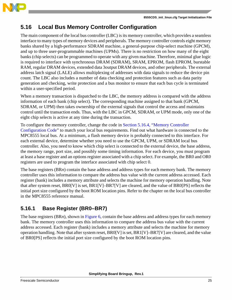
5.16 Local Bus Memory Controller ConfigurationThe main component of the local bus controller (LBC) is its memory controller, which provides a seamless interface to many types of memory devices and peripherals. The memory controller controls eight memory banks shared by a high-performance SDRAM machine, a general-purpose chip-select machine (GPCM), and up to three user-programmable machines (UPMs). There is no restriction on how many of the eight banks (chip selects) can be programmed to operate with any given machine. Therefore, minimal glue logic is required to interface with synchronous DRAM (SDRAM), SRAM, EPROM, flash EPROM, burstable RAM, regular DRAM devices, extended data 3output DRAM devices, and other peripherals. The external address latch signal (LALE) allows multiplexing of addresses with data signals to reduce the device pin count. The LBC also includes a number of data checking and protection features such as data parity generation and checking, write protection and a bus monitor to ensure that each bus cycle is terminated within a user-specified period.
When a memory transaction is dispatched to the LBC, the memory address is compared with the address information of each bank (chip select). The corresponding machine assigned to that bank (GPCM, SDRAM, or UPM) then takes ownership of the external signals that control the access and maintains control until the transaction ends. Thus, with the LBC in GPCM, SDRAM, or UPM mode, only one of the eight chip selects is active at any time during the transaction.
To configure the memory controller, change the code in Section 5.16.4, “Memory Controller Configuration Code” to match your local bus requirements. Find out what hardware is connected to the MPC8555 local bus. At a minimum, a flash memory device is probably connected to this interface. For each external device, determine whether you need to use the GPCM, UPM, or SDRAM local bus controller. Also, you need to know which chip select is connected to the external device, the base address, the memory range, port size, and possibly some timing information. For each device, you must program at least a base register and an options register associated with a chip select. For example, the BR0 and OR0 registers are used to program the interface associated with chip select 0.
The base registers (BRn) contain the base address and address types for each memory bank. The memory controller uses this information to compare the address bus value with the current address accessed. Each register (bank) includes a memory attribute and selects the machine for memory operation handling. Note that after system reset, BR0[V] is set, BR1[V]–BR7[V] are cleared, and the value of BR0[PS] reflects the initial port size configured by the boot ROM location pins. Refer to the chapter on the local bus controller in the MPC8555 reference manual.
5.16.1 Base Register (BR0–BR7)
The base registers (BRn), shown in Figure 6, contain the base address and address types for each memory bank. The memory controller uses this information to compare the address bus value with the current address accessed. Each register (bank) includes a memory attribute and selects the machine for memory operation handling. Note that after system reset, BR0[V] is set, BR1[V]–BR7[V] are cleared, and the value of BR0[PS] reflects the initial port size configured by the boot ROM location pins.

Simplifying Board Bringup, Rev.1
26 Freescale Semiconductor
8555CDS_init_linux.cfg Target Initialization File
Table 4 describes the BRn fields.
Offset 0xC_5000(BR0)0x0_5008(BR1)0x0_5010(BR2)
0x0_5018(BR3)0x0_5020(BR4)0x0_5028(BR5)
0x0_5030(BR6)0x0_5038(BR7)
Access: Read/Write
0 16 17 18 19 20 21 22 23 24 26 27 28 29 30 31
RBA — PS DECC WP MSEL — ATOM — V
W
Reset 0 0 0 0 0 0 0 0 0 0 0 0 0 0 0 0 0 0 0 0 P S 0 0 0 0 0 0 0 0 0 01
1 BR0 has its valid bit set during reset. Thus bank 0 is valid with the port size (PS) configured from external boot ROM configuration pins during reset. All other base registers have all bits cleared to zero during rest.
Figure 6. Base Registers (BR0-BR7)
Table 4. LAWARn Bit Field Descriptions
Bits Name Description
0–16 BA Base address. The upper 17 bits of each register are compared to the address on the address bus to determine if the bus master is accessing a memory bank controlled by the memory controller. Used with the address mask bits ORn[AM]
17–18 — Reserved
19–20 PS Port Size. Specifies the port size of this memory region. For BR0, PS is configured from the boot ROM location pins during reset. For all other banks the value is reset to 00 (port size not defined).00 Reserved01 8-bit10 16-bit11 32-bit
21–22 DECC Specifies the method for data error checking00 Data error checking disabled, but normal parity generation.01 Normal parity generation and checking.10 Read-modify-write parity generation and normal parity checking (32-bit port size only)11 Reserved
23 WP Write protect
0 Read and write accesses are allowed1 Only read accesses are allowed. The memory controller does not assert LCSn on write cycle to
this memory bank. WP is set (if enabled) if a write to this memory bank is attempted and a local bus error interrupt is generated (if enabled), terminating the cycle.
Simplifying Board Bringup, Rev.1
Freescale Semiconductor 27
8555CDS_init_linux.cfg Target Initialization File
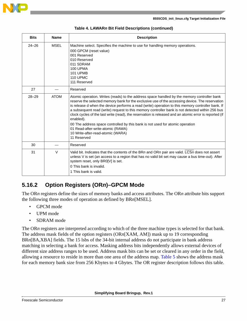
5.16.2 Option Registers (ORn)–GPCM ModeThe ORn registers define the sizes of memory banks and access attributes. The ORn attribute bits support the following three modes of operation as defined by BRn[MSEL].
• GPCM mode
• UPM mode
• SDRAM mode
The ORn registers are interpreted according to which of the three machine types is selected for that bank. The address mask fields of the option registers (ORn[XAM, AM]) mask up to 19 corresponding BRn[BA,XBA] fields. The 15 lsbs of the 34-bit internal address do not participate in bank address matching in selecting a bank for access. Masking address bits independently allows external devices of different size address ranges to be used. Address mask bits can be set or cleared in any order in the field, allowing a resource to reside in more than one area of the address map. Table 5 shows the address mask for each memory bank size from 256 Kbytes to 4 Gbytes. The OR register description follows this table.
24–26 MSEL Machine select. Specifies the machine to use for handling memory operations.
000 GPCM (reset value)001 Reserved 010 Reserved011 SDRAM100 UPMA101 UPMB110 UPMC111 Reserved
27 — Reserved
28–29 ATOM Atomic operation. Writes (reads) to the address space handled by the memory controller bank reserve the selected memory bank for the exclusive use of the accessing device. The reservation is release d when the device performs a read (write) operation to this memory controller bank. If a subsequent read (write) request to this memory controller bank is not detected within 256 bus clock cycles of the last write (read), the reservation is released and an atomic error is reported (if enabled).00 The address space controlled by this bank is not used for atomic operation01 Read-after-write-atomic (RAWA)10 Write-after-read-atomic (WARA)11 Reserved
30 — Reserved
31 V Valid bit. Indicates that the contents of the BRn and ORn pair are valid. LCSn does not assert unless V is set (an access to a region that has no valid bit set may cause a bus time-out). After system reset, only BR0[V] is set.
0 This bank is invalid.1 This bank is valid.
Table 4. LAWARn Bit Field Descriptions (continued)
Bits Name Description

Simplifying Board Bringup, Rev.1
28 Freescale Semiconductor
8555CDS_init_linux.cfg Target Initialization File
Figure 7 shows the bit fields for ORn when the corresponding BRn[MSEL] selects the GPCM machine.
Table 5. Memory Sizes Bank Sizes in Relation to Address Mask
Bits 17–18 AM Memory Bank SIze
11 0000_0000_0000_0000_0 4 Gbytes
11 1000_0000_0000_0000_0 2 Gbytes
11 1100_0000_0000_0000_0 1 Gbytes
11 1110_0000_0000_0000_0 512 Mbytes
11 1111_0000_0000_0000_0 256 Mbytes
11 1111_1000_0000_0000_0 128 Mbytes
11 1111_1100_0000_0000_0 64 Mbytes
11 1111_1110_0000_0000_0 32 Mbytes
11 1111_1111_0000_0000_0 16 Mbytes
11 1111_1111_1000_0000_0 8 Mbytes
11 1111_1111_1100_0000_0 4 Mbytes
11 1111_1111_1110_0000_0 2 Mbytes
11 1111_1111_1111_0000_0 1 Mbytes
11 1111_1111_1111_1000_0 512 Kbytes
11 1111_1111_1111_1100_0 256 Kbytes
11 1111_1111_1111_1110_0 128 Kbytes
11 1111_1111_1111_1111_0 64 Kbytes
11 1111_1111_1111_1111_1 32 Kbytes
Offset 0xC_5004(OR0)0x0_500C(OR1)
0x0_5014(OR2)0x0_501C(OR3)0x0_5024(OR4)
0x0_502C(OR5)0x0_5034(OR6)0x0_503C(OR7)
Access: Read/Write
0 16 17 18 19 20 21 22 23 24 25 26 27 28 29 30 31
RAM — BCTLD CSNT ACS XACS SCY SETA TRLX EHTR EAD
W
Reset 0 0 0 0 0 0 0 0 0 0 0 0 0 0 0 0 0 0 0 0 1 1 1 1 1 1 1 1 0 1 1 11
Reset All zeros1 OR0 has this value set during reset (GPCM is the default control machine for all banks coming out of reset). All other option
registers have all bits cleared.
Figure 7. Option Registers (ORn) – GPCM Mode

Simplifying Board Bringup, Rev.1
Freescale Semiconductor 29
8555CDS_init_linux.cfg Target Initialization File
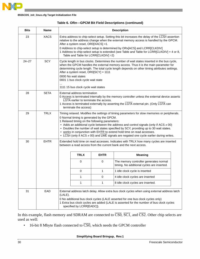
Table 6 describes the ORn fields for GPCM mode.
Table 6. ORn—GPCM Bit Field Descriptions
Bits Name Description
0–16 AM GPCM address mask. Masks corresponding BRn bits. Masking address bits independently allows external devices of different size address ranges to be used. Address mask bits can be set or cleared in any order in the field, allowing a resource to reside in more than one area of the address map.0 Corresponding address bits are masked.1 Corresponding address bits are used in the comparison between base and transaction
address.
17–18 — Reserved
19 BCTLD Buffer control disable. Disables assertion of LBCTL during access to the current memory bank.0 LBCTL is asserted upon access to the current memory bank.1 LBCTL is not asserted upon access to the current memory bank.
20 CSNT Chip select negation time. Determines when LCSn and LWE are negated during an external memory write access handled by the GPCM, provided that ACS ≠ 00 (when ACS = 00, only LWE is affected by the setting of CSNT). This helps meet address/data hold times for slow memories and peripherals.0 LCSn and LWE are negated normally.1 LCSn and LWE are negated earlier depending on the value of LCCR[CLKDIV]
21–22 ACS Address to chip-select setup. Determines the delay of the LCSn assertion relative to the address change when the external memory access is handled by the GPCM. At system reset, OR0[ACS] = 11.
LCRR[CLKDIV] CSNT Meaning
x 0 LCSn and LWE are negated normally
2 1 LCSn and LWE are negated normally
4 or 8 1 LCSn and LWE are negated quarter of a bus clock cycle earlier.
LCRR[CLKDIV] CSNT Meaning
x 00 LCSn is output at the same time as the address lines. Note that this overrides the value of CSNT such that CSNT = 0
01 Reserved
2 10 LCSn is output a half bus clock cycle after the address lines.
11 LCSn is output a half bus clock cycle after the address lines.
4 or 8 10 LCSn is output a quarter bus clock cycle after the address lines
LCSn is output a half bus clock cycle after the address lines
Simplifying Board Bringup, Rev.1
30 Freescale Semiconductor
8555CDS_init_linux.cfg Target Initialization File
In this example, flash memory and SDRAM are connected to CS0, SC1, and CS2. Other chip selects are used as well:
• 16-bit 8 Mbyte flash connected to CS0, which needs the GPCM controller
23 XACS Extra address to chip-select setup. Setting this bit increases the delay of the LCSn assertion relative to the address change when the external memory access is handled by the GPCM. After a system reset, OR0[XACS] =1.0 Address to chip-select setup is determined by ORx[ACS] and LCRR[CLKDIV]1 Address to chip-select setup is extended (see Table and Table for LCRR[CLKDIV] = 4 or 8,
Table and Table for LCRR[CLKDIV] =2)
24–27 SCY Cycle length in bus clocks. Determines the number of wait states inserted in the bus cycle, when the GPCM handles the external memory access. Thus it is the main parameter for determining cycle length. The total cycle length depends on other timing attributes settings. After a system reset, OR0[SCY] = 1111
0000 No wait states0001 1 bus clock cycle wait state...1111 15 bus clock cycle wait states
28 SETA External address termination0 Access is terminated internally by the memory controller unless the external device asserts
LGTA earlier to terminate the access.1 Access is terminated externally by asserting the LGTA external pin. (Only LGTA can
terminate the access)
29 TRLX Timing relaxed. Modifies the settings of timing parameters for slow memories or peripherals.
0 Normal timing is generated by the GPCM.1 Relaxed timing on the following parameters: • Adds an additional cycle between the address and control signals (only if ACS ≠ 00) • Doubles the number of wait states specified by SCY, providing up to 30 wait states. • works in conjunction with EHTR to extend hold time on read accesses. • LCSn (only if ACS ≠ 00) and LWE signals are negated one cycle earlier during writes.
30 EHTR Extended hold time on read accesses. Indicates with TRLX how many cycles are inserted between a read access from the current bank and the next access.
31 EAD External address latch delay. Allow extra bus clock cycles when using external address latch (LALE).0 No additional bus clock cycles (LALE asserted for one bus clock cycles only)1 Extra bus clock cycles are added (LALE is asserted for the number of bus clock cycles
specified by LCRR[EADC]).
Table 6. ORn—GPCM Bit Field Descriptions (continued)
Bits Name Description
TRLX EHTR Meaning
0 0 The memory controller generates normal timing. No additional cycles are inserted.
0 1 1 idle clock cycle is inserted
1 0 4 idle clock cycles are inserted
1 1 8 idle clock cycles are inserted.

Simplifying Board Bringup, Rev.1
Freescale Semiconductor 31
8555CDS_init_linux.cfg Target Initialization File
• 16 bit 8 Mbyte flash connected to CS1, which needs the GPCM controller
• SDRAM connected to CS2, which needs the SDRAM controller
Create a list of all devices connected to local bus interface and the associated properties. For simplicity, just program the interface for the flash memory, which should be connected to CS0 at a minimum. Program the correct values into CS0 and BR0 and then comment out the remaining configurations of BR1/CS1, BR2/CS2, BR3/CS3, and BR7/CS7.
Two other registers that must be programmed are LBCR (see Table 7) and LCRR. In this example, most of the default values are used.
5.16.3 Clock Ratio RegisterThe clock ratio register sets the system (CCB) clock to the LBC bus frequency ratio. It also provides configuration bits for extra delay cycles for address and control signals.
Table 8 describes the LCRR fields
Table 7. LBCR
Bits Name Description
16–23 BMT Bus monitor timing. Defines the bus monitor time-out period. Clearing BMT (reset value) selects the maximum count of 2048 bus clock cycles. For non-zero values of BMT, the number of LCLK clock cycles to count down before a time-out error is generated is given by: bus cycles = BMTx8. Apart from BMT = 0x00, the minimum value of BMT is 5, corresponding with 40 bus cycles. Shorter time-out may result in spurious errors during SDRAM operation.
24–31 — Reserved
Offset 0x0_50D4 Access: Read/Write
0 1 2 3 4 5 6 7 8 13 14 15 16 27 28 31
RDBYP — BUFCMDC — ECL — EADC — CLKDIV
W
Reset 1 0 0 0 0 0 0 0 0 0 0 0 0 0 0 0 0 0 0 0 0 0 0 0 0 0 0 0 1 0 0 0
Figure 5-8. Clock Ratio Register (LCRR)
Table 8. LCRR
Bits Name Description
0 DBYP DLL bypass. Set when using low bus clock frequencies if the DLL cannot lock. In DLL bypass mode, incoming data is captured in the middle of the bus clock cycle.0 The DLL is enabled.1 The DLL is bypassed.
1 — Reserved
2–3 BUFCMDC Additional delay cycles for SDRAM control signals. Defines the number of cycles to be added for each SDRAM command when LSDMR[BUFCMD] = 100 401 110 211 3

Simplifying Board Bringup, Rev.1
32 Freescale Semiconductor
8555CDS_init_linux.cfg Target Initialization File
5.16.4 Memory Controller Configuration CodeTo configure the memory controller, change the code presented in this section to match your local bus requirements.
################################################################################### configure local bus memory controller ##################################################################################
# CS0 - Flash Bank #0writemem.l 0xe0005000 0xFF801001 # BR0 base address at 0xFF800000, port size 16 bit, GPCM, validwritemem.l 0xe0005004 0xFF806E61 # OR0 8 Mbyte flash size
#################################################################################### CS1 - Flash Bank #1writemem.l 0xe0005008 0xFF001001 # BR1 base address at 0xFF000000, port size 16 bit, GPCM, validwritemem.l 0xe000500C 0xFF806E61 # OR1 8MB flash size
#################################################################################### CS2 - Local SDRAMwritemem.l 0xe0005010 0xf0001861 # BR2writemem.l 0xe0005014 0xfc006901 # OR2
####################################################################################
# CS3 - CADMUSwritemem.l 0xe0005018 0xF8000801 # BR3 base address at 0xF8000000writemem.l 0xe000501C 0xFF000FF7 # OR3 16 Mbyte ####################################################################################
4–5 — Reserved
6–7 ECL Extended CAS latency. Determines the extended CAS latency for SDRAM accesses when LSDMR[CL] = 0
8–13 — Reserved
14–15 EADC External address delay cycles. Defines the number of cycles for the assertion of LALE. Note that LALE negates prior to the end of the final local bus clock as controlled by LBCR[AHD]00 401 110 211 3
16–27 — Reserved
28–31 CLKDIV System (CCB) clock divider. Sets the frequency ratio between the system (CCB) clock and the memory bus clock. Only the values shown in the table below are allowed.0000–0001 Reserved0010 20011 Reserved0100 40101–0111 Reserved1000 81001–1111 Reserved
Table 8. LCRR (continued)
Bits Name Description

Simplifying Board Bringup, Rev.1
Freescale Semiconductor 33
8555CDS_init_linux.cfg Target Initialization File
writemem.l 0xe0005038 0xf9001801 # BR7writemem.l 0xe000503C 0xfff00ff7 # OR7
# CS7
################################################################
################################################################
# the following line enables the local bus and uses the default values.# writemem.l 0xe00050d0 0x00000000 LBCR (configuration register)
################################################################
##############################################################
# the next line uses default values except for EADC (3 delay cycles) and for CLKDIV (divide by# 4). These values should work for most flash memory devices as they give more margin for timing.
writemem.l 0xe00050d4 0x80030004 # LCRR
################################################################
################################################################
#The next 16 lines of code are for the SDRAM, which is on the local bus. However this section#of code should be commented out because we want to configure only flash memory on the board.
writemem.l 0xe00050a4 0x20000000 # LSRTwritemem.l 0xe0005094 0x0063b723 # LSDMRwritemem.l 0xe0005094 0x2863b723 # LSDMR - init sdram sequencewritemem.l 0xC0000000 0x000000ff #writemem.l 0xe0005094 0x0863b723 #writemem.l 0xC0000000 0x000000ff #writemem.l 0xC0000000 0x000000ff #writemem.l 0xC0000000 0x000000ff #writemem.l 0xC0000000 0x000000ff #writemem.l 0xC0000000 0x000000ff #writemem.l 0xC0000000 0x000000ff #writemem.l 0xC0000000 0x000000ff #writemem.l 0xC0000000 0x000000ff #writemem.l 0xe0005094 0x1863B723 #writemem.l 0xC00000cc 0x000000ff #writemem.l 0xe0005094 0x4063B723 #
################################################################
5.17 Set up Interrupt Handlers in DDRInterrupt processing begins with an exception that occurs due to external conditions, errors, or program execution problems. When the exception occurs, the processor checks to verify that interrupt processing is enabled for that exception. If it is enabled, the interrupt causes the state of the processor to be saved in the appropriate registers, and it prepares to start executing the interrupt handler (interrupt service routine) at the associated vector address for that exception. When the handler is executing, the implementation may need to check one or more bits in the exception syndrome register (ESR) or the SPEFSCR, depending on the exception, to verify the specific cause of the exception and take appropriate action.
Each interrupt has an associated interrupt vector address obtained by concatenating the IVPR prefix value with the address offset in the associated IVOR (that is, IVPR[32–47]||IVORn[48–59]||0b0000). The

Simplifying Board Bringup, Rev.1
34 Freescale Semiconductor
8555CDS_init_linux.cfg Target Initialization File
resulting address is that of the instruction to execute when that interrupt occurs. IVPR and IVOR values are indeterminate on reset and the system software uses mtspr to initialize them.
In our target initialization file, the interrupt vectors are at the top of DDR memory (that is, 0x00000000). To place the interrupt vectors at another base address, write to bits 32–47 of the IVPR. The offset registers (IVOR[0–35]) are standard and do not need to be changed.
If an exception occurs during board bringup, the processor jumps to the interrupt handler and there should at least be an infinite loop at each interrupt handler, which is accomplished by writing the value 0x4800_0000 at the address of each interrupt handler. Otherwise, the processor enters an unknown state. If the infinite loops are present and an exception occurs, the code goes into an infinite loop and you can use the CodeWarrior debugger to determine the source of the exception.
In our configuration file the value of 0x4800_0000 is written only to 0x00000700 and 0x00001500. However, we recommend that you write it to all interrupt vectors. There are 18 interrupt handlers to set up by writing 0x4800_0000 to all interrupt handler locations (0x0000_0100, 0x0000_0200, and so on).
5.17.1 Interrupt Vector Prefix Register (IVPR)
5.17.2 Interrupt Vector Offset Register (IVORn)
#################################################################################### interrupt vector initialization; interrupt vectors in DDR#################################################################################### writereg IVPR 0x00000000 # IVPR (default reset value)
Offset Access: Read/Write
32 47 48 63
RInterrupt vector prefix —
W
Reset All zeros
SPR SPR 63
Figure 9. Interrupt Vector Prefix Register (IVPR)
Offset Access: Read/Write
32 47 48 59 60 63
R— Interrupt vector —
W
Reset All zeros
SPR
Figure 10. Interrupt Vector Offset Registers (IVORn)
5.17.3 Interrupt Vector Initialization CodeThe code in this section shows 18 IVORn values. Any exception within the processor is mapped to a unique IVOR and therefore to a unique interrupt handler.

Simplifying Board Bringup, Rev.1
Freescale Semiconductor 35
8555CDS_init_linux.cfg Target Initialization File
# interrupt vector offset registers writespr 400 0x00000100# IVOR0 - critical inputwritespr 401 0x00000200# IVOR1 - machine checkwritespr 402 0x00000300# IVOR2 - data storagewritespr 403 0x00000400# IVOR3 - instruction storagewritespr 404 0x00000500# IVOR4 - external inputwritespr 405 0x00000600# IVOR5 - alignmentwritespr 406 0x00000700# IVOR6 - programwritespr 408 0x00000c00# IVOR8 - system callwritespr 410 0x00000900# IVOR10 - decrementerwritespr 411 0x00000f00# IVOR11 - fixed-interval timer interruptwritespr 412 0x00000b00# IVOR12 - watchdog timer interruptwritespr 413 0x00001100# IVOR13 - data TLB errorwritespr 414 0x00001000# IVOR14 - instruction TLB errorwritespr 415 0x00001500# IVOR15 - debugwritespr 528 0x00001600# IVOR32 - SPE-APU unavailablewritespr 529 0x00001700# IVOR33 - SPE-floating point data exceptionwritespr 530 0x00001800# IVOR34 - SPE-floating point round exception
writespr 531 0x00001900# IVOR35 - performance monitor# put a valid opcode at debug and program exception vector address# Write “0x4800_0000”to all interrupt handler locations (0x0000_0100, #0x0000_0200,…). In this configuration file “0x4800_0000” is only written to #0x00000700 and 0x00001500 however we suggest to write it to all interrupt vectors.
writemem.l 0x00000700 0x48000000writemem.l 0x00001500 0x48000000#
5.18 Activate Debug Interrupt and Enable SPUThe following lines ensure that the debug interrupt and SPU are enabled.
#################################################################################### activate debug interrupt and enable SPU####################################################################################writereg MSR 0x02000200####################################################################################
5.19 Set Up L1 CacheOur target initialization file enables the L1 cache. However, it is easier to bring up a board with caches disabled. Therefore, we recommend omitting the next two lines by commenting them so that the L1 cache remains disabled.
#################################################################################### enable L1 cache####################################################################################
# It is easier to bring up a board with the caches disabled. We recommend omitting the next two# lines by adding a # before them.
# enable data cachewritespr 1010 0x00000001 # L1CSR0

Simplifying Board Bringup, Rev.1
36 Freescale Semiconductor
8555CDS_init_linux.cfg Target Initialization File
# enable instruction cachewritespr 1011 0x00000001 # L1CSR1#
###################################################################################
5.20 Time Base EnableCodeWarrior uses the time base, so it must be enabled.
#################################################################################### time base enable####################################################################################writespr 1008 0x00004000 # HID0#######################################################################
5.21 UART ConfigurationThe following code configures UART0: receive data interrupt enabled, character length set to 8 bits, divisor set to 90, RTS asserted, transmitter/receiver FIFO cleared, and transmitter/receiver enabled.
#################################################################################### the serial configuration UART# enable received data available interrupt####################################################################################writemem.b 0xe0004501 0x01writemem.b 0xe0004503 0x83writemem.b 0xe0004500 0x90writemem.b 0xe0004501 0x00writemem.b 0xe0004503 0x03writemem.b 0xe0004504 0x03writemem.b 0xe0004502 0x07sleep 0x1000####################################################################################
5.22 CodeWarrior Debugger ConfigurationThis section enables the trap debug event and sets the program counter and stack pointer.
#################################################################################### CodeWarrior debugger settings. #####################################################################################Trap debug event enablewritereg DBCR0 0x41000000
# set the PC at the reset address (for debug-->connect)writereg PC 0xfffffffc# for debugging starting at program entry point when stack is not initializedwritereg SP 0x0000000F####################################################################################

Simplifying Board Bringup, Rev.1
Freescale Semiconductor 37
Conclusion
6 ConclusionSection 4, “Flow of Target Initialization File familiarizes you with the overall flow of the target initialization file. Section 3, “Syntax and Command Set,” examines the syntax and command sets of the target initialization file. Section 5, “8555CDS_init_linux.cfg Target Initialization File analyzes each section of this file, identifying the sections to modify for your application. At this point, you should be able to modify the CodeWarrior target initialization file to configure the following modules:
• L1 Instruction and Data cache
• L2 cache/SRAM
• Memory map through local access windows (LAWs)
• Memory management unit (MMU: TLBs)
• Flash memory devices connected to the local bus
• DDR memory controller
• Exception handlers in DDR
7 Revision HistoryTable 9 presents a revision history of this document.
Table 9. Revision History for AN3366
Revision Date Description of Changes
1 5/2007 Page 14. First two bullets on that page are corrected. The first bullet is changed from TLB0 to TLB1, with the same description. The second bullet is changed to from TLB1 to TLB0, with the same description.
0 4/2007 Initial release.

Simplifying Board Bringup, Rev.1
38 Freescale Semiconductor
Revision History
THIS PAGE INTENTIONALLY LEFT BLANK

Simplifying Board Bringup, Rev.1
Freescale Semiconductor 39
Revision History
THIS PAGE INTENTIONALLY LEFT BLANK

Document Number: AN3366Rev.105/2007
Information in this document is provided solely to enable system and software
implementers to use Freescale Semiconductor products. There are no express or
implied copyright licenses granted hereunder to design or fabricate any integrated
circuits or integrated circuits based on the information in this document.
Freescale Semiconductor reserves the right to make changes without further notice to
any products herein. Freescale Semiconductor makes no warranty, representation or
guarantee regarding the suitability of its products for any particular purpose, nor does
Freescale Semiconductor assume any liability arising out of the application or use of
any product or circuit, and specifically disclaims any and all liability, including without
limitation consequential or incidental damages. “Typical” parameters which may be
provided in Freescale Semiconductor data sheets and/or specifications can and do
vary in different applications and actual performance may vary over time. All operating
parameters, including “Typicals” must be validated for each customer application by
customer’s technical experts. Freescale Semiconductor does not convey any license
under its patent rights nor the rights of others. Freescale Semiconductor products are
not designed, intended, or authorized for use as components in systems intended for
surgical implant into the body, or other applications intended to support or sustain life,
or for any other application in which the failure of the Freescale Semiconductor product
could create a situation where personal injury or death may occur. Should Buyer
purchase or use Freescale Semiconductor products for any such unintended or
unauthorized application, Buyer shall indemnify and hold Freescale Semiconductor
and its officers, employees, subsidiaries, affiliates, and distributors harmless against all
claims, costs, damages, and expenses, and reasonable attorney fees arising out of,
directly or indirectly, any claim of personal injury or death associated with such
unintended or unauthorized use, even if such claim alleges that Freescale
Semiconductor was negligent regarding the design or manufacture of the part.
How to Reach Us:
Home Page: www.freescale.com
Web Support: http://www.freescale.com/support
USA/Europe or Locations Not Listed: Freescale Semiconductor, Inc.Technical Information Center, EL5162100 East Elliot Road Tempe, Arizona 85284 +1-800-521-6274 or+1-480-768-2130www.freescale.com/support
Europe, Middle East, and Africa:Freescale Halbleiter Deutschland GmbHTechnical Information CenterSchatzbogen 781829 Muenchen, Germany+44 1296 380 456 (English) +46 8 52200080 (English)+49 89 92103 559 (German)+33 1 69 35 48 48 (French) www.freescale.com/support
Japan: Freescale Semiconductor Japan Ltd. HeadquartersARCO Tower 15F1-8-1, Shimo-Meguro, Meguro-ku Tokyo 153-0064Japan 0120 191014 or+81 3 5437 [email protected]
Asia/Pacific: Freescale Semiconductor Hong Kong Ltd. Technical Information Center2 Dai King Street Tai Po Industrial Estate Tai Po, N.T., Hong Kong +800 2666 [email protected]
For Literature Requests Only:Freescale Semiconductor
Literature Distribution Center P.O. Box 5405Denver, Colorado 80217 +1-800 441-2447 or+1-303-675-2140Fax: +1-303-675-2150LDCForFreescaleSemiconductor
@hibbertgroup.com
Freescale™, the Freescale logo, and PowerQUICC are trademarks of Freescale Semiconductor, Inc. CodeWarrior is a trademark or registered trademark of Freescale Semiconductor, Inc. in the United States and/or other countries. The Power Architecture and Power.org word marks and the Power and Power.org logos and related marks are trademarks and service marks licensed by Power.org. All other product or service names are the property of their respective owners.
© Freescale Semiconductor, Inc., 2007. All rights reserved.