Simplification of the Mechanical Design of Drives with the ... · the limits of responsibility...
16
PROCEEDINGS 11-15 September 2006 FACULTY OF ELECTRICAL ENGINEERING AND INFORMATION SCIENCE INFORMATION TECHNOLOGY AND ELECTRICAL ENGINEERING - DEVICES AND SYSTEMS, MATERIALS AND TECHNOLOGIES FOR THE FUTURE Startseite / Index: http://www.db-thueringen.de/servlets/DocumentServlet?id=12391 51. IWK Internationales Wissenschaftliches Kolloquium International Scientific Colloquium
Transcript of Simplification of the Mechanical Design of Drives with the ... · the limits of responsibility...

PROCEEDINGS 11-15 September 2006 FACULTY OF ELECTRICAL ENGINEERING AND INFORMATION SCIENCE
INFORMATION TECHNOLOGY AND ELECTRICAL ENGINEERING - DEVICES AND SYSTEMS, MATERIALS AND TECHNOLOGIES FOR THE FUTURE Startseite / Index: http://www.db-thueringen.de/servlets/DocumentServlet?id=12391
51. IWK Internationales Wissenschaftliches Kolloquium
International Scientific Colloquium

Impressum Herausgeber: Der Rektor der Technischen Universität llmenau Univ.-Prof. Dr. rer. nat. habil. Peter Scharff Redaktion: Referat Marketing und Studentische
Angelegenheiten Andrea Schneider Fakultät für Elektrotechnik und Informationstechnik Susanne Jakob Dipl.-Ing. Helge Drumm Redaktionsschluss: 07. Juli 2006 Technische Realisierung (CD-Rom-Ausgabe): Institut für Medientechnik an der TU Ilmenau Dipl.-Ing. Christian Weigel Dipl.-Ing. Marco Albrecht Dipl.-Ing. Helge Drumm Technische Realisierung (Online-Ausgabe): Universitätsbibliothek Ilmenau Postfach 10 05 65 98684 Ilmenau
Verlag: Verlag ISLE, Betriebsstätte des ISLE e.V. Werner-von-Siemens-Str. 16 98693 llrnenau © Technische Universität llmenau (Thür.) 2006 Diese Publikationen und alle in ihr enthaltenen Beiträge und Abbildungen sind urheberrechtlich geschützt. Mit Ausnahme der gesetzlich zugelassenen Fälle ist eine Verwertung ohne Einwilligung der Redaktion strafbar. ISBN (Druckausgabe): 3-938843-15-2 ISBN (CD-Rom-Ausgabe): 3-938843-16-0 Startseite / Index: http://www.db-thueringen.de/servlets/DocumentServlet?id=12391

51. Internationales Wissenschaftliches Kolloquium
Simplification of the Mechanical Design of Drives with the Application of Direct Drives
Peter-Klaus Budig
September 11 - 15, 2006 Technische Universität Ilmenau
Prof. Dr. sc. techn. Dr.h. c. Peter- Klaus Budig EAAT GmbH Chemnitz
Annaberger Str. 231 G – 09120 Chemnitz
Tel. ..49 371 5301911, Fax. .. 493715301913 e-mail : [email protected]
Abstracts: A direct drive means a gearless mechanical con-
nection between motor and machine. This principle can be
realized with revolving and linear motors as well.
The gearless design has advantages for the simplification of
the system as well as for the dynamic performance of the
drive. Last but not least the energy consumption is reduced.
The simplification leads to the integration of actuator and
machine components. This brings a cost reduction as well as
a reduction of the maintenance costs. Some practical appli-
cations are discussed.
I. INTRODUCTION
In many countries 60 % of the electro- energy is
changed by electrical drives in mechanical energy. The
electrical drive are able adapt speed and torque very tight
to the machines or process need. Thus energy can be
saved in an amount of several percents to 30%. This is
important for the global economy and means a high re-
sponsibility of the drive engineers to save energy.
II. STRUCTURE OF A DRIVE- SYSTEM
As Fig. 1 shows the classic drive has a gear- box be-
tween the motor and machine. Even more it can be any
mechanism to perform revolving motion to liner motion.
In the structure there are power- loss sources in the mo-
tor, the gear box or mechanism and finely in the machine.
Similar it is with the moments of inertia. The energy is at
least twice converted.
Much more simple is the system using a direct drive.
That one is characterized by the direct connection of mo-
tor and machine. According to this there is at least one
source less of losses and of inertia.
The mechanical gear is not necessary as well as a
mechanisms for changing revolving motion to linear mo-
tion are not needed.
Less losses leads to less energy- costs and less inertia
gives a higher dynamic performance. But there are some
more financial advantages:
- less space - less investigation amount
- less noise
- less amount of maintenance
- no costs for the gear- box or the mechanism.
III. DRIVE STRUCTURE
As shown in Fig. 2 there is the direct drive structure of
a revolving and a linear drive. Revolving drives mostly
using low speed and high torque. Now there are many
producer are offering so called “torque motors” which are
designed for the mentioned condition. Similar it is in a
linear drive- system. There is an interesting exception in
the field of revolving drives the magnetically suspended
spindle. Here are used extremely high speeds like several
103 rpm (Fig. 3).
A more detailed introduction to a linear direct drive
shows Fig. 4. Here are compared a linear drive of a ma-
chine- tool with a drive with a ball- screw drive. It is to

be seen the last one has much more elements of elasticity
and much more mechanical components. In these compo-
nents are hidden damping performance as well as torsion-
effects. They are a additional source of oscillations.
Therefore the diff. equation becomes of a higher order
has additional resonance effects as well as a reduction of
the response time of the drive. Of high importance is that
in a direct drive there is no back- lash which influences
the dynamic performance negative.
One more system design is of interest the combination
of a revolving and a linear motor as it shows Fig. 5. Here
it is necessary to design the revolving motor in that way
that its rotor can be moved with the linear motor without
to leave the stator boring.
IV. SYNCHRONOUS OR ASYNCHRONOUS MOTOR
The power distribution gives Fig. 6 for both motor-
types. The asynchronous motor has the disadvantage of
the rotor losses s x Pδ. On the other hand the synchronous
motor may have additions eddy- current- losses in the
surface of the permanent- magnets. Since the speed of a
torque- motor is rather low these losses are to be ne-
glected. The synchronous motors are mostly not fitted
with a exciter- system for the magnetic field. They have
permanent- magnets according to Fig. 7. Torque motors
have surface- magnets. They can have a shaped configu-
ration or there are composed of small strips.
Since the synchronous machine does not need an exci-
tation the power per volume is higher than in an asyn-
chronous machine (see Fig. 8).
In the air- gap of the synchronous machine there is are
the permanent magnets as well as the stator- winding. Its
current coverage drives a magnetic field strength perpen-
dicular to the machines d- axis. Thus the magnetic induc-
tion of the permanent magnets is decreased at the one
side and increased at the other side of the pole. If the
magnetic field- strength is big enough a demagnetisation
can occur (Fig. 9).
As the vector diagram of currents and voltages show
the speed of a synchronous machine is limited by the
terminal voltage. According to equ. 2 and Fig. 10 is:
Us = Up + I ( Rs + j ω ls ) ( 2 )
For increasing the speed it is demanded for a weaken-
ing of the magnetic fields and according to this of the
voltage Up. For this the component Isd is needed. Now
there is a decreasing of the magnetic field and the above
mentioned voltage. Now speed above the normal rated
value becomes possible. But there is a danger. If the ter-
minal- voltage fails suddenly there now is induced a volt-
age UP is:
Upd = Up x nmax / nrated.
Its value can is much higher than the terminal voltage.
Thus the maximum permissible voltage of the inverters
power- components is exceeded and they have a break
through – they are damaged.
V. OPERATION DIAGRAM OF THE SYNCHRONOUS MOTOR
Fig.11 shows the operation- diagram. There is plotted
torque above speed.
Tc = continuous torque, according to the iron- losses it
decreases with increasing speed.
Tmax = the maximum torque, can be used only for a
short time. It is limited by the maximum permissible cur-
rent of the inverter.
Demagnetising limit. As already discussed demagneti-
sation can happen if the current becomes too high.
Limitation by the inverter- voltage. In between con-
tinuous torque and maximum torque there is the range of
short- time operation.
VI. REVOLVING DIRECT DRIVES
Two realised examples are shown in Fig. 11. In both
cases is well to be seen the integration of mechanical and
electromagnetic components. This is the remarkable ef-
fect of the direct drive concept. Now there is a change of

the limits of responsibility between machine- engineers
and drive engineers.
Next it is remarkable that the mechanical bearing for
both of the partners is the same. This shows the effect of
simplification.
The second picture shows the integration of the me-
chanical bearing in the magnetic circuit of the motor. The
outside bearing ring is extended in that way that now it
has the double- function – part of the bearing and mag-
netic rotor iron. It was proved that there is no influence
of the magnetic field lines to the iron- bearing balls.
Table 1 gives a survey of realized torque motors. This
list will be extended in the next time for motors with a
torque in the range of 14 000 Nm till 16 000 Nm. Fig. 13
shows the photo of a rotor and a stator
The combination of linear- and revolving- motor shows
Fig. 14.
VII. LINEAR DIRECT DRIVES
The primary and secondary of typical motor- design of
linear motors is shown in Fig. 15, 16 and 17. There are
flat motors with iron at the stator and secondary as well
and even more there is a iron- less stator.
The drive of a tower with a weight of 10 000 kg and a
high position accuracy shows Fig. 18. The Components
of a spherical motor shows Fig. 19. Its Thrust is 1 New-
ton and the resolution in the range of 1 000 Hz is 0,0002°.
It was designed for space application.
VIII. SUMMERY
Direct drives are important for the future of the electri-
cal drives they offer new performance under the point of
view like commercial consideration, simplification of the
structure of the drive system, dynamic performance of the
drive. Last but not least there are advantages for the ap-
plication by lest space, less noise, less maintenance, less
wearing. Thus the applicant can save money.

drive with gearbox
motor
gear- box
process
Pm2 n2(t) M2(t)
Pm n (t)
Pel
Pm1 n1(t) M1(t)
losses: PLoss motor PLoss gearbox PLoss process moment of inertia: JMotor JGerbox JProcess
direct drive
motor
process Pel
Pm v(t) M(t)
Pm n (t)
losses: PLoss motor PLoss process moment of inertia: JMotor JProcess
Fig. 1. Comparsion of drive systems
motor process
process
stator of the linear- motor
secondary of the linear- motor
Revolving motor
Linear motor
Fig. 2. Direct drive

F
i
Elektromagnet
Stellen
Regeln
Messen
setting
adjust
measure
Fig. 3a. Magnetic bearing. Principle

milling spindlespeed: 50.000 min-1
power: 50 kW radial force : 2.000 N axial force: 1.000 N
grinding spindle speed: 8.000 min-1 (max.) power: 4,8 kW TTV (total thickness variation) > 2 micrometer
polishing spindle speed: 1000 min-1 power: 100 W motion in x, y and z- direction
Fig. 3b. Magnetic bearing. Applications
linear motor screw- ball drive
table
position measuring system
coupling
screwball spindle
linear motor
revolv. motor
sensor
screw- ball base
fundament
Fig. 4. Comparison of direct- drive and screw- ball drive

revolving motor linear motor
torque: 30/120 Nm; speed: 216 min-1
stroke: 50mm; thrust: 320/1000 N
Fig. 5. Combination of linear- and revolving drive
Asynchronmaschine Synchronmaschine
Pcu Pcu
PmPm
Pδ
Pll
PelPel
Pll
Pδ
Pme Pme
Pv2 = s ⋅Pδ
Pv2
Pme = Pδ (1- s)
Asynchronmaschine Synchronmaschine
Pcu Pcu
PmPm
Pδ
Pll
PelPel
Pll
Pδ
Pme Pme
Pv2 = s ⋅Pδ
Pv2
Pme = Pδ (1- s)
asynchronous motor synchronous motor
Fig. 6. Power and losses

• surface magnets • embedded magnets with radial magnetization • embedded magnets with tangetial magnetization
Fig. 7. Permanentmagnets of a 4- pole machine
Specific thrust
synchronous machine
asynchronous machine
Fig. 8. Specific thrust
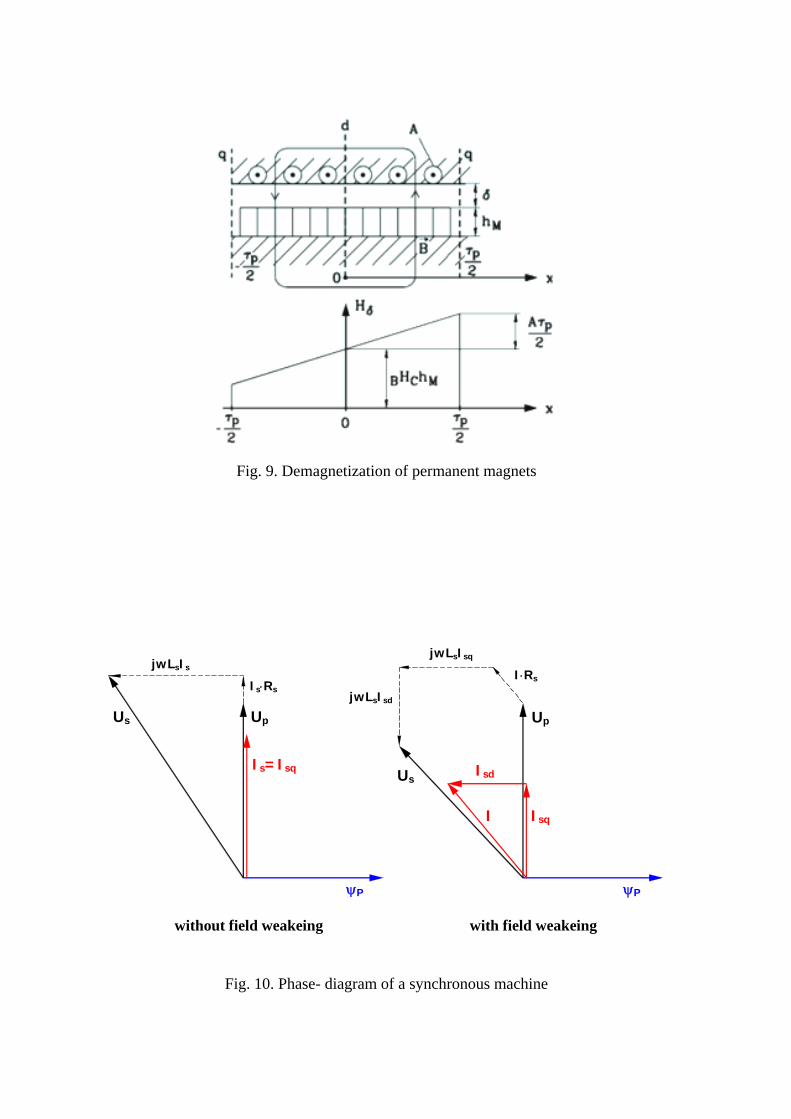
Fig. 9. Demagnetization of permanent magnets
ψP
Is=Isq
Isq
Isd
I
Us
ψP
Us Up
jwLsIsq
jwLsIsd
I⋅RsIs⋅Rs
jwLsIs
Up
without field weakeing with field weakeing
Fig. 10. Phase- diagram of a synchronous machine

demagnetization limit inverter current limit
short time operation
continuous operation
inverter voltage limit
influenced by iron- losses
const
Fig. 11. Operation diagram
Teller
Gehäuse
Rotor
Stator
Magnete
Meßsystem
Fuß
Lagerbearing
magnets
rotor
measuring system
table
stator
frame
foot
Gestell
Festeller
Stator
Magnete
MeßsystemLager
Stator
Gestell
Festeller
Stator
Magnete
MeßsystemLager
Stator
bearing
stator
stator
fixed table
mesuring system
magnets frame
Fig. 12. Realized drive with torque motor

stator with cooling jack bearing- ring with permanent- magnets
Fig. 13. Photo of components of a torque motor
Fig. 14. Combination of revolving and linear direct drive

Secondary unit
Secondary unit
Primary unitPrimary unit
Flat three-phase linear motor
Cylindrical linear motor
Fig. 15. Linear motor
Permanent magnet
Iron
Carbon fibre compound Rotor of a Flat Synchronous Linear Motor
Rotor of a Cylindrical Synchronous Linear Motor
Fig. 16. Secondary of linear motors

magnetic system with joke
length of primary
stroke
Fig. 17. Ironless flat linear motor
weight 10000 kg moment of inertia 32400 kgm² max. torque 3840 Nm speed 0,315 rad/s accelleration 0,063 rad/s² position accuracy ± 0,04 °
Fig. 18. Tower drive with flat three- phase linear motor
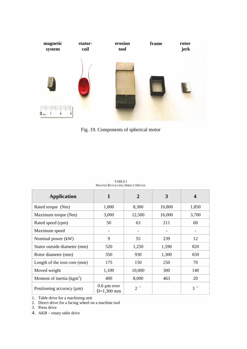
magnetic system
stator- coil
erosion tool
frame rotor jerk
Fig. 19. Components of spherical motor
TABLE I
PROVED REVOLVING DIRECT DRIVES
Application 1 2 3 4
Rated torque (Nm) 1,800 8,300 10,800 1,850
Maximum torque (Nm) 3,000 12,500 16,000 3,700
Rated speed (rpm) 50 63 211 60
Maximum speed - - - -
Nominal power (kW) 9 55 239 12
Stator outside diameter (mm) 520 1,250 1,590 820
Rotor diameter (mm) 350 930 1,300 650
Length of the iron core (mm) 175 150 250 70
Moved weight 1,100 10,000 300 140
Moment of inertia (kgm2) 400 8,000 463 20
Positioning accuracy (µm) 0.6 µm over D=1,300 mm 2 ´´ 3 ´´
1. Table drive for a machining unit 2. Direct drive for a facing wheel on a machine tool 3. Press drive 4. AKB – rotary table drive