SIMOTION SCOUT TIA Getting Started - University of Colorado...
142
SIMOTION Motion Control Getting Started with SIMOTION SCOUT TIA Getting Started Valid as of Version 4.5 11/2016 Preface Fundamental safety instructions 1 Getting Started with SIMOTION SCOUT TIA 2 Prepare the configuration 3 Create a project 4 Create SIMOTION device and configure online communication 5 Start SIMOTION SCOUT TIA 6 Download the project to the target system 7 Configure the drive 8 Configure the infeed 9 Configure the axis 10 Test the axis with the axis control panel 11 Configure digital outputs 12 Programming the SIMOTION application 13 Configure execution system 14 Starting and stopping the system 15 Monitor the application 16 ESD directives A Siemens Hardware
Transcript of SIMOTION SCOUT TIA Getting Started - University of Colorado...

SIMOTION
Motion ControlGetting Started with SIMOTION SCOUT TIA
Getting Started
Valid as of Version 4.5
11/2016
PrefaceFundamental safety instructions 1Getting Started with SIMOTION SCOUT TIA 2Prepare the configuration 3Create a project 4Create SIMOTION device and configure online communication
5
Start SIMOTION SCOUT TIA 6Download the project to the target system 7Configure the drive 8Configure the infeed 9Configure the axis 10Test the axis with the axis control panel 11Configure digital outputs 12Programming the SIMOTION application 13Configure execution system 14Starting and stopping the system 15Monitor the application 16ESD directives A
Siemens Hardware

Legal informationWarning notice system
This manual contains notices you have to observe in order to ensure your personal safety, as well as to prevent damage to property. The notices referring to your personal safety are highlighted in the manual by a safety alert symbol, notices referring only to property damage have no safety alert symbol. These notices shown below are graded according to the degree of danger.
DANGERindicates that death or severe personal injury will result if proper precautions are not taken.
WARNINGindicates that death or severe personal injury may result if proper precautions are not taken.
CAUTIONindicates that minor personal injury can result if proper precautions are not taken.
NOTICEindicates that property damage can result if proper precautions are not taken.If more than one degree of danger is present, the warning notice representing the highest degree of danger will be used. A notice warning of injury to persons with a safety alert symbol may also include a warning relating to property damage.
Qualified PersonnelThe product/system described in this documentation may be operated only by personnel qualified for the specific task in accordance with the relevant documentation, in particular its warning notices and safety instructions. Qualified personnel are those who, based on their training and experience, are capable of identifying risks and avoiding potential hazards when working with these products/systems.
Proper use of Siemens productsNote the following:
WARNINGSiemens products may only be used for the applications described in the catalog and in the relevant technical documentation. If products and components from other manufacturers are used, these must be recommended or approved by Siemens. Proper transport, storage, installation, assembly, commissioning, operation and maintenance are required to ensure that the products operate safely and without any problems. The permissible ambient conditions must be complied with. The information in the relevant documentation must be observed.
TrademarksAll names identified by ® are registered trademarks of Siemens AG. The remaining trademarks in this publication may be trademarks whose use by third parties for their own purposes could violate the rights of the owner.
Disclaimer of LiabilityWe have reviewed the contents of this publication to ensure consistency with the hardware and software described. Since variance cannot be precluded entirely, we cannot guarantee full consistency. However, the information in this publication is reviewed regularly and any necessary corrections are included in subsequent editions.
Siemens AGDivision Digital FactoryPostfach 48 4890026 NÜRNBERGGERMANY
Ⓟ 10/2016 Subject to changeCopyright © Siemens AG 2016.All rights reserved

Preface
Scope and standardsThis document is part of the Engineering System Handling documentation package.
Scope of validityThis manual is valid for SIMOTION SCOUT, product version V4.5.
SIMOTION DocumentationAn overview of the SIMOTION documentation can be found in the SIMOTION Documentation Overview document.
This documentation is included as electronic documentation in the scope of delivery of SIMOTION SCOUT TIA and it comprises ten documentation packages.
The following documentation packages are available for SIMOTION V4.5:
● SIMOTION Engineering System Handling
● SIMOTION System and Function Descriptions
● SIMOTION Service and Diagnostics
● SIMOTION IT
● SIMOTION Programming
● SIMOTION Programming - References
● SIMOTION C
● SIMOTION P
● SIMOTION D
● SIMOTION Supplementary Documentation
Hotline and Internet addresses
SIMOTION at a glanceWe have compiled an overview page from our range of information about SIMOTION with the most important information on frequently asked topics - which can be opened with only one click.
Whether beginner or experienced SIMOTION user – the most important downloads, manuals, tutorials, FAQs, application examples, etc. can be found at
https://support.industry.siemens.com/cs/ww/de/view/109480700
Getting Started with SIMOTION SCOUT TIAGetting Started, 11/2016 3
Siemens Hardware

Additional informationClick the following link to find information on the following topics:
● Documentation overview
● Additional links to download documents
● Using documentation online (find and search manuals/information)
https://support.industry.siemens.com/cs/ww/en/view/109479653
My Documentation ManagerClick the following link for information on how to compile documentation individually on the basis of Siemens content and how to adapt it for the purpose of your own machine documentation:
https://support.industry.siemens.com/My/ww/en/documentation
TrainingClick the following link for information on SITRAIN - Siemens training courses for automation products, systems and solutions:
http://www.siemens.com/sitrain
FAQsFrequently Asked Questions can be found in SIMOTION Utilities & Applications, which are included in the scope of delivery of SIMOTION SCOUT TIA, and in the Service&Support pages in Product Support:
https://support.industry.siemens.com/cs/de/en/ps/14505/faq
Technical supportCountry-specific telephone numbers for technical support are provided on the Internet under Contact:
https://support.industry.siemens.com/cs/ww/en/sc/2090
Preface
Getting Started with SIMOTION SCOUT TIA4 Getting Started, 11/2016

Table of contents
Preface.........................................................................................................................................................3
1 Fundamental safety instructions...................................................................................................................9
1.1 General safety instructions.......................................................................................................9
1.2 Industrial security...................................................................................................................10
1.3 Danger to life due to software manipulation when using removable storage media..............11
2 Getting Started with SIMOTION SCOUT TIA.............................................................................................13
2.1 Aim of Getting Started............................................................................................................13
2.2 Sample project.......................................................................................................................13
2.3 Requirements.........................................................................................................................14
2.4 General information................................................................................................................162.4.1 TIA Portal online help.............................................................................................................162.4.2 SIMOTION SCOUT TIA Online Help.....................................................................................162.4.3 Available documentation........................................................................................................172.4.4 Utilities & applications............................................................................................................182.4.5 Specific safety information.....................................................................................................19
3 Prepare the configuration...........................................................................................................................21
3.1 Restore factory settings.........................................................................................................21
3.2 Requirements for online communication................................................................................22
3.3 Result in the sample project...................................................................................................23
4 Create a project..........................................................................................................................................25
4.1 Overview................................................................................................................................25
4.2 Create new project.................................................................................................................25
4.3 Result in the sample project...................................................................................................26
5 Create SIMOTION device and configure online communication................................................................27
5.1 Overview................................................................................................................................27
5.2 Create SIMOTION device (1).................................................................................................28
5.3 Configure Ethernet interface (2).............................................................................................29
5.4 Set up PG/PC interface (3)....................................................................................................30
5.5 Result in the sample project...................................................................................................40
6 Start SIMOTION SCOUT TIA.....................................................................................................................41
7 Download the project to the target system.................................................................................................43
7.1 Overview................................................................................................................................43
7.2 Save and compile the project.................................................................................................43
Getting Started with SIMOTION SCOUT TIAGetting Started, 11/2016 5
Siemens Hardware

7.3 Connect to selected target devices – Go online.....................................................................44
7.4 Download the project to the target system.............................................................................48
8 Configure the drive.....................................................................................................................................51
8.1 Overview................................................................................................................................51
8.2 Automatic configuration of the drive.......................................................................................51
8.3 Result in the sample project...................................................................................................55
9 Configure the infeed...................................................................................................................................57
9.1 Overview................................................................................................................................57
9.2 Configuring an infeed without DRIVE‑CLiQ interface............................................................57
10 Configure the axis.......................................................................................................................................61
10.1 Overview................................................................................................................................61
10.2 Creating an axis.....................................................................................................................61
10.3 Download the axis configuration to the target system............................................................65
11 Test the axis with the axis control panel.....................................................................................................67
11.1 Overview................................................................................................................................67
11.2 Working with the axis control panel........................................................................................67
11.3 Result in the sample project...................................................................................................71
12 Configure digital outputs.............................................................................................................................73
13 Programming the SIMOTION application...................................................................................................75
13.1 Overview................................................................................................................................75
13.2 Variables................................................................................................................................7613.2.1 Variable types........................................................................................................................7613.2.2 Variables of the sample project..............................................................................................7613.2.3 Creating global device variables............................................................................................7713.2.4 Creating I/O variables............................................................................................................7813.2.5 Back up the configuration.......................................................................................................82
13.3 Programming..........................................................................................................................8213.3.1 Programming languages in the sample project......................................................................8213.3.2 MCC Motion Control Chart.....................................................................................................8213.3.2.1 The programming language MCC..........................................................................................8213.3.2.2 Creating the MCC unit............................................................................................................8313.3.2.3 Creating the MCC chart.........................................................................................................8413.3.2.4 Inserting command blocks into an MCC chart.......................................................................84
13.4 Creating an MCC sample program: basic framework............................................................8613.4.1 Overview................................................................................................................................8613.4.2 Program flow..........................................................................................................................8613.4.3 Variable assignment g_bo_ready:=false / g_bo_start:=true...................................................8713.4.4 Variable assignment g_bo_start:=true....................................................................................9013.4.5 Switch axis enable.................................................................................................................9213.4.6 Home axis..............................................................................................................................9313.4.7 Position the axis to the target position...................................................................................95
Table of contents
Getting Started with SIMOTION SCOUT TIA6 Getting Started, 11/2016
13.4.8 Position the axis to the starting position.................................................................................9713.4.9 Disable axis............................................................................................................................9913.4.10 Variable assignment g_bo_start:=false / g_bo_ready:=true.................................................10013.4.11 Variable assignment g_bo_ready:=true................................................................................100
13.5 Expanding the MCC sample program: control of the infeed................................................10013.5.1 Program flow........................................................................................................................10013.5.2 System function call _LineModule_control[FB].....................................................................10213.5.3 Variable assignment LineModule_STW:=myFB_LineControl.periOut..................................10513.5.4 Create UNTIL loop...............................................................................................................10613.5.5 Copy blocks..........................................................................................................................10713.5.6 Adapt the system function call _linemodule_control.............................................................108
13.6 Create additional MCC programs for the sample project.....................................................108
13.7 Back up MCC sample programs..........................................................................................109
13.8 LAD/FBD ladder logic/function block diagram......................................................................11013.8.1 The LAD and FBD programming languages........................................................................11013.8.2 Create LAD/FBD unit...........................................................................................................11113.8.3 Create LAD/FBD program....................................................................................................11113.8.4 Creating a LAD sample program..........................................................................................11313.8.5 Back up LAD/FBD sample program.....................................................................................116
13.9 Further programming options...............................................................................................117
13.10 Result in the sample project.................................................................................................117
14 Configure execution system.....................................................................................................................119
14.1 Overview..............................................................................................................................119
14.2 Assign programs to tasks.....................................................................................................119
14.3 Download the configured execution system to the target system........................................122
14.4 Result in the sample project.................................................................................................123
15 Starting and stopping the system.............................................................................................................125
15.1 Overview..............................................................................................................................125
15.2 RUN and STOP operating modes........................................................................................125
15.3 Mode selector switch on the software side and the hardware side......................................126
15.4 Start program control of the sample project.........................................................................127
16 Monitor the application.............................................................................................................................129
16.1 Overview..............................................................................................................................129
16.2 Monitoring program execution..............................................................................................129
16.3 Monitoring variables.............................................................................................................131
16.4 Recording signals with the trace..........................................................................................13216.4.1 Trace....................................................................................................................................13216.4.2 Working with the trace..........................................................................................................133
16.5 Result in the sample project.................................................................................................137
Table of contents
Getting Started with SIMOTION SCOUT TIAGetting Started, 11/2016 7
Siemens Hardware

A ESD directives..........................................................................................................................................139
A.1 ESD definition......................................................................................................................139
A.2 Electrostatic charging of individuals.....................................................................................139
A.3 Basic measures for protection against discharge of static electricity...................................140
Index.........................................................................................................................................................141
Table of contents
Getting Started with SIMOTION SCOUT TIA8 Getting Started, 11/2016

Fundamental safety instructions 11.1 General safety instructions
WARNING
Danger to life if the safety instructions and residual risks are not observed
The non-observance of the safety instructions and residual risks stated in the associated hardware documentation can result in accidents with severe injuries or death.● Observe the safety instructions given in the hardware documentation.● Consider the residual risks for the risk evaluation.
WARNING
Danger to life caused by machine malfunctions caused by incorrect or changed parameterization
Incorrect or changed parameterization can cause malfunctions on machines that can result in injuries or death.● Protect the parameterization (parameter assignments) against unauthorized access.● Respond to possible malfunctions by applying suitable measures (e.g. EMERGENCY
STOP or EMERGENCY OFF).
Getting Started with SIMOTION SCOUT TIAGetting Started, 11/2016 9
Siemens Hardware

1.2 Industrial security
NoteIndustrial security
Siemens provides products and solutions with industrial security functions that support the secure operation of plants, systems, machines and networks.
In order to protect plants, systems, machines and networks against cyber threats, it is necessary to implement – and continuously maintain – a holistic, state-of-the-art industrial security concept. Siemens’ products and solutions only form one element of such a concept.
Customer is responsible to prevent unauthorized access to its plants, systems, machines and networks. Systems, machines and components should only be connected to the enterprise network or the internet if and to the extent necessary and with appropriate security measures (e.g. use of firewalls and network segmentation) in place.
Additionally, Siemens’ guidance on appropriate security measures should be taken into account. For more information about industrial security, please visit http://www.siemens.com/industrialsecurity.
Siemens’ products and solutions undergo continuous development to make them more secure. Siemens strongly recommends to apply product updates as soon as available and to always use the latest product versions. Use of product versions that are no longer supported, and failure to apply latest updates may increase customer’s exposure to cyber threats.
To stay informed about product updates, subscribe to the Siemens Industrial Security RSS Feed under http://www.siemens.com/industrialsecurity..
WARNING
Danger as a result of unsafe operating states resulting from software manipulation
Software manipulation (e.g. by viruses, Trojan horses, malware, worms) can cause unsafe operating states to develop in your installation which can lead to death, severe injuries and/or material damage.● Keep the software up to date.
Information and newsletters can be found at: http://support.automation.siemens.com
● Incorporate the automation and drive components into a state-of-the-art, integrated industrial security concept for the installation or machine.For more detailed information, go to: http://www.siemens.com/industrialsecurity
● Make sure that you include all installed products into the integrated industrial security concept.
Fundamental safety instructions1.2 Industrial security
Getting Started with SIMOTION SCOUT TIA10 Getting Started, 11/2016

1.3 Danger to life due to software manipulation when using removable storage media
WARNING
Danger to life due to software manipulation when using removable storage media
The storage of files on removable storage media involves a high risk of infection, e.g. via viruses or malware. Incorrect parameter assignment can cause machines to malfunction, which can lead to injuries or death.● Protect the files on removable storage media against harmful software through appropriate
protective measures, e.g. virus scanners.
Fundamental safety instructions1.3 Danger to life due to software manipulation when using removable storage media
Getting Started with SIMOTION SCOUT TIAGetting Started, 11/2016 11
Siemens Hardware

Fundamental safety instructions1.3 Danger to life due to software manipulation when using removable storage media
Getting Started with SIMOTION SCOUT TIA12 Getting Started, 11/2016

Getting Started with SIMOTION SCOUT TIA 22.1 Aim of Getting Started
Getting Started introduces you to working with the SIMOTION SCOUT TIA engineering system. You will create a simple sample project and in so doing, you will work through the typical steps involved in configuring devices, drives, and axes. You will become familiar with the most important tools that SIMOTION SCOUT TIA provides for configuring, programming, and diagnostics.
2.2 Sample projectGetting Started provides you with instructions for creating a simple sample project.
Configuring steps
Prepare the configuration● You reset the SIMOTION device to the factory settings.
● You configure the interface for network communication between the PG/PC and the SIMOTION device.
Create project, configure SIMOTION device and network communication with the PG/PC● You create a project.
● You create a SIMOTION device and set up the network communication between the PG/PC and the SIMOTION device .
Configure the drive● You commission the drive.
Configure the infeed● You interconnect the infeed with the drive.
Configure and test the axis● You set up an axis.
● You interconnect the axis with the drive.
● You test the axis with the axis control panel.
Configure inputs/outputs● You configure I/Os for use in the sample program.
Getting Started with SIMOTION SCOUT TIAGetting Started, 11/2016 13
Siemens Hardware

Program, set up and monitor SIMOTION● You write a simple SIMOTION user program that controls the configured axis.
– You create the variables required by the program.
– You create the program and additional auxiliary programs with the graphical editors.
● You assign the finished programs to the tasks of the execution system.
● You start program execution in the SIMOTION runtime system.
● You monitor the program-controlled axis movement.
– You monitor program execution.
– You monitor the values in the symbol browser.
– You compile values in a watch table.
– You record the course of the axis motion with the trace.
2.3 RequirementsGetting Started provides you with instructions for creating a simple sample project.
Trainings systemTo create the sample project, you require a training system with a few components:
● SIMOTION D4x5-2 device with the latest firmware V4.5
● PG/PC with free Ethernet interfaceA USB Ethernet adapter is also suitable for the Ethernet connection.
Note
A USB PROFIBUS adapter, e.g. PC Adapter USB A2 (article number: 6GK1571-0BA00-0AA0) can be used for the PROFIBUS connection. Performance problems may occur if a previous version is used.
● Full DRIVE‑CLiQ wiring of the components; motor with DRIVE‑CLiQ interface and thus with automatic encoder identification (SMI Sensor Module Integrated)
● TIA Portal and SIMOTION SCOUT TIA engineering system
A SIMOTION D435-2 DP/PN device is used in the sample project.
The PROFINET interface of the SIMOTION device is not used in the sample project.
Note
Getting Started deals with automatic drive configuration and not configuration using the drive wizard. To be able to carry out automatic drive configuration fully, full DRIVE‑CLiQ wiring of the components involved is a necessary requirement.
Getting Started with SIMOTION SCOUT TIA2.3 Requirements
Getting Started with SIMOTION SCOUT TIA14 Getting Started, 11/2016

Preparation of the training systemYour training system has been prepared for configuring with TIA Portal and SIMOTION SCOUT TIA:
● The hardware is ready installed and wired.
● The CF card with the latest firmware V4.5 is plugged in.
● The PG/PC and SIMOTION D435-2 are connected direct via Ethernet cable. The Ethernet X127 interface on the SIMOTION D435‑2 is used for the connection.
● TIA Portal (V14 or higher) is installed on the PG/PC.
● SIMOTION SCOUT TIA (at least V4.5) is installed on the PG/PC and licensed correctly.
● You have started the TIA Portal. The portal view is visible on the screen of the PG/PC.
Overview of configuring steps The table below provides an overview of the individual configuring steps and where you implement them.
Configuring step Where Chapter① Create project TIA Portal see Creating project (Page 25)② Create the SIMOTION device and configure online communication (incl. compilation of the hardware configuration and downloading to the SIMOTION device)
TIA Portal see Creating the SIMOTION device and configuring online communica‐tion (Page 27)
③ Start SIMOTION SCOUT TIA TIA Portal see Starting SIMOTION SCOUT TIA (Page 41)
④ Download the project to the target system (incl. compilation)
SIMOTION SCOUT TIA see Downloading the project to the target system (Page 43)
⑤ Configure the drive SIMOTION SCOUT TIA see Configuring the drive (Page 51)⑥ Configure the infeed SIMOTION SCOUT TIA see Configuring the infeed
(Page 57)⑦ Configuration of technology objects (in the TO Axis example)
SIMOTION SCOUT TIA see Configuring axis (Page 61) / Testing the axis using the axis con‐trol panel (Page 67)
⑧ Configure digital outputs SIMOTION SCOUT TIA see Configuring digital outputs (Page 73)
⑨ Creation of user programs SIMOTION SCOUT TIA see Programming the SIMOTION application (Page 75)
⑩ Configuring the execution system SIMOTION SCOUT TIA see Configuring the execution sys‐tem (Page 119)
⑪ Starting and stopping the system SIMOTION SCOUT TIA see Starting and stopping the sys‐tem (Page 125)
⑫ Monitor the application SIMOTION SCOUT TIA see Monitoring the application (Page 129)
Getting Started with SIMOTION SCOUT TIA2.3 Requirements
Getting Started with SIMOTION SCOUT TIAGetting Started, 11/2016 15
Siemens Hardware

2.4 General information
2.4.1 TIA Portal online helpThe TIA Portal has an extensive online help system.
How to open the online help● Select Help > Show help in the menu, or
● press the F1 key.
After calling the online help, you will be in the information system. What help is available to you and how you can operate the help in the TIA Portal is explained in Further support > Help on the information system.
2.4.2 SIMOTION SCOUT TIA Online HelpSIMOTION SCOUT TIA has a comprehensive online help. You can optionally search for specific topics in the online help or call the help from the context of your work.
How to open the online help● Select Help > Help topics in the menu, or
● press the F1 key.
How to open the context-sensitive online help● Click the Help button of the dialog or window, or
● press the key combination Shift+F1, or
● click in the toolbar on the Help button.
With the mouse pointer (changed to a question mark), click the parameter or the window for which you require help.
You can find detailed information on using the context-sensitive help in the online help under SIMOTION SCOUT TIA > General > Use Help.
Getting Started with SIMOTION SCOUT TIA2.4 General information
Getting Started with SIMOTION SCOUT TIA16 Getting Started, 11/2016

Full text search in the online helpYou can find important information on full text searching in the online help under Basic > Use Online Help and Function Block Diagrams > Use Online Help > Full Text Search.
NoteFull text search in the online help
Enclose the search term between asterisks * to include search results that contain the search term as part of a longer character string, e.g. ● variable finds only the whole words "variable" or "Variable",● *variable* also finds "system variables", "variable assignment", etc.
2.4.3 Available documentation
Electronic documentationThe documentation is included in electronic form in the scope of delivery of SIMOTION SCOUT TIA (SIMOTION SCOUT DVD Documentation, Utilities & Applications). You can search for all PDF documents in the electronic documentation with an index (SIMOTION.pdx). You can find an overview of the structure and content of the SIMOTION PDF documentation in the separate document Overview of the SIMOTION Documentation.
The content of the documents is also available in the SIMOTION SCOUT TIA online help, with a few exceptions.
In the online help, you can find the Overview of the SIMOTION Documentation under Overview of the SIMOTION Documentation > … > Overview of the SIMOTION Documentation.
Note
You will find the SIMOTION SCOUT TIA Configuration Manual as a PDF document on the SIMOTION SCOUT DVD.
Overview of SIMOTIONYou can find a brief system overview of SIMOTION in the online help under Basic > Basic Functions > System Overview.
The manuals contain comprehensive information especially for configuring and commissioning a SIMOTION D, see the SIMOTION D4x5-2 Manual as well as the SIMOTION D4x5-2 Commissioning and Hardware Installation Manual. You can also find the SIMOTION D manuals in the online help under SIMOTION Devices > SIMOTION D.
Getting Started with SIMOTION SCOUT TIA2.4 General information
Getting Started with SIMOTION SCOUT TIAGetting Started, 11/2016 17
Siemens Hardware

Additional informationYou will find additional information and documents on SIMOTION in the Industry Online Support. Here, you are provided with an overview of the most important technical information and solutions for SIMOTION.
http://support.automation.siemens.com/WW/view/de/10805436/130000
You can also access the Online Support via the hardware catalog of the TIA Portal (select the relevant modules and open the shortcut menu).
2.4.4 Utilities & applicationsThe free SIMOTION Utilities & Applications provide you with a wealth of important background information on all aspects of SIMOTION, tools, special functions, blocks, SIMOTION sample projects, as well as off-the-shelf standard applications for illustration or for use in your projects. There you can also find detailed information on scripting and a host of sample scripts that facilitate working with SIMOTION.
1. FAQsInteresting FAQs such as control of hydraulic axes or communication issues.
2. ScriptsA host of scripts, helpful tips, but also extensive solutions that make recurring tasks easier, for example.
Note
As part of SIMOTION SCOUT TIA (TIA Portal), only scripts can be used that influence or use pure SIMOTION SCOUT/SIMOTION SCOUT TIA data and functionalities.
Scripting of the data/functionalities of the HWCN and the project handling of the TIA Portals (framework) is not possible.
The following is explicitly impossible by scripting:● Creation, deletion, and renaming of objects that have a representation in the TIA Portal
(for example, all SIMOTION devices).● Creation, deletion, and renaming of projects.● File system accesses to TIA Portal projects.● Use of functionalities that are provided by the TIA Portal (framework), e.g.● Archiving/dearchiving.● All handling of TIA Portal data.
The project generator SIMOTION easyProject cannot be used for projects with SIMOTION SCOUT TIA because the scripting functionality is not yet available in the TIA Portal.
Also note that external scripting is not supported by SIMOTION SCOUT TIA.
3. Tools and documentationYou are provided with easy-to-use tools and in-depth documentation for many tasks.
4. ExamplesSample projects for first-time-users, e.g. "Getting Started", as well as examples of special topics.
Getting Started with SIMOTION SCOUT TIA2.4 General information
Getting Started with SIMOTION SCOUT TIA18 Getting Started, 11/2016

5. ApplicationsFor SIMOTION, there is a host of applications available to you that provide you with a sound basic framework. With the aid of the supplied documentation, you can use the applications as a basis for your own application, and adapt and expand them.Furthermore, functions are available to you under "Cross-Sector applications" that are of general help when creating your own applications, e.g. a LDPV1 library for drive communication via DPV1 services (read and write SINAMICS parameters, read errors and warnings from SINAMICS, deactivate objects, ramp-up coordination and much more), or the LCom library with functions for communication with TCP/IP for SIMOTION and SIMATIC.
6. SIMOTION ITUnder SIMOTION IT, you can find innovative examples and tools for bringing control and drive solutions a little closer to the IT world. These include a trace function that is executed via an Internet browser, as well as examples for user-defined Web pages for the SIMOTION IT Web server or for using OPC XML DA.
2.4.5 Specific safety informationMake sure your training system is fully disconnected from productive operation.
Observe the safety notes in the documentation of the devices used.
Getting Started with SIMOTION SCOUT TIA2.4 General information
Getting Started with SIMOTION SCOUT TIAGetting Started, 11/2016 19
Siemens Hardware

Getting Started with SIMOTION SCOUT TIA2.4 General information
Getting Started with SIMOTION SCOUT TIA20 Getting Started, 11/2016

Prepare the configuration 33.1 Restore factory settings
For the sample project, it is useful to reset the SIMOTION device to the factory settings.
In this way, you restore the default communications parameters and you delete user data installed on the device and the CF card by a previous configuration. The runtime licenses are retained.
You restore the factory settings on the SIMOTION device as follows1. Switch off the power supply of the SIMOTION device.
2. Set the mode selector switch ③ of the SIMOTION device to position 3.
① LED display② 7-segment display③ Mode selector switch in position 3
Figure 3-1 SIMOTION D435‑2 module front
NOTICE
Damage from electrostatic discharge
The rotary switch can be destroyed by static electricity.
Operate the rotary switch only with an insulated screwdriver.
Observe the ESD regulations.
Getting Started with SIMOTION SCOUT TIAGetting Started, 11/2016 21
Siemens Hardware

3. Switch on the power supply of the SIMOTION device.The default settings are loaded. SIMOTION D435‑2 switches to STOP mode.Wait for the procedure to finish. The elements on the front of the module indicate completion:
– The 7-segment display ② shows status digit 6: SIMOTION D435-2 has started up.
– LEDs ①:LED RDY flashes green (0.5 Hz): the drive is ready for commissioning.LED STOP shows a yellow light: the SIMOTION device is in STOP mode.All other LEDs are off.
4. Turn the mode selector switch ③ to position 0.
– The LED RUN shows a green light: the SIMOTION device is in RUN mode.
ResultThe SIMOTION device has been restored to its factory settings and is ready for commissioning.
3.2 Requirements for online communicationOnline communication of the PG/PC with the SIMOTION device can be set up via PROFIBUS, PROFINET, or Industrial Ethernet. The sample project is restricted to the most frequent application case: communication via Industrial Ethernet.
Prepare the configuration3.2 Requirements for online communication
Getting Started with SIMOTION SCOUT TIA22 Getting Started, 11/2016

Requirements● The PG/PC and the SIMOTION device are connected via an Ethernet cable.
● The X127 PN/IE interface on the SIMOTION device is used for the Ethernet connection.
① Ethernet interface X127 PN/IE
Figure 3-2 SIMOTION D435‑2 module front
● The Ethernet interface X127 PN/IE has the default address:IP address: 169.254.11.22 - Subnet: 255.255.0.0
See alsoConfigure Ethernet interface (2) (Page 29)
3.3 Result in the sample projectThe factory settings of the SIMOTION device have been restored. The requirements for online communication of the PG/PC with the SIMOTION device are fulfilled.
Prepare the configuration3.3 Result in the sample project
Getting Started with SIMOTION SCOUT TIAGetting Started, 11/2016 23
Siemens Hardware

Prepare the configuration3.3 Result in the sample project
Getting Started with SIMOTION SCOUT TIA24 Getting Started, 11/2016

Create a project 44.1 Overview
Aim of Getting StartedIn this part of Getting Started, you create the sample project Sample_1 in the TIA Portal. All of the subsequent configuring steps refer to this sample project.
ProjectA project contains all the information that describes a machine and its function: configuration data, programs, motion profiles, drive data.
A project can contain several SIMOTION devices.
4.2 Create new projectAfter opening the TIA Portal, you are in the portal view. The portal view offers a task-oriented view of the tools, and provides the basic functions for the individual task areas.
You create a new project as followsYou start a new configuration by creating a new project in the TIA Portal.
1. Select Start > Create new project in the navigation of the portal view. The Create new project dialog appears.
Figure 4-1 Create a project
2. Enter the project name under Project name, e.g. Sample_1.
Getting Started with SIMOTION SCOUT TIAGetting Started, 11/2016 25
Siemens Hardware
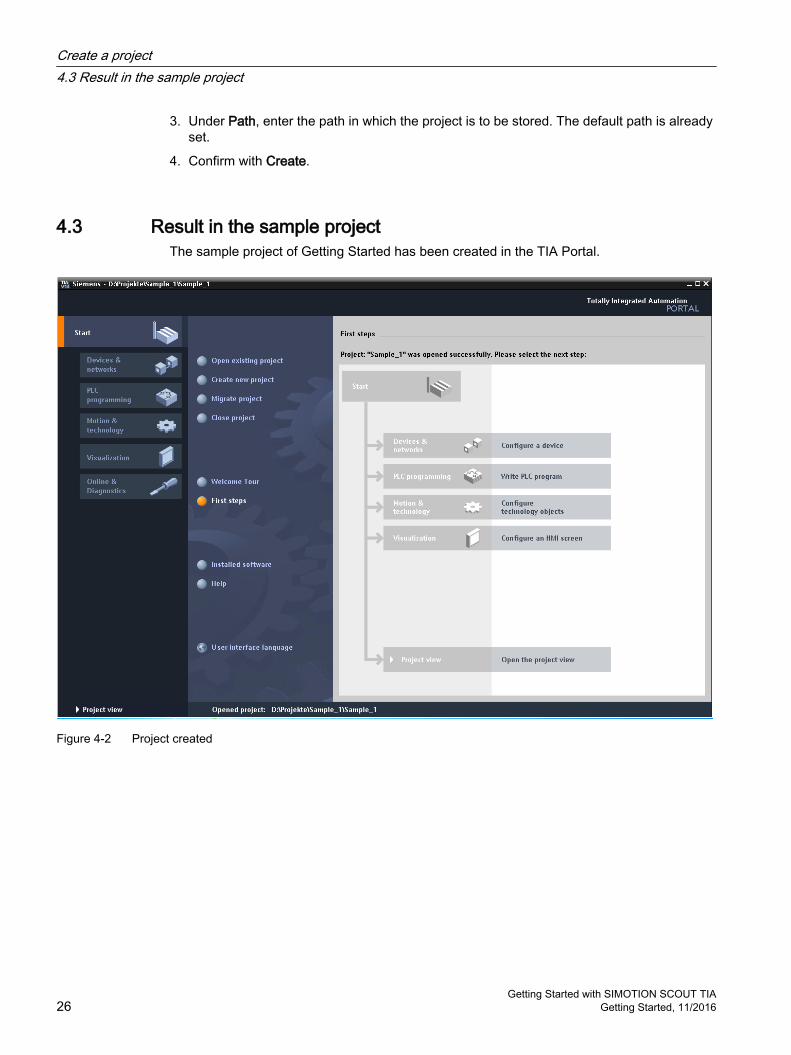
3. Under Path, enter the path in which the project is to be stored. The default path is already set.
4. Confirm with Create.
4.3 Result in the sample projectThe sample project of Getting Started has been created in the TIA Portal.
Figure 4-2 Project created
Create a project4.3 Result in the sample project
Getting Started with SIMOTION SCOUT TIA26 Getting Started, 11/2016

Create SIMOTION device and configure online communication 55.1 Overview
Aim of Getting StartedThis part of Getting Started shows you how to create a SIMOTION device in the project in the TIA Portal and how to set up communication between the PG/PC and the SIMOTION device.
StepsThe following steps are executed in order to create a SIMOTION device in the project:
1. Create a SIMOTION device.
2. Configure the Ethernet interface.
3. Set up communication between PG/PC and SIMOTION device, compile the project, and download to the device.
SIMOTION D platformSIMOTION D is the drive-based version of the SIMOTION motion control system, based on the SINAMICS S120 family of drives. With SIMOTION D, the SIMOTION motion control functionalities and the SINAMICS drive software run on a SINAMICS-type closed-loop control hardware device. SIMOTION D devices have the following characteristic features:
● Motion control functionality and control functionality integrated directly in the drive
● Compact and with especially fast response
● Maximum scalability and flexibility as single-axis or multi-axis system in different performance versions for diverse applications
● Especially suitable for modular machine concepts with fast isochronous coupling, in the case of machines with a large number of axes, for example
The SINAMICS functionality of the closed-loop-control module of the SINAMICS S120 multi-axis drive system is integrated in SIMOTION D (SINAMICS Integrated).
You will find a brief introduction to SIMOTION D in the online help using the example of the D435 Control Unit. Click Help > Tutorials > SIMOTION Drive‑Based in the SIMOTION SCOUT menu bar.
Getting Started with SIMOTION SCOUT TIAGetting Started, 11/2016 27
Siemens Hardware
5.2 Create SIMOTION device (1)
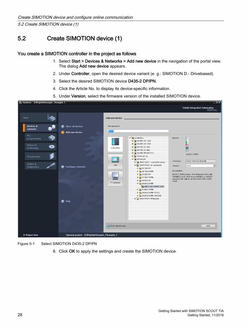
You create a SIMOTION controller in the project as follows1. Select Start > Devices & Networks > Add new device in the navigation of the portal view.
The dialog Add new device appears.
2. Under Controller, open the desired device variant (e. g.: SIMOTION D - Drivebased).
3. Select the desired SIMOTION device D435-2 DP/PN.
4. Click the Article No. to display its device-specific information.
5. Under Version, select the firmware version of the installed SIMOTION device.
Figure 5-1 Select SIMOTION D435-2 DP/PN
6. Click OK to apply the settings and create the SIMOTION device.
Create SIMOTION device and configure online communication5.2 Create SIMOTION device (1)
Getting Started with SIMOTION SCOUT TIA28 Getting Started, 11/2016

ResultThe SIMOTION device is created in the project. After you have created the device, you will be in the project view on the Device View tab.
Figure 5-2 SIMOTION D435-2 DP/PN in the device view
Note
The selected firmware version must match the firmware version on the memory card of the device. Otherwise an error message will appear as soon as you switch to online mode.
5.3 Configure Ethernet interface (2)You can set up online communication of the PG/PC with the SIMOTION device via PROFIBUS, PROFINET, or Industrial Ethernet.
The most common use case is communication via Industrial Ethernet (communication via PROFINET protocol).
It is necessary to create a subnet if you are configuring IO devices. The following example shows how a subnet is created.
Create SIMOTION device and configure online communication5.3 Configure Ethernet interface (2)
Getting Started with SIMOTION SCOUT TIAGetting Started, 11/2016 29
Siemens Hardware

ProcedureProceed as follows to create a subnet:
1. To do so, first switch to the network view in the project view.
2. Click with the mouse on the Ethernet interface X127 of the SIMOTION device on which you want tocreate a subnet.
3. Right-click to select Add Subnet from the shortcut menu.
Figure 5-3 Adding a subnet
ResultThe Ethernet subnet is shown in the network view.
Figure 5-4 Ethernet subnet in the network view
5.4 Set up PG/PC interface (3)
Note
You assign the PG/PC interface in the TIA Portal.
Create SIMOTION device and configure online communication5.4 Set up PG/PC interface (3)
Getting Started with SIMOTION SCOUT TIA30 Getting Started, 11/2016

Communication between a SIMOTION device and a PG/PC requires a conditioner card (for PROFIBUS) or an Ethernet interface. You configure, parameterize, program and test using the PG/PC.
You have the following functions to assign the PG/PC interface:
● Connect online function The function is available until the PG/PC interface has been successfully set up.
● Online & diagnostics function
● Online access function
Assign PG/PC interface
The following procedure describes the process for the Ethernet interface type by using the "Online access" function.
Create SIMOTION device and configure online communication5.4 Set up PG/PC interface (3)
Getting Started with SIMOTION SCOUT TIAGetting Started, 11/2016 31
Siemens Hardware

To assign the interfaces, proceed as follows:
1. Navigate to the relevant interface in the project navigation under Online access.
2. In the shortcut menu, click Properties.
Figure 5-5 Online access properties
3. In the next step, select the subnet and apply the setting with OK.
Create SIMOTION device and configure online communication5.4 Set up PG/PC interface (3)
Getting Started with SIMOTION SCOUT TIA32 Getting Started, 11/2016

Figure 5-6 Assigning a subnet
Adding an IP address in the subnetIf the SIMOTION device and the PG/PC are not in the same subnet, add a suitable IP address from the subnet of the device to the PG/PC.
Create SIMOTION device and configure online communication5.4 Set up PG/PC interface (3)
Getting Started with SIMOTION SCOUT TIAGetting Started, 11/2016 33
Siemens Hardware

To automatically add an IP address in the subnet, proceed as follows:
1. Click in the toolbar.The Connect online dialog opens.
Figure 5-7 Selecting a device for online connection
2. Click Connect to establish a connection to the device located by the search.
Create SIMOTION device and configure online communication5.4 Set up PG/PC interface (3)
Getting Started with SIMOTION SCOUT TIA34 Getting Started, 11/2016

3. If the SIMOTION device and the PG/PC are not in the same subnet, a message is displayed offering you the option of temporarily assigning a suitable IP address from the subnet of the device.
Figure 5-8 Assigning an IP address
4. Click Yes to confirm.
Figure 5-9 IP address assigned
Result● You have assigned the PG/PC interface.
● The TIA Portal has assigned an IP address internally within the project.
● The online connection has been established.The title bar of the project navigation is now orange.
Create SIMOTION device and configure online communication5.4 Set up PG/PC interface (3)
Getting Started with SIMOTION SCOUT TIAGetting Started, 11/2016 35
Siemens Hardware
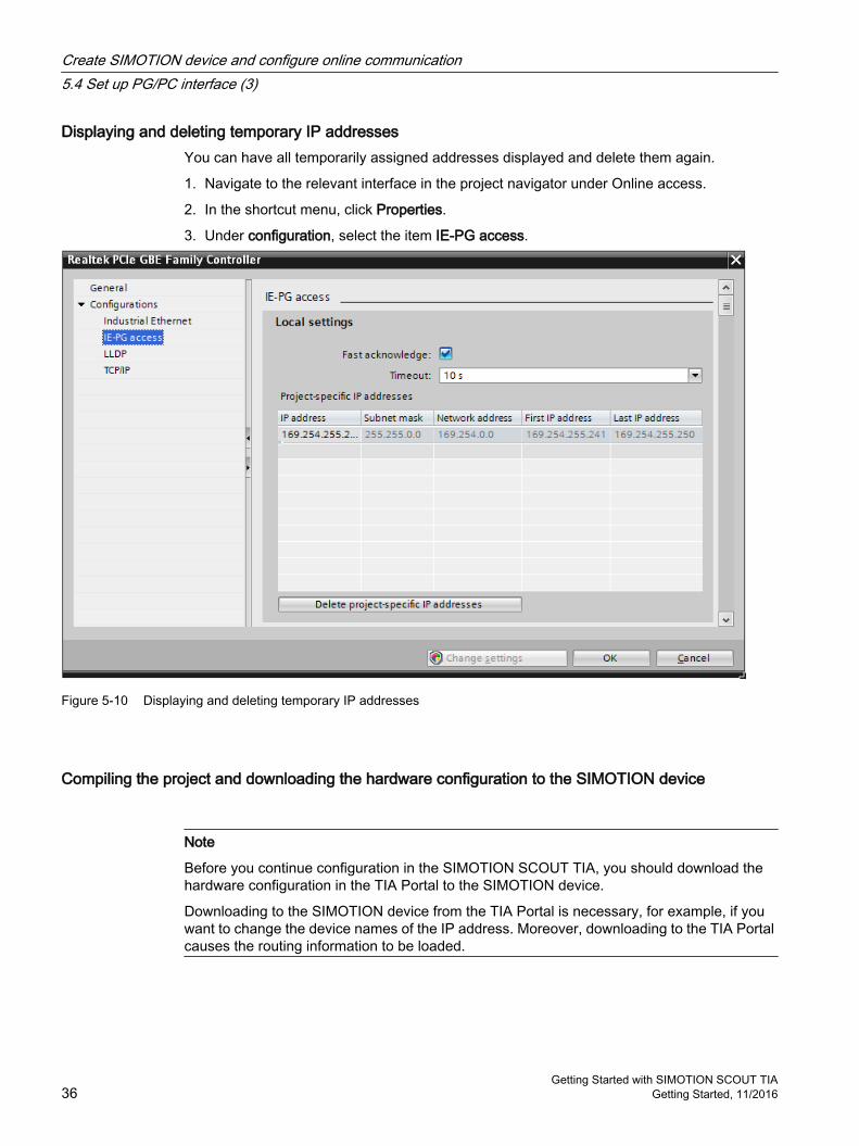
Displaying and deleting temporary IP addressesYou can have all temporarily assigned addresses displayed and delete them again.
1. Navigate to the relevant interface in the project navigator under Online access.
2. In the shortcut menu, click Properties.
3. Under configuration, select the item IE-PG access.
Figure 5-10 Displaying and deleting temporary IP addresses
Compiling the project and downloading the hardware configuration to the SIMOTION device
Note
Before you continue configuration in the SIMOTION SCOUT TIA, you should download the hardware configuration in the TIA Portal to the SIMOTION device.
Downloading to the SIMOTION device from the TIA Portal is necessary, for example, if you want to change the device names of the IP address. Moreover, downloading to the TIA Portal causes the routing information to be loaded.
Create SIMOTION device and configure online communication5.4 Set up PG/PC interface (3)
Getting Started with SIMOTION SCOUT TIA36 Getting Started, 11/2016

RequirementThe online connection with the SIMOTION device is disconnected.
Create SIMOTION device and configure online communication5.4 Set up PG/PC interface (3)
Getting Started with SIMOTION SCOUT TIAGetting Started, 11/2016 37
Siemens Hardware

ProcedureTo compile the hardware configuration and download to the SIMOTION device, proceed as follows:
1. Select the SIMOTION device and select via the shortcut menu Compile > Hardware (changes only).
Figure 5-11 Compiling hardware
2. Select the SIMOTION device and select via the shortcut menu Download to device > Hardware configuration.
Create SIMOTION device and configure online communication5.4 Set up PG/PC interface (3)
Getting Started with SIMOTION SCOUT TIA38 Getting Started, 11/2016

Figure 5-12 Loading hardware
ResultYou have compiled the current hardware configuration and loaded it to the target device.
Additional referencesFor detailed information about the configuration of the online access, refer to the information system of the TIA Portal "Configuring online access".
Create SIMOTION device and configure online communication5.4 Set up PG/PC interface (3)
Getting Started with SIMOTION SCOUT TIAGetting Started, 11/2016 39
Siemens Hardware

5.5 Result in the sample project
Newly created SIMOTION deviceConfiguring of the SIMOTION device and network communication between the PG/PC and the SIMOTION device is complete.
● The newly created SIMOTION D435‑2 device is shown in the project tree of the Project view.
● The PG/PC is connected with the SIMOTION device via Ethernet.
● The project is compiled and the hardware configuration is loaded into the SIMOTION device.
No other hardware configuration is required for the sample project.
Create SIMOTION device and configure online communication5.5 Result in the sample project
Getting Started with SIMOTION SCOUT TIA40 Getting Started, 11/2016

Start SIMOTION SCOUT TIA 6Note
You can only start SIMOTION SCOUT TIA from the TIA Portal.
After you have created the project in the TIA Portal and you have configured the hardware and communication, start SIMOTION SCOUT TIA to configure the technology.
ProcedureYou can start SIMOTION SCOUT TIA in the following ways:
In the portal view1. Click the "Motion & Technology" function.
2. Click the "Open SIMOTION configuration" entry in the secondary navigation.
In the project view1. Start SIMOTION SCOUT TIA via the "Project > Open SIMOTION configuration" menu.
Or double-click the "SIMOTION configuration" menu entry below the SIMOTION device in the project tree.
NoteDisconnecting the online connection to the TIA Portal
You should not go online simultaneously in the TIA Portal and SIMOTION SCOUT TIA.
Always disconnect the online connection in the TIA Portal before going online with SIMOTION SCOUT TIA. You need to do this so that programs can be compiled in SIMOTION SCOUT TIA.
Making basic settings In SIMOTION SCOUT TIA, you can make various basic settings via the "Options > Settings..." menu.
To make the settings, proceed as follows:
1. In the "Options" menu, select the "Settings..." command.The "Settings" dialog opens.
2. Switch to the desired tab.
3. Make the settings.
4. Confirm with "OK".
Getting Started with SIMOTION SCOUT TIAGetting Started, 11/2016 41
Siemens Hardware

Additional referencesYou will find detailed information on the individual tabs and settings in the SIMOTION SCOUT TIA Online Help.
Start SIMOTION SCOUT TIA
Getting Started with SIMOTION SCOUT TIA42 Getting Started, 11/2016

Download the project to the target system 77.1 Overview
Aim of Getting StartedIn this configuring step, you create the prerequisites for configuring the drive.
● You back up the created sample project to the hard disk.
● You compile the project into executable code.
● You establish online communication with the SIMOTION device.
● You download the project from the PG/PC to the SIMOTION device.
7.2 Save and compile the projectTo be able to download a project created in SIMOTION SCOUT TIA to the target system, the project must be saved in executable code.
The command Save project and compile changes combines both steps. The project is backed up to the hard disk. SIMOTION SCOUT TIA searches the entire project for changes and compiles only the changes.
Note
Use the command Save project and compile changes for preference for day-to-day work.
Several variations of the "Save" command are available for selection under the menu title Project. You can find information on this in the online help under Save and compile.
You save and compile a project as followsSelect the menu command Project > Save and compile changes or click the relevant button in the toolbar.
The compilation run is logged in the detail view of the workbench. Information, warning and compilation errors are shown there in plain text.
Switch on detail viewThe detail view might be switched off. Click the menu item View > Detail view to activate the view.
Getting Started with SIMOTION SCOUT TIAGetting Started, 11/2016 43
Siemens Hardware

7.3 Connect to selected target devices – Go onlineTo download project data from SIMOTION SCOUT TIA to the hardware, or to transfer machine data in the other direction from the hardware to the SIMOTION SCOUT TIA project, communication between the PG/PC and the SIMOTION device must be activated.
The status of the network communication is displayed in the footer of the workbench:
Network communication is switched on. Data can be exchanged.The network connection is switched off.
Download the project to the target system7.3 Connect to selected target devices – Go online
Getting Started with SIMOTION SCOUT TIA44 Getting Started, 11/2016

You go online as follows1. Select the menu command Project > Connect with selected target devices or click the
relevant button in the toolbar.
When the command is first called, SIMOTION SCOUT TIA opens the Target Device Selection dialog box. The dialog enables individual selection of the devices to which SIMOTION SCOUT TIA is to connect.
Note
For fast working with SCOUT TIA, we recommend only selecting devices that are currently needed (e.g. deselection of the SINAMICS drives if drive commissioning has been completed).
You will find the setting in the menu under Target system > Select target devices.... Selection and deselection of the device online can also be
performed via the shortcut menu Connect to target device on the device.
2. In the dialog box, select the configured SIMOTION device PLC_1 and the integrated drive SINAMICS_Integrated_1.
Download the project to the target system7.3 Connect to selected target devices – Go online
Getting Started with SIMOTION SCOUT TIAGetting Started, 11/2016 45
Siemens Hardware

Figure 7-1 Target Device Selection dialog
Note
The properties of the access point S7ONLINE are defined in the TIA Portal. With this access point, you go online via the interface that you have configured in the TIA Portal.
The DEVICE (STARTER) access point provides the option of connecting SIMOTION SCOUT TIA either in parallel or alternatively to S7ONLINE, directly to a device, e.g. via the Ethernet interface. The properties configured in SIMOTION SCOUT TIA are only applied for the DEVICE access point.
Download the project to the target system7.3 Connect to selected target devices – Go online
Getting Started with SIMOTION SCOUT TIA46 Getting Started, 11/2016

3. Click OK.SIMOTION SCOUT TIA establishes the online connection.
4. Track the consistency check to completion on the Target system output tab in the detailarea.
Note
If the hardware configuration has not yet been loaded, SIMOTION SCOUT TIA will indicate on the first attempt to go online that access to the SINAMICS Integrated is not possible. Access to the SINAMICS Integrated is only possible when the hardware configuration has been loaded, Compiling the project and downloading the hardware configuration to the SIMOTION device). Close the message.
In the project tree, the connector symbols on the SIMOTION device and on the integrated SINAMICS drive change. Only the connector symbol of the SIMOTION device is partially colored green. Green indicates the existing online connection.
Figure 7-2 Project tree after first going online
Additional referencesYou will find detailed information on configuration of the DEVICE access point SIMOTION SCOUT TIA Configuration Manual.
Download the project to the target system7.3 Connect to selected target devices – Go online
Getting Started with SIMOTION SCOUT TIAGetting Started, 11/2016 47
Siemens Hardware

7.4 Download the project to the target systemA complete project download is only possible in STOP mode. If required, SIMOTION SCOUT TIA offers a change of operating mode during the download procedure.
Note
A project download is necessary when you have made changes to the configuration and programming in SIMOTION SCOUT TIA.
Download the project to the target system7.4 Download the project to the target system
Getting Started with SIMOTION SCOUT TIA48 Getting Started, 11/2016

You download the project as follows1. Select Project > Download to target system in the menu, or click the Download project to
target system button in the toolbar.
The dialog Download to target system appears.
2. Activate the checkbox After loading, copy RAM to ROM. This saves the RAM of the SIMOTION device to the memory card (ROM) of the SIMOTION device. In this way, the configuration is retained after the power supply has been switched off and on again.
3. Start the download operation with Yes.The project data and the data of the hardware configuration are downloaded to the RAM of the target system. If you are asked whether the CPU is to be switched to STOP, confirm with Yes.SIMOTION SCOUT TIA performs numerous checks that are logged on the Target system output tab in the detail area. You will find there the concluding entry Download to target system completed successfully.
Note
The first download to the target system also downloads the data of the technology package. This operation can take several minutes.
Note
Depending on the firmware version on the CF card and on the SINAMICS components (DRIVE-CLiQ components such as Line Module, Motor Modules, Terminal Modules, etc.), the firmware of the components is automatically upgraded or downgraded.
Updating can take several minutes and is indicated by the relevant messages in the output window of the SIMOTION SCOUT TIA.
A firmware update on DRIVE-CLiQ components is signaled by red-green flashing of the RDY LED: ● Firmware update in progress: RDY LED flashes slowly (0.5 Hz) ● Firmware update ended: RDY LED flashes quickly (2 Hz), POWER ON required
These flashing patterns are displayed additionally via a yellow RDY LED on the SIMOTION D, indicating that components connected to SIMOTION D are performing a firmware update or that all components have completed their firmware update.
Components requiring POWER ON following a firmware update signal this by means of the fast flashing RDY LED. Go offline with SIMOTION SCOUT TIA and switch the 24 V supply to the relevant components off/on (POWER ON) to initialize.
Automatically established connection to the driveSIMOTION SCOUT TIA automatically establishes the online connection to the drive immediately following the project download.
In the project tree, the connector symbol changes on the SIMOTION device, the integrated SINAMICS drive, and the SINAMICS control unit. The connector symbol is entirely green,
Download the project to the target system7.4 Download the project to the target system
Getting Started with SIMOTION SCOUT TIAGetting Started, 11/2016 49
Siemens Hardware

indicating that the project data in the PG/PC is identical with the project data in the target system.
① Green connector symbol: Element is in online mode. The project data in the PG/PC is identical with the project data saved in the target system.
Figure 7-3 Project tree
From this point, you can access the drive online with the PG/PC.
Download the project to the target system7.4 Download the project to the target system
Getting Started with SIMOTION SCOUT TIA50 Getting Started, 11/2016

Configure the drive 88.1 Overview
Aim of Getting StartedIn this part of Getting Started, you configure the integrated drive of the SIMOTION D435-2 device. You use auto-configuration for this purpose.
Requirements● You have downloaded the sample project to the target system, refer to the section
Download the project to the target system (Page 43).
● SIMOTION SCOUT TIA is online with the SIMOTION device and the integrated drive (greenconnector symbols).
● The SINAMICS drive components Infeed and Power unit, as well as Motor and Encoder, are connected to the SIMOTION control unit via DRIVE-CLiQ. This requirement for auto-configuration was referred to at the start of the Getting Started.
DriveThe speed and current control functions for controlling the motor are implemented in the drive.
Automatic drive configurationSIMOTION SCOUT can read out the electronic type plates of the SINAMICS drive components via the DRIVE‑CLiQ interface and can use this data to configure the drive automatically. The data does not therefore need to be entered manually. The sample configuration of a SIMOTION D435‑2 device shown here requires full DRIVE‑CLiQ wiring.
As an alternative to automatic drive configuration, you can also configure a D4x5-2 device offline. Offline configuring is demonstrated in the online help version of Getting Started for SIMOTION C and SIMOTION P.
8.2 Automatic configuration of the drive
You open the Automatic Configuration as followsDouble-click on Automatic Configuration in the project navigator under the drive SINAMICS_Integrated.
The Automatic Configuration dialog is displayed.
Getting Started with SIMOTION SCOUT TIAGetting Started, 11/2016 51
Siemens Hardware

Figure 8-1 Call up Project tree, Automatic Configuration
Note
In the project tree, the element Automatic Configuration is only visible if you have downloaded the project to the target system and SIMOTION SCOUT TIA is online with the SIMOTION device. The project must be consistent; see the section Download the project to the target system (Page 43).
Configure the drive8.2 Automatic configuration of the drive
Getting Started with SIMOTION SCOUT TIA52 Getting Started, 11/2016

You cause the drive to be configured automatically as follows1. Click the Configure button in the Automatic Configuration dialog.
2. Confirm the prompt regarding restoring the factory settings with Yes.The confirmation prompt appears if the drive unit is not in the "First commissioning" state.
Figure 8-2 Start automatic drive configuration and restore factory settings
3. In the Automatic Commissioning dialog, you can specify whether you are using a drive object of the type servo or vector.Select Servo.
4. Click the Create button in the Automatic Commissioning dialog.Automatic configuring is started.
NoteFirmware update
If the firmware version on the DRIVE-CLiQ components is different to that on the CF card, a firmware update is now performed automatically.
In this case, proceed as follows: ● Wait for the procedure to finish. This can take several minutes. ● Go offline.● Switch the power supply to the SIMOTION device off and then on again.
5. If a firmware update has not been performed, remain online to be able to see the changes in the project tree.
Configure the drive8.2 Automatic configuration of the drive
Getting Started with SIMOTION SCOUT TIAGetting Started, 11/2016 53
Siemens Hardware

6. Open the Infeeds system folder in the project tree under the integrated drive.
– If you are using an infeed with DRIVE-CLiQ interface, the auto configuration has created the infeed there.
– If you are using an infeed without DRIVE-CLiQ interface, the folder is empty. The infeed is not known in the project.The other configuring requirements resulting in this way are dealt with in the next section Configure the infeed (Page 57).
7. Open the Drives system folder in the project tree under the integrated drive. The folder contains the drive detected by the auto configuration.
Figure 8-3 Project navigator, configured infeed and drives
8. Go offline.Click in the toolbar on the Disconnect from target system button.
In the footer of the workbench, Offline mode is indicated. Network communication between the PG/PC and the SIMOTION device has been cleared down.
Change the name of the driveThe automatic configuration also assigns the object name of the drive; in this example, SERVO_03.
You can change the name later. Changing is only possible in offline mode.
Configure the drive8.2 Automatic configuration of the drive
Getting Started with SIMOTION SCOUT TIA54 Getting Started, 11/2016

Proceed as follows:
1. Open the context menu of the drive by right-clicking. Select the Rename command there.
2. Assign the new name. Then confirm with OK.
As with all changes carried out in the project offline, the name change makes the project inconsistent. To restore the consistency between the "Project on the PG/PC" and the "Project on the SIMOTION device", another project download is necessary. The procedure is described in the section Download the project to the target system (Page 43).
8.3 Result in the sample projectIf you are using an infeed with DRIVE‑CLiQ interface, the drive is ready for operation. It can be interconnected with an axis.
Configure the drive8.3 Result in the sample project
Getting Started with SIMOTION SCOUT TIAGetting Started, 11/2016 55
Siemens Hardware

Configure the drive8.3 Result in the sample project
Getting Started with SIMOTION SCOUT TIA56 Getting Started, 11/2016

Configure the infeed 99.1 Overview
Aim of Getting StartedIn this part of Getting Started, you configure the infeed.
The integrated SINAMICS control unit only starts the drive when the infeed is ready. The project must therefore know the interface via which the drive receives the ready signal of the infeed.
Two cases must be distinguished here:
● Infeed with DRIVE‑CLiQ interfaceIf an infeed with DRIVE-CLiQ connection has already been created, the infeed ready signal (r0863.0) is automatically interconnected to "Infeed operation, p864" of the drive when drives are inserted (only applies to drives that are attached to the same drive unit as the infeed).You can continue immediately with the next configuring step, see the section Configure the axis (Page 61).
● Infeed without DRIVE‑CLiQ interfaceIf you are using an infeed without a DRIVE-CLiQ interface, e.g. a Smart Line Module, you must interconnect the ready signal of the infeed via terminals. The following section describes the procedure.
Requirements● You have configured the integrated drive of the SIMOTION D435‑2 device, see the section
Configure the drive (Page 51).
● SIMOTION SCOUT TIA is in offline mode.
9.2 Configuring an infeed without DRIVE‑CLiQ interfaceAn infeed without DRIVE‑CLiQ interface provides the ready signal (p0863.0) via an output terminal. In the project, you specify the input (r0722) of the integrated SINAMICS Control Unit at which the signal is active. The drive supplied by the infeed uses the signal as a ready signal (p0864).
Getting Started with SIMOTION SCOUT TIAGetting Started, 11/2016 57
Siemens Hardware

You interconnect the ready signal of the infeed as followsIn the sample project, the ready signal of the infeed (terminal "DO: Ready" of the infeed) is wired to the DI 0 of the D435‑2.
1. Open the configuration dialog of the drive. To do so, double-click Configuration in the project tree below the drive.
2. Click in the working area on the Configure DDS button with the yellow background.
Figure 9-1 Configure DDS
The drive wizard opens.
3. Click Next in the drive wizard until you reach the dialog Configuration - SINAMICS_Integrated - Power Unit BICO Technology.
Configure the infeed9.2 Configuring an infeed without DRIVE‑CLiQ interface
Getting Started with SIMOTION SCOUT TIA58 Getting Started, 11/2016

4. In the Power unit BICO dialog, input field p0864, select the digital input to which the ready signal of the infeed is wired (e.g. DI 0).
Figure 9-2 BICO interconnection in the drive wizard
5. Click Next. Run through all the other dialogs without change until the final Summary dialog.
6. Click Finish.The configuration is thus completed.
7. The configuration dialog of the drive is no longer required. Click Close at the bottom right of the dialog box.
Configure the infeed9.2 Configuring an infeed without DRIVE‑CLiQ interface
Getting Started with SIMOTION SCOUT TIAGetting Started, 11/2016 59
Siemens Hardware

Configure the infeed9.2 Configuring an infeed without DRIVE‑CLiQ interface
Getting Started with SIMOTION SCOUT TIA60 Getting Started, 11/2016

Configure the axis 1010.1 Overview
Aim of Getting StartedThis part of Getting Started shows you how to create and configure an axis in the project, and how to interconnect it with the integrated drive of the SIMOTION D device. SIMOTION SCOUT TIA provides the axis wizard for this purpose.
RequirementsYou have configured the integrated drive of the SIMOTION D device, see the section Configure the drive (Page 51).
Axis technology objectTechnology objects represent the respective real objects (e.g. a position axis) in the controller.
The Axis technology object offers users a technological view of the drive and the encoder (actuator and sensor), provides technological functions for these components, and conceals the actual hardware interface.
The Axis technology object contains extensive functionality, e.g. communication with the drive, actual value processing, position control, and positioning functionality. It executes control and motion commands and indicates states and actual values.
Technological limitations and mechanical values of the axis and encoder (e.g. leadscrew pitch and gears) are set on the axis. You can then work exclusively with technological variables.
Axis wizardSIMOTION SCOUT provides the axis wizard for creating a new axis. The wizard scans the basic settings and interconnects the TO axis with a drive.
The wizard can only be run through once. Later changes to the configuration can be entered in the corresponding dialogs of the TO.
10.2 Creating an axisFor the sample project, create the axis Axis_1. Assign the axis to the drive you have configured in the section Configure the drive (Page 51).
Run through the wizard and confirm all standard settings with Next.
Getting Started with SIMOTION SCOUT TIAGetting Started, 11/2016 61
Siemens Hardware

You create a real axis in the project as follows1. Open the AXES folder in the project navigator.
2. Double-click Insert axis. The Insert axis dialog appears.
3. Name the axis in the Name field. Use the designation Axis_1 for the axis of the sample project.
4. Leave the preset axis technology at the default Positioning.
Figure 10-1 Axis wizard, creating a real axis
5. Click OK.The axis configuration wizard appears.
Configure the axis10.2 Creating an axis
Getting Started with SIMOTION SCOUT TIA62 Getting Started, 11/2016

6. Define the axis type.For the sample project, select preferably a linear axis with an interconnection to an electrical drive.Activate the fields linear and electrical.
Figure 10-2 Axis wizard, determining the axis type
7. Click Next.The Drive assignment dialog appears.
Configure the axis10.2 Creating an axis
Getting Started with SIMOTION SCOUT TIAGetting Started, 11/2016 63
Siemens Hardware

8. Assign the axis to the drive you have configured in the section Configure the drive (Page 51).To do so, click the drive unit in the Assignment partner column. Click in the tree under the drive object on the drive object you want to interconnect. Assign appears in the Assignment column. The axis/drive assignment is thus defined.Click Next.
Note
As an alternative to assigning the axis to an already configured drive, the axis wizard offers two further selection options:● Define the axis/drive assignment later:
The axis is to be created and not assigned to a drive until later. Programming and simulation of the axis are also possible here.
● Create drive:The drive wizard can can be called up from the axis wizard (offline configuring). The axis can thus be created in one step along with the drive, and assigned to the drive.
The alternative procedures are not considered further in Getting Started.
9. Assign the motor encoder.In the Encoder assignment window, you use the motor encoder connected to the drive as the standard setting.Click Next.
10.The axis wizard then assembles the configuration data in an overview. You thus have an opportunity to check and correct the data before accepting it into the project.Close the dialog with Finish.The configured axis is displayed in the project navigator.
Figure 10-3 Axis created
Automatic settings of the engineering systemThe engineering system automatically defines the PROFIdrive axis telegrams required for communication, as well as the addresses used.
In the same way, telegrams are extended and interconnections automatically created in the drive, depending on the selected TO technology (e.g. SINAMICS Safety Integrated).
Drive and encoder data, as well as reference variables, maximum variables, torque limits, and granularity in torque reduction of the SINAMICS S120 are accepted automatically for the configuration of the SIMOTION technology objects "TO axis" and "TO external encoder". This data no longer has to be entered in SIMOTION.
Configure the axis10.2 Creating an axis
Getting Started with SIMOTION SCOUT TIA64 Getting Started, 11/2016

Further axis configurationFurther axis configuration is possible via dialogs that can be accessed in the project navigator under the axis. No other configuration is required for the sample project.
Downloading the axis configuration to the target system● Save and compile the project.
● Download the sample project with the axis configuration to the target system to be able to test the functioning of the axis in the next configuration step.
10.3 Download the axis configuration to the target systemDownload the sample project with the axis configuration to the target system to be able to test the functioning of the axis in the next configuration step.
Steps1. Save project and compile changes.
2. Establish online connection if offline.
3. Download the project to the target system.
Save and compile changesClick in the toolbar on the Save project and compile changes button.
Establish the online connectionClick in the toolbar on the Connect to selected target devices button.
Download to target systemClick in the toolbar on the Download project to target system button.
Configure the axis10.3 Download the axis configuration to the target system
Getting Started with SIMOTION SCOUT TIAGetting Started, 11/2016 65
Siemens Hardware

Configure the axis10.3 Download the axis configuration to the target system
Getting Started with SIMOTION SCOUT TIA66 Getting Started, 11/2016
Test the axis with the axis control panel 1111.1 Overview
Aim of Getting StartedIn this part of Getting Started, you test the configured axis. SIMOTION SCOUT TIA provides you with the axis control panel for this purpose.
Requirements● You have configured the infeed, see the section Configure the infeed (Page 57).
● You have created and fully configured an axis in the sample project, see the section Configure the axis (Page 61).
● The project with the axis configuration has been downloaded to the target system, see the section Download the axis configuration to the target system (Page 65).
● SIMOTION SCOUT TIA is in online mode.
Control and monitoring of individual axesThe axis control panel is used for controlling and monitoring individual axes. You can use it to traverse axes together with the drive.
You can use the control panel to perform the following tasks, for example:
● Test axes before you traverse them via a program.
● Test whether the axes can be traversed using the control panel when a fault occurs.
● Set and remove an axis enable.
11.2 Working with the axis control panelIn the sample project, you traverse the set-up axis in jog mode to test the correct functioning of the axis.
Getting Started with SIMOTION SCOUT TIAGetting Started, 11/2016 67
Siemens Hardware

You open the axis control panel as followsOpen the AXES folder in the project navigator. Double-click below the axis on Control panel.
Figure 11-1 Calling the axis control panel
The axis control panel is opened in the detail view.
Test the axis with the axis control panel11.2 Working with the axis control panel
Getting Started with SIMOTION SCOUT TIA68 Getting Started, 11/2016

① … ⑨ Reference is made to the circled digits in the text below.
Figure 11-2 Axis control panel
You traverse an axis with the axis control panel as follows1. The field at top left of the control panel ① shows the currently selected axis.
2. Showing areas in the control panel:The control panel is divided into a control area and a diagnostics area. The areas may be hidden.Click the Show/hide control area button ② and/or the Show/hide diagnostics area button ③ to show the respective area.
Test the axis with the axis control panel11.2 Working with the axis control panel
Getting Started with SIMOTION SCOUT TIAGetting Started, 11/2016 69
Siemens Hardware

3. Assume control priority – Observe safety regulations:To be able to traverse the axis from the PG/PC, the PG/PC must obtain control priority.Click the Assume Control Priority button ④.The Assume Control Priority dialog opens.
Figure 11-3 Axis control panel, assume control priority
Observe the safety regulations and confirm with Accept.The PG/PC now has control priority.
Note
You can stop the axis at any time by pressing the space bar.
4. Enable the axis:Click the Set/remove enables button ⑤ to enable the axis.
Confirm the Switch axis enable dialog that appears with OK.The switches Start motion, Stop motion and Jog⑦ are enabled.
5. Homing the axis:Click the Home axis button.In the dialog box, select Homing type Set home position, and enter the value 0 under Home position coordinates.Confirm the dialog box with OK and start homing the axis.
Test the axis with the axis control panel11.2 Working with the axis control panel
Getting Started with SIMOTION SCOUT TIA70 Getting Started, 11/2016

6. Click the Position-controlled traversing of the axis button ⑥.
The dialog Start axis position-controlled dialog appears.Specify the velocity of the axis. Click OK to close the dialog.The velocity appears in the field v=⑨.
7. Start the axis motion: Click Jog⑦.
The axis is traversed while you press the switch. In the fields Velocity and Position⑧, you can monitor the traverse motion.The axis test is thus executed.
8. Deactivate axis enable:Click Set/remove enables⑤.Confirm the Disable axis dialog with OK.
Note
If you want to traverse the axis again, acknowledge all alarms in the "Alarms" window.
9. Return control priority:Click Give up control priority④ to deactivate control of the axes from the PG/PC. In this operating state, the axes can no longer be controlled from the PG/PC.
10.Go offline:Select Project > Disconnect from target system in the menu. Or click in the toolbar on the Disconnect from target system button.
11.3 Result in the sample projectYou have traversed the axis of the sample project with the axis control panel and thus ensured its correct functioning. Configuring the axis is thus completed.
Test the axis with the axis control panel11.3 Result in the sample project
Getting Started with SIMOTION SCOUT TIAGetting Started, 11/2016 71
Siemens Hardware

Test the axis with the axis control panel11.3 Result in the sample project
Getting Started with SIMOTION SCOUT TIA72 Getting Started, 11/2016

Configure digital outputs 12Aim of Getting Started
In this part of Getting Started, you configure two of the digital inputs/outputs available on the SIMOTION D device as outputs.
You require the outputs for the program you will write in the subsequent configuring step.
RequirementsSIMOTION SCOUT TIA is in offline mode.
I/O channels of the terminal X142You use the I/O channels of the terminal X142 for the sample project.
Figure 12-1 SIMOTION D445-2 DP/PN, position of the digital interface X142
The I/Os of the terminal X142 are permanently assigned to SIMOTION D4x5‑2. The terminal is thus visible in the project tree under the SIMOTION device.
You define the digital outputs as follows1. Double-click the element Inputs/outupts X142 in the project tree below the SIMOTION
device.The I/O properties dialog opens.
2. Go to the Channels 0-7 tab.The terminal X142 is represented on the tab, specifying the pin numbers and the currentuse of the channels.
Getting Started with SIMOTION SCOUT TIAGetting Started, 11/2016 73
Siemens Hardware

3. Channels 0 and 1 on pins 3 and 4 are preset at the factory as digital inputs DI 0 and DI 1. Define the two channels as digital outputs DO 0 and DO 1. Select the value DO in each case in the Function list field.
Figure 12-2 I/O properties
4. Confirm with OK.Configuring the digital outputs is thus completed.
Configure digital outputs
Getting Started with SIMOTION SCOUT TIA74 Getting Started, 11/2016

Programming the SIMOTION application 1313.1 Overview
Aim of Getting StartedIn this section, you write a simple SIMOTION user program for the sample project.
● You create the variables required by the program.
● You create the program and additional auxiliary programs with the graphical editorssupplied by SIMOTION SCOUT TIA.
Purpose of the programThe program controls the axis set up in the sample project.
● The infeed is switched on via a SINAMICS system call.
● The axis is traversed to a specific position and returned to the original position.
● The program states "Program started" and "Program end reached" are applied to digitaloutputs to evaluate them in the I/O.
Requirements● You have configured the infeed.
● You have configured an axis and tested its function.
● You have prepared two digital outputs for use in the program.
● SIMOTION SCOUT TIA is in offline mode.
Getting Started with SIMOTION SCOUT TIAGetting Started, 11/2016 75
Siemens Hardware

13.2 Variables
13.2.1 Variable types
Variable typesSeveral variable types are distinguished in SIMOTION:
● System variablesEach SIMOTION device and technology object has specific system tags. You can access system tags within the SIMOTION device from all programs.
● I/O variablesAn I/O tag is a symbolic tag name that is assigned to an I/O address of the SIMOTION device or to the I/O. Direct access to the I/O is thus possible.I/O variables are valid across all devices. All programs of the SIMOTION device have access to them.
● Global device variables, unit variables, and local variables are user-defined variables with a limited scope of validity:All programs of a SIMOTION device can access global device variables.All programs, function blocks, and functions that are defined within the same unit, e.g. ST source, MCC source, LAD/FBD source, can access unit variables. It is also possible to access variables of other units via the keyword USES.A unit (source) is a logical unit that you can create in your project and that can contain programs, functions, and function blocks. Local variables can only be accessed within the program, the function or the function block in which they are defined.
You can find further information on variables in the online help under Variable model.
13.2.2 Variables of the sample projectYou require the following variables for the sample project of Getting Started:
2 global device variables
● g_bo_start
● g_bo_ready
2 I/O variables
● q_bo_output0
● q_bo_output1
Additionally when using an infeed with DRIVE‑CLiQ interface:
2 I/O variables
● LineModule_STW
● LineModule_ZSW
Programming the SIMOTION application13.2 Variables
Getting Started with SIMOTION SCOUT TIA76 Getting Started, 11/2016

Instance
● myFB_LineControl
Use of the variables in the sample projectThe variables g_bo_start and g_bo_ready redundantly describe the program states "Program started" and "Program end reached".
The I/O variables q_bo_output0 and q_bo_output1 apply the program state to the configured digital outputs of the SIMOTION device, e.g. for a display.
The instance myFB_LineControl and the I/O variables LineModule_STW and LineModule_ZSW control the infeed.
13.2.3 Creating global device variablesYou create global device variables in the Symbol browser tab of the detail view.
You create global device variables as followsCreate the global device variables g_bo_start and g_bo_ready for the sample project as follows.
The variable definition encompasses:
● Variable name
● BOOL data type
Note
You can only create global device variables in offline mode.
1. Click the GLOBAL DEVICE VARIABLES element in the project navigator under the SIMOTION device.The Global device variables table is displayed in the symbol browser.
2. Click in the Name column on the first free cell and enter the variable name g_bo_start.Press RETURN or TAB. The input focus jumps to the Data type field. Alternatively, you can click in the field to move the input focus there.
3. Enter the data type BOOL in the Data type field.
4. Press RETURN to confirm.The variable is created and is available in the project. A new empty line is opened for input in the symbol browser.
5. Create the global device variable g_bo_ready accordingly.
The figure below shows the full definition.
Programming the SIMOTION application13.2 Variables
Getting Started with SIMOTION SCOUT TIAGetting Started, 11/2016 77
Siemens Hardware

Figure 13-1 Global device variables of the sample project
13.2.4 Creating I/O variablesWhen configuring I/Os, SIMOTION SCOUT TIA supports the symbolic assignment of inputs and outputs located on SIMOTION/SINAMICS components. To be able to access the drive-level I/O with an I/O variable, it is only necessary to assign the I/O variable to the I/O channel. SIMOTION SCOUT TIA automatically sets up telegrams, BICO interconnections and addresses.
You create the I/O variables for output at the configured digital outputs as followsYou create the I/O variables q_bo_output0 and q_bo_output1 for the sample project as follows.
The variable declaration encompasses:
● Variable name
● Definition as output variable OUT
● BOOL data type
● Assignment to a digital output
Note
I/O variables can only be created in offline mode.
1. Double-click the element ADDRESS LIST in the project navigator below the SIMOTION device.The Address list tab opens in the detail view.
2. Click the first free cell in the Name column. Enter the variable name q_bo_output0.Press RETURN or TAB. The input focus jumps to the I/O address field. Alternatively, you can click in the field to move the input focus there.
3. Enter the keyword OUT in the I/O address field.
4. Enter the data type BOOL in the Data type field, or leave the field empty.
Programming the SIMOTION application13.2 Variables
Getting Started with SIMOTION SCOUT TIA78 Getting Started, 11/2016

5. Assign the configured digital output to the variable:
– Click the button in the Assignment cell. The Assignment dialog opens.
– Open the D435 element in the Assignment dialog.
– Click the digital output DO_0 below the D435 element. Assign appears in the Assignment column.
Figure 13-2 Assigning I/O variable and I/O channel
6. Confirm with OK.The assignment of I/O variable and I/O channel has been completed. The I/O variable is created and is available in the project. A new empty line is opened for input in the Address list table.
Programming the SIMOTION application13.2 Variables
Getting Started with SIMOTION SCOUT TIAGetting Started, 11/2016 79
Siemens Hardware

7. Create the I/O variable q_bo_output1 in the same way. Assign the variable to the configured digital output DO 1.The figure below shows the full declaration:
Figure 13-3 I/O variables of the sample project
8. Leave the Address list tab open for declaring further I/O variables.
You create the I/O variables for controlling the infeed as followsIf you are using an infeed with DRIVE-CLiQ interface, create also the I/O variables LineModule_STW and LineModule_ZSW.
Note
I/O variables can only be created in offline mode.
Programming the SIMOTION application13.2 Variables
Getting Started with SIMOTION SCOUT TIA80 Getting Started, 11/2016

Proceed as for the definition of the I/O variables q_bo_output0 and q_bo_output1.
1. Open the Address list tab in the detail area if not already visible.
2. Create the I/O variable LineModule_STW.
– I/O address: OUT
– Data type: WORD
– Assignment: Control word E_STW1 of the SINAMICS infeed
Figure 13-4 Assigning I/O variable and control word of the infeed
3. Create the I/O variable LineModule_ZSW.
– I/O address: IN
– Data type: WORD
– Assignment: Status word E_ZSW1 of the SINAMICS infeed
The figure below shows the full declaration:
Programming the SIMOTION application13.2 Variables
Getting Started with SIMOTION SCOUT TIAGetting Started, 11/2016 81
Siemens Hardware

Figure 13-5 I/O variables of the sample project
13.2.5 Back up the configurationBack up the variables created in the sample project.
To do so, click in the toolbar on the Save project or Save project and compile changes button.
13.3 Programming
13.3.1 Programming languages in the sample projectWithin the scope of the sample project, you create a simple user program with the programming languages MCC and LAD/FBD.
For this, you use the variables you created in the previous section Variables (Page 76).
13.3.2 MCC Motion Control Chart
13.3.2.1 The programming language MCCMCC (Motion Control Chart) is a graphical programming language.
The programmed motion sequences (machine sequences) are shown in the MCC as flowcharts (MCC charts). The structure of the flowcharts is oriented around the actual operating sequence of the machine. A sequential motion sequence is programmed.
Programming the SIMOTION application13.3 Programming
Getting Started with SIMOTION SCOUT TIA82 Getting Started, 11/2016

System in the SIMOTION SCOUT TIAThe PROGRAMS folder under the SIMOTION device contains the MCC units created in the project.
An MCC unit contains the MCC programs that are to run on the SIMOTION device.
"MCC program" is a collective term for different program organization units (POE).
A POE can be a program, a function, or a function block. The type of the POE is indicated in the project navigator by an icon:
Program
Function
Function block
An MCC chart is the graphical representation of a program organization unit POE.
An MCC unit can contain several MCC charts.
Program creation stepsCreation of an MCC program encompasses the following steps:
1. Creating the MCC unit.
2. Creating the MCC charts in the MCC unit.
3. Inserting MCC commands in the MCC chart and parameterizing the commands.
13.3.2.2 Creating the MCC unitYou create the MCC unit motion for the sample project as follows.
You create an MCC unit in the project as follows1. Open the PROGRAMS folder under the SIMOTION device in the project navigator. Double-
click Insert MCC unit. The Insert MCC unit window appears.
2. Enter the name motion.
3. Go to the Compiler tab. For diagnostics purposes, activate the options Permit program status and Permit single step. In this way, you can monitor program execution later in online mode.
4. Confirm with OK.The MCC unit is created.
– The unit appears in the project navigator under the PROGRAMS branch.
– In the working area of the workbench, the declaration table of the unit opens. The variables declared there apply within the MCC unit and can be linked in other units.
No other variable declaration is required for the sample project. You have already created the necessary variables as global device variables in the symbol browser.
Programming the SIMOTION application13.3 Programming
Getting Started with SIMOTION SCOUT TIAGetting Started, 11/2016 83
Siemens Hardware

13.3.2.3 Creating the MCC chartYou create the MCC chart pos_axis for the sample project as follows. The MCC chart pos_axis is a POE of the type program.
You create an MCC chart as follows1. Open the PROGRAMS folder under the SIMOTION device in the project navigator.
2. Open the MCC unit motion in the PROGRAMS folder.
3. Double-click Insert MCC chart.The Insert MCC Chart window appears.
4. Enter the name pos_axis.
5. Select the creation type Program.
6. Confirm with OK.The MCC chart is created in the project.
– The created MCC chart pos_axis appears in the PROGRAMS folder under the motion unit.
– The MCC editor is opened in the working area of the workbench. The start and end nodes are already pre-defined. You can start MCC programming.
13.3.2.4 Inserting command blocks into an MCC chartEvery newly created MCC chart already contains a start and end node.
Figure 13-6 MCC chart, start and end block
You insert the MCC command blocks between these. The commands are processed in the direction from the start to the end node.
The MCC commands are available to you via:
● The MCC editor toolbar
● MCC Chart > Paste menu command
● Context menu of the command block
You work with the MCC editor toolbar as follows
Open the toolbarThe MCC editor toolbar becomes visible in the workbench as soon as you open an MCC chart.
Programming the SIMOTION application13.3 Programming
Getting Started with SIMOTION SCOUT TIA84 Getting Started, 11/2016

The commands are arranged into command groups. The sample project uses commands from the command groups Basic commands, Program structures, and Single axis commands.
① Command groups② Basic commands③ Program structures④ Single axis commands
Figure 13-7 MCC editor toolbar
Note
If you do not see the toolbar, check that the display is switched on: Open the menu View > Toolbars. Activate the checkbox for MCC editor in the Toolbars window.
Open the command groupMove the mouse over the colored buttons of the toolbar to show the command groups.
Figure 13-8 Open the command group
Keeping command groups open or closed continuouslyClick the window title of a command group to keep the command group open continuously.
Select Hide in the context menu of a command group to close the command group.
Placing the command group as requiredDrag the toolbar or the command groups of the toolbar with the mouse to any location on the workbench.
Docking the toolbarDrag the toolbar or the command groups of the toolbar with the mouse to the edge areas of the workbench to dock them there.
Showing a tooltip for the commandHold the mouse pointer briefly over a command button. The designation of the command is shown.
Programming the SIMOTION application13.3 Programming
Getting Started with SIMOTION SCOUT TIAGetting Started, 11/2016 85
Siemens Hardware

You insert commands into an MCC chart with the help of the MCC editor toolbar as follows1. Click in the active MCC chart on the connecting line between two commands, or click the
command after which the new command is to be inserted.The connecting line or the border of the command button is marked in blue. The markingflashes.
2. Select the command group in the MCC editor toolbar. Click the desired command in thecommand group.The command is inserted into the chart.
The newly inserted command is empty. It must then be parameterized; e.g. for a variable assignment, the name of the variable and the assigned value must be specified.
The following section Creating an MCC sample program: basic framework (Page 86) describes the procedure in detail.
13.4 Creating an MCC sample program: basic framework
13.4.1 OverviewIn the sample project, you create the MCC program pos_axis. This program traverses an axis to a target position and back to the starting position.
Handling the infeedIf you are using an infeed without a DRIVE‑CLIQ interface, the basic framework for program-controlled operation of the axis dealt with in this section is sufficient. The drive has a continuous ready signal of the infeed because the parameter is set to p0864=1.
If you are using an infeed with a DRIVE-CLiQ interface, the program must switch the infeed on. Getting Started deals with this additional program sequence separately in the section Expanding the MCC sample program: control of the infeed (Page 100).
13.4.2 Program flow
The finished MCC chartThe figure below shows the finished MCC chart of the sample program.
The first two command blocks initialize the variables g_bo_ready and g_bo_start. The axis is then enabled, referenced, and traversed to the target position. When the position has been reached, the axis returns to the starting position. The enable is revoked. Finally, the variable g_bo_start is reset and the variable g_bo_ready is set.
Programming the SIMOTION application13.4 Creating an MCC sample program: basic framework
Getting Started with SIMOTION SCOUT TIA86 Getting Started, 11/2016

Command group
Single com‐mands
MCC chart of the sample program
Command groups and individual commandsIn the figure above, the icons of the command group and of the individual command that you must click in sequence to insert the command into the MCC chart are shown in front of every MCC command.
The sections below describe the procedure in detail.
13.4.3 Variable assignment g_bo_ready:=false / g_bo_start:=trueThe variable g_bo_ready is set to FALSE to set the variable to a defined starting point.
The variable g_bo_start is set to TRUE to indicate the start of the axis.
Programming the SIMOTION application13.4 Creating an MCC sample program: basic framework
Getting Started with SIMOTION SCOUT TIAGetting Started, 11/2016 87
Siemens Hardware

To assign the variables in the MCC editor, proceed as follows:1. Mark the line between the start and end nodes.
Figure 13-9 Empty MCC chart
2. Open the Basic commands command group in the MCC editor toolbar. Click the Variable assignment command in the command group.
Figure 13-10 MCC editor toolbar, variable assignment command
The Variable assignment command block is inserted into the MCC chart after the start node.
Figure 13-11 MCC chart with inserted variable assignment command block
Programming the SIMOTION application13.4 Creating an MCC sample program: basic framework
Getting Started with SIMOTION SCOUT TIA88 Getting Started, 11/2016

3. Assign the value FALSE to the variable g_bo_ready. You transfer the variable name from the symbol browser to the command block:
– Double-click the Variable assignment command block.The Variable assignment window appears.
– Select the value Formula in the drop-down list.A table with the columns Variables and Expression appears.
– Open the symbol browser. To do so, click GLOBAL DEVICE VARIABLES under the SIMOTION device in the project navigator.
– Select the variable g_bo_ready in the symbol browser. To do so, click in the first column of the symbol browser on the preceding line number. The line is shown on a black background.
Figure 13-12 Symbol browser
– Drag and drop the marked line to the Variable column of the Variable assignment window. The variable is inserted and its name displayed.
– In the Expression column, enter the value false and confirm with RETURN.
Figure 13-13 Variable assignment
Programming the SIMOTION application13.4 Creating an MCC sample program: basic framework
Getting Started with SIMOTION SCOUT TIAGetting Started, 11/2016 89
Siemens Hardware

4. Assign the value true to the variable g_bo_ready in the same way.
Figure 13-14 Variables assigned
5. Click OK to close the window.You have set the global device variables to the values false and true.
Figure 13-15 MCC chart, executed variable assignment
13.4.4 Variable assignment g_bo_start:=trueThe variable g_bo_start is set to TRUE to indicate the start of the axis.
Programming the SIMOTION application13.4 Creating an MCC sample program: basic framework
Getting Started with SIMOTION SCOUT TIA90 Getting Started, 11/2016

You assign the value TRUE to the variable g_bo_start as follows1. Insert a second Variable assignment block into the MCC chart in front of the end node:
– Click the command block to be followed by the new block.The node is marked in blue.
– Select the Basic commands > Variable assignment command in the MCC editor toolbar.The Variable assignment command block is inserted into the MCC chart.
2. Assign the value TRUE to the variable g_bo_start. Use the Autocomplete function to select the variable:
– Double-click on the empty Variable assignment command block in the MCC chart.The Variable assignment window appears.
– Select the value Formula in the drop-down list.
– Enter the initial characters of the variable name g_bo_start in the Variable column. Press the keys Ctrl+space bar for autocomplete. Select the variable from the list.
Figure 13-16 MCC chart, selection of the variable using the Autocomplete function
– In the Expression column, enter the value true and confirm with RETURN.
3. Click OK to close the window.The command is parameterized.
Figure 13-17 MCC chart, executed variable assignment
Programming the SIMOTION application13.4 Creating an MCC sample program: basic framework
Getting Started with SIMOTION SCOUT TIAGetting Started, 11/2016 91
Siemens Hardware

13.4.5 Switch axis enable
You switch the axis enable as follows1. Insert the statement block Switch axis enable into the MCC chart in front of the end node:
– Click the last block before the end node. The node is marked in blue.
– Open the Single axis commands command group in the MCC editor toolbar. Click the Switch axis enable command in the command group.
Figure 13-18 MCC editor toolbar, Switch axis enable command
The Axis enable command block is inserted into the MCC chart after the selected block and marked in blue.
2. Parameterize the axis enable:
– Double-click the inserted Switch axis enable command block in the MCC chart. The Switch axis enable window is displayed.
– In the Axis field, select the axis that is controlled by the program.
Programming the SIMOTION application13.4 Creating an MCC sample program: basic framework
Getting Started with SIMOTION SCOUT TIA92 Getting Started, 11/2016

– Make sure that the Delay program execution option is selected for the sample project. The command is only finished when the axis is enabled.Leave the other parameters at the default values.
Figure 13-19 MCC chart, Switch axis enable
3. Click OK to close the window.The command is parameterized.
13.4.6 Home axisThe position values of an axis are always in relation to the axis coordinate system.
The homing procedure defines where the zero point of the coordinate system is.
Programming the SIMOTION application13.4 Creating an MCC sample program: basic framework
Getting Started with SIMOTION SCOUT TIAGetting Started, 11/2016 93
Siemens Hardware

Homing of the axis is implemented as follows1. Insert the statement block Home axis into the MCC chart in front of the end node:
– Click the last block before the end node. The node is marked in blue.
– Open the Single axis commands command group in the MCC editor toolbar. Click the command Home axis in the command group.
Figure 13-20 MCC editor toolbar, Home axis command
The Home axis command block is inserted into the MCC chart after the selected block and marked in blue.
2. Parameterize axis homing:
– Double-click the inserted Home axis command block in the MCC chart. The Home axis window appears.
– In the Axis field, select the axis that is controlled by the program.
– In the Parameters tab, select the homing type Set home position. Enter the value 0 in the Home position coordinates field.With this homing type, the value of the home position coordinates are assigned to the current position of the axis (actual value). There is no active traversing motion.
Programming the SIMOTION application13.4 Creating an MCC sample program: basic framework
Getting Started with SIMOTION SCOUT TIA94 Getting Started, 11/2016

– Leave the other parameters at the default values.
Figure 13-21 MCC chart, Home axis
3. Click OK to close the window.The command is parameterized.
13.4.7 Position the axis to the target positionThe program is to traverse the axis at a velocity of 500 mm/s to the position 2000 mm.
Programming the SIMOTION application13.4 Creating an MCC sample program: basic framework
Getting Started with SIMOTION SCOUT TIAGetting Started, 11/2016 95
Siemens Hardware

You traverse the axis to the target position as follows1. Insert the statement block Position axis into the MCC chart in front of the end node:
– Click the last block before the end node. The node is marked in blue.
– Open the Single axis commands command group in the MCC editor toolbar. Click the Position axis command in the command group.
Figure 13-22 MCC editor toolbar, Position axis command
The Position axis command block is inserted into the MCC chart after the selected block and marked in blue.
2. Parameterize the axis motion:
– Double-click the inserted Position axis command block in the MCC chart. The Position axis window appears.
– In the Axis field, select the axis that is controlled by the program.
– Enter the position 2000 in the Parameters tab. Set the velocity to 500 mm/s.
Programming the SIMOTION application13.4 Creating an MCC sample program: basic framework
Getting Started with SIMOTION SCOUT TIA96 Getting Started, 11/2016

– Leave the other parameters at the default values.
Figure 13-23 MCC chart, position the axis to the target position
3. Click OK to close the window.The command is parameterized.
13.4.8 Position the axis to the starting positionThe program is to return the axis to the starting position 0 mm at a velocity of 500 mm/s.
Programming the SIMOTION application13.4 Creating an MCC sample program: basic framework
Getting Started with SIMOTION SCOUT TIAGetting Started, 11/2016 97
Siemens Hardware

You return the axis to the starting position as followsProceed as for the step Position the axis to the target position (Page 95).
1. Insert the statement block Position axis into the MCC chart in front of the end node.
2. Parameterize the axis motion:
– Enter the position 0 in the Parameters tab. Set the velocity to 500 mm/s.
– Leave the other parameters at the default values.
Figure 13-24 MCC chart, position the axis to the starting position
3. Click OK to close the window.The command is parameterized.
Programming the SIMOTION application13.4 Creating an MCC sample program: basic framework
Getting Started with SIMOTION SCOUT TIA98 Getting Started, 11/2016

13.4.9 Disable axis
You disable the axis as follows1. Insert the statement block Disable axis into the MCC chart in front of the end node:
– Click the last block before the end node. The node is marked in blue.
– Open the Single axis commands command group in the MCC editor toolbar. Click the Disable axis command in the command group.
Figure 13-25 MCC editor toolbar, Disable axis command
The Disable axis command block is inserted into the MCC chart after the selected block and marked in blue.
2. Parameterize the command:
– Double-click the inserted Disable axis command block in the MCC chart. The Disable axis window is displayed.
Figure 13-26 MCC chart, Disable axis
– In the Axis field, select the axis that is controlled by the program.
Programming the SIMOTION application13.4 Creating an MCC sample program: basic framework
Getting Started with SIMOTION SCOUT TIAGetting Started, 11/2016 99
Siemens Hardware

– Leave the other parameters at the default values.
3. Click OK to close the window.The command is parameterized.
13.4.10 Variable assignment g_bo_start:=false / g_bo_ready:=trueThe axis motion is finished. The variable g_bo_start is set to FALSE. The variable g_bo_ready is set to TRUE.
You assign the value FALSE to the variable g_bo_start as followsProceed as for the step Variable assignment g_bo_start:=true (Page 90).
1. Insert the statement block Variable assignment into the MCC chart in front of the end node.
2. Assign the value false to the variable g_bo_start and the value true to the variable g_bo_ready.
3. Click OK to close the window.The command is parameterized.
13.4.11 Variable assignment g_bo_ready:=trueThe axis motion is finished. The variable g_bo_ready is set to TRUE.
You assign the value TRUE to the variable g_bo_ready as followsProceed as for the step Variable assignment g_bo_ready:=false / g_bo_start:=true (Page 87).
1. Insert the statement block Variable assignment into the MCC chart in front of the end node.
2. Assign the value true to the variable g_bo_ready.
3. Click OK to close the window.The command is parameterized.
13.5 Expanding the MCC sample program: control of the infeed
13.5.1 Program flowIf you are using an infeed with DRIVE-CLiQ interface, the programmed controller must switch on the infeed before the axis commands can then be issued. The program sequence shown below handles this task. The pos_axis program created until now must be expanded accordingly.
Programming the SIMOTION application13.5 Expanding the MCC sample program: control of the infeed
Getting Started with SIMOTION SCOUT TIA100 Getting Started, 11/2016

The finished MCC chartThe two times two blocks _linemodule_control system function call and LineModule_STW variable assignment are located in the MCC chart pos_axis before the first command for axis control Switch axis enable.
Command group Single command MCC chart of the sample pro‐gram, control of the infeed
The first two blocks before the UNTIL loop reset the operating parameters of the infeed to the start values. Without this initialization, it may not be possible to switch the infeed on. In addition, this also acknowledges alarm messages that prevent enabling of the infeed.
The blocks within the UNTIL loop switch the infeed on. The loop repeats the switching command until the infeed is ready for operation.
Note
To avoid making excessive demands on the performance of RoundRobin execution level (Background Task, Motion Tasks) in infinite loops, it is better to use a _waitTime(T#0ms) in the loop for active waiting for an event."
Programming the SIMOTION application13.5 Expanding the MCC sample program: control of the infeed
Getting Started with SIMOTION SCOUT TIAGetting Started, 11/2016 101
Siemens Hardware

13.5.2 System function call _LineModule_control[FB]
You create the system function call _LineModule_control[FB] as follows1. Insert the statement block System function call into the MCC chart:
– Click the command block g_bo_start := true.The node is marked in blue.
– Select the Basic commands > System function call command in the MCC editor toolbar.
Figure 13-27 MCC editor toolbar, System function call command
The command block is inserted into the MCC chart.
2. Parameterize the function call:
– Double-click the empty System function call command block in the MCC chart.The System function call [pos_axis] dialog appears.
– Open the command library. You can find the command library in the screen area of the project navigator as a separate tab.
Figure 13-28 Open the command library
– Go to the Drives > SINAMICS branch of the command library.
– Drag & drop the _LineModule_control[FB] function call from the command library to the System function field of the System function call[pos_axis] window.
Programming the SIMOTION application13.5 Expanding the MCC sample program: control of the infeed
Getting Started with SIMOTION SCOUT TIA102 Getting Started, 11/2016

3. Define an instance for the system function call:
– Enter the instance name myFB_LineControl in the Instance field of the System function call [pos_axis] window. As soon as you exit the field, e.g. by clicking on another element or with the TAB or RETURN keys, the Variables declaration dialog appears. The instance variable myFB_LineControl is assigned to the variable type VAR as default. The variable is thus valid locally within the program pos_axis.
Figure 13-29 Variable declaration of the instance variable myFB_LineControl
Accept the default. Click OK to confirm the dialog.
Programming the SIMOTION application13.5 Expanding the MCC sample program: control of the infeed
Getting Started with SIMOTION SCOUT TIAGetting Started, 11/2016 103
Siemens Hardware

– Set the input variables VAR_INPUT of the instance to the following values. Make use of the convenience of the autocomplete operator function Ctrl+space bar:
Variable name Value Meaningreset true Reset the infeedperiIn LineModule_ZSW Status word of the infeedtypeLM ACTIVE_LINE_MODULE
SMART_LINE_MODULEBASIC_LINE_MODULE
Type of the module to be con‐trolled depending on the in‐feed used
periOut LineModule_STW Control word, sequence con‐trol infeed
Figure 13-30 MCC chart, system function call _linemodule_control
4. Confirm with OK. The command is parameterized.
Programming the SIMOTION application13.5 Expanding the MCC sample program: control of the infeed
Getting Started with SIMOTION SCOUT TIA104 Getting Started, 11/2016

Figure 13-31 MCC chart, executed variable assignment _linemodule_control
13.5.3 Variable assignment LineModule_STW:=myFB_LineControl.periOut
You assign the myFB_LineControl.periOut variable to the LineModule_STW variable as follows1. Create a Variable assignment block after the System function call block.
2. Assign the myFB_LineControl.periOut variable to the LineModule_STW I/O variable. You can use autocomplete or drag & drop in both Variable and Expression fields.
Figure 13-32 MCC chart, variable assignment LineModule_STW:=myFB_LineControl.periOut
3. Click OK to close the window.The command is parameterized.
Figure 13-33 MCC chart, system function call and variable assignment
Programming the SIMOTION application13.5 Expanding the MCC sample program: control of the infeed
Getting Started with SIMOTION SCOUT TIAGetting Started, 11/2016 105
Siemens Hardware

13.5.4 Create UNTIL loop
You create the UNTIL loop as follows1. Click the connecting line between the blocks System function call and the subsequent axis
command Switch axis enable.The reference point is marked in blue.
2. In the MCC editor toolbar, select the command Program structures > UNTIL: Loop with condition at end
Figure 13-34 MCC editor toolbar, UNTIL loop
The UNTIL block with loop is inserted.
Figure 13-35 MCC editor, UNTIL loop
3. Parameterize the loop condition:The loop is to be run through until the infeed is ready for operation.
– Double-click the UNTIL block. The window UNTIL: Loop with condition at end[]pos_axis] opens.
– Select the value Formula in the field at top left.
– Enter the loop condition in the Until field: myFB_LineControl.activated=TRUE.You can use the autocomplete function Ctrl+space bar in this field too.
4. Confirm with OK.The loop is created and parameterized in the program.
Programming the SIMOTION application13.5 Expanding the MCC sample program: control of the infeed
Getting Started with SIMOTION SCOUT TIA106 Getting Started, 11/2016

13.5.5 Copy blocks
You copy the statement blocks in the MCC chart as followsCopy the statement blocks System function call _LineModule_control[FB] and Variable assignment LineModule_STW:=myFB_LineControl.periOut into the UNTIL loop. Use the operator functions Copy and Paste for this purpose.
1. Mark the blocks:
– Hold the Shift key down.
– Click the blocks one after the other. Both blocks are edged in blue.
2. Copy the selected blocks to the clipboard:
– Open the context menu with the right mouse key.
– Select the Copy command in the context menu.
Or use the Ctrl+C key function.
3. Select the target of the copy operation in the MCC chart:
– Click the connecting line within the UNTIL loop. The connecting piece is marked in blue.
Figure 13-36 MCC chart, mark the UNTIL loop internal area
4. Insert the copied blocks at the target position:
– Open the context menu again with the right mouse key.
– Select the Paste command in the context menu.
Or use the Ctrl+V key function.The blocks are inserted within the loop.
Programming the SIMOTION application13.5 Expanding the MCC sample program: control of the infeed
Getting Started with SIMOTION SCOUT TIAGetting Started, 11/2016 107
Siemens Hardware

13.5.6 Adapt the system function call _linemodule_control
You change the system function call _linemodule_control as followsThe system function call _linemodule_control within the UNTIL loop switches the infeed on.
1. Open the system function block by double-clicking.
2. Adapt the parameter variables of the myFB_LineControl instance as shown below:
Variable name Value Meaningenable true Switches the infeed onreset Empty field. The variable is thus
set to falseperiIn LineModule_ZSW Status word of the infeedtypeLM ACTIVE_LINE_MODULE
SMART_LINE_MODULEBASIC_LINE_MODULE
Type of the module to be con‐trolled depending on the infeed used
3. Confirm with OK.
13.6 Create additional MCC programs for the sample project
Handling system eventsThe execution system that you will set up in the later section Configure execution system (Page 119) requires two further MCC programs:
● technology_fault
● peripheral_fault
These programs are used for handling system events. Handling is generally necessary. If a system event occurs that is not handled by the user program, the CPU goes to the STOP mode.
Within the scope of the sample project, no specific handling of system events is necessary. The programs technology_fault and peripheral_fault therefore remain empty.
Programming the SIMOTION application13.6 Create additional MCC programs for the sample project
Getting Started with SIMOTION SCOUT TIA108 Getting Started, 11/2016

You create the MCC programs technology_fault and peripheral_fault as follows1. Create the MCC unit fault.
Open the PROGRAMS folder under the SIMOTION device in the project navigator. Double-click Insert MCC unit. Assign the name fault to the MCC unit.
2. Create the MCC chart technology_fault.Open the MCC unit fault in the PROGRAMS folder. Double-click Insert MCC chart. Assign the name technology_fault to the MCC chart. Select the creation type Program.The program remains empty.
Figure 13-37 Empty program technology_fault
3. Create the MCC chart peripheral_fault within the MCC unit fault.This program also remains empty.
Figure 13-38 MCC programs technology_fault and peripheral_fault in the MCC unit fault
13.7 Back up MCC sample programsBack up the created MCC programs.
To do so, click in the toolbar on the Save project or Save project and compile changes button.
Additional informationAs an alternative to the command Save project and compile changes, you can find the command Accept and compile in the MCC editor toolbar.
This command compiles the currently selected program as well as all other programs of the same unit.
Programming the SIMOTION application13.7 Back up MCC sample programs
Getting Started with SIMOTION SCOUT TIAGetting Started, 11/2016 109
Siemens Hardware

However, the command does not save the changes.
You thus have the option of accepting changes to a program into the project without having to save or compile the entire project again.
13.8 LAD/FBD ladder logic/function block diagram
13.8.1 The LAD and FBD programming languages
LAD (ladder logic)LAD stands for ladder logic. LAD is a graphical programming language. The syntax for the instructions is similar to a circuit diagram. LAD enables simple tracking of the signal flow between conductor bars via inputs, outputs and operations. The LAD statements comprise elements and blocks that are connected graphically to form networks. LAD operations follow the rules of Boolean logic.
FBD (function block diagram)FBD stands for function block diagram. FBD is a graphical programming language. To represent the logic relationships, it uses the logic boxes familiar from Boolean algebra. In addition, complex functions (e.g. mathematical functions) can be represented directly in conjunction with the logic boxes.
System in SIMOTION SCOUTThe PROGRAMS folder under the SIMOTION device contains the LAD/FBD units created in the project.
A LAD/FBD unit contains the LAD/FBD programs that are to run on the SIMOTION device. A LAD/FBD unit can contain several LAD/FBD programs.
"LAD/FBD program" is a collective term for different program organization units (POE).
A POE can be a program, a function, or a function block. The type of the POE is indicated in the project navigator by an icon:
Program
Function
Function block
Programming the SIMOTION application13.8 LAD/FBD ladder logic/function block diagram
Getting Started with SIMOTION SCOUT TIA110 Getting Started, 11/2016

Program creation stepsCreation of a LAD/FBD program encompasses the following steps:
1. Creating a LAD/FBD unit.
2. Creating a LAD/FBD program in the LAD/FBD unit.
3. Inserting LAD/FBD commands in the LAD/FBD program and parameterizing the commands.
4. Saving and compiling the LAD/FBD program.
Switching the programming languageSIMOTION SCOUT TIA allows simple switching between ladder logic and function block diagram. The LAD/FBD editor contains the command LAD/FBD program > Switch to FBD or Switch to LAD.
13.8.2 Create LAD/FBD unitYou create the LAD/FBD unit bg_out for the sample project as follows.
You create a LAD/FBD unit in the project as follows1. Open the PROGRAMS folder under the SIMOTION device in the project navigator. Double-
click Insert LAD/FBD unit. The Insert LAD/FBD unit window appears.
2. Enter the name bg_out for the unit.
3. Go to the Compiler tab. For diagnostics purposes, activate the option Permit program status. In this way, you can monitor program execution later in online mode.
4. Confirm with OK.The LAD/FBD unit is created.
– The LAD/FBD unit bg_out appears in the PROGRAMS folder.
Figure 13-39 MCC and LAD/FBD units in the PROGRAMS folder
– In the working area of the workbench, the declaration table of the unit opens. The variables declared there apply within the LAD/FBD unit and can be linked in other units.No other variable declaration is required for the sample project. You have already created the necessary variables as global device variables in the symbol browser.
13.8.3 Create LAD/FBD programYou create the LAD/FBD program LAD_1 within the LAD/FBD unit bg_out as follows.
Programming the SIMOTION application13.8 LAD/FBD ladder logic/function block diagram
Getting Started with SIMOTION SCOUT TIAGetting Started, 11/2016 111
Siemens Hardware

You create a LAD/FBD program in a LAD/FBD unit as follows1. Open the PROGRAMS folder under the SIMOTION device in the project navigator.
2. Open the LAD/FBD unit bg_out in the PROGRAMS folder. Double-click Insert LAD/FBD program. The Insert LAD/FBD program window appears.
3. Enter the name LAD_1. The name must be unique throughout the project.
4. Select the creation type Program.
Figure 13-40 Insert LAD/FBD program
5. Confirm with OK.The LAD/FBD program LAD_1 is created in the project.
– The LAD/FBD program appears in the PROGRAMS folder.
Figure 13-41 LAD program LAD_1 in the PROGRAMS folder
– The LAD/FBD editor is opened in the working area of the workbench. You can start programming.
Programming the SIMOTION application13.8 LAD/FBD ladder logic/function block diagram
Getting Started with SIMOTION SCOUT TIA112 Getting Started, 11/2016

13.8.4 Creating a LAD sample programYou write the LAD program LAD_1 for the sample project.
In this program, the global device variables g_bo_start and g_bo_ready are read cyclically, and the I/O variables q_bo_output0 and q_bo_output1 are set accordingly.
Transfer of the program status to the digital outputs DO 0 and DO 1 could also be programmed direct in the MCC chart pos_axis. However, Getting Started implements the assignment in an autonomous LAD program to introduce you to LAD programming.
You create the LAD program LAD_1 for the sample project as follows.1. Open the LAD/FBD program if it is not already visible in the working area of the workbench.
For this purpose, double-click the LAD/FBD program under the LAD/FBD unit in the PROGRAMS folder of the project navigator.In the sample program, the empty LAD/FBD program LAD_1 is already open.
Figure 13-42 Empty LAD program following first-time creation in the LAD/FBD unit
2. Insert a network:
– Click Insert network in the LAD/FBD toolbar.
The 001 block with a coil is inserted.
Programming the SIMOTION application13.8 LAD/FBD ladder logic/function block diagram
Getting Started with SIMOTION SCOUT TIAGetting Started, 11/2016 113
Siemens Hardware

3. Insert an NO contact in front of the coil:
– Select the coil.
Figure 13-43 LAD program, selected coil
– Click NO Contact in the toolbar.
The NO contact is inserted in front of the coil.
Programming the SIMOTION application13.8 LAD/FBD ladder logic/function block diagram
Getting Started with SIMOTION SCOUT TIA114 Getting Started, 11/2016

4. Assign the g_bo_start variable to the NO contact and the q_bo_output0 variable to the coil:
– Click above the symbols for NO contact and coil on ???.
Figure 13-44 LAD program, opened field for entering the variable name
– Transfer the variable names from the symbol browser or the ADDRESS LIST by dragging and dropping. Or use the Autocomplete function. Use RETURN to confirm each entry.
Figure 13-45 LAD program with inserted variables
5. Insert a network 002:
– Click the block 001 to select the block.A selected block has a blue background on the left edge.
– Click Insert network in the LAD/FBD toolbar.The block 002 is inserted after the block 001.
Programming the SIMOTION application13.8 LAD/FBD ladder logic/function block diagram
Getting Started with SIMOTION SCOUT TIAGetting Started, 11/2016 115
Siemens Hardware

6. Insert an NO contact in front of the coil in network 002.
7. Assign the g_bo_ready variable to the NO contact and the q_bo_output1 variable to the coil.The LAD program is finished.
Figure 13-46 Finished LAD program LAD_1
13.8.5 Back up LAD/FBD sample programBack up the created LAD/FBD sample program.
To do so, click in the toolbar on the Save project or Save project and compile changes button.
Additional informationAs an alternative to the command Save project and compile changes, you can find the command Accept and compile in the LAD/FBD toolbar.
This command compiles the currently selected program as well as all other programs of the same unit.
However, the command does not save the changes.
You thus have the option of accepting changes to a program into the project without having to save or compile the entire project again.
Programming the SIMOTION application13.8 LAD/FBD ladder logic/function block diagram
Getting Started with SIMOTION SCOUT TIA116 Getting Started, 11/2016

13.9 Further programming optionsSIMOTION SCOUT TIA provides other programming languages in addition to MCC and LAD/FBD.
● ST (Structured Text)ST is a text-based, PASCAL-based programming language. The language is based on the international standard IEC 61131‑3. This standard harmonizes the programming languages for programmable logic controllers (PLC). ST is based on the Structured Text part of this standard. In addition to the standardized programming language in accordance with IEC 61131‑3, SIMOTION ST features technological commands.An easy-to-use text editor is provided for creating programs. The ST compiler compiles the edited program into executable code and indicates every syntax error, specifying the program line and the cause of the error.In the Command library tab of the project navigator, the commands and functions required for programming are shown in a tree. You can use these in all programming languages, e.g. when programming.
Note
In SIMOTION SCOUT V4.5 and higher, ST can also be used as a language for object-oriented programming. Further information can be found in the SIMOTION SCOUT Online Help and in the SIMOTION ST Structured Text Programming and Operating Manual.
● LibrariesLibraries allow modular software development and provide you with user-defined data types, functions, and function blocks that you can use from all SIMOTION devices.Libraries can be written in all programming languages and used in all program sources (e.g. ST units, MCC units).
All programming languages enable you to structure the application using programs, functions and function blocks so that the application is manageable and re-usable.
To test the programs, there are comprehensive test functions available to you with program status and breakpoints in all languages. You can visualize and test your programs online.
For further information on programming languages, please refer to the respective manuals.
13.10 Result in the sample projectYou have created the programs required for program-controlled traversing of the axis in the sample project of Getting Started.
Programming the SIMOTION application13.10 Result in the sample project
Getting Started with SIMOTION SCOUT TIAGetting Started, 11/2016 117
Siemens Hardware

Programming the SIMOTION application13.10 Result in the sample project
Getting Started with SIMOTION SCOUT TIA118 Getting Started, 11/2016

Configure execution system 1414.1 Overview
Aim of Getting StartedIn this part of Getting Started, you get to know the SIMOTION execution system.
You assign the sample project programs to the tasks of the execution system. You thus transfer the programs from the SIMOTION SCOUT TIA engineering system to the SIMOTION runtime system. The programs control the system as soon as the operating mode of the SIMOTION device is switched to RUN.
RequirementsYou have created the programs pos_axis, technology_fault, peripheral_fault, and LAD_1 for the sample project, see the section Programming the SIMOTION application (Page 75).
Execution levels and tasksExecution levels define the chronological sequence of tasks in the execution system. A level can contain several tasks. The tasks provide the framework for program execution. A task may comprise several programs. By assigning the created programs to the tasks, you can, for example, define the priority, the time frame or the order in which the programs are to be executed.
14.2 Assign programs to tasksBelow you will assign the sample project programs to the tasks of the execution system.
Table 14-1 Assignment of programs to tasks
Programs of the sample project Taskspos_axis MotionTask_1lad_1 BackgroundTasktechnology_fault TechnologicalFaultTaskperipheral_fault PeripheralFaultTask
Getting Started with SIMOTION SCOUT TIAGetting Started, 11/2016 119
Siemens Hardware

You assign programs to tasks in the execution system as follows1. Double-click in the project navigator under the SIMOTION device on EXECUTION
SYSTEM.The EXECUTION SYSTEM window appears in the working area.
2. Assign the MCC program motion.pos_axis to the task MotionTask_1:
– In the tree of the execution system, select the branch ExecutionLevels > OperationLevels > MotionTasks > MotionTask_1.
Figure 14-1 Execution system, tree view of the execution levels and tasks
The MotionTasks window appears on the right of the working area. The programs pos_axis and LAD_1 as well as auxiliary programs of the fault unit are visible on the Program assignment tab under Programs.
Configure execution system14.2 Assign programs to tasks
Getting Started with SIMOTION SCOUT TIA120 Getting Started, 11/2016

– Select the MCC program motion.pos_axis and click the >> button. The program is displayed under Programs used. It is thus assigned to the task MotionTask_1.
Figure 14-2 Execution system, MotionTasks window
The assignment is visible in the tree of the execution system. The program motion.pos_axis appears below the branch MotionTask_1.
Figure 14-3 Execution system, MotionTask_1 with assigned program pos_axis
– Activate the checkbox Activation after StartupTask in the Task configuration tab. This executes the MCC program immediately after the SIMOTION device is started. If this checkbox is not activated, the program must be started explicitly by the call from another program that is assigned to the StartupTask or another active task.
3. Assign the LAD program bg_out.kop_1 to the task BackgroundTask:
– In the tree of the execution system, select the branch ExecutionLevels > OperationLevels > BackgroundTask. Assign the LAD program bg_out.kop_1 to this task.
Configure execution system14.2 Assign programs to tasks
Getting Started with SIMOTION SCOUT TIAGetting Started, 11/2016 121
Siemens Hardware

4. Assign the error handling routines:
– In the tree of the execution system, select the branch ExecutionLevels > OperationLevels > SystemInterruptTasks > TechnologicalFaultTask. Assign the MCC program fault.technology_fault to this task.
– In the tree of the execution system, select the branch ExecutionLevels > OperationLevels > SystemInterruptTasks > PeripheralFaultTask. Assign the MCC program fault.peripheral_fault to this task.
5. Click Close. Confirm with Yes if you are prompted to save.The execution system is configured.
Loading the configured execution system to the target systemSave and compile the project. Go online. Download the sample project with the configured execution system to the target system.
14.3 Download the configured execution system to the target systemDownload the sample project with the configured execution system to the target system.
Steps1. Save project and compile changes
2. Establish the online connection
3. Download the project to the target system
Save and compile changesClick in the toolbar on the Save project and compile changes button.
Establish the online connectionClick in the toolbar on the Connect to selected target devices button.
Download to target systemClick in the toolbar on the Download project to target system button.
Configure execution system14.3 Download the configured execution system to the target system
Getting Started with SIMOTION SCOUT TIA122 Getting Started, 11/2016
14.4 Result in the sample projectConfiguring the axis control is thus completed:
● You have set up an axis in the sample project.
● You have created a program for traversing an axis, as well as other programs that are necessary for operation.
● You have assigned these programs to the tasks of the SIMOTION runtime system.
In the following configuring steps, you will start the axis control on the SIMOTION device and monitor the program-controlled axis motion.
Configure execution system14.4 Result in the sample project
Getting Started with SIMOTION SCOUT TIAGetting Started, 11/2016 123
Siemens Hardware

Configure execution system14.4 Result in the sample project
Getting Started with SIMOTION SCOUT TIA124 Getting Started, 11/2016

Starting and stopping the system 1515.1 Overview
Aim of Getting StartedYou switch the SIMOTION CPU of the sample project to the RUN mode to start execution of the pos_axis program. You can see on the hardware that the axis rotates twice for approximately 4 seconds. After execution of the program, switch back to the STOP state.
You switch the operating mode in the dialog Control Operating Mode.
Requirements● You have created the programs pos_axis, technology_fault, peripheral_fault and LAD_1 for
the sample project, and you have assigned them to the tasks of the SIMOTION execution system, see the sections Programming the SIMOTION application (Page 75) and Configure execution system (Page 119).
● The project has been compiled and downloaded to the target system, see the section Download the configured execution system to the target system (Page 122).
● SIMOTION SCOUT TIA is in online mode.
15.2 RUN and STOP operating modes
Operating modesIn the SIMOTION SCOUT TIA dialog Control Operating Mode, you can switch a SIMOTION CPU to the RUN or STOP mode.
RUN modeSIMOTION executes the user program and the associated system services:
● Read process image input
● Execution of the user programs assigned to the execution system
● Write process image output
The technology packages are active in this state. They can execute commands from the user program.
Getting Started with SIMOTION SCOUT TIAGetting Started, 11/2016 125
Siemens Hardware

STOP modeSIMOTION does not process any user program.
● It is possible to load a complete user program.
● All system services (communication, etc.) are active.
● The I/O modules are in a secure state. (that is, for example, the digital outputs are at "LOW level" and the analog outputs are de-energized)
● The technology packages are inactive, that is, all enables are deleted. No axis motions can be executed.
You can find the full description of the operating states in the online help under SIMOTION device: Operating mode.
15.3 Mode selector switch on the software side and the hardware side
Control Operating Mode dialogThe menu command Target system > Control Operating Mode or the button Control Operating Mode in the toolbar of the workbench open the dialog Control Operating Mode.
The dialog lists all configured CPUs. The State column shows the current operating mode. The assigned switches in the Control column switch the CPU to the RUN or STOP mode. The switches are deactivated when the CPU is in offline mode.
Figure 15-1 Control Operating Mode dialog
Starting and stopping the system15.3 Mode selector switch on the software side and the hardware side
Getting Started with SIMOTION SCOUT TIA126 Getting Started, 11/2016

Priority of the mode selector switch on the SIMOTION deviceThe setting of the mode selector switch on the SIMOTION device has priority. SIMOTION SCOUT TIA can switch a SIMOTION device to the RUN operating mode only if the mode selector on the device is set to 0 (RUN).
Figure 15-2 Mode selector switch of the SIMOTION D435‑2, switch position 0 (RUN)
You can find detailed information on the mode selector switch of the SIMOTION D4x5-2 devices in the Manuals and Commissioning Manuals, as well as in the online help.
15.4 Start program control of the sample project
You start the axis control of the sample project on the SIMOTION device as follows
WARNING
Danger to life through unexpected machine movement
Make sure this presents no hazard to personnel or property.
Starting and stopping the system15.4 Start program control of the sample project
Getting Started with SIMOTION SCOUT TIAGetting Started, 11/2016 127
Siemens Hardware

1. Open the Control Operating Mode dialog. To do so, click Control Operating Mode in the toolbar.
2. Switch the SIMOTION CPU of the sample project to the RUN mode. To do so, click the assigned RUN switch in the Control column of the Control Operating Mode dialog.The axis starts to rotate immediately. The axis returns to a standstill after approximately 8 seconds.The SIMOTION device remains in RUN mode after execution of the pos_axis program.
3. Switch the SIMOTION device to STOP mode. To do so, click the assigned STOP switch in the Control column.
Note
If you want to traverse the axis again, acknowledge all alarms in the "Alarms" window.
Starting and stopping the system15.4 Start program control of the sample project
Getting Started with SIMOTION SCOUT TIA128 Getting Started, 11/2016

Monitor the application 1616.1 Overview
Aim of Getting StartedIn this part of Getting Started, you monitor the program-controlled axis motion.
● You monitor program execution.
● You monitor the values in the symbol browser.
● You compile certain values in a watch table.
● You record the course of the axis motion with the trace.
Requirements● You have created the programs pos_axis, technology_fault, peripheral_fault and LAD_1 for
the sample project, and you have assigned them to the tasks of the SIMOTION execution system, see the section Configure execution system (Page 119).
● The project has been compiled and downloaded to the target system, see the section Download the configured execution system to the target system (Page 122).
● SIMOTION SCOUT TIA is in online mode.
● Operating mode of the SIMOTION device:
– The SIMOTION device of the sample project has been switched to the STOP mode on the software side. The SIMOTION SCOUT TIA mode selector switch, Control Operating Mode dialog, shows the STOP mode.
– The SIMOTION device of the sample project has been switched to the RUN mode on the hardware side. The mode selector switch on the SIMOTION device is at position 0 (RUN).
16.2 Monitoring program executionSIMOTION SCOUT TIA provides several functions for monitoring program execution.
In the sample project, you use the function Monitor. With this function, you can track execution of the command blocks in an MCC chart. The currently executed command block is shown against a yellow background in the chart. The marking runs at the same speed as the actual program execution. The marking is therefore only visible with the "slow" commands that wait for the machine to implement the command.
Getting Started with SIMOTION SCOUT TIAGetting Started, 11/2016 129
Siemens Hardware

You monitor the execution of the commands in the MCC chart pos_axis as follows1. Open the Control Operating Mode dialog.
The SIMOTION device must be in STOP mode.
2. Open the MCC chart pos_axis.
3. Switch the monitoring function on:
– To do so, select the command MCC chart > Monitor in the menu bar of the workbench. The function is switched on if a checkmark is visible next to the menu item.
– Or click in the MCC editor toolbar on Monitor.
4. Start program control: Switch the SIMOTION device to the RUN mode in the Control Operating Mode dialog box.The pos_axis program is run through once. The currently executed command block is shown against a yellow background.
Figure 16-1 Monitor the program execution of the MCC chart pos_axis
5. Switch the SIMOTION device to STOP mode in the Control Operating State dialog box.
Monitor the application16.2 Monitoring program execution
Getting Started with SIMOTION SCOUT TIA130 Getting Started, 11/2016

Further information You can find further information on program monitoring in the online help under Monitoring program execution.
16.3 Monitoring variablesIn the symbol browser, you can monitor variables (read out status value) or assign values to them (assign control values).
For the sample project, you monitor the actual position of the axis during the program run.
Monitor variables in the symbol browser1. In the AXES folder of the project navigator, select the axis created in the sample project.
The system variables and configuration data of the axis are displayed on the Symbol browser tab of the detail view.
2. Open the system variable positioningstate.actualposition (actual position of the axis) in the symbol browser. You find the variable as follows:
– Filter the list: You can specify a filter criterion in the filter line of the symbol browser. The last 5 criteria are saved and can be selected for re-use.Enter a suitable filter term, for example, positioningstate, in the filter line. Press RETURN to confirm.
– Search for variable: As an alternative to the filter function, you can search for the variable. Select the menu command Edit > Find. Enter a suitable search term in the Find dialog box, for example, positioningstate. Click Find next.
The actual position of the axis is displayed in the Status value column of the symbol browser.
3. Start the program control via the dialog box Control Operating Mode. The program is run through once. During this time, the changing values of the actual axis position are displayed in the symbol browser.After the program has completed this run, the SIMOTION device is in the RUN state.
4. Switch the SIMOTION device to STOP mode in the Control Operating State dialog box.
Monitoring variables in watch tableDifferent variables, even of several devices, can be combined into a table in order to monitor them at the same time.
To add a variable to a watch table, you must first create a watch table.
Proceed as follows:
1. In the project navigator under MONITOR, double-click on the entry Insert watch table and confirm your configuration.
2. In the symbol browser, right-click on the variable you want to add to the watch table. Select the Add to watch table command in the shortcut menu.The selected variable is displayed in the table. In this way, you can add further variables to the watch table and monitor them.
Monitor the application16.3 Monitoring variables
Getting Started with SIMOTION SCOUT TIAGetting Started, 11/2016 131
Siemens Hardware

You open a watch table as followsYou will find all created watch tables in the MONITOR folder of the project navigator. Double-click a watch table to open it.
You can find detailed information on this topic in the online help under Working with the SCOUT Workbench > Working with lists > Watch table.
16.4 Recording signals with the trace
16.4.1 TraceYou can use the trace to record and save signal characteristics and variable values. The recorded data can be used, for example, for diagnostics purposes in machine motion sequences, and for troubleshooting in user programs.
For the sample program, you record the actual position of the axis over time and represent it in the diagram.
Monitor the application16.4 Recording signals with the trace
Getting Started with SIMOTION SCOUT TIA132 Getting Started, 11/2016

16.4.2 Working with the trace
You call the trace as follows1. Highlight the SIMOTION device in the project navigator.
2. Select the menu command Target system > Device trace or click the Device trace function generator button in the Trace toolbar.
The Device trace window appears in the working area.
① … ⑤ Reference is made to the circled digits in the text below.
Figure 16-2 Device trace window
You parameterize the trace for recording as follows1. In the Duration field ① of the Trace tab, enter the recording duration 15000 ms.
2. Click the button ② in line No 1 of the Signals table. The Trace Signal Selection window appears.
Monitor the application16.4 Recording signals with the trace
Getting Started with SIMOTION SCOUT TIAGetting Started, 11/2016 133
Siemens Hardware

3. In the tree, select the branch Sample_1 > (SIMOTION device, e.g. D435) > TO > Axis_1 > positioningstate.
4. Select the system variable actualPosition in the variable table.
5. Click the button 1 to accept the system variable for channel 1.
The variable is displayed under Signal name.
Figure 16-3 Trace signal selection
6. Repeat the channel assignment for the variable g_bo_start:Select the branch (Project) > (SIMOTION device) >GLOBAL DEVICE VARIABLES. Select the system variable g_bo_start in the variable table. Click the button 2.
Note
You can also drag & drop the variables from the symbol browser or the watch table to the signal field of the Trace dialog. For how to drag & drop, see Section Variable assignment g_bo_ready:=false / g_bo_start:=true (Page 87).
7. Confirm with OK.The Trace Signal Selection window is closed.The trace is now parameterized for recording.
Monitor the application16.4 Recording signals with the trace
Getting Started with SIMOTION SCOUT TIA134 Getting Started, 11/2016

You save the parameterization of the trace as followsThe trace parameterization is not saved in the project data. When you close the project, the trace parameterization is deleted.
To save the parameterization, click the Accept in catalog button ③ on the Trace tab. In the Catalog entry field, enter the name under which the setting/parameterization is to be saved in the catalog of the trace.
You record with the trace as follows1. Go online.
2. Download the parameterization of the trace to the target system:
– Click the Download parameterization button ④ on the Trace tab.
– Click OK to confirm the dialog that appears following successful downloading.
3. Open the Control Operating Mode dialog.
The SIMOTION device must be in STOP mode.
4. Open the Time diagram tab in the Device trace window.
Monitor the application16.4 Recording signals with the trace
Getting Started with SIMOTION SCOUT TIAGetting Started, 11/2016 135
Siemens Hardware

5. Start recording of the trace:
– Click Trace start⑤ in the Device trace window.
– Then immediately switch the SIMOTION device to the RUN mode in the Control Operating Mode dialog box.
The program is started. The actual position of the axis is recorded and represented in the time diagram. After expiry of the recording duration, the signal profile of the actual position is displayed.
Figure 16-4 Time diagram of the axis
6. If the recorded curve is only partially displayed, select the menu item Auto-scaling in the context menu of the time diagram.
7. Switch the SIMOTION device to the STOP mode in the Control Operating Mode dialog.
Carrying out several measurementsYou can carry out several measurements. They are shown on the Measurements tab and can be displayed in the diagram.
Monitor the application16.4 Recording signals with the trace
Getting Started with SIMOTION SCOUT TIA136 Getting Started, 11/2016

You can save and re-open recorded measurements for documentation purposes.
16.5 Result in the sample projectCreation of the trace time diagram concludes Getting Started.
Monitor the application16.5 Result in the sample project
Getting Started with SIMOTION SCOUT TIAGetting Started, 11/2016 137
Siemens Hardware

Monitor the application16.5 Result in the sample project
Getting Started with SIMOTION SCOUT TIA138 Getting Started, 11/2016

ESD directives AA.1 ESD definition
What does ESD mean? Electrostatic sensitive devices (ESDs) are individual components, integrated circuits, modules or devices that may be damaged by either electrostatic fields or electrostatic discharge.
NOTICE
Damage caused by electric fields or electrostatic discharge
Electric fields or electrostatic discharge can result in malfunctions as a result of damaged individual parts, integrated circuits, modules or devices.● Only pack, store, transport and send electronic components, modules or devices in their
original packaging or in other suitable materials, e.g conductive foam rubber or aluminum foil.
● Only touch components, modules and devices if you are first grounded by applying one of the following measures:– Wearing an ESD wrist strap– Wearing ESD shoes or ESD grounding straps in ESD areas with conductive flooring
● Only place electronic components, modules or devices on conductive surfaces (table with ESD surface, conductive ESD foam, ESD packaging, ESD transport container).
A.2 Electrostatic charging of individualsAny person who is not conductively connected to the electrical potential of the environment can accumulate an electrostatic charge.
This figure indicates the maximum electrostatic charges that can accumulate on an operator when he comes into contact with the indicated materials. These values comply with the specifications in IEC 801-2.
Getting Started with SIMOTION SCOUT TIAGetting Started, 11/2016 139
Siemens Hardware

Figure A-1 Electrostatic voltage that can accumulate on operating personnel
A.3 Basic measures for protection against discharge of static electricity
Ensure sufficient groundingWhen working with electrostatic sensitive devices, make sure that the you, your workstation, and the packaging are properly grounded. This prevents the accumulation of static electricity.
Avoid direct contactYou should only touch ESD components if unavoidable (for example, during maintenance work). When you touch modules, make sure that you do not touch either the pins on the modules or the printed conductors. If you follow these instructions, electrostatic discharge cannot reach or damage sensitive components.
If you have to take measurements on a module, make sure that you first discharge any static that may have accumulated in your body. To do this, touch a grounded metal object. Only use grounded measuring instruments.
ESD directivesA.3 Basic measures for protection against discharge of static electricity
Getting Started with SIMOTION SCOUT TIA140 Getting Started, 11/2016

Index
AAssign the axis to the drive, 64Autocomplete, 91, 105Axis control panel, 67Axis technology object, 61Axis wizard, 61
CConfiguring steps
SIMOTION SCOUT TIA, 15TIA Portal, 15
Connect to selected target devices, 45Controlling the operating mode, 126Create new project, 25Creating an axis, 61Creating I/O variables, 78Creating the MCC chart, 84Creating the MCC unit, 83
DDigital outputs, 73Disable axis, 99Drive
Automatic Configuration, 51
EESD guideline, 139Execution levels, 119Execution system, 119
FFBD, 110
GGetting Started with SCOUT TIA
Create SIMOTION device in the project, 27Set up PG/PC communication, 27
Getting Started with SIMOTION SCOUT TIAAssign programs to tasks, 119
Configure digital outputs, 73Configure execution system, 119Configure the axis, 61Configure the drive, 51Configure the infeed, 57Connect to selected target devices, 44Create LAD/FBD program, 112Create LAD/FBD unit, 111Create new project, 25Creating a LAD sample program, 113Creating an axis, 61Creating global device variables, 77Creating I/O variables, 78Creating the MCC chart, 84Creating the MCC unit, 83Download the axis configuration to the target system, 65Download the configured execution system to the target system, 122Download the project to the target system, 48, 65, 122MCC sample program, basic framework, 86MCC sample program, infeed, 100Monitor the application, 129Monitor variables in the symbol browser, 131Overview, 13Programming languages in the sample project, 82Programming the SIMOTION application, 75Recording signals with the trace, 132Sample project, configuring steps, 13Save project and compile changes, 43Starting and stopping the system, 125Switch on the infeed with program control, 100System function call _LineModule_control[FB], 102Test the axis with the axis control panel, 67Variable types, 76Variables of the sample project, 76
Global device variables, 77Guideline
ESD, 139
HHandling system events, 108
Getting Started with SIMOTION SCOUT TIAGetting Started, 11/2016 141
Siemens Hardware

II/O channels of the terminal X142, 73Infeed, 57
LLAD, 110
MMCC, 82
Disable axis, 99Handling system events, 108Home axis, 94Position the axis to the starting position, 97Position the axis to the target position, 95Switch axis enable, 92
MCC editor toolbar, 84Mode selector switch
in the SIMOTION SCOUT TIA, 126SIMOTION hardware, 127
Motion Control Chart, 82
OOnline
Connecting, 31Online & diagnostics, 31Online access, 31Operating mode, 125
Pperipheral_fault, 109PG/PC interface
setting, 31Programming language
FBD, 110LAD, 110MCC, 82ST, 117
Project download, 49
RReferences, 3
SSafety notes, 19Sample project
Getting started with SIMOTION SCOUT TIA";"Example project, configuration steps, 14Requirements, 14
Save and compile the project, 43Save project and compile changes, 109Settings
SIMOTION SCOUT TIA, 41SIMOTION D, 27SIMOTION SCOUT TIA
Settings, 41Start, 41
SIMOTION SCOUT TIA online help, 16Switch axis enable, 92Symbol browser, 77
TTarget device selection, 45Tasks, 119technology_fault, 109Trace, 132
UUnit
LAD/FBD, 111MCC, 83
Utilities & Applications, 18
VVariable assignment
g_bo_ready:=false, 87g_bo_ready:=true, 100g_bo_start:=false, 100g_bo_start:=true, 87, 90LineModule_STW:=myFB_LineControl.periOut, 105
Variable types, 76
XX142, 73
Index
Getting Started with SIMOTION SCOUT TIA142 Getting Started, 11/2016


![Skaffold - storage.googleapis.com · [getting-started getting-started] Hello world! [getting-started getting-started] Hello world! [getting-started getting-started] Hello world! 5.](https://static.fdocuments.net/doc/165x107/5ec939f2a76a033f091c5ac7/skaffold-getting-started-getting-started-hello-world-getting-started-getting-started.jpg)