SIMOTICS HV C - Siemens
112
www.siemens.com/drives Electric motor SIMOTICS HV C Type 1NA14544WA600AG0-Z Operating Instructions Installation Instructions Edition 06/2018
Transcript of SIMOTICS HV C - Siemens

www.siemens.com/drives
Electric motor
SIMOTICS HV CType 1NA14544WA600AG0-Z
Operating InstructionsInstallation Instructions
Edition 06/2018

14.06.2018 09:34V3.00
Electric motor
SIMOTICS HV CType 1NA14544WA600AG0-Z
Operating InstructionsInstallation Instructions
Edition 06/2018
Introduction 1
Safety information 2
Description 3
Preparations for use 4
Assembly 5
Electrical connection 6
Commissioning 7
Operation 8
Maintenance 9
Spare parts 10
Disposal 11
Service and Support A
Technical data and drawings B
Quality documents C
Additional documents D
Legal informationWarning notice system
This manual contains notices you have to observe in order to ensure your personal safety, as well as to prevent damage to property. The notices referring to your personal safety are highlighted in the manual by a safety alert symbol, notices referring only to property damage have no safety alert symbol. These notices shown below are graded according to the degree of danger.
DANGERindicates that death or severe personal injury will result if proper precautions are not taken.
WARNINGindicates that death or severe personal injury may result if proper precautions are not taken.
CAUTIONindicates that minor personal injury can result if proper precautions are not taken.
NOTICEindicates that property damage can result if proper precautions are not taken.If more than one degree of danger is present, the warning notice representing the highest degree of danger will be used. A notice warning of injury to persons with a safety alert symbol may also include a warning relating to property damage.
Qualified PersonnelThe product/system described in this documentation may be operated only by personnel qualified for the specific task in accordance with the relevant documentation, in particular its warning notices and safety instructions. Qualified personnel are those who, based on their training and experience, are capable of identifying risks and avoiding potential hazards when working with these products/systems.
Proper use of Siemens productsNote the following:
WARNINGSiemens products may only be used for the applications described in the catalog and in the relevant technical documentation. If products and components from other manufacturers are used, these must be recommended or approved by Siemens. Proper transport, storage, installation, assembly, commissioning, operation and maintenance are required to ensure that the products operate safely and without any problems. The permissible ambient conditions must be complied with. The information in the relevant documentation must be observed.
TrademarksAll names identified by ® are registered trademarks of Siemens AG. The remaining trademarks in this publication may be trademarks whose use by third parties for their own purposes could violate the rights of the owner.
Disclaimer of LiabilityWe have reviewed the contents of this publication to ensure consistency with the hardware and software described. Since variance cannot be precluded entirely, we cannot guarantee full consistency. However, the information in this publication is reviewed regularly and any necessary corrections are included in subsequent editions.
Siemens AGProcess Industries and DrivesPostfach 48 4890026 NÜRNBERGGERMANY
Document order number: MUSTERⓅ 06/2018 Subject to change
Copyright © Siemens AG 2018.All rights reserved

Table of contents
1 Introduction.................................................................................................................................................11
1.1 About these instructions.........................................................................................................11
1.2 Compiling personal documents..............................................................................................12
2 Safety information.......................................................................................................................................13
2.1 Information for those responsible for the plant.......................................................................13
2.2 The 5 safety rules...................................................................................................................13
2.3 Qualified personnel................................................................................................................14
2.4 Safe handling.........................................................................................................................14
2.5 Electrostatic sensitive devices...............................................................................................16
2.6 Electromagnetic compatibility.................................................................................................16
2.7 Interference immunity.............................................................................................................17
2.8 Influence on the line power supply through a strongly irregular torque..................................17
2.9 Electromagnetic fields when operating electrical power engineering installations.................17
3 Description..................................................................................................................................................19
4 Preparations for use...................................................................................................................................21
4.1 Safety-related aspects to consider when configuring the plant..............................................21
4.2 Observing the operating mode...............................................................................................21
4.3 Cooling water quality..............................................................................................................21
4.4 Noise emission.......................................................................................................................22
4.5 Voltage and frequency fluctuations during line operation......................................................22
4.6 Phase synchronization during supply system switching........................................................23
4.7 System-inherent frequencies.................................................................................................23
4.8 Torsional loading of the drive train due to faults in the electrical supply................................23
4.9 Switching high-voltage motors...............................................................................................24
4.10 Thermal protection ................................................................................................................24
4.11 Transport and storage............................................................................................................244.11.1 Transport markings................................................................................................................254.11.2 Checking the delivery.............................................................................................................254.11.3 Checking the load handling attachments...............................................................................254.11.4 Lifting and transportation........................................................................................................264.11.5 Working on the underside of the machine..............................................................................284.11.6 Storage...................................................................................................................................284.11.7 Protection against corrosion...................................................................................................314.11.8 Protecting the cooling water circuit during storage................................................................31
SIMOTICS HV C 1NA14544WA600AG0-ZOperating Instructions 06/2018 5

5 Assembly....................................................................................................................................................33
5.1 Preparations for installation....................................................................................................335.1.1 Requirements for installation..................................................................................................335.1.2 Insulation resistance and polarization index..........................................................................345.1.3 Testing the insulation resistance and polarization index........................................................355.1.4 Preparing the mating faces....................................................................................................38
5.2 Lift the machine to where it will be installed, and position it...................................................385.2.1 Checking the load handling attachments...............................................................................385.2.2 Preconditions for correct alignment and secure attachment .................................................395.2.3 Mounting the output elements................................................................................................395.2.4 Lifting the machine.................................................................................................................415.2.5 Working on the underside of the machine..............................................................................435.2.6 Removing anti-corrosion protection.......................................................................................435.2.7 Putting the machine down......................................................................................................445.2.8 Draining condensation...........................................................................................................445.2.9 Roughly aligning the machine................................................................................................45
5.3 Installing the machine............................................................................................................465.3.1 Safety instructions for installation...........................................................................................465.3.2 Selecting bolts........................................................................................................................465.3.3 Preconditions for smooth, vibration-free operation................................................................475.3.4 Aligning and attaching the machine to the driven machine....................................................475.3.5 Axial and radial forces at the second shaft extension............................................................48
5.4 Connecting the supply lines...................................................................................................495.4.1 Connecting the cooling water supply.....................................................................................49
5.5 Complete the installation work...............................................................................................49
6 Electrical connection...................................................................................................................................51
6.1 Safety instructions..................................................................................................................51
6.2 Preparation.............................................................................................................................516.2.1 Selecting cables.....................................................................................................................516.2.2 Route the cable with an appropriate loop so that water can drip off......................................526.2.3 Terminal designation..............................................................................................................526.2.4 Terminal box..........................................................................................................................536.2.5 Connecting the grounding conductor.....................................................................................53
6.3 Inserting and routing the cables.............................................................................................546.3.1 Connecting the machine for a specific direction of rotation....................................................546.3.2 Minimum air clearances.........................................................................................................566.3.3 Connecting aluminum conductors..........................................................................................566.3.4 Stepless mating face for sealing in the terminal box cover....................................................566.3.5 Performing connection operations.........................................................................................57
6.4 Connecting the auxiliary circuits.............................................................................................576.4.1 Selecting cables.....................................................................................................................576.4.2 Connecting temperature monitoring for the stator winding....................................................58
7 Commissioning...........................................................................................................................................59
7.1 Prior to commissioning ..........................................................................................................59
7.2 Insulation resistance and polarization index..........................................................................61
Table of contents
SIMOTICS HV C 1NA14544WA600AG0-Z6 Operating Instructions 06/2018

7.3 Greasing the roller bearings prior to commissioning..............................................................61
7.4 Test run..................................................................................................................................62
7.5 Overvoltages when switching high-voltage motors................................................................63
8 Operation....................................................................................................................................................65
8.1 Safety instructions for operation.............................................................................................65
8.2 Switching on the machine......................................................................................................67
8.3 Regreasing roller bearings.....................................................................................................67
8.4 Switching off the water-cooling system..................................................................................67
8.5 Switching on again after an emergency switching-off............................................................67
8.6 Stoppages..............................................................................................................................678.6.1 Draining the cooling water......................................................................................................688.6.2 Avoidance of damage to roller bearings during stoppages....................................................688.6.3 Measuring the insulation resistance after an extended stoppage..........................................69
8.7 Decommissioning the machine..............................................................................................69
8.8 Re-commissioning the machine.............................................................................................69
8.9 Faults.....................................................................................................................................708.9.1 Inspections in the event of faults............................................................................................708.9.2 Electrical faults.......................................................................................................................708.9.3 Mechanical faults...................................................................................................................718.9.4 Roller bearing faults...............................................................................................................728.9.5 Cooling system faults.............................................................................................................72
9 Maintenance...............................................................................................................................................75
9.1 Safety instructions for maintenance.......................................................................................75
9.2 Inspection and maintenance..................................................................................................759.2.1 Safety instructions..................................................................................................................759.2.2 Inspections in the event of faults............................................................................................769.2.3 First service after installation or repair...................................................................................779.2.4 General inspection.................................................................................................................789.2.5 Servicing the water-jacket cooling..........................................................................................789.2.6 Assessing the rolling bearings...............................................................................................789.2.7 Regreasing intervals and types of grease for operating roller bearings.................................799.2.8 Removing spent grease.........................................................................................................829.2.9 Maintaining terminal boxes....................................................................................................839.2.10 Measuring the insulation resistance during the course of maintenance work........................849.2.11 Touch up any damaged paintwork.........................................................................................84
9.3 Corrective Maintenance.........................................................................................................849.3.1 Safety instructions for repair work..........................................................................................849.3.2 Prepare servicing work...........................................................................................................859.3.3 Internal fan.............................................................................................................................859.3.4 Bearings.................................................................................................................................869.3.4.1 Removing roller bearings.......................................................................................................869.3.4.2 Remove V ring for roller bearing seal.....................................................................................879.3.4.3 Fitting V ring for roller bearing seal........................................................................................879.3.4.4 Installing felt rings for the inner bearing seal..........................................................................88
Table of contents
SIMOTICS HV C 1NA14544WA600AG0-ZOperating Instructions 06/2018 7
9.3.5 Seal the motor........................................................................................................................89
10 Spare parts.................................................................................................................................................91
10.1 Ordering data.........................................................................................................................91
10.2 Ordering spare parts via the Internet.....................................................................................91
10.3 Stator and rotor......................................................................................................................93
10.4 Rolling-contact bearings, non-drive end.................................................................................94
11 Disposal......................................................................................................................................................95
11.1 RoHS - restricting the use of certain hazardous substances.................................................95
11.2 Preparing for disassembly......................................................................................................95
11.3 Dismantling the machine........................................................................................................96
11.4 Disposal of components.........................................................................................................96
A Service and Support...................................................................................................................................99
B Technical data and drawings....................................................................................................................101
B.1 Tightening torques for screw and bolt connections..............................................................101
C Quality documents....................................................................................................................................103
D Additional documents...............................................................................................................................105
Index.........................................................................................................................................................107
Tables
Table 3-1 Machine design ..........................................................................................................................19Table 4-1 Power limits.................................................................................................................................24Table 5-1 Stator winding insulation resistance at 40° C..............................................................................36Table 6-1 Terminal markings using the 1U1-1 as an example....................................................................52Table 6-2 Minimum air clearances..............................................................................................................56Table 8-1 Electrical faults .......................................................................................................................70Table 8-2 Mechanical faults .....................................................................................................................71Table 8-3 Roller bearing faults ...............................................................................................................72Table 8-4 Cooling system faults .............................................................................................................72Table 9-1 Criteria for selecting roller bearing greases.................................................................................79Table 9-2 Roller bearing greases for vertical and horizontal types of construction ....................................80Table 9-3 Alternative greases with NLGI class 2 for motors of horizontal construction..............................81Table 10-1 Spare parts for the stator and rotor ..........................................................................................93Table 10-2 Spare parts for roller bearings, NDE .........................................................................................94Table B-1 Tightening torques for bolted connections with a tolerance of ±10%........................................101
Figures
Table of contents
SIMOTICS HV C 1NA14544WA600AG0-Z8 Operating Instructions 06/2018

Figure 5-1 Balancing type on the drive-end side..........................................................................................39Figure 5-2 Schematic diagram of the water drain holes...............................................................................45Figure 5-3 Schematic representation of alignment of the machine to the driven machine...........................48Figure 6-1 Water drip loop............................................................................................................................52Figure 9-1 Remove the V ring.......................................................................................................................87Figure 9-2 Install the V ring...........................................................................................................................88Figure 10-1 Stator and rotor...........................................................................................................................93Figure 10-2 Roller bearings, NDE...................................................................................................................94
Table of contents
SIMOTICS HV C 1NA14544WA600AG0-ZOperating Instructions 06/2018 9

Table of contents
SIMOTICS HV C 1NA14544WA600AG0-Z10 Operating Instructions 06/2018

Introduction 1In the following text, the motor is referred to as "electrical machine" – or abbreviated, just "machine".
1.1 About these instructionsThese instructions describe the machine and explain how to handle it, from initial delivery to final disposal of the equipment. Keep these instructions for later use.
Read these operating instructions before you handle the machine and follow the instructions to become familiar with its design and operating principles and thus ensure safe, problem-free machine operation and long service life.
Please contact the service center (Page 99) if you have any suggestions on how to improve this document.
Machine-specific dataTechnical data for the machine and all of the necessary drawings, documents for verifying the qualitative implementation of the machine and, where relevant, additional documents on the components, are provided in the separate Appendixes to the Operating Instructions.
● Technical data and drawings
● Quality documents
● Additional documents
Text format featuresThe warning notice system is explained on the rear of the inside front. Always follow the safety instructions and notices in these instructions.
In addition to the safety-related warning notices which you must read, you will find the text in these instructions is formatted in the following way:
1. Handling instructions are always formatted as a numbered list. Always perform the steps in the order given.
● Lists are formatted as bulleted lists.
– Lists on the second level are hyphenated.
Note
A Note is an important item of information about the product, handling of the product or the relevant section of the document. Notes provide you with help or further suggestions/ideas.
SIMOTICS HV C 1NA14544WA600AG0-ZOperating Instructions 06/2018 11
1.2 Compiling personal documentsOn the Internet pages in Industry Online Support you have the possibility of compiling personal documents using the function Documentation (https://support.industry.siemens.com/My/ww/en/documentation)
Using the "Documentation" function, from Product Support manuals, you can compile your own "Documentation". However, you can also include other Product Support content such as FAQs or characteristics in the documentation that you compile.
In the "Documentation" function, you have the option of creating your own compiled documents in your own structure and managing them. You can delete or shift individual chapters or topics. Further, using the note function you can import your own content. The compiled "documentation" can be exported as PDF, for example.
Using the "Documentation" function, you can efficiently compile your own plant or system documentation. The "Documentation" compiled in a specific language can also be automatically exported in one of the other available languages.
The full functionality is only available for registered users.
Introduction1.2 Compiling personal documents
SIMOTICS HV C 1NA14544WA600AG0-Z12 Operating Instructions 06/2018

Safety information 22.1 Information for those responsible for the plant
This machine has been designed for use in industrial plants in accordance with Directive 2006/42/EC ("Machinery Directive"). Commissioning in the European Community is forbidden until the plant into which the machine will be installed has been shown to conform with this directive. Please observe the country-specific regulations when using the machine outside the European Community.
Follow the local and industry-specific safety and setup regulations.
The persons responsible for the plant must ensure the following:
● Planning and configuration work and all work carried out on and with the machine is only to be done by qualified personnel.
● The operating instructions must always be available for all work.
● The technical data as well as the permissible installation, connection and operating conditions are always consequentially taken into account.
● The specific setup and safety regulations as well as regulations on the use of personal protective equipment are observed.
Note
Use the services and support provided by the local Service Center (Page 99) for planning, installation, commissioning and service work.
In the individual chapters of this document, you will find warning and safety instructions that must be observed without fail, for your own safety, to protect other people and to avoid material damage.
Observe the following safety instructions for all activities on and with the machine.
2.2 The 5 safety rulesFor your own personal safety and to prevent material damage when carrying out any work, always observe the safety-relevant instructions and the following five safety rules according to EN 50110‑1 "Working in a voltage-free state". Apply the five safety rules in the sequence stated before starting work.
5 safety rules 1. Disconnect the system.
Also disconnect the auxiliary circuits, for example, anti-condensation heating.
2. Secure against reconnection.
3. Verify absence of operating voltage.
SIMOTICS HV C 1NA14544WA600AG0-ZOperating Instructions 06/2018 13

4. Ground and short-circuit.
5. Provide protection against adjacent live parts.
To energize the system, apply the measures in reverse order.
2.3 Qualified personnelAll work at the machine must be carried out by qualified personnel only. For the purpose of this documentation, qualified personnel is taken to mean people who fulfill the following requirements:
● Through appropriate training and experience, they are able to recognize and avoid risks and potential dangers in their particular field of activity.
● They have been instructed to carry out work on the machine by the appropriate person responsible.
2.4 Safe handlingWorkplace safety depends on the attentiveness, care, and common sense of the personnel who install, operate, and maintain the machine. In addition to the safety measures cited, as a matter of principle, the use of caution is necessary when you are near the machine. Always pay attention to your safety.
Also observe the following to prevent accidents:
● General safety regulations applicable in the country where the machine is deployed.
● Manufacturer-specific and application-specific regulations
● Special agreements made with the operator
● Separate safety instructions supplied with the machine
● Safety symbols and instructions on the machine and its packaging
WARNING
Live parts
Electric machines contain live parts.
Fatal or severe injuries and substantial material damage can occur if the covers are removed or if the machine is not handled, operated, or maintained properly.● Always observe the “five safety rules" (Page 13) when carrying out any work on the
machine.● Only remove covers in the manner described in the operating instructions.● Operate the machine properly.● Regularly and professionally maintain the machine according to the instructions provided
in the "Maintenance" (Page 75) chapter of the operating instructions.
Safety information2.3 Qualified personnel
SIMOTICS HV C 1NA14544WA600AG0-Z14 Operating Instructions 06/2018

WARNING
Rotating parts
Electric machines contain dangerous rotating parts.
Fatal or severe injuries and substantial material damage can occur if the covers are removed or if the machine is not handled, operated, or maintained properly.● Only remove the covers using the methods described by these operating instructions.● Operate the machine properly.● Regularly and correctly maintain the machine.● Secure free shaft extensions and other rotating part such as couplings and pulley belts
so that they cannot be touched.
WARNING
Hot surfaces
Electric machines have hot surfaces. Touching hot surfaces can result in severe burns.● Allow the machine to cool before starting work on the machine.● Only remove the covers using the methods described by these operating instructions.● Operate the machine properly.
CAUTION
Hazardous substances
Chemical substances required for the setup, operation and maintenance of machines can present a health risk.● Read the information in these operating instructions and the product information supplied
by the manufacturer.● Observe the relevant safety regulations and wear the personal protective equipment
specified.
CAUTION
Flammable substances
Chemical substances required for the setup, operation and maintenance of machines may be flammable.
Burns and other damage to health and material may result.● Read the information in these operating instructions and the product information supplied
by the manufacturer.● Observe the relevant safety regulations and wear the personal protective equipment
specified.
During operation, the machine's noise emission levels can exceed those permitted at the workplace, which can cause hearing damage.
● Take steps to reduce noise, such as introducing covers and protective insulation or adopting hearing protection measures, so that the machine can be operated safely within your system.
Safety information2.4 Safe handling
SIMOTICS HV C 1NA14544WA600AG0-ZOperating Instructions 06/2018 15
2.5 Electrostatic sensitive devices
Material damage due to electrostatic dischargeElectronic modules contain components that can be destroyed by electrostatic discharge. These components can be damaged or destroyed if they are not handled correctly. To protect equipment against damage, follow the instructions given below.
● Only touch electronic modules if you absolutely have to work on them.
● The body of the person concerned must have been electrostatically discharged and grounded immediately before any electronic modules are touched.
● Electronic modules should not be brought into contact with electrically insulating materials, such as:
– Plastic film
– Plastic parts
– Insulating table supports
– Clothing made of synthetic fibers
● Always place electrostatic sensitive devices on conductive bases.
● Always pack, store and transport electronic modules or components in conductive packaging, such as:
– Metallized plastic or metal containers
– Conductive foam material
– Domestic aluminum foil
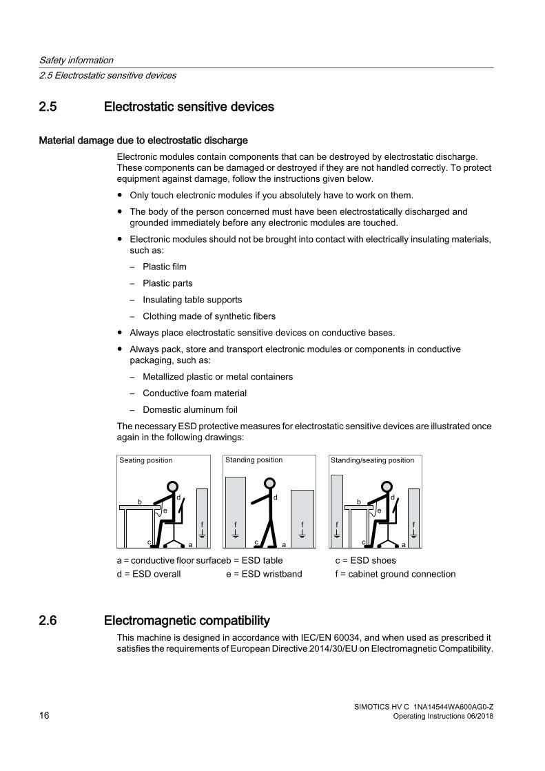
The necessary ESD protective measures for electrostatic sensitive devices are illustrated once again in the following drawings:
a = conductive floor surfaceb = ESD table c = ESD shoesd = ESD overall e = ESD wristband f = cabinet ground connection
2.6 Electromagnetic compatibilityThis machine is designed in accordance with IEC/EN 60034, and when used as prescribed it satisfies the requirements of European Directive 2014/30/EU on Electromagnetic Compatibility.
Safety information2.5 Electrostatic sensitive devices
SIMOTICS HV C 1NA14544WA600AG0-Z16 Operating Instructions 06/2018

2.7 Interference immunityBy selecting suitable signal cables and evaluation units, companies operating complete plants and systems must ensure that the interference immunity of the machine is not diminished.
2.8 Influence on the line power supply through a strongly irregular torqueA strongly irregular torque, for example with the drive of a reciprocating motor, forces a non-sinusoidal motor current. The emerging harmonics can have an impermissible influence on the line power supply via the connection lines.
2.9 Electromagnetic fields when operating electrical power engineering installations
Interference to electronic devices caused by electrical power equipmentElectrical power equipment generate electric fields during operation. Potentially lethal malfunctions can occur in medical implants, e.g. pacemakers, in the vicinity of electrical power equipment. Data may be lost on magnetic or electronic data carriers.
● It is forbidden for people with pacemakers to enter the vicinity of the machine.
● Protect the personnel working in the plant by taking appropriate measures, such as erecting identifying markings, safety barriers and warning signs and giving safety talks.
● Observe the nationally applicable health and safety regulations.
● Do not carry any magnetic or electronic data media.
Safety information2.7 Interference immunity
SIMOTICS HV C 1NA14544WA600AG0-ZOperating Instructions 06/2018 17

Safety information2.9 Electromagnetic fields when operating electrical power engineering installations
SIMOTICS HV C 1NA14544WA600AG0-Z18 Operating Instructions 06/2018
Description 3Applications
This electrical machine is designed for driving rotating machines in industrial environments and also for energy conversion. It is characterized by a high level of safety, long lifetime, and overall reliability.
For details of the machine supplied and the permissible operating conditions, refer to the "Technical data and drawings" (Page 101) section in the Appendix of these Operating Instructions.
The machine was designed in accordance with the ordering party's specification and may only be used for the contractually agreed purpose.
WARNING
Risk of explosion
This machine is not designed for use in hazardous areas. An explosion can occur if the machine is operated in these areas. This can result in death, serious injury or material damage.● Never operate this machine in hazardous areas.
Machine designThe regulations and standards used as the basis to design and test this machine are stamped on the rating plate.
The machine design basically complies with the subsequent standards. Please refer to the EU Declaration of Conformity for the versions of the harmonized standards referenced.
Table 3-1 Machine design
Feature StandardRating and performance IEC/EN 60034‑1Degree of protection IEC/EN 60034‑5Cooling IEC/EN 60034‑6Type of construction IEC/EN 60034‑7Terminal markings and direction of rotation IEC/EN 60034‑8Noise emission IEC/EN 60034‑9Starting characteristics, rotating electrical machines IEC/EN 60034‑12*Vibration severity grades IEC/EN 60034‑14Vibration limits DIN ISO 10816-3
* For machines in line operation only
SIMOTICS HV C 1NA14544WA600AG0-ZOperating Instructions 06/2018 19
See alsoQuality documents (Page 103)
Rating plateThe rating plate shows the identification data and the most important technical data. The data on the rating plate and the contractual agreements define the limits of proper usage.
Line operationThe motor is supplied from the line system.
If you connect the machine to a converter, the machine can be damaged. Operate the machine only on the electrical supply system.
CoolingThe cooling system is designed as a closed, internal cooling circuit. The machine power loss is dissipated partially via heat conduction and partially via the cooling air at the cooling water flowing through the water jacket. A shaft-mounted fan ensures circulation of the cooling air.
RotorThe rotor is designed as a squirrel-cage rotor. The number and design of the shaft extensions are shown and described in the technical data.
Supplementary devicesTemperature sensors are integrated in the stator winding to monitor the winding temperature. Various supplementary devices can be integrated or mounted, depending on the order. These include, for example, anti-condensation heating to prevent condensation or temperature sensors for monitoring bearings.
Paint finish The machine is painted according to the instructions in your order.
Description
SIMOTICS HV C 1NA14544WA600AG0-Z20 Operating Instructions 06/2018
Preparations for use 4Good planning and preparation of machine applications are essential in terms of keeping installation simple and avoiding errors, ensuring safe operation, and allowing access to the machine for servicing and corrective maintenance.
This chapter outlines what you need to consider when configuring your plant in relation to this machine and the preparations you need to make before the machine is delivered.
4.1 Safety-related aspects to consider when configuring the plantA number of residual risks are associated with the machine. These are described in the chapter titled "Safety information" (Page 13) and in related sections.
Take appropriate safety precautions (covers, barriers, markings, etc.) to ensure the machine is operated safely within your plant.
4.2 Observing the operating modeObserve the machine's operating mode. Use a suitable control system to prevent overspeeds, thus protecting the machine from damage.
4.3 Cooling water quality● The cooling water must circulate in a closed cooling circuit.
● Avoid fluctuations in the oxygen content of the cooling water.
● The cooling system is maintenance-free provided cooling water of the specified quality is used.
NoteOrder-specific agreements
Observe any order-specific agreements regarding the cooling water specification. These might deviate from the named cooling water specification.
Cooling water specification
Characteristic Specified as Measured value German unitary proce‐dure
Currently ISO / alterna‐tive
pH 7.5 - 10 DIN 38404-5 (Z) ISO 10523Conductivity <600 µS/cm DIN 38404-8 (Z) ISO 7888
SIMOTICS HV C 1NA14544WA600AG0-ZOperating Instructions 06/2018 21
Chloride Cl <150 mg/l DIN 38405-1 ISO 9297Manganese Mn <0.05 mg/l DIN 38406-2 ISO 6333 /
ISO 11885Fluoride F <0.05 mg/l DIN 38405-4 ISO 10359-1Sulfate SO4
2- <150 mg/l DIN 38405-5 ISO 10304Copper Cu = Total copper <0.1 mg/l DIN 38406-7 ISO 8288 /
ISO 11885Silicic acid SiO2 <25 mg/l F1 (DIN 38407-1) ISO 16264Free carbon dioxide CO2 0 mg/l G1 (DIN 38408-1) -Total salts <1000 mg/l DIN 38409-1 -Nitrate NO3
- <20 mg/l DIN 38405-9 ISO 7890-1 (Z) / ISO 10304
Suspended matter <10 mg/l DIN 38409-2 ISO 11923Permanganate consump‐tion
O <12 mg/l H4 (DIN 38409-5) ISO 8467
Total hardness Mg+Ca <12 °DH DIN 38409-6 ISO 6059Carbonate hardness HCO3
- <12 °DH DIN 38404-10 ISO 9963-1Ammonium content N ISO 11732 /
NH4+ ISO 14911
<10 mg/l DIN 38406-5 ISO 11732 / ISO 14911
Iron content Fe = Total iron <0.2 mg/l DIN 38406-1 ISO 6332 / ISO 11885
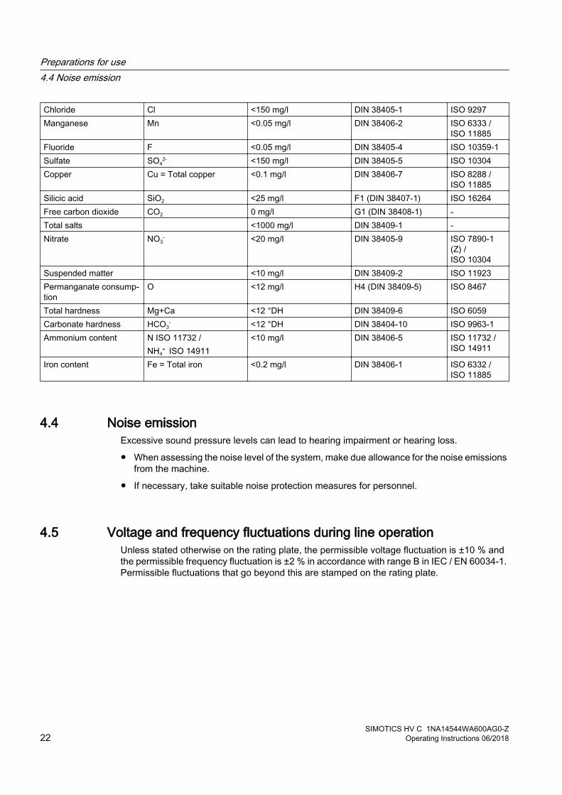
4.4 Noise emissionExcessive sound pressure levels can lead to hearing impairment or hearing loss.
● When assessing the noise level of the system, make due allowance for the noise emissions from the machine.
● If necessary, take suitable noise protection measures for personnel.
4.5 Voltage and frequency fluctuations during line operationUnless stated otherwise on the rating plate, the permissible voltage fluctuation is ±10 % and the permissible frequency fluctuation is ±2 % in accordance with range B in IEC / EN 60034-1. Permissible fluctuations that go beyond this are stamped on the rating plate.
Preparations for use4.4 Noise emission
SIMOTICS HV C 1NA14544WA600AG0-Z22 Operating Instructions 06/2018

Under operating conditions a machine may sometimes have to be operated outside the limits of range A.
● Exceeding the permissible tolerances for voltage and frequency can lead to an impermissibly high temperature rise of the winding. This can result in long-term damage to the machine.
● Limit exceptions of this sort with regard to the values that arise, how often, and for how long they occur.
● Where possible and within a reasonable time take corrective actions such as reducing the power. In this way you can avoid that the service life of the machine is reduced as a result of thermal aging.
4.6 Phase synchronization during supply system switchingDamage to the machine may be caused when switching to another supply system with different phasing.
● The phasing must be synchronized during switching. Use appropriate means to synchronize the phasing.
4.7 System-inherent frequenciesExcessively high vibration levels and system resonances can damage the machine set.
● Configure and match the system consisting of the foundation and machine set in such a way that no system resonances can arise and result in the permissible vibration levels being exceeded.
● The vibration values according to DIN ISO 10816-3 must not be exceeded.
4.8 Torsional loading of the drive train due to faults in the electrical supplyIn the event of faults in the electrical connection, such as line switching operations with a residual field or short circuit at the terminals, excessive air gap torques can occur. These excessive air gap torques can lead to additional mechanical torsional loads on the shaft assembly.
If the configuration does not correctly recognize the mechanical torsional loadings of the shaft assembly, this can lead to serious damage to the machine. This can result in death, serious injury or material damage.
● When planning the system, make due allowance for the maximum air gap torques that can occur. This data can be found in the "Electrical data".
The system planner is responsible for the entire drive train.
Preparations for use4.6 Phase synchronization during supply system switching
SIMOTICS HV C 1NA14544WA600AG0-ZOperating Instructions 06/2018 23

4.9 Switching high-voltage motorsIf vacuum circuit breakers and vacuum contactors are used, then what are known as multiple restrikes can occur when the machine is switched off. This depends on various factors, such as:
● Arc-extinguishing principle of the switch
● Machine size
● Length of the power supply cable
● System capacitance, etc.
A surge suppressor to ground is installed in the switchgear between the circuit breaker and the cable termination for each of the three conductors. The level of protection for the machine windings is sufficient when the limiter is correctly selected (machine rated voltage / response voltage).
ExampleThis current limit corresponds to the following upper power limits, depending on the relationship between the starting current IA and rated current IN and on the voltage dip (up to approximately 20%) while the machine is starting up:
Table 4-1 Power limits
Rated voltage VN Power limit3 kV 750 kW6 kV 1500 kW10 kV 2500 kW
See alsoPrior to commissioning (Page 59)
4.10 Thermal protection The machine is equipped with measuring equipment to directly monitor the motor temperature to protect the machine against overheating during operation. Plan a corresponding circuit for monitoring. More information is provided in Technical Data.
4.11 Transport and storageObserve the following when carrying out any work on the machine:
● Comply with the general safety instructions (Page 13)
● Comply with the applicable national and sector-specific regulations.
● When using the machine within the European Union, comply with the specifications laid down in EN 50110‑1 regarding safe operation of electrical equipment.
Preparations for use4.9 Switching high-voltage motors
SIMOTICS HV C 1NA14544WA600AG0-Z24 Operating Instructions 06/2018

4.11.1 Transport markingsThe packing differs depending on the transport type and size. If not otherwise contractually agreed, the packaging corresponds to the packing guidelines for International Standards for Phytosanitary Measures (ISPM).
Note the symbols which appear on the packing. These have the following meanings:
Top Fragile material Keep dry Keep cool Center of gravity
Do not use hand hook
Attach here
4.11.2 Checking the deliveryThe components are assembled on an individual basis. When you take receipt of the delivery, please check immediately whether the scope of the delivery matches up with the accompanying documents. No claims relating to defects/items missing from the delivery will be accepted if they are submitted at a later date.
● Report any apparent transport damage to the delivery agent immediately.
● Immediately report any apparent defects/missing components to your contact partner.
These Operating Instructions are part of the scope of delivery; keep them in a location where they can be easily accessed.
4.11.3 Checking the load handling attachmentsInspect the load handling attachments such as the load trestles, lifting eyes and ring bolts and also the lifting gear, before lifting the machine:
● Inspect the load handling attachments on the machine for possible damage. Replace any load suspension equipment that is found to be damaged.
● Before use, check that the load suspension equipment is correctly attached.
● When lifting the machine, use only approved and undamaged lifting gear of sufficient rated capacity. Check the lifting gear prior to its use.
WARNING
The machine can be dropped
If the load handling attachments and lifting gear are damaged or not correctly secured, the machine may be dropped during lifting. This can result in death, serious injury or material damage. ● Inspect the load handling attachments and lifting gear before use.
Preparations for use4.11 Transport and storage
SIMOTICS HV C 1NA14544WA600AG0-ZOperating Instructions 06/2018 25

WARNING
Danger if the machine falls
The lifting lugs on the machine are designed only for the weight of the machine. If a machine set is lifted and transported on a single machine, this can lead to mechanical failure of the lifting lug. The machine or machine set may fall. This can result in death, serious injury or material damage.● Do not lift machine sets by attaching lifting tackle to the individual machines.● Use only the equipment provided, e.g. the openings or lugs on the base plates, for
transporting machine sets. Note the maximum capacity of the lifting lug.
4.11.4 Lifting and transportation● Persons driving cranes and fork-lift trucks must hold appropriate licenses.
● If the motor is packed, depending on the weight, size and on-site conditions, lift crates and transport frames using a fork-lift truck or a crane with slings. Use a crane or fork-lift truck suitable for the load.
● When lifting the machine, use only approved and undamaged sling guides and spreaders of sufficient rated capacity. Check this equipment before using it. The weight of the machine is shown on the rating plate.
● If adapter flange and adapter plates are also supplied, then lift them and transport these parts separately. The load suspension equipment for the motor is not rated for lifting the motor with mounted adapter flange is or adapter plates
Preparations for use4.11 Transport and storage
SIMOTICS HV C 1NA14544WA600AG0-Z26 Operating Instructions 06/2018
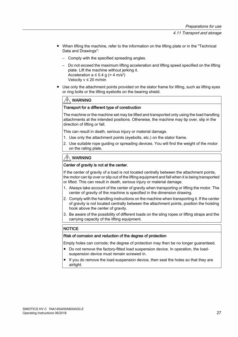
● When lifting the machine, refer to the information on the lifting plate or in the "Technical Data and Drawings":
– Comply with the specified spreading angles.
– Do not exceed the maximum lifting acceleration and lifting speed specified on the lifting plate. Lift the machine without jerking it.Acceleration a ≤ 0.4 g (≈ 4 m/s2)Velocity v ≤ 20 m/min
● Use only the attachment points provided on the stator frame for lifting, such as lifting eyes or ring bolts or the lifting eyebolts on the bearing shield.
WARNING
Transport for a different type of construction
The machine or the machine set may be lifted and transported only using the load handling attachments at the intended positions. Otherwise, the machine may tip over, slip in the direction of lifting or fall.
This can result in death, serious injury or material damage.1. Use only the attachment points (eyebolts, etc.) on the stator frame.2. Use suitable rope guiding or spreading devices. You will find the weight of the motor
on the rating plate.
WARNING
Center of gravity is not at the center.
If the center of gravity of a load is not located centrally between the attachment points, the motor can tip over or slip out of the lifting equipment and fall when it is being transported or lifted. This can result in death, serious injury or material damage.1. Always take account of the center of gravity when transporting or lifting the motor. The
center of gravity of the machine is specified in the dimension drawing. 2. Comply with the handling instructions on the machine when transporting it. If the center
of gravity is not located centrally between the attachment points, position the hoisting hook above the center of gravity.
3. Be aware of the possibility of different loads on the sling ropes or lifting straps and the carrying capacity of the lifting equipment.
NOTICE
Risk of corrosion and reduction of the degree of protection
Empty holes can corrode; the degree of protection may then be no longer guaranteed.● Do not remove the factory-fitted load suspension device. In operation, the load-
suspension device must remain screwed in.● If you do remove the load-suspension device, then seal the holes so that they are
airtight.
Preparations for use4.11 Transport and storage
SIMOTICS HV C 1NA14544WA600AG0-ZOperating Instructions 06/2018 27

WARNING
Lifting equipment can break at low temperatures
At low temperatures, the material of the lifting equipment can become brittle. When lifting and transporting, the lifting equipment can tear off and the motor might be dropped.
This can result in death, serious injury, or material damage.● Only lift the machine using the lifting equipment at temperatures that are not below -20 °C. ● Alternatively, warm up the lifting equipment or lift the machine in a different way.
4.11.5 Working on the underside of the machine● Never remain under or in the immediate vicinity of the machine when it is lifted. If the lifting
gear or load handling attachments were to fail, the machine could fall. This can result in death, serious injury or material damage.
● In order to gain easy and safe access to the underside of the machine, place it in a secure and raised position.
4.11.6 StorageYou must correctly store the machine if you do not install and use it after it has been delivered.
NOTICE
Bearing seizure damage if incorrectly stored
If storage conditions are inappropriate there is a risk of bearing seizure damage. Resulting damage can include scoring (brinelling) and corrosion. ● Follow the storage guidelines.
Preconditions and preparations● Only store goods in undamaged packaging. Unpack the goods if the packaging is damaged.
Correctly store the goods corresponding to the type.
● Repair any damage to the packaging before putting the equipment into storage insofar as this is necessary to ensure proper storage conditions.
Preparations for use4.11 Transport and storage
SIMOTICS HV C 1NA14544WA600AG0-Z28 Operating Instructions 06/2018

General instructions for storageWherever possible, store the machine in a storage room. The place of storage must satisfy the following general conditions:
● Select a sufficiently sized dry and horizontal place of storage that is above flood level and free of vibration (veff ≤ 0.2 mm/s).
– The place of storage must be well ventilated as well as free of dust and frost. Provide protection against extreme weather conditions. Ensure that the temperature remains stable in the range from 10 °C to 50 °C – or 50 °F to 120 °F. If there is a risk of condensation, the room temperature should be approx. 10 K above the outside temperature. The temperature should not fall below ‑20° C.
– The relative humidity of the air should be less than 60%.
– The floor of the place of storage must be sufficiently strong. The maximum permissible floor loading or storage compartment loading may not be exceeded.
– The ambient air must not contain any harmful gases.
● Protect the machine from shocks and humidity.
● Position machines, devices and crates on pallets, wooden beams or foundations that protect them against rising damp and water.
● Ensure that the air circulation under the equipment is not impeded.
– Place wooden spacer blocks between the covers and the machine.
– Covers or tarpaulins must not trail on the floor around the machine.
Storing outdoorsWhen storing the machines outside, the storage location must comply with the following conditions:
● The ground must be sufficiently strong. Prevent the machine from sinking into the ground.
● Covers or tarpaulins used to protect the equipment against the weather must not make contact with the surfaces of the equipment. Otherwise air circulation under the stored items will be prevented.
Protection against humidity If a dry storage space is not available, protect the machine as follows against humidity:
● Wrap the machine in humidity-absorbent material.
● Wrap the machine in plastic film:
– Place a humidity meter inside the plastic film.
– Place desiccant within the plastic film.
– Pack the machine air-tight.
● Inspect the machine regularly.
Preparations for use4.11 Transport and storage
SIMOTICS HV C 1NA14544WA600AG0-ZOperating Instructions 06/2018 29
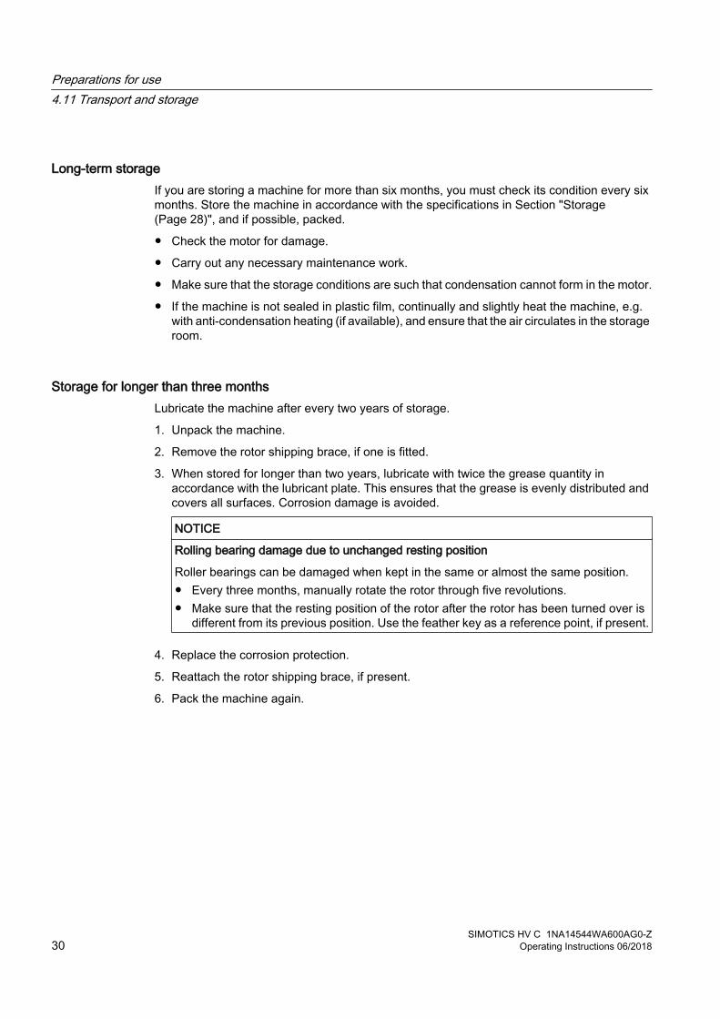
Long-term storage If you are storing a machine for more than six months, you must check its condition every six months. Store the machine in accordance with the specifications in Section "Storage (Page 28)", and if possible, packed.
● Check the motor for damage.
● Carry out any necessary maintenance work.
● Make sure that the storage conditions are such that condensation cannot form in the motor.
● If the machine is not sealed in plastic film, continually and slightly heat the machine, e.g. with anti-condensation heating (if available), and ensure that the air circulates in the storage room.
Storage for longer than three monthsLubricate the machine after every two years of storage.
1. Unpack the machine.
2. Remove the rotor shipping brace, if one is fitted.
3. When stored for longer than two years, lubricate with twice the grease quantity in accordance with the lubricant plate. This ensures that the grease is evenly distributed and covers all surfaces. Corrosion damage is avoided.
NOTICE
Rolling bearing damage due to unchanged resting position
Roller bearings can be damaged when kept in the same or almost the same position.● Every three months, manually rotate the rotor through five revolutions. ● Make sure that the resting position of the rotor after the rotor has been turned over is
different from its previous position. Use the feather key as a reference point, if present.
4. Replace the corrosion protection.
5. Reattach the rotor shipping brace, if present.
6. Pack the machine again.
Preparations for use4.11 Transport and storage
SIMOTICS HV C 1NA14544WA600AG0-Z30 Operating Instructions 06/2018

4.11.7 Protection against corrosionIf the machine is stored in dry conditions, then apply the subsequently listed anti-corrosion measures:
● Storage up to six months:Apply a coat of corrosion protective compound to all accessible bare metal parts such as the exposed shaft extension, flange or machine feet.
● Storage for longer than six months:Apply a coat of long-term anti-corrosion agent to all accessible bare parts.
● Inspect the machine regularly and if necessary, apply an additional coating of corrosion protection.
Document all preservation measures taken so that they can be reversed before the machines are put back into service.
4.11.8 Protecting the cooling water circuit during storageWhen supplied, the machine is not filled with cooling water.
Protecting the cooling circuit against corrosionYou protect the cooling circuit against corrosion when the machine has already been in operation and is then placed in storage or put out of operation.
1. Completely drain the cooling ducts. Blow out the cooling water ducts with compressed air.
1. Close and seal the intake and discharge.
Preparations for use4.11 Transport and storage
SIMOTICS HV C 1NA14544WA600AG0-ZOperating Instructions 06/2018 31

Preparations for use4.11 Transport and storage
SIMOTICS HV C 1NA14544WA600AG0-Z32 Operating Instructions 06/2018

Assembly 5Observe the following when carrying out any work on the machine:
● Comply with the general safety instructions (Page 13)
● Comply with the applicable national and sector-specific regulations.
● When using the machine within the European Union, comply with the specifications laid down in EN 50110‑1 regarding safe operation of electrical equipment.
Loss of conformity with European directivesIn the delivery state, the machine corresponds to the requirements of the European directives. Unauthorized changes or modifications to the machine lead to the loss of conformity with European directives and the loss of warranty.
5.1 Preparations for installation
5.1.1 Requirements for installationThe following requirements must be satisfied prior to starting installation work:
● Staff have access to the relevant installation instructions and operating instructions.
● The machine is unpacked and ready for mounting at the installation location.
NoteFurther Information
Further machine-specific information for installation can be found in Chapter "Technical data and drawings" (Page 101).
NoteMeasure the insulation resistance of the winding before starting installation work
Measure the insulation resistance of the winding before starting any installation work. If the insulation resistance lies below the specified value, take appropriate remedial measures. These remedial measures may necessitate the machine being removed again and transported.
See alsoInsulation resistance and polarization index (Page 34)
SIMOTICS HV C 1NA14544WA600AG0-ZOperating Instructions 06/2018 33

Damage to mounted parts and components as a result of high temperaturesThe motor components get very hot during operation. High temperatures can damage parts mounted by customers, such as cables manufactured out of materials that are not heat resistant.
● Temperature-sensitive parts must not come in contact with or be attached to components mounted on the machine.
● Only use heat-resistant mounting parts. The connecting cables and cable entries must be suitable for the particular application.
5.1.2 Insulation resistance and polarization indexMeasuring the insulation resistance and polarization index (PI) provides information on the condition of the machine. It is therefore important to check the insulation resistance and the polarization index at the following times:
● Before starting up a machine for the first time
● After an extended period in storage or downtime
● Within the scope of maintenance work
The following information is provided regarding the state of the winding insulation:
● Is the winding head insulation conductively contaminated?
● Has the winding insulation absorbed moisture?
As such, you can determine whether the machine needs commissioning or any necessary measures such as cleaning and/or drying the winding:
● Can the machine be put into operation?
● Must the windings be cleaned or dried?
Detailed information on testing and the limit values can be found here:
"Testing the insulation resistance and polarization index" (Page 35)
Assembly5.1 Preparations for installation
SIMOTICS HV C 1NA14544WA600AG0-Z34 Operating Instructions 06/2018
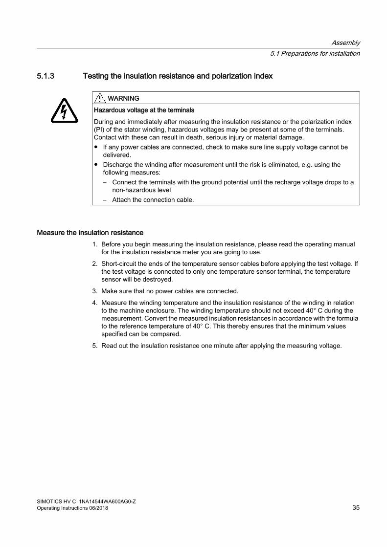
5.1.3 Testing the insulation resistance and polarization index
WARNING
Hazardous voltage at the terminals
During and immediately after measuring the insulation resistance or the polarization index (PI) of the stator winding, hazardous voltages may be present at some of the terminals. Contact with these can result in death, serious injury or material damage.● If any power cables are connected, check to make sure line supply voltage cannot be
delivered.● Discharge the winding after measurement until the risk is eliminated, e.g. using the
following measures:– Connect the terminals with the ground potential until the recharge voltage drops to a
non-hazardous level– Attach the connection cable.
Measure the insulation resistance1. Before you begin measuring the insulation resistance, please read the operating manual
for the insulation resistance meter you are going to use.
2. Short-circuit the ends of the temperature sensor cables before applying the test voltage. If the test voltage is connected to only one temperature sensor terminal, the temperature sensor will be destroyed.
3. Make sure that no power cables are connected.
4. Measure the winding temperature and the insulation resistance of the winding in relation to the machine enclosure. The winding temperature should not exceed 40° C during the measurement. Convert the measured insulation resistances in accordance with the formula to the reference temperature of 40° C. This thereby ensures that the minimum values specified can be compared.
5. Read out the insulation resistance one minute after applying the measuring voltage.
Assembly5.1 Preparations for installation
SIMOTICS HV C 1NA14544WA600AG0-ZOperating Instructions 06/2018 35
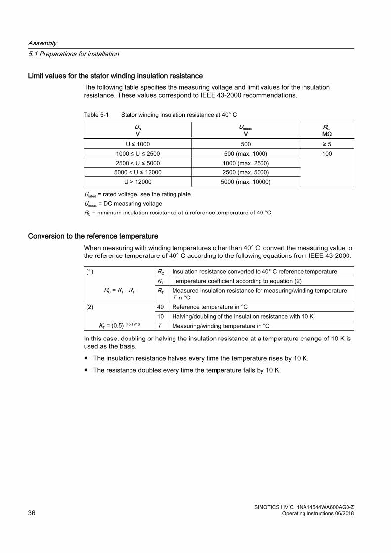
Limit values for the stator winding insulation resistanceThe following table specifies the measuring voltage and limit values for the insulation resistance. These values correspond to IEEE 43‑2000 recommendations.
Table 5-1 Stator winding insulation resistance at 40° C
UNV
Umeas V
RC MΩ
U ≤ 1000 500 ≥ 51000 ≤ U ≤ 2500 500 (max. 1000) 1002500 < U ≤ 5000 1000 (max. 2500)
5000 < U ≤ 12000 2500 (max. 5000)U > 12000 5000 (max. 10000)
Urated = rated voltage, see the rating plateUmeas = DC measuring voltageRC = minimum insulation resistance at a reference temperature of 40 °C
Conversion to the reference temperatureWhen measuring with winding temperatures other than 40° C, convert the measuring value to the reference temperature of 40° C according to the following equations from IEEE 43-2000.
(1)
RC = KT · RT
RC Insulation resistance converted to 40° C reference temperatureKT Temperature coefficient according to equation (2)RT Measured insulation resistance for measuring/winding temperature
T in °C(2)
KT = (0.5) (40-T)/10
40 Reference temperature in °C10 Halving/doubling of the insulation resistance with 10 KT Measuring/winding temperature in °C
In this case, doubling or halving the insulation resistance at a temperature change of 10 K is used as the basis.
● The insulation resistance halves every time the temperature rises by 10 K.
● The resistance doubles every time the temperature falls by 10 K.
Assembly5.1 Preparations for installation
SIMOTICS HV C 1NA14544WA600AG0-Z36 Operating Instructions 06/2018

For a winding temperature of approx. 25° C, the minimum insulation resistances are 20 MΩ (U ≤ 1000 V) or 300 MΩ (U > 1000 V). The values apply for the complete winding to ground. Twice the minimum values apply to the measurement of individual assemblies.
● Dry, new windings have an insulation resistance of between 100 and 2000 MΩ, or possibly even higher values. An insulation resistance value close to the minimum value could be due to moisture and/or dirt accumulation. The size of the winding, the rated voltage and other characteristics affect the insulation resistance and may need to be taken into account when determining measures.
● Over its operating lifetime, the motor winding insulation resistance can drop due to ambient and operational influences. Calculate the critical insulation resistance value depending on the rated voltage by multiplying the rated voltage (kV) by the specific critical resistance value. Convert the value for the current winding temperature at the time of measurement, see above table.
Measuring the polarization index1. To determine the polarization index, measure the insulation resistances after one minute
and ten minutes.
2. Express the measured values as a ratio:PI = Rinsul 10 min / Rinsul 1 minMany measuring devices display these values automatically following the measurement.
For insulation resistances > 5000 MΩ, the measurement of the PI is no longer meaningful and consequently not included in the assessment.
R(10 min) / R(1 min) Assessment≥ 2 Insulation in good condition< 2 Dependent on the complete diagnosis of the insulation
NOTICE
Damage to insulation
If the critical insulation resistance is reached or undershot, this can damage the insulation and cause voltage flashovers. ● Contact the service center (Page 99).● If the measured value is close to the critical value, you must subsequently check the
insulation resistance at shorter intervals.
Assembly5.1 Preparations for installation
SIMOTICS HV C 1NA14544WA600AG0-ZOperating Instructions 06/2018 37

5.1.4 Preparing the mating faces● Ensure that the foundation faces are flat and free of contaminations.
NoteShims
To establish a defined mounting surface, you can order shims (option L31) from our Service Center.
● Check the dimensions of the mounting-foot holes.
See alsoTechnical data and drawings (Page 101)
Removing anti-corrosion protection (Page 43)
Lifting the machine (Page 41)
Service and Support (Page 99)
5.2 Lift the machine to where it will be installed, and position it
5.2.1 Checking the load handling attachmentsInspect the load handling attachments such as the load trestles, lifting eyes and ring bolts and also the lifting gear, before lifting the machine:
● Inspect the load handling attachments on the machine for possible damage. Replace any load suspension equipment that is found to be damaged.
● Before use, check that the load suspension equipment is correctly attached.
● When lifting the machine, use only approved and undamaged lifting gear of sufficient rated capacity. Check the lifting gear prior to its use.
WARNING
The machine can be dropped
If the load handling attachments and lifting gear are damaged or not correctly secured, the machine may be dropped during lifting. This can result in death, serious injury or material damage. ● Inspect the load handling attachments and lifting gear before use.
Assembly5.2 Lift the machine to where it will be installed, and position it
SIMOTICS HV C 1NA14544WA600AG0-Z38 Operating Instructions 06/2018

5.2.2 Preconditions for correct alignment and secure attachment To align the machine correctly and fasten it securely, you require detailed specialist knowledge of the following necessary measures:
● Preparing the foundation
● Select and mount the coupling
● Measure the radial and axial eccentricity
● Position the machine
If you are not familiar with the prescribed measures and procedures, make use of the services offered by the Service Center (Page 99).
5.2.3 Mounting the output elements
Balance quality The rotor is dynamically balanced. For shaft extensions with featherkeys, the balancing type is specified using the following coding on the face of the drive end of the shaft:
● "H" means balancing with a half feather key
● "F" means balancing with a whole feather key.
Figure 5-1 Balancing type on the drive-end side
Assembly5.2 Lift the machine to where it will be installed, and position it
SIMOTICS HV C 1NA14544WA600AG0-ZOperating Instructions 06/2018 39

Pushing on the power output elements ● Prerequisites:
– The coupling and/or the output element must be appropriately dimensioned for the operating case at hand. The balance quality must satisfy the following requirements.
– Comply with the coupling manufacturer's instructions.
– Make sure that the balancing type of the transmission element correctly matches the type of balance of the rotor.
– Use only ready drilled and balanced transmission elements. Check the hole diameters and the balancing status before pulling them on. Thoroughly clean the shaft extension.
● Pulling on:
– Warm up the transmission elements to expand them before pulling them on. Select the temperature difference for the heating process to suit the coupling diameter, fit and material. See the coupling manufacturer's instructions.
– Power output elements may only be pushed on or pulled off with the correct equipment. The output element must be pulled on in one continuous operation using the front thread holes in the shaft or pulled on by hand.
– Do not strike it with a hammer, as this would damage the bearings.
Shaft extensions with feather key To maintain the balancing quality, you have the following options:
● If the output element is shorter than the feather key with balancing type "H", then you must machine off the section of feather key protruding from the shaft contour and output element. Alternatively, ensure that the weights are compensated to achieve the appropriate balance quality.
● If the transmission element is drawn up on to the shoulder of the shaft, you must ensure that the part of the coupling groove where the feather key is not inserted is taken into consideration when balancing the coupling.
The following applies for all 2-pole machines and 4-pole machines with a frequency ≥ 60 Hz:
● The feather key must be shortened if the coupling hub is shorter than the feather key.
● The center of gravity of the coupling half should be within the length of the shaft end.
● The coupling used must be prepared for system balancing.The number of poles of the machine is specified on the rating plate (in the designation of the motor type).
Assembly5.2 Lift the machine to where it will be installed, and position it
SIMOTICS HV C 1NA14544WA600AG0-Z40 Operating Instructions 06/2018

WARNING
The feather key can fall out
The feather keys are only locked against falling out during shipping. If a machine with two shaft extensions does not have an output element on one shaft extension, the feather key can fall out during operation.
Death or serious injury can result.● If the machine is to be operated without output elements, secure the feather key on the
free shaft extension so that it cannot be flung out. ● To avoid imbalance, for balancing type "H", reduce the weight of the feather key to 60 %
of the original weight.
5.2.4 Lifting the machine● Persons driving cranes and fork-lift trucks must hold appropriate licenses.
● If the motor is packed, depending on the weight, size and on-site conditions, lift crates and transport frames using a fork-lift truck or a crane with slings. Use a crane or fork-lift truck suitable for the load.
● When lifting the machine, use only approved and undamaged sling guides and spreaders of sufficient rated capacity. Check this equipment before using it. The weight of the machine is shown on the rating plate.
● If adapter flange and adapter plates are also supplied, then lift them and transport these parts separately. The load suspension equipment for the motor is not rated for lifting the motor with mounted adapter flange is or adapter plates
Assembly5.2 Lift the machine to where it will be installed, and position it
SIMOTICS HV C 1NA14544WA600AG0-ZOperating Instructions 06/2018 41

● When lifting the machine, refer to the information on the lifting plate or in the "Technical Data and Drawings":
– Comply with the specified spreading angles.
– Do not exceed the maximum lifting acceleration and lifting speed specified on the lifting plate. Lift the machine without jerking it.Acceleration a ≤ 0.4 g (≈ 4 m/s2)Velocity v ≤ 20 m/min
● Use only the attachment points provided on the stator frame for lifting, such as lifting eyes or ring bolts or the lifting eyebolts on the bearing shield.
WARNING
Transport for a different type of construction
The machine or the machine set may be lifted and transported only using the load handling attachments at the intended positions. Otherwise, the machine may tip over, slip in the direction of lifting or fall.
This can result in death, serious injury or material damage.1. Use only the attachment points (eyebolts, etc.) on the stator frame.2. Use suitable rope guiding or spreading devices. You will find the weight of the motor
on the rating plate.
WARNING
Center of gravity is not at the center.
If the center of gravity of a load is not located centrally between the attachment points, the motor can tip over or slip out of the lifting equipment and fall when it is being transported or lifted. This can result in death, serious injury or material damage.1. Always take account of the center of gravity when transporting or lifting the motor. The
center of gravity of the machine is specified in the dimension drawing. 2. Comply with the handling instructions on the machine when transporting it. If the center
of gravity is not located centrally between the attachment points, position the hoisting hook above the center of gravity.
3. Be aware of the possibility of different loads on the sling ropes or lifting straps and the carrying capacity of the lifting equipment.
NOTICE
Risk of corrosion and reduction of the degree of protection
Empty holes can corrode; the degree of protection may then be no longer guaranteed.● Do not remove the factory-fitted load suspension device. In operation, the load-
suspension device must remain screwed in.● If you do remove the load-suspension device, then seal the holes so that they are
airtight.
Assembly5.2 Lift the machine to where it will be installed, and position it
SIMOTICS HV C 1NA14544WA600AG0-Z42 Operating Instructions 06/2018

5.2.5 Working on the underside of the machine● Never remain under or in the immediate vicinity of the machine when it is lifted. If the lifting
gear or load handling attachments were to fail, the machine could fall. This can result in death, serious injury or material damage.
● In order to gain easy and safe access to the underside of the machine, place it in a secure and raised position.
5.2.6 Removing anti-corrosion protectionMachined, bare metal surfaces of machine parts and small components such as screws, bolts, wedges, feather keys, and dowel pins, are treated with an anti-corrosion agent.
Carefully remove the anti-corrosion agent and immediately start the installation work.
Bright surfaces on machine parts● Use petroleum, petroleum ether, or a similar solvent or detergent to remove the anti-
corrosion coating from the machined surfaces of machine parts and from small components.
NOTICE
Paintwork damage
Make sure that the cleaning agent or solvent does not come into contact with any painted surfaces, as this could damage the lacquer.
● Use a suitable solvent to soften thick layers of anti-corrosion agent. Then push off the softened layers using a piece of hardwood (approximately 10 x 10 x 1 cm). Do not sand the protective coating down or scrape it off.
NOTICE
Do not use metal tools.
Do not use metal objects such as scrapers, spatulas, or plates to remove the anti-corrosion protection,
as this could damage the surfaces of the machine parts.
● Lightly oil the depreserved surfaces.
Thread and fastening parts● Remove the anti-corrosion protection from bolts and tapered pins.
● Use the appropriate tap or cutting die to shave the tapped holes of machine parts and threads of screws, etc. See the drawings for the relevant male and female thread dimensions.
● Use dry compressed air to purge the shaved tapped holes.
● Lightly oil the depreserved threads.
Assembly5.2 Lift the machine to where it will be installed, and position it
SIMOTICS HV C 1NA14544WA600AG0-ZOperating Instructions 06/2018 43

Burrs and pressure marks● Check the machine parts, as well as fastening and fixing elements, for burrs or pressure
marks. Use a smoothing file to carefully remove any such burrs/pressure marks.
● Only whetstones may be used to smooth finished surfaces.
5.2.7 Putting the machine down
RequirementsThe following preconditions must be satisfied before setting down the machine at the installation location:
● The mating faces must be clean.
● The anti-corrosion protection paint has been removed from the mating faces, such as the machine mounting feet, flange, ...
● There is no condensation present within the machine.
Setting down the machine● Set down the machine slowly and carefully at the installation location to avoid any impact.
See alsoRemoving anti-corrosion protection (Page 43)
5.2.8 Draining condensationUnder the following conditions it is possible that condensation may accumulate within the machine:
● Wide fluctuations in the ambient temperature, such as direct sunlight combined with high atmospheric humidity
● Intermittent operation or load fluctuations during operation
NOTICE
Damage due to condensate
If the stator winding is damp, its insulation resistance will be reduced. This can result in voltage flashovers that can seriously damage the windings. Condensate can also cause rust to form within the machine.
Ensure that condensate can drain away.
Assembly5.2 Lift the machine to where it will be installed, and position it
SIMOTICS HV C 1NA14544WA600AG0-Z44 Operating Instructions 06/2018

Ensure that condensate can drain awayIn the bearing shields on the DE and NDE, water drainage holes are situated below or opposite the regreasing devices. They are sealed with screw plugs. Depending on the type of installation, the water drainage holes are located at the bottom.
1. Regularly remove the screw plugs to allow the condensate to drain away.
2. Replace them when you have finished.
Figure 5-2 Schematic diagram of the water drain holes
NOTICE
The degree of protection is reduced
Nominally the degree of protection of the machine is reduced to IP44 when the screw plug is removed.
5.2.9 Roughly aligning the machine
RequirementThe transmission element such as a coupling half has already been pulled on.
Roughly aligning the machine● For horizontal positioning, push the motor sideways across the foundation. When doing so,
ensure that the axial position is maintained.
Assembly5.2 Lift the machine to where it will be installed, and position it
SIMOTICS HV C 1NA14544WA600AG0-ZOperating Instructions 06/2018 45

5.3 Installing the machine
5.3.1 Safety instructions for installation
Injury and material damage caused by inappropriate fastening materialIf screws of an incorrect property class have been selected or if they have been fastened to an incorrect tightening torque, they may break or become loose. This will cause the machine to move, which could damage the bearings. The rotor could smash into the machine enclosure and machine parts could be flung out of place. This can result in death, serious injury or material damage.
● Comply with the required property classes for screwed connections.
● Tighten the screwed connections to the specified tightening torques.
Injury and material damage caused by incorrect machine alignmentIf the machine has not been properly aligned, this will mean the fastening parts are subjected to stress/distortion. Screws may become loose or break, the machine will move, machine parts could be flung out of place. This can result in death, serious injury or material damage.
● Carefully align the machine to the driven machine.
Material damage caused by improper handlingMounting parts such as temperature sensors or speed sensors are attached to the machine and could be ripped off or destroyed as a result of improper handling. This could lead to machine malfunctions, extending even to total loss of the machine.
● Where necessary, use suitable steps when performing installation work on the machine.
● Do not stand on cables or attachments during installation. Do not use attachments as steps.
5.3.2 Selecting bolts● Use fixing bolts with the appropriate property class to ensure that the machine is securely
fastened and torque can be adequately transmitted.
● When selecting the bolts and the design of the foundation, take into account the maximum forces occurring in the case of a fault such as short circuit or line system transfer operations in phase opposition, etc. Values for the foundation forces can be found in the "Technical Data and Drawings" section.
See alsoTechnical data and drawings (Page 101)
Assembly5.3 Installing the machine
SIMOTICS HV C 1NA14544WA600AG0-Z46 Operating Instructions 06/2018
5.3.3 Preconditions for smooth, vibration-free operationPreconditions for smooth, vibration-free operation:
● Stable foundation design
● Precise alignment of the machine
● Correct balancing of parts to be fitted to the shaft end.
● Maintaining the vibration velocity according to ISO 10816‑3
5.3.4 Aligning and attaching the machine to the driven machine1. Refer to any instructions for aligning the driven machine and those of the coupling
manufacturer.
2. Align the machines with coupling output to the driven machine in such a manner that the center lines of the shafts are parallel with no offset. This ensures that no additional forces affect their bearings during operation.
3. For the vertical positioning (x→0) place thin shims under the machine feet. The number of shims should be kept as low as possible, i.e. stack as few as possible. This also prevents the machine being subjected to any stress/distortion. Use the existing tapped holes for the forcing-off bolts to raise the machine.
4. When positioning the machine, ensure that a uniform axial gap (y→0) is maintained around the coupling.
Assembly5.3 Installing the machine
SIMOTICS HV C 1NA14544WA600AG0-ZOperating Instructions 06/2018 47

5. Fix the machine to the foundation. The choice of fixing elements depends on the foundation and is the plant operator's responsibility.
Figure 5-3 Schematic representation of alignment of the machine to the driven machine
6. When aligning, make allowance for the thermal expansion of the machine when the temperature increases. The information is provided under "Technical specifications".
See alsoTechnical data and drawings (Page 101)
5.3.5 Axial and radial forces at the second shaft extensionLarge output masses and their centers of gravity outside the shaft extensions can cause vibration. This can result in damage to bearings, the shaft, or components in the shaft assembly.
● Comply with permissible loads for the forces on the shaft extensions in accordance with the configuration data.
● If necessary, contact the Service Center.
See alsoService and Support (Page 99)
Assembly5.3 Installing the machine
SIMOTICS HV C 1NA14544WA600AG0-Z48 Operating Instructions 06/2018

5.4 Connecting the supply lines
5.4.1 Connecting the cooling water supplySeen from the shaft extension, the water can be connected from the right or from the left. The size of the connecting threads is described in the "Technical data".
Procedure1. For the pipes, select materials with the required chemical composition in accordance with
the water conditions. Also consider the pressure load and compatibility with the materials from which the cooler is made.
2. Route and support the water pipes so that the connecting flanges are not exposed to excessive stress or strain or vibration loads.
3. Remove the screw plug.
4. User suitable sealant to seal the screw plug thread.
5. Flush the water circuit before you connect the cooling water supply to the motor. This removes deposits and foreign bodies.
6. Should there be a possibility of the cooling water containing dirt and foreign bodies, install suitable filters in the cooling-water feed pipe.
7. Connect the cooling circuit to the machine.
NOTICE
Machine damage due to overheating
If the cooling water cannot flow freely, the machine will not be cooled properly. The machine will overheat, which could result in material damage or even total damage.
Filling the cooling circuit1. Fill the cooling circuit with water until the air is completely forced out of the cooling circuit.
2. Perform a pressure check to see whether the cooling water supply is airtight. The maximum test pressure must not be exceeded. The maximum permissible pressure can be found on the rating plate.
If you do not then put the machine into operation, you must implement the measures necessary during stoppages.
5.5 Complete the installation work1. Check that all of the screw connections are correctly tightened.
2. Once you have completed the installation work, remove all objects – such as tools, cloths, deposits of dirt and moisture, etc. – from the machine.
Assembly5.4 Connecting the supply lines
SIMOTICS HV C 1NA14544WA600AG0-ZOperating Instructions 06/2018 49

3. Clean the machine to remove any dirt that may have accumulated as a result of the installation work.
4. Protect all exposed rotating parts against contact by persons. Cover any open shaft ends, couplings and belt drives, etc.
5. Make sure that there are no loose parts on or in rotating machine elements. Observe any feather keys that may be located in free shaft ends.
Record all of the installation work that was carried out.
Assembly5.5 Complete the installation work
SIMOTICS HV C 1NA14544WA600AG0-Z50 Operating Instructions 06/2018
Electrical connection 66.1 Safety instructions
Observe the following when carrying out any work on the machine:
● Comply with the general safety instructions (Page 13)
● Comply with the applicable national and sector-specific regulations.
● When using the machine within the European Union, comply with the specifications laid down in EN 50110‑1 regarding safe operation of electrical equipment.
Material damage as a result of connection parts coming looseIf you use fixing elements made from the wrong material or apply the wrong tightening torque, this could impair current transfer or cause connecting parts to become loose. This could result in material damage to the machine or even in total failure, which could in turn lead indirectly to material damage to the system.
● Tighten the screwed connections to the specified tightening torques.
● Observe any specifications regarding the materials from which fixing elements must be made.
● When performing servicing, check the fastenings.
See alsoTightening torques for screw and bolt connections (Page 101)
6.2 Preparation
6.2.1 Selecting cablesTake the following criteria into account when selecting the connecting cables:
● Rated current
● Rated voltage
● If required, service factor
● System-dependent conditions, such as ambient temperature, routing type, cable cross-section as defined by required length of cable, etc.
● Configuration notes
SIMOTICS HV C 1NA14544WA600AG0-ZOperating Instructions 06/2018 51

● Requirements according to IEC/EN 60204‑1
● Dimensioning for bundled cable routing, e.g. according to DIN VDE 0298 Part 4 or IEC 60364-5-52
6.2.2 Route the cable with an appropriate loop so that water can drip off● In case of high humidity or when installed outside, water drops can move along the cable
jacket and enter the motor through the cable entry and cable gland.If you route the cable with an appropriate loop then water doesn't enter the terminal box, but simply drips off.
Figure 6-1 Water drip loop
6.2.3 Terminal designationAccording to IEC / EN 60034‑8, the following basic definitions apply to the terminal markings for 3-phase machines:
Table 6-1 Terminal markings using the 1U1-1 as an example
1 U 1 - 1 Markingx Index for pole assignment for pole-changing machines where applicable. A lower
index signifies a lower speed. Special case for split winding. x Phase designation U, V, W x Index for winding start (1) or end (2) or if there is more than one connection per
winding x Additional indices for cases in which it is obligatory to connect parallel power feed
cables to several terminals with otherwise identical markings
Electrical connection6.2 Preparation
SIMOTICS HV C 1NA14544WA600AG0-Z52 Operating Instructions 06/2018

6.2.4 Terminal boxThe type designation of the terminal box for connecting the power cables can be found in the technical data. An illustration can be found in Chapter "Spare parts" (Page 91).
The maximum conductor cross-section that can be connected and the permissible cable external diameter are listed in the "Technical data and drawings" section. The connecting cables can be sealed and secured at every entry point into the terminal box, using the sealing insert supplied.
See alsoTechnical data and drawings (Page 101)
Rotating the terminal boxDepending on the particular version, the terminal box can be rotated. It can then be rotated through increments of 90° corresponding to the connection direction.
If necessary, contact your Service Center (Page 99).
6.2.5 Connecting the grounding conductorThe grounding conductor cross-section of the machine must be in full conformance with the installation specifications and to IEC 60034-1.
External conductor cross-section Smm²
Grounding conductor cross-section mm²
4 46 610 1016 1625 2535 2550 2570 3595 50120 70150 70185 95240 120300 150400 185
There is a hexagon bolt with a flat washer and a spring washer on the stator frame at the designated connecting point for the grounding conductor.
Electrical connection6.2 Preparation
SIMOTICS HV C 1NA14544WA600AG0-ZOperating Instructions 06/2018 53

The grounding conductor can be connected as follows:
● With stranded cables with cable lugs
● With flat cables with cable end designed accordingly
Connecting the grounding conductor ● Use the connecting terminals designated for the grounding conductor in the terminal box.
● Ensure that the connecting surface is bare and is protected against corrosion using a suitable substance, e.g. acid-free Vaseline.
● Arrange the flat washer and spring washer under the screw head.
● Check that the maximum permissible clamping thickness of 10 mm for the cable lug or strap is not exceeded.
● Fasten the clamping screw according to the following table. Screw-in depth and tightening torque are different depending on whether cable lugs or ground terminals are used.
Screw Screw-in depth Tightening torqueM12 x 25 > 16 mm 38 NmM16 x 35 > 20 mm 92 Nm
Tightening torque of bolts with cable lugs
Screw Screw-in depth Tightening torqueM6 > 9 mm 8 NmM8 > 12 mm 20 Nm
M10 > 15 mm 40 Nm
Tightening torque of bolts with ground terminals
6.3 Inserting and routing the cables
6.3.1 Connecting the machine for a specific direction of rotationThe technical data stipulate the following with respect to the motor connection:
● Direction of rotation
● The number and arrangement of the terminal boxes
● The circuit and connection of the motor winding
Electrical connection6.3 Inserting and routing the cables
SIMOTICS HV C 1NA14544WA600AG0-Z54 Operating Instructions 06/2018
Direction of rotation If the machine has one shaft extension or two shaft extensions with different diameters, the direction of rotation when looking at the front of the single or the thicker shaft extension is defined as follows:
● If you connect line cables with a phase sequence of L1, L2, L3 at U, V, W, the resulting rotation is clockwise.
● If you interchange two connections, e.g. you connect L1, L2, L3 to V, U, W, the resulting rotation will be counter-clockwise.
According to IECClockwise U V WCounter-clockwise V U W
Direction of rotation of the motor when looking at DEMachines that must run only in one specific direction of rotation are marked as follows.
– On the rating plate with a direction of rotation arrow
– With terminal designations in the required phase sequence
The machine can malfunction or be damaged if it is operated other than how it was originally ordered or with the incorrect direction of rotation.
Changing the direction of rotationIf you want to operate the machine in the opposite direction to the direction stated in the order, please consult your contact partner at Siemens.
Directions of rotation, which may be required for an application in a particular plant or system, are not shown on the rating plate. Please take these requirements into consideration when connecting up the machine.
NOTICE
Machine damage due to incorrect direction of rotation
The machine will not be adequately cooled if it is operated other than how it was originally ordered or with the incorrect direction of rotation. This can result in machine damage. ● Observe the direction of rotation data on the nameplate.
Electrical connection6.3 Inserting and routing the cables
SIMOTICS HV C 1NA14544WA600AG0-ZOperating Instructions 06/2018 55

6.3.2 Minimum air clearancesWhen making electrical connections, maintain minimum air clearances for bare electrically live components. The rated voltage can be found on the rating plate.
Table 6-2 Minimum air clearances
Rated voltage Minimum air clearanceUp to 6.6 kV 60 mmUp to 11 kV 100 mmUp to 13.8 kV 140 mm
Minimum air clearances for bare electrically live parts
6.3.3 Connecting aluminum conductorsIf you are using aluminum conductors, then comply with the following:
● Use only cable lugs that are suitable for connecting aluminum conductors.
● Immediately before inserting the aluminum conductor, remove the oxide layer from the contact areas on the conductor and/or the mating piece. Do this using a brush or file.
● Then grease the contact areas immediately using neutral Vaseline. This prevents a new oxide layer from forming.
NOTICE
Aluminum flow due to contact pressure
Aluminum flows following installation due to the contact pressure. The connection using clamping nuts can loosen as a result. The contact resistance increases, obstructing the current from being conducted. This can result in fire and material damage to the machine – or even in total failure, as well as material damage to the plant or system due to machine failure.● Retighten the clamping nuts after approximately 24 hours and then again after
approximately four weeks. Make sure that the terminals are de-energized before you tighten the nuts.
See alsoThe 5 safety rules (Page 13)
6.3.4 Stepless mating face for sealing in the terminal box coverThe sealing face of the terminal box cover is formed by the terminal box enclosure and the cable entry element. Therefore make sure these parts are correctly aligned, so as to ensure the seal and hence the degree of protection.
Electrical connection6.3 Inserting and routing the cables
SIMOTICS HV C 1NA14544WA600AG0-Z56 Operating Instructions 06/2018
Align the cable entry support and the cable entry plate to the terminal box enclosure so that the sealing surface between the terminal box and the terminal box cover form a flat face. There must be no steps in the sealing area.
6.3.5 Performing connection operations1. Before closing the terminal box, please check that:
– The electrical connections in the terminal box are tight and in full compliance with the specifications above
– The motor is connected so that it rotates in the direction specified
– The inside of the terminal box is clean and free of any cable debris, dirt and foreign bodies.
– All gaskets and seals are intact
– The pressure relief device is intact Depending on the type of terminal box being used, the pressure relief device can be implemented either by sealing the slots or by using a pressure relief diaphragm.
WARNING
Damaged pressure relief device
Water and foreign bodies can penetrate the enclosure if the pressure relief device is damaged: The degree of protection of the terminal box is no longer guaranteed, a short-circuit can occur, which can result in death, serious injury or material damage.● Do not operate the machine with a damaged pressure relief device.● Any damage may only be repaired after prior discussion with the person responsible
for the safety of the plant or system and only using original parts.
2. Close the terminal box.See section "Tightening torques for screw and bolt connections (Page 101)" for the tightening torque of the fixing bolts for the cover.
6.4 Connecting the auxiliary circuits
6.4.1 Selecting cablesTake the following criteria into account when selecting the connecting cables for the auxiliary circuits:
● Rated current
● Rated voltage
● System-dependent conditions, such as ambient temperature, routing type, cable cross-section as defined by required length of cable, etc.
● Requirements according to IEC/EN 60204‑1
Electrical connection6.4 Connecting the auxiliary circuits
SIMOTICS HV C 1NA14544WA600AG0-ZOperating Instructions 06/2018 57

6.4.2 Connecting temperature monitoring for the stator windingThe stator winding is monitored for thermal loading by temperature sensors embedded in the stator winding.
The connecting cables of the temperature sensors are routed to the main or auxiliary terminal box, depending on the version. The connection and assignment of the terminals is specified in the circuit diagram.
WARNING
Hazard due to electric shock
The installation of the temperature sensors for the winding monitoring with respect to the winding is implemented according to the requirements for basic insulation. The temperature sensor connections are located in terminal boxes, safe to touch, and have no protective separation. This is the reason that in the case of a fault, a hazardous voltage can be present at the measuring sensor cable. When touched, this can result in death, severe bodily injury and material damage.● When connecting the temperature sensor to external temperature monitoring devices,
when required, apply additional measures to fully comply with the requirements set out in IEC 60664-1 or IEC 61800-5-1 "Hazard due to electric shock”.
Electrical connection6.4 Connecting the auxiliary circuits
SIMOTICS HV C 1NA14544WA600AG0-Z58 Operating Instructions 06/2018
Commissioning 7Observe the following when carrying out any work on the machine:
● Comply with the general safety instructions (Page 13)
● Comply with the applicable national and sector-specific regulations.
● When using the machine within the European Union, comply with the specifications laid down in EN 50110‑1 regarding safe operation of electrical equipment.
NoteService Center
Please contact the Service Center (Page 99) if you require commissioning support.
7.1 Prior to commissioning Once the system has been correctly installed, you should check the following prior to commissioning:
NoteChecks to be carried out prior to commissioning
The following list of checks to be performed prior to commissioning does not claim to be complete. It may be necessary to perform further checks and tests in accordance with the specific situation on-site.
● The machine is undamaged.
● The machine has been correctly installed and aligned, the transmission elements are correctly balanced and adjusted.
● All fixing screws, connection elements, and electrical connections have been tightened to the specified tightening torques.
● The operating conditions match the data provided in accordance with the technical documentation, such as degree of protection, ambient temperature, etc..
● Moving parts such as the coupling move freely.
● All touch protection measures for moving and live parts have been taken.
Electrical connection● The grounding and equipotential bonding connections have been made correctly.
● The machine is connected so that it rotates in the direction specified.
SIMOTICS HV C 1NA14544WA600AG0-ZOperating Instructions 06/2018 59

● Appropriately configured control and speed monitoring functions ensure that the motor cannot exceed the permissible speeds specified in the technical data. See also the system-specific documentation.
● The minimum insulation resistance values are within tolerance.
● Minimum air clearances have been maintained.
● Any supplementary motor monitoring devices and equipment have been correctly connected and are fully functional.
● The values for "Warning" and "Shutdown" are set at the monitoring devices.
● All brakes and backstops are operating correctly.
See alsoTechnical data and drawings (Page 101)
Switching overvoltagesWhen high-voltage machines with starting current IA ≤ 600 A are switched off while starting or after they have been blocked, then in individual cases inadmissibly high switching overvoltages for the stator winding insulation can occur through multiple restrikes.
The peak voltages which arise as a result can damage the winding insulation.
● If you are using vacuum circuit breakers and vacuum contactors, use an appropriate surge suppressor, such as the Siemens 3EF (zinc oxide varistor with spark gap).
● An additional RC arrester (resistor and capacitor connected in series) makes sense at unfavorable operating points/under unfavorable line supply conditions.
See alsoSwitching high-voltage motors (Page 24)
Cooling● Check that the machine cooling is available for commissioning.
Cooling water supply● The cooling water supply is connected and ready for operation.
● The cooling water supply is switched on. The data can be found on the rating plate.
● Cooling water is available in the configured quality and quantity.
● Vent the cooling ducts when filling. Completely fill the cooling ducts with water. Adequate machine cooling cannot be guaranteed if the cooling ducts are not completely filled with water. The machine can overheat.
● Ensure that the DE drain plug on the lower side is tightly screwed in.
● Then fill the cooling circuit.
Commissioning7.1 Prior to commissioning
SIMOTICS HV C 1NA14544WA600AG0-Z60 Operating Instructions 06/2018

7.2 Insulation resistance and polarization indexMeasuring the insulation resistance and polarization index (PI) provides information on the condition of the machine. It is therefore important to check the insulation resistance and the polarization index at the following times:
● Before starting up a machine for the first time
● After an extended period in storage or downtime
● Within the scope of maintenance work
The following information is provided regarding the state of the winding insulation:
● Is the winding head insulation conductively contaminated?
● Has the winding insulation absorbed moisture?
As such, you can determine whether the machine needs commissioning or any necessary measures such as cleaning and/or drying the winding:
● Can the machine be put into operation?
● Must the windings be cleaned or dried?
Detailed information on testing and the limit values can be found here:
"Testing the insulation resistance and polarization index" (Page 35)
7.3 Greasing the roller bearings prior to commissioning● Regrease the roller bearings prior to commissioning if the machine has been out of
operation for more than a year. The shaft must rotate so that the new grease can be distributed across the bearings.
● Regrease the roller bearings prior to commissioning in the following circumstances:
– When the machine has been in storage in favorable conditions, e.g. in dry rooms that are free of dust and vibrations. This applies to the period between delivery and commissioning, or longer periods of stoppage.
– If the machine has been in storage in unfavorable conditions for more than two years.
Note
Pay attention to the instructions on the lubricant plate.
● If the machine is equipped with grease removal valves, after relubricating, remove the grease used by completely withdrawing the valve mounted at the bearing several times. The machine must be operational while doing this.
● If the machine is equipped with grease collection chambers, unscrew the grease collection chambers after the interval specified on the plate with the motor stationary and remove the spent bearing grease. If this is not done, the grease will clog and the bearings will overheat.
● Continually check the bearing temperature rise. When using the specified grease quality, for a maximum room temperature of 40 °C, the maximum bearing temperature rise is 80 K.
Commissioning7.2 Insulation resistance and polarization index
SIMOTICS HV C 1NA14544WA600AG0-ZOperating Instructions 06/2018 61

Avoiding mechanical damage to bearingsRegularly inspect all machines for any mechanical damage. Especially observe that the bearing replacement intervals and relubrication intervals, respectively grease change intervals or oil change intervals specified by the machine manufacturer are maintained.
Replace the bearings once they have reached their nominal service life or verify that they are mechanically in good working order as part of an inspection.
● Where bearings are sealed for life, there is a guarantee that the rated service life is achieved only well after expiry of the service life of the grease in the bearing.
● The theoretical nominal service life of the bearings can be taken from the data sheet of the machine if this was specified – or was specifically defined for mechanical design reasons for a particular application.
● Where machines are subject to externally applied forces (e. g. the force on a drive belt or axial forces arising from the driven machine), at the full loadings listed on the technical specification the rated service life of the bearings is at least 20,000 hours.
● For all other machines, the rated service life of the bearings is at least 40,000 hours.
● For bearings with external oil supply, monitor the lubrication system to ensure that it is operating correctly.
7.4 Test runAfter installation or inspection, carry out a test run:
1. Start up the machine without a load. To do this, close the circuit breaker and do not switch off prematurely. Check whether it is running smoothly. Switching the machine off again while it is starting up and still running at slow speed should be kept to a bare minimum, for example for checking the direction of rotation or for checking in general. Allow the machine to run down before switching it on again.
NOTICE
Avoiding mechanical damage to the cylindrical roller bearing
Under all circumstances maintain the minimum load on cylindrical roller bearings of 50% corresponding to what is specified in the catalog.
2. If the machine is running smoothly and evenly, switch on the cooling equipment. Continue to observe the machine for a while in no-load operation.
Commissioning7.4 Test run
SIMOTICS HV C 1NA14544WA600AG0-Z62 Operating Instructions 06/2018

3. If it runs perfectly, connect a load.
NOTICE
Thermal overload of motors connected directly to the line supply
In addition to the load torque, the ramp-up (accelerating) time is essentially influenced by the moment of inertia to be accelerated. While ramping up when connected to the line supply, the inrush (starting) current is a multiple of the rated current. This can result in thermal overload. This can damage the motor.
As a consequence, when ramping up, observe the following:● Monitor the ramp-up time and number of consecutive starts. ● Comply with the limit values and/or ramp-up conditions specified in the catalog or the
order documentation.
4. During the test run, check and document the following:
– Check whether it is running smoothly.
– Document the voltage, current and power values. As far as possible, document the corresponding values of the driven machine.
– If this is possible using the available measuring equipment, check the bearing and stator winding temperatures until they have reached steady-state values.
– Check the machine for noise or vibrations on the bearings or bearing shields as it runs.
5. In case of uneven running or abnormal noise, switch off the machine. As the machine runs down, identify the cause.
– If the mechanical operation improves immediately after the machine is switched off, then the cause is magnetic or electrical.
– If the mechanical running does not improve immediately after switching the machine off, then the cause is mechanical.- Imbalance of the electrical machine or the driven machine- The machine set has not been adequately aligned- The machine is being operated at the system resonance point. System = motor, base frame, foundation, ...
NOTICE
Serious damage to the machine
If the vibration values in operation are not maintained in accordance with DIN ISO 10816-3, then the machine can be mechanically destroyed.● During operation, observe the vibration values in accordance with DIN ISO 10816‑3.
7.5 Overvoltages when switching high-voltage motorsWhen commissioning high-voltage motors or switchgear for high voltage motors from 3 kV and above, surge voltages can occur while starting. This can damage the machine.
Commissioning7.5 Overvoltages when switching high-voltage motors
SIMOTICS HV C 1NA14544WA600AG0-ZOperating Instructions 06/2018 63

These consequences are independent of the motor size and quenching principle of the switch used, i.e. they can also occur when using minimum oil,SF6- or air-blast switches.
● Avoid shutting down the machine during startup by, for instance, checking for errors in the starting control or for excessively sensitive protection settings.
● Keep shutdowns during startup for checking the direction of rotation or other tests to an absolute minimum.
Commissioning7.5 Overvoltages when switching high-voltage motors
SIMOTICS HV C 1NA14544WA600AG0-Z64 Operating Instructions 06/2018

Operation 8Observe the following when carrying out any work on the machine:
● Comply with the general safety instructions (Page 13)
● Comply with the applicable national and sector-specific regulations.
● When using the machine within the European Union, comply with the specifications laid down in EN 50110‑1 regarding safe operation of electrical equipment.
8.1 Safety instructions for operation
Risk of injury due to rotating partsRotating parts are dangerous. Touch protection against rotating parts is no longer guaranteed if covers are removed. Touching rotating parts can result in death, serious injury or material damage.
● Carefully ensure that all of the covers are closed while operational.
● First switch off and disconnect the machine if you must remove covers. Comply with the "Five safety rules":
● Only remove the covers when the rotating parts have come to a complete standstill.
Danger as a result of stationary parts under voltage (live parts)Live parts represent a hazard. Touch protection against active (live) parts is no longer guaranteed if covers are removed. The minimum air and creepage distances may be fallen below (violated) when coming close to active parts. Touching or coming close can result in death, serious injury or material damage.
● Carefully ensure that all of the covers are closed while operational.
● First switch off and disconnect the machine if you must remove covers. Comply with the "Five safety rules":
● When the machine is in operation, the terminal boxes must remain closed at all times. Terminal boxes may be opened only when the machine is stopped and in a no-voltage condition.
SIMOTICS HV C 1NA14544WA600AG0-ZOperating Instructions 06/2018 65
Faults in operationAny changes with respect to the normal condition can indicate that the machine is not functioning correctly.
● Higher power consumption, temperatures or vibration levels.
● Unusual noise or smells.
● Monitoring devices respond.
This can cause faults which can result in eventual or immediate death, serious injury or material damage.
● Immediately inform the service personnel.
● If you are in doubt, immediately switch off the machine, carefully observing the system-specific safety conditions.
Risk of burn injuries as a result of hot surfacesIndividual machine parts can become hot in operation. Burns can result when coming into contact with these parts.
● Never touch machine parts during operation.
● Allow the machine to cool down before starting work.
● Check the temperature of parts before touching them. If required, wear suitable protective equipment.
Damage caused by condensationHumidity in the air can condense for intermittent duty or load fluctuations. Condensate can collect. Moisture can have a negative impact on the winding insulation or result in damage, such as corrosion.
● Ensure that any condensation can freely flow away.
NOTICE
Risk of corrosion due to condensate
Humid air can condense inside the machine during operation as a result of intermittent duty or load fluctuations. Condensate can collect inside the motor. Damage such as rust can result.1. Depending on the environmental requirements and operating conditions, remove the
screw plugs with retaining washers to drain the water.2. Then refit the screw plugs and retaining washers. If the machine is equipped with drainage
plugs, the water can drain away automatically.
Operation8.1 Safety instructions for operation
SIMOTICS HV C 1NA14544WA600AG0-Z66 Operating Instructions 06/2018
8.2 Switching on the machine1. If at all possible, run the machine without load and check that it is running smoothly.
2. If it runs perfectly, connect a load.
NOTICE
Thermal overload of motors connected directly to the line supply
In addition to the load torque, the ramp-up (accelerating) time is essentially influenced by the moment of inertia to be accelerated. While ramping up when connected to the line supply, the inrush (starting) current is a multiple of the rated current. This can result in thermal overload. This can damage the motor.
As a consequence, when ramping up, observe the following:● Monitor the ramp-up time and number of consecutive starts. ● Comply with the limit values and/or ramp-up conditions specified in the catalog or the
order documentation.
3. If this is possible using the available measuring equipment, check the bearing and stator winding temperatures.
8.3 Regreasing roller bearingsRefer to the regreasing instructions for the roller bearings on the lubricant plate.
8.4 Switching off the water-cooling systemDo not immediately switch off the water-cooling system after switching off the machine. First wait for the machine to cool down. This will prevent the accumulation of residual heat.
8.5 Switching on again after an emergency switching-off● Check the machine before recommissioning the driven machine after an Emergency Off.
● Eliminate all the causes that have led to the emergency off
8.6 StoppagesThe stoppage is a shutdown for a period of time, during which the machine is stopped but remains at the location of use.
Under normal ambient conditions, e. g. the stopped machine is not exposed to any vibration, no increased level of corrosion, etc. in general, the following measures are necessary during stoppages.
Operation8.2 Switching on the machine
SIMOTICS HV C 1NA14544WA600AG0-ZOperating Instructions 06/2018 67

8.6.1 Draining the cooling waterIf you take the machine out of service, drain the cooling water by removing the cooling water drain plug.
1. Switch off the cooling water supply.
2. Disconnect the cooling water supply from the motor.
3. If necessary, lift the motor to access the cooling water drain plug.
4. For IM B3, open the cooling water drain plug at the lower side of the motor - or opposite to the terminal box duct.
5. Drain the cooling water into a suitable container or tank.
6. Completely drain the water from the cooling system. Doing this avoids damage due to corrosion and frost.
7. Blow the cooling system dry using compressed air.
8. Retighten the drain plug.
9. Close and seal the cooling water intake and discharge connections.
Frost and corrosion protectionIf you cannot drain the cooling system because standby capability is required at short notice, then protect the cooling circuit against frost and corrosion damage:
● Mix suitable additives with the cooling water.
NOTICE
Impairment of the heat transport
Additives such as anti-freeze and corrosive inhibitor can impair the heat transport. ● Operate the motor only with the contractually agreed water quality.
● Continue to operate the cooling water circuit. This avoids deposits from forming.
● If anti-condensation heating is available, keep this switched on. This avoids condensation and condensate forming inside the machine.
8.6.2 Avoidance of damage to roller bearings during stoppagesExtended stoppages at the identical or almost identical resting position of the rotor in the roller bearings can result in damage, such as brinelling or corrosion.
● During stoppages, regularly start up the machine for a brief period once a month. As a minimum, turn the rotor several times.If you have uncoupled the machine from the driven machine and secured the rotor with a rotor shipping brace, then remove this before turning the rotor over or starting up the machine.Make sure that the resting position of the rotor after the rotor has been turned over is different from its previous position. Use the fitted key or the coupling halves as reference markers.
● During recommissioning, refer to the information in Chapter "Commissioning".
Operation8.6 Stoppages
SIMOTICS HV C 1NA14544WA600AG0-Z68 Operating Instructions 06/2018
See alsoCommissioning (Page 59)
8.6.3 Measuring the insulation resistance after an extended stoppageMeasuring the insulation resistance and polarization index (PI) provides information on the condition of the machine. It is therefore important to check the insulation resistance and the polarization index at the following times:
● Before starting up a machine for the first time
● After an extended period in storage or downtime
● Within the scope of maintenance work
The following information is provided regarding the state of the winding insulation:
● Is the winding head insulation conductively contaminated?
● Has the winding insulation absorbed moisture?
As such, you can determine whether the machine needs commissioning or any necessary measures such as cleaning and/or drying the winding:
● Can the machine be put into operation?
● Must the windings be cleaned or dried?
Detailed information on testing and the limit values can be found here:
"Testing the insulation resistance and polarization index" (Page 35)
8.7 Decommissioning the machine● Record the decommissioning steps. This log will be useful upon recommissioning.
● If the machine is going to be out of service for longer than six months, then take the necessary measures for preservation and storage. Otherwise, the machine could be damaged as a result of not being operated.
See alsoProtection against corrosion (Page 31)
Storage (Page 28)
8.8 Re-commissioning the machineWhen you re-commission the machine, proceed as follows:
● Study the record made when the machine was decommissioned, and reverse the measures that were taken for conservation and storage.
● Perform the measures listed in the "Commissioning" section.
Operation8.7 Decommissioning the machine
SIMOTICS HV C 1NA14544WA600AG0-ZOperating Instructions 06/2018 69

See alsoCommissioning (Page 59)
Decommissioning the machine (Page 69)
8.9 Faults
8.9.1 Inspections in the event of faultsNatural disasters or unusual operating conditions, such as overloading or short circuit, are faults that overload the machine electrically or mechanically.
Immediately perform an inspection after such faults.
Correct the cause of the fault as described in the respective remedial measures section. Repair any damage to the machine.
8.9.2 Electrical faults
Note
If you are operating the motor with a converter, the operating instructions of the converter must also be observed if electrical faults occur.
Table 8-1 Electrical faults
↓ Motor fails to start ↓ Motor accelerates sluggishly
↓ Rumbling noise during startup ↓ Rumbling noise during operation
↓ High temperature rise during no-load operation ↓ High temperature rise with load
↓ High temperature rise of individual winding sections Possible causes of faults Remedial measures
X X X X Overload Reduce the load.X Interrupted phase in the supply cable Check the switches and cables. X X X X Interrupted phase in the feeder cable af‐
ter switching onCheck the switches and cables.
X Mains voltage too low, frequency too high Check the power supply conditions. X Mains voltage too high, frequency too low Check the power supply conditions.X X X X X Stator winding incorrectly connected Check the winding connection in the terminal box.
Operation8.9 Faults
SIMOTICS HV C 1NA14544WA600AG0-Z70 Operating Instructions 06/2018

↓ Motor fails to start ↓ Motor accelerates sluggishly
↓ Rumbling noise during startup ↓ Rumbling noise during operation
↓ High temperature rise during no-load operation ↓ High temperature rise with load
↓ High temperature rise of individual winding sections Possible causes of faults Remedial measures
X X X X Winding short circuit or phase short cir‐cuit in stator winding
Determine the winding resistances and insulation resistances. Carry out repair work after consulta‐tion with the manufacturer.
X Incorrect direction of rotation Check the connection.
8.9.3 Mechanical faults
Table 8-2 Mechanical faults
↓ Grinding noise ↓ Radial vibrations
↓ Axial vibrations Possible causes of faults Remedial measures
X Rotating parts grind Establish the cause and realign the parts. X Stator or coupling not balanced. Disconnect the stator or coupling and rebalance.
If the machine has two shaft ends, and a transmission element is only fitted to one end, secure the fitted key at the other end to prevent it from being thrown out. If the rotor has balance type "H" (standard type), the fitted key must be cut back to roughly half of its length.
X Rotor out of true, shaft bent Consult the manufacturing plant. X X Poor alignment Align the machine set; check the coupling. (1)
X Coupled machine not balanced Rebalance the coupled machine. X Shocks from coupled machine Investigate the coupled machine. X X Uneven running of gear unit Fix the gearing. X X Resonance of the overall system com‐
prising motor and foundationStabilize the foundation following consultation.
X X Changes in foundation Establish the cause of the changes and eliminate them if necessary; realign the machine.
(1) Take any changes into account when warming up the machine.
Operation8.9 Faults
SIMOTICS HV C 1NA14544WA600AG0-ZOperating Instructions 06/2018 71
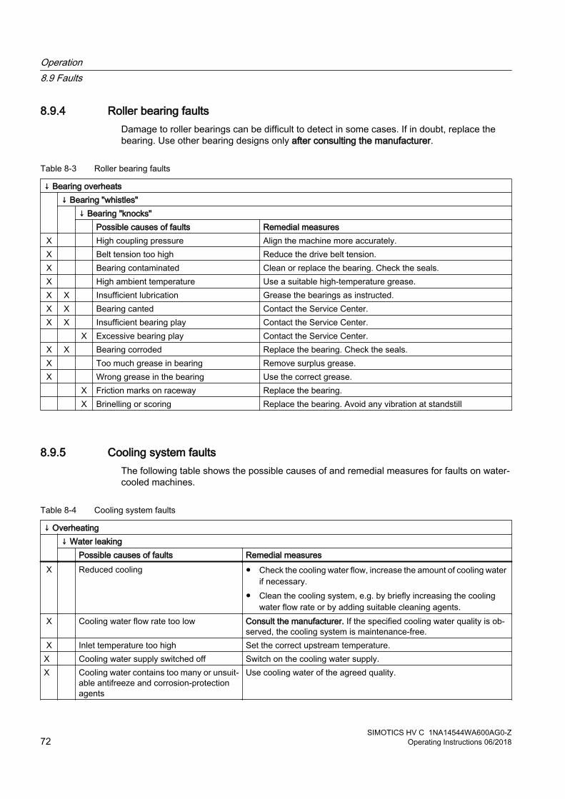
8.9.4 Roller bearing faultsDamage to roller bearings can be difficult to detect in some cases. If in doubt, replace the bearing. Use other bearing designs only after consulting the manufacturer.
Table 8-3 Roller bearing faults
↓ Bearing overheats ↓ Bearing "whistles"
↓ Bearing "knocks" Possible causes of faults Remedial measures
X High coupling pressure Align the machine more accurately.X Belt tension too high Reduce the drive belt tension.X Bearing contaminated Clean or replace the bearing. Check the seals.X High ambient temperature Use a suitable high-temperature grease.X X Insufficient lubrication Grease the bearings as instructed.X X Bearing canted Contact the Service Center.X X Insufficient bearing play Contact the Service Center. X Excessive bearing play Contact the Service Center.X X Bearing corroded Replace the bearing. Check the seals.X Too much grease in bearing Remove surplus grease.X Wrong grease in the bearing Use the correct grease. X Friction marks on raceway Replace the bearing. X Brinelling or scoring Replace the bearing. Avoid any vibration at standstill
8.9.5 Cooling system faultsThe following table shows the possible causes of and remedial measures for faults on water-cooled machines.
Table 8-4 Cooling system faults
↓ Overheating ↓ Water leaking
Possible causes of faults Remedial measuresX Reduced cooling ● Check the cooling water flow, increase the amount of cooling water
if necessary.● Clean the cooling system, e.g. by briefly increasing the cooling
water flow rate or by adding suitable cleaning agents.X Cooling water flow rate too low Consult the manufacturer. If the specified cooling water quality is ob‐
served, the cooling system is maintenance-free.X Inlet temperature too high Set the correct upstream temperature.
X Cooling water supply switched off Switch on the cooling water supply.X Cooling water contains too many or unsuit‐
able antifreeze and corrosion-protection agents
Use cooling water of the agreed quality.
Operation8.9 Faults
SIMOTICS HV C 1NA14544WA600AG0-Z72 Operating Instructions 06/2018
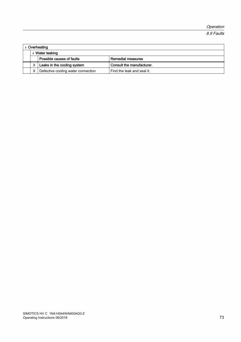
↓ Overheating ↓ Water leaking
Possible causes of faults Remedial measures X Leaks in the cooling system Consult the manufacturer. X Defective cooling water connection Find the leak and seal it.
Operation8.9 Faults
SIMOTICS HV C 1NA14544WA600AG0-ZOperating Instructions 06/2018 73

Operation8.9 Faults
SIMOTICS HV C 1NA14544WA600AG0-Z74 Operating Instructions 06/2018

Maintenance 99.1 Safety instructions for maintenance
Observe the following when carrying out any work on the machine:
● Comply with the general safety instructions (Page 13)
● Comply with the applicable national and sector-specific regulations at the place of installation
● When using the machine within the European Union, comply with the specifications laid down in EN 50110‑1 regarding safe operation of electrical equipment.
Through careful and regular maintenance, inspections, and overhauls you can detect faults at an early stage and resolve them. This means that you can avoid consequential damage.
Operating conditions and characteristics can vary widely. For this reason, only general maintenance intervals can be specified here. Maintenance intervals should therefore be scheduled to suit the local conditions (dirt, starting frequency, load, etc.).
Note
Please contact the service center (Page 99), if you require support with service, maintenance or repair.
9.2 Inspection and maintenance
9.2.1 Safety instructions
WARNING
Rotating and live parts
Electric machines contain live and rotating parts. Fatal or serious injuries and substantial material damage can occur if maintenance work is performed on the machine when it is not stopped or not de-energized.● Perform maintenance work on the machine only when it is stopped. The only operation
permissible while the machine is rotating is regreasing the rolling bearings.● When performing maintenance work, comply with the five safety rules (Page 13).
SIMOTICS HV C 1NA14544WA600AG0-ZOperating Instructions 06/2018 75

WARNING
Machine damage
If the machine is not maintained it can suffer damage. This can cause faults which can result in eventual or immediate death, serious injury or material damage.
Perform regular maintenance on the machine.
CAUTION
Dust disturbances when working with compressed air
When cleaning with compressed air, dust, metal chips, or cleaning agents can be whirled up. Injuries can result.
When cleaning using compressed air, make sure you use suitable extraction equipment and wear protective equipment (safety goggles, protective suit, etc.).
NOTICE
Damage to insulation
If metal swarf enters the winding head when cleaning with compressed air, this can damage the insulation. Clearance and creepage distances can be undershot. This may cause damage to the machine extending to total failure.
When cleaning with compressed air, ensure there is adequate extraction.
NOTICE
Machine damage caused by foreign bodies
Foreign bodies such as dirt, tools or loose components, such as screws etc., can be left by accident inside the machine after maintenance is performed. These can cause short circuits, reduce the performance of the cooling system or increase noise in operation. They can also damage the machine.● When carrying out maintenance work, make sure that no foreign bodies are left in or on
the machine.● Securely attach all loose parts again once you have completed the maintenance
procedures.● Carefully remove any dirt.
Note
Operating conditions and characteristics can vary widely. For this reason, only general intervals for inspection and maintenance measures can be specified here.
9.2.2 Inspections in the event of faultsNatural disasters or unusual operating conditions, such as overloading or short circuit, are faults that overload the machine electrically or mechanically.
Maintenance9.2 Inspection and maintenance
SIMOTICS HV C 1NA14544WA600AG0-Z76 Operating Instructions 06/2018

Immediately perform an inspection after such faults.
9.2.3 First service after installation or repair● Check after approx. 500 operating hours, but after not more than one year:
Check When the motor is running
At stand‐still
The electrical parameters are maintained. X The permissible bearing temperatures are not exceeded. X The smooth running characteristics and machine running noise have not deteriorated.
X
The foundation has no cracks or indentations. (*) X X
(*) You can perform these checks while the motor is at standstill or, if required, while running.
● Further checks may be required if so specified in operating instructions of components (Page 105) or in accordance with the plant-specific conditions.
● If you find any deviations during the inspection, you must rectify them immediately. They may otherwise damage the motor.
Maintenance9.2 Inspection and maintenance
SIMOTICS HV C 1NA14544WA600AG0-ZOperating Instructions 06/2018 77

9.2.4 General inspection● Check that the installation conditions are observed. Perform the following checks after
approx. 16 000 operating hours or at the latest after two years:
Checking When the motor is running
At stand‐still
The electrical parameters are maintained X The permissible bearing temperatures are not exceeded X The smooth running characteristics and machine running noise have not deteriorated
X
The foundation has no cracks or indentations. (*) X XThe machine is aligned within the permissible tolerance ranges. XAll the fixing bolts/screws for the mechanical and electrical connections have been securely tightened
X
All the potential connections, grounding connections and shield supports are correctly seated and properly bonded
X
The winding insulation resistances are sufficiently high (Page 34) XAny bearing insulation is fitted as shown on the plates and labels XThe CABLES and insulating parts and components are in good condition and there is no evidence of discoloring
X
Condensation can freely flow away. X
(*) This check can be made at standstill or when running.
● If you detect any deviations during the inspection, you must rectify them immediately. They may otherwise cause damage to the machine.
Checking the cooling system● With the machine stopped, check the condition of the cooling system:
– The cooling system is in good condition.
– The pressure drop between entry and exit has not increased appreciably.
9.2.5 Servicing the water-jacket cooling● During each inspection, check whether a pool of water has collected under the machine.
Identify the cause: This can be condensation or a leak in the cooling system.
● Check any leakage water electrodes. If necessary, contact your Service Center (Page 99).
9.2.6 Assessing the rolling bearingsTo assess the rolling bearings, it is generally not necessary to dismantle the machines. The motor only has to be dismantled if the bearings are to be replaced.
Maintenance9.2 Inspection and maintenance
SIMOTICS HV C 1NA14544WA600AG0-Z78 Operating Instructions 06/2018

The state of a rolling bearing can be assessed by analyzing the bearing vibration. The measured values provide an indication and can be assessed by specialists. In this case, please contact the Service Center.
See alsoService and Support (Page 99)
9.2.7 Regreasing intervals and types of grease for operating roller bearingsThe specified grease data applies to the data specified on the rating plate and for high-quality grease in accordance with the specifications in these operating instructions. Because these greases exceed significantly the requirements according to DIN 51825 and ISO 6743‑9, they permit the specified relubrication intervals.
Initial lubricationThe grease specified on the lubricant plate is selected according to the operating conditions known at the time of ordering and should be used for initial lubrication.
Grease selection criteriaHigh quality ISO‑L‑X BDEA3 lubricating grease according to ISO 6743-9 and K3K‑20 lubricating grease according to DIN 51825 with lithium soap as a thickener and an upper service temperature of at least +130° C / +266° F are permissible for standard applications without special requirements.
When selecting the lubricating grease, ensure that the technical data of the grease is suitable for the application.
The lubricating grease must satisfy the criteria listed in the table below and must match the operating conditions. If different special lubricating greases are stated on the lubricant plate, then different criteria apply.
Table 9-1 Criteria for selecting roller bearing greases
Criteria Standard Property, characteristic value UnitType of base oil - Mineral oil -Thickener - Lithium -Consistency in accordance with NLGI class
DIN 51818 ● "3" for vertical and horizontal types of construction
● "2" alternatively for horizontal type of construction with reduced lubrication interval
-
Operating temperature range - At least -20° C ... +130° C °CDropping point DIN ISO 2176 At least +180° C °CBasic oil viscosity DIN 51562-1 ● Approx. 100 mm²/s at 40 °C
● Approx. 10 mm²/s at 100 °Cmm²/s
Maintenance9.2 Inspection and maintenance
SIMOTICS HV C 1NA14544WA600AG0-ZOperating Instructions 06/2018 79
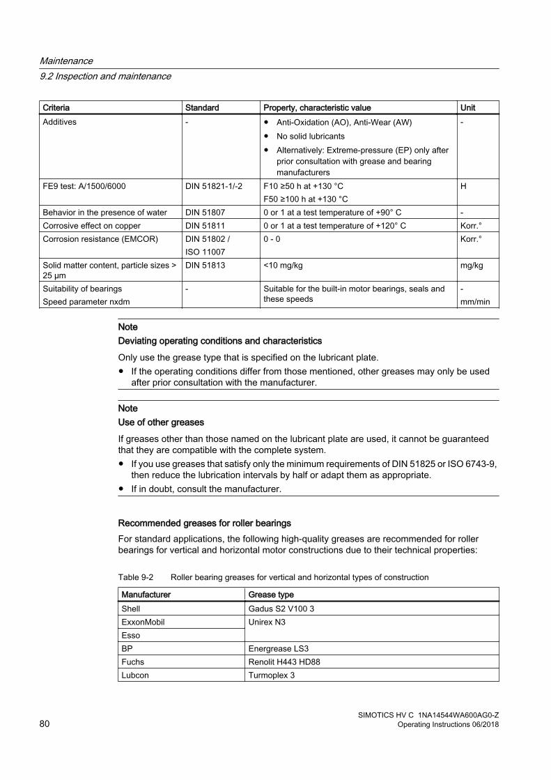
Criteria Standard Property, characteristic value UnitAdditives - ● Anti-Oxidation (AO), Anti-Wear (AW)
● No solid lubricants● Alternatively: Extreme-pressure (EP) only after
prior consultation with grease and bearing manufacturers
-
FE9 test: A/1500/6000 DIN 51821-1/-2 F10 ≥50 h at +130 °CF50 ≥100 h at +130 °C
H
Behavior in the presence of water DIN 51807 0 or 1 at a test temperature of +90° C -Corrosive effect on copper DIN 51811 0 or 1 at a test temperature of +120° C Korr.°Corrosion resistance (EMCOR) DIN 51802 /
ISO 110070 - 0 Korr.°
Solid matter content, particle sizes > 25 µm
DIN 51813 <10 mg/kg mg/kg
Suitability of bearingsSpeed parameter nxdm
- Suitable for the built-in motor bearings, seals and these speeds
-mm/min
NoteDeviating operating conditions and characteristics
Only use the grease type that is specified on the lubricant plate.● If the operating conditions differ from those mentioned, other greases may only be used
after prior consultation with the manufacturer.
NoteUse of other greases
If greases other than those named on the lubricant plate are used, it cannot be guaranteed that they are compatible with the complete system. ● If you use greases that satisfy only the minimum requirements of DIN 51825 or ISO 6743-9,
then reduce the lubrication intervals by half or adapt them as appropriate. ● If in doubt, consult the manufacturer.
Recommended greases for roller bearingsFor standard applications, the following high-quality greases are recommended for roller bearings for vertical and horizontal motor constructions due to their technical properties:
Table 9-2 Roller bearing greases for vertical and horizontal types of construction
Manufacturer Grease typeShell Gadus S2 V100 3ExxonMobil Unirex N3EssoBP Energrease LS3Fuchs Renolit H443 HD88Lubcon Turmoplex 3
Maintenance9.2 Inspection and maintenance
SIMOTICS HV C 1NA14544WA600AG0-Z80 Operating Instructions 06/2018

Manufacturer Grease typeAddinol LM 3 EPFAG Arcanol Multi 3
For motors of horizontal construction you can alternatively use greases with NLGI class 2. However, this reduces the lubrication interval by 20%.
Table 9-3 Alternative greases with NLGI class 2 for motors of horizontal construction
Manufacturer Grease typeShell Gadus S2 V100 2ExxonMobil
Unirex N2EssoBP Energrease LS2Castrol Longtime PD2Lubcon Turmogrease L 802 EP plusShell Retinax LX2FAG Arcanol Multi 2
NOTICE
Diminished lubrication properties by mixing greases
The lubrication properties will be impaired if you mix different greases. This can result in material damage.● Avoid mixing greases. Only the manufacturer can provide a guarantee for the miscibility
of particular greases.
Lubrication dataRegreasing data are stated on the lubricant plate of the machine:
● Regreasing intervals in operating hours
● Regreasing amount in grams
● Grease type
Regrease the roller bearing at the latest every 12 months irrespective of the actual number of operating hours.
NOTICE
Damage to roller bearings
The regreasing intervals for roller bearings are different from the servicing intervals for the machine. The roller bearings may be damaged if the relubrication intervals are not adhered to. ● Pay attention to the instructions on the lubricant plate.
Maintenance9.2 Inspection and maintenance
SIMOTICS HV C 1NA14544WA600AG0-ZOperating Instructions 06/2018 81

Grease replacement intervalsThe grease replacement intervals in these operating instructions or the regreasing intervals indicated on the plate apply to the following conditions:
● Normal load
● Operation at speeds in accordance with rating plate
● Low-vibration operation
● Neutral ambient air
● High-quality roller bearing greases
In the case of unfavorable operating conditions, reduce the relubrication intervals after prior consultation with the manufacturer.
Regreasing roller bearings Pay attention to the instructions on the lubricant plate.
1. Rotate the shaft when regreasing, so that the new grease can be distributed throughout the bearing. Motors that are operated with converters: Regrease the bearings at a low to medium speed (nmin = 250 rpm, nmax = 3600 rpm) to ensure an even distribution of grease.
WARNING
Rotating components
The shaft must rotate to allow the grease to be distributed. This can result in death, serious injury or material damage.● When regreasing, pay attention to all rotating components.
2. Clean the grease nipple before regreasing. Gradually press in an appropriate type and amount of grease, as stamped on the lubricant plate and specified in these operating instructions.The roller bearing temperature rises sharply at first, then drops to the normal value again when the excess grease is displaced out of the bearing.
3. The used grease collects outside each bearing in a spent grease chamber.
Lubricating roller bearings prior to commissioningWhen properly stored prior to commissioning for a longer period of time, normally the grease in the bearings does not deteriorate within two years. Please note the information regarding long-term storage.
When commissioning, the bearings must be relubricated with twice the amount of lubricating grease. When doing this, the shaft must rotate so that the grease is replaced in the bearings.
9.2.8 Removing spent greaseIf the specifications on the lubricant plate are observed, the spent grease chamber will provide capacity for a calculated service life of at least 40 000 operating hours, approx. five years. When the spent grease chamber is full, the spent grease must be removed prior to
Maintenance9.2 Inspection and maintenance
SIMOTICS HV C 1NA14544WA600AG0-Z82 Operating Instructions 06/2018

relubrication. This is indicated by the fact that during relubrication, oil or grease escapes at the bearing cover.
● To remove the spent grease, loosen the outer bearing cap.
NOTICE
Removing spent grease
If the spent grease is not removed, then the roller bearings become too hot and can seize up as the grease distribution mechanism is disturbed.
WARNING
Working on the locating bearing
If the motor is in a vertical position, the rotor can fall out while work is being performed on the locating bearing. This can result in death, serious injury or material damage.
Support or reduce the load on the rotor when carrying out work with the machine in a vertical position.
9.2.9 Maintaining terminal boxes
RequirementThe machine is de-energized.
Checking the terminal box● Terminal boxes must be regularly checked for tightness, undamaged insulation, and tight
terminal connections.
● If dust or humidity have infiltrated the terminal box, this should be cleaned and dried (particularly the insulators).Check all the seals and sealing surfaces and address the cause of the leakiness.
● Check the insulators, connectors and cable connections in the terminal box.
● Replace any damaged components.
WARNING
Short-circuit hazard
Short-circuits can occur as a result of damaged components. This can result in death, serious injury or material damage.
Replace damaged components.
Maintenance9.2 Inspection and maintenance
SIMOTICS HV C 1NA14544WA600AG0-ZOperating Instructions 06/2018 83

9.2.10 Measuring the insulation resistance during the course of maintenance workMeasuring the insulation resistance and polarization index (PI) provides information on the condition of the machine. It is therefore important to check the insulation resistance and the polarization index at the following times:
● Before starting up a machine for the first time
● After an extended period in storage or downtime
● Within the scope of maintenance work
The following information is provided regarding the state of the winding insulation:
● Is the winding head insulation conductively contaminated?
● Has the winding insulation absorbed moisture?
As such, you can determine whether the machine needs commissioning or any necessary measures such as cleaning and/or drying the winding:
● Can the machine be put into operation?
● Must the windings be cleaned or dried?
Detailed information on testing and the limit values can be found here:
"Testing the insulation resistance and polarization index" (Page 35)
9.2.11 Touch up any damaged paintworkIf the paint is damaged, it must be repaired in order to protect the unit against corrosion.
NotePaint system
Contact the Service Center (Page 99) before you repair any damage to paint. They will provide you with more information about the correct paint system and methods of repairing paint damage.
9.3 Corrective Maintenance
9.3.1 Safety instructions for repair work
Observe the following when carrying out any work on the machine:
● Comply with the general safety instructions (Page 13)
● Comply with the applicable national and sector-specific regulations.
● When using the machine within the European Union, comply with the specifications laid down in EN 50110‑1 regarding safe operation of electrical equipment.
Maintenance9.3 Corrective Maintenance
SIMOTICS HV C 1NA14544WA600AG0-Z84 Operating Instructions 06/2018

If the motor has to be transported, please observe the information and instructions in the chapter "Transport (Page 24)".
9.3.2 Prepare servicing work● The drawings and parts lists do not contain any detailed information about the type and
dimensions of fixing elements and components. For this reason, you should establish this information when dismantling them and make a note of it for the purpose of reassembly.
● Document the type, dimensions and arrangement of the parts so that you will be able to reassemble the machine to its original state.
● Use suitable tools to disassemble the machine.
● Take measures to prevent parts from dropping down before you dismantle them, e.g. by replacing fastening elements with extra-long screws, threaded bolts or similar. This ensures that the part is supported after it is pulled off.
● The centerings in the shaft extensions have reset threads. Use lifting gear which is suitable for the rotor weight and direction of loading.
Danger when a rotor fallsEyebolts in accordance with DIN 580 are unsuitable for suspending the rotor. The rotor can fall off. This can result in death, serious injury or material damage.
● Use lifting gear which is suitable for the rotor weight and direction of loading.
Machine damage caused by improper repair workImproper servicing work can damage the machine. This can cause damages and/or faults which can result in eventual or immediate death, serious injury, or property damage.
● Properly assemble or disassemble the machine.
● Use only suitable tools and equipment.
● Immediately replace damaged components.
● If necessary, contact the Service Center (Page 99).
9.3.3 Internal fanThe internal fan is located on the rotor inside the machine. If the internal fan is defective or must be replaced, please contact the Service Center (Page 99).
Maintenance9.3 Corrective Maintenance
SIMOTICS HV C 1NA14544WA600AG0-ZOperating Instructions 06/2018 85

9.3.4 Bearings
9.3.4.1 Removing roller bearings
PreparationThe following preparations are required before removing the rolling bearings.
● Bring the motor into a horizontal position.
● Remove the coupling on the drive end or make the shaft extension freely accessible.
● Remove any mounted components and instruments at the DE and NDE:
– Unscrew the grease removal valve, if present.
– Unscrew the relubrication tubing.
– Unscrew the bearing PT100 and the installation tube.
– Unscrew the shock pulse measurement locations with pipe.
● Depending on the particular version, there could also be a sound absorber, air inlet shroud and fan; also remove these.
For a schematic diagram of the respective component layout, see the chapter "Spare parts (Page 91)".
Procedure 1. Remove the bearing mounting components.
– Remove the outer bearing cover if one is being used. Remove the sealing ring (Page 87).If there is a labyrinth sealing ring, then also remove this.
– Ensure that the inner bearing cover is no longer attached to the bearing housing or end shield.
– Support the rotor for the removal of bearing housing or end shield.
– If necessary, remove the bearing housing from the end shield.
– Remove the end shield. Depending on the shaft height, rolling bearing type and design, it is either a bearing head version or a bearing housing version.
– Remove the locking elements from the shaft; depending on the version, either a locking ring or shaft nut.
2. Remove the rolling bearing: Depending on the particular version, together with the grease slinger or without.
Maintenance9.3 Corrective Maintenance
SIMOTICS HV C 1NA14544WA600AG0-Z86 Operating Instructions 06/2018

9.3.4.2 Remove V ring for roller bearing sealDepending on the particular version, there is a V ring. The V ring must be replaced if unusual amounts of grease escape the roller bearing or the V ring is visibly damaged.
Figure 9-1 Remove the V ring
1. Mark the components so that they can be correctly assembled.
2. Remove the V ring ① with the bearing cap – or by using a suitable tool from the shaft.
Removing the protective ring for IP56 degree of protectionThe V ring for the outer bearing seal is fitted with a protective ring ② for degree of protection IP56. The protective ring does not have to be removed for disassembling the bearing bush.
● Remove the protective ring together with the V ring and the outer bearing cover or end shield from the shaft.
See alsoFitting V ring for roller bearing seal (Page 87)
9.3.4.3 Fitting V ring for roller bearing seal
RequirementThe roller bearing is already fitted.
Maintenance9.3 Corrective Maintenance
SIMOTICS HV C 1NA14544WA600AG0-ZOperating Instructions 06/2018 87

Install the V ring1. Grease the axial sealing surface. The shaft seating remains ungreased.
① V ring② Mounting aid washer③ Protective ring
Figure 9-2 Install the V ring
2. Push the V ring ① onto the shaft using an assembly disk ②.The V ring is in the correct axial position when the face surface is flush with the outer edge of the V ring.
Install the protective ring for IP56 degree of protectionFor degree of protection IP56, the V ring for the outer bearing seal is fitted with a sheet steel protective ring ③ in the bearing cover.
1. Push the protective ring onto the shaft.
2. Verify that the ring is sufficiently pretensioned. Replace the protective ring, if necessary.
3. Position the protective ring so that one of the longitudinal grooves meets the corresponding water separation groove at the bottom in the bearing cover flange or end shield.
9.3.4.4 Installing felt rings for the inner bearing sealDepending on the particular version, the motor is equipped with a felt ring in the inner bearing cover. The felt ring prevents dust and grease from entering the interior of the machine.
Procedure● Before installing new felt rings in the bearing cover, soak them in hot oil (approximately
80°C), such as DIN 51517‑C100 lubricating oil.
● Place the felt ring into its notch on the bearing cap and push the bearing cap onto the shaft.
Maintenance9.3 Corrective Maintenance
SIMOTICS HV C 1NA14544WA600AG0-Z88 Operating Instructions 06/2018
9.3.5 Seal the motorExtreme caution and attention to cleanliness are vital to installation.
● Clean all bare joints between parts such as housings, bearing shields and bearing bushes etc., and remove old sealant material.
● Smear bare joints between parts with non-hardening, permanently flexible sealant, such as "Hylomar M". Follow the manufacturer's application and safety instructions when doing this.
● Check all sealing elements, such as those on the terminal boxes, for elasticity, aging or damage, and renew them if they are no longer effective.
Maintenance9.3 Corrective Maintenance
SIMOTICS HV C 1NA14544WA600AG0-ZOperating Instructions 06/2018 89

Maintenance9.3 Corrective Maintenance
SIMOTICS HV C 1NA14544WA600AG0-Z90 Operating Instructions 06/2018

Spare parts 1010.1 Ordering data
When ordering spare parts, in addition to the precise designation of the spare part, specify the motor type and the serial number of the motor. Ensure that the spare part designation matches the designation in the spare part lists and add the associated part number.
Example
● Bearing shield, drive end (Part 5.00)
● Machine type 1NA1
● Serial number 1525190020001
The machine type and the serial number are indicated on the rating plate and in the technical data, and are also embossed on the drive end of the shaft.
Note
The graphical representations in this chapter show schematic diagrams of the basic versions. They are used for spare parts definitions. The supplied version may differ in details from these representations.
You can use commercially available, standard components, but ensure that they have the same construction type, dimensions, strength class etc.
10.2 Ordering spare parts via the InternetYou can use "Spares on Web" to determine the order numbers for motor spare parts quickly and easily.
Spares on Web (https://www.sow.siemens.com/).
See alsoGuide for Spares on Web (http://support.automation.siemens.com/WW/news/en/25248626)
SIMOTICS HV C 1NA14544WA600AG0-ZOperating Instructions 06/2018 91

Terminal boxIf several terminal boxes are mounted on the machine, please also indicate the type designation of the terminal box in addition to details of part designation and part number according to the legend, as well as type and serial number of the motor when ordering spare parts.
Example● Terminal box type
● Terminal box cover (part 20.30 )
● Serial number of the motor
● Machine type
Rolling-contact bearingsWhen ordering roller bearings, in addition to the bearing identification code, the supplementary specifying code is also necessary for the bearing version. Both of these codes are stamped on the lubricant plate and specified in the motor documentation, or can also be taken from the installed bearings.
Spare parts10.2 Ordering spare parts via the Internet
SIMOTICS HV C 1NA14544WA600AG0-Z92 Operating Instructions 06/2018
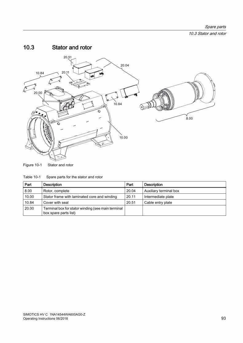
10.3 Stator and rotor
Figure 10-1 Stator and rotor
Table 10-1 Spare parts for the stator and rotor
Part Description Part Description8.00 Rotor, complete 20.04 Auxiliary terminal box10.00 Stator frame with laminated core and winding 20.11 Intermediate plate10.84 Cover with seal 20.51 Cable entry plate20.00 Terminal box for stator winding (see main terminal
box spare parts list)
Spare parts10.3 Stator and rotor
SIMOTICS HV C 1NA14544WA600AG0-ZOperating Instructions 06/2018 93

10.4 Rolling-contact bearings, non-drive end
Figure 10-2 Roller bearings, NDE
Table 10-2 Spare parts for roller bearings, NDE
Part Description Part Description4.00 Roller bearing cartridge (floating bearing) 4.40 Deep-groove ball bearing4.10 V ring 4.45 Compression spring4.16 Labyrinth ring (optional) 4.50 Inner bearing cover4.20 Outer bearing cover 4.81 Nut 4.30 Locking ring 4.82 Grease tube4.35 Grease slinger 6.00 Bearing shield
Spare parts10.4 Rolling-contact bearings, non-drive end
SIMOTICS HV C 1NA14544WA600AG0-Z94 Operating Instructions 06/2018

Disposal 11Protecting the environment and preserving its resources are corporate goals of the highest priority for us. Our worldwide environmental management system to ISO 14001 ensures compliance with legislation and sets high standards in this regard. Environmentally friendly design, technical safety and health protection are always firm goals even at the product development stage.
Recommendations for the environmentally friendly disposal of the machine and its components are given in the following section. Be sure to comply with local disposal regulations.
Country-specific legislationWhen disposing of the machine or of waste that is created during the individual phases of its life cycle, please observe the statutory requirements applicable in the country of use.
11.1 RoHS - restricting the use of certain hazardous substancesIn compliance with RoHS ("Restriction of certain Hazardous Substances" ) we replace substances that are damaging to the environment by those that are not based on state-of-the-art technology. In doing so, safety in operation and handling will take priority at all times.
11.2 Preparing for disassemblyDisassembly of the machine must be carried out and/or supervised by qualified personnel with appropriate expert knowledge.
1. Contact a certified waste disposal organization in your vicinity. Clarify what is expected in terms of the quality of dismantling the machine and provision of the components.
2. Follow the five safety rules (Page 13).
3. Disconnect all electrical connections and remove all cables.
4. Remove all liquids such as oil and cooling liquids. Collect the liquids separately and dispose of them in a professional manner.
5. Detach the machine fixings.
6. Transport the machine to a suitable location for disassembly.
SIMOTICS HV C 1NA14544WA600AG0-ZOperating Instructions 06/2018 95

11.3 Dismantling the machineDismantle the machine using the general procedures commonly used in mechanical engineering.
WARNING
Machine parts can fall
The machine is made up of heavy parts. These parts are liable to fall during dismantling. This can result in death, serious injury or material damage. ● Before you release any machine parts, secure them so that they cannot fall.
11.4 Disposal of components
Components The machines consist mainly of steel and various proportions of copper and aluminum. Metals are generally considered to be unlimitedly recyclable.
Sort the components for recycling according to whether they are:
● Iron and steel
● Aluminum
● Non-ferrous metal, e.g. windingsThe winding insulation is incinerated during copper recycling.
● Insulating materials
● Cables and wires
● Electronic waste
Process materials and chemicals Sort the process materials and chemicals for recycling according to whether they are for example:
● Oil
● Grease
● Cleaning substances and solvents
● Paint residues
● Anti-corrosion agent
● Coolant additives such as inhibitors, antifreeze or biocides
Dispose of the separated components according to local regulations or via a specialist disposal company. The same applies for cloths and cleaning substances which have been used while working on the machine.
Disposal11.3 Dismantling the machine
SIMOTICS HV C 1NA14544WA600AG0-Z96 Operating Instructions 06/2018

Packaging material● If necessary, contact a suitable specialist disposal company.
● Wooden packaging for sea transport consists of impregnated wood. Observe the local regulations.
● The foil used for water-proof packaging is an aluminum composite foil. It can be recycled thermally. Dirty foil must be disposed of via waste incineration.
Disposal11.4 Disposal of components
SIMOTICS HV C 1NA14544WA600AG0-ZOperating Instructions 06/2018 97

Disposal11.4 Disposal of components
SIMOTICS HV C 1NA14544WA600AG0-Z98 Operating Instructions 06/2018

Service and Support ATechnical questions or additional information
If you have any technical questions or require additional information, please contact Technical Support (https://support.industry.siemens.com/cs/ww/en/sc/2090).Please have the following data ready:● Type● Serial numberYou can find this data on the rating plate.
Contact person
If you wish to request on-site service or order spare parts, please contact your local office. This office will contact the responsible service center on your behalf. You can find your contact person in the relevant contact data‐base:www.siemens.com/yourcontact (www.siemens.com/yourcontact)
Siemens Support for on the move
You can obtain optimum support anywhere you go using the "Siemens In‐dustry Online Support” app. The app is available for Apple iOS, Android and Windows Phone.
SIMOTICS HV C 1NA14544WA600AG0-ZOperating Instructions 06/2018 99

Service and Support
SIMOTICS HV C 1NA14544WA600AG0-Z100 Operating Instructions 06/2018
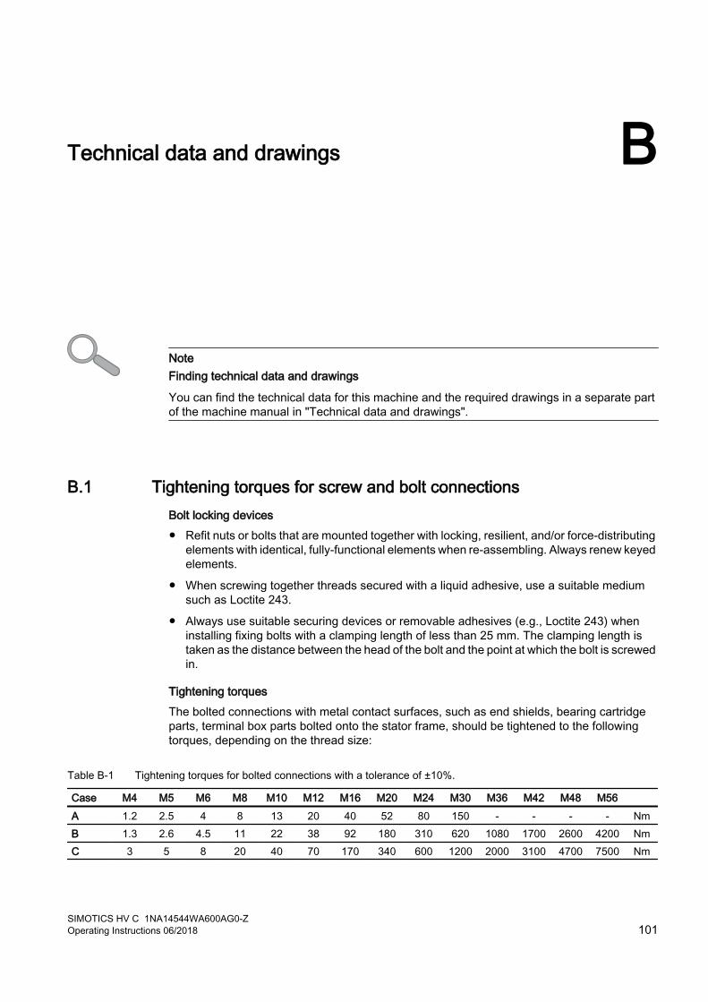
Technical data and drawings B
NoteFinding technical data and drawings
You can find the technical data for this machine and the required drawings in a separate part of the machine manual in "Technical data and drawings".
B.1 Tightening torques for screw and bolt connectionsBolt locking devices ● Refit nuts or bolts that are mounted together with locking, resilient, and/or force-distributing
elements with identical, fully-functional elements when re-assembling. Always renew keyed elements.
● When screwing together threads secured with a liquid adhesive, use a suitable medium such as Loctite 243.
● Always use suitable securing devices or removable adhesives (e.g., Loctite 243) when installing fixing bolts with a clamping length of less than 25 mm. The clamping length is taken as the distance between the head of the bolt and the point at which the bolt is screwed in.
Tightening torques The bolted connections with metal contact surfaces, such as end shields, bearing cartridge parts, terminal box parts bolted onto the stator frame, should be tightened to the following torques, depending on the thread size:
Table B-1 Tightening torques for bolted connections with a tolerance of ±10%.
Case M4 M5 M6 M8 M10 M12 M16 M20 M24 M30 M36 M42 M48 M56 A 1.2 2.5 4 8 13 20 40 52 80 150 - - - - NmB 1.3 2.6 4.5 11 22 38 92 180 310 620 1080 1700 2600 4200 NmC 3 5 8 20 40 70 170 340 600 1200 2000 3100 4700 7500 Nm
SIMOTICS HV C 1NA14544WA600AG0-ZOperating Instructions 06/2018 101
ApplicationsThe above-mentioned tightening torques apply for the following applications:
● Case AApplies to electrical connections in which the permissible torque is normally limited by the bolt materials and/or the current carrying capacity of the insulators, with the exception of the busbar connections in case B.
● Case BApplies to bolts screwed into components made from materials with lower property class (e. g. aluminum) and to bolts with property class 8.8 according to ISO 898-1.
● Case CApplies to bolts with property class 8.8, A4-70 or A4-80 according to ISO 898-1, however only to bolts screwed into components made from materials with higher property class, e.g. cast iron, steel or cast steel.
NoteNon-standard tightening torques
Different tightening torques for electrical connections and bolted connections for parts with flat seals or insulating parts are specified in the relevant sections and drawings.
Technical data and drawingsB.1 Tightening torques for screw and bolt connections
SIMOTICS HV C 1NA14544WA600AG0-Z102 Operating Instructions 06/2018

Quality documents C
NoteFinding quality documents
You can find all quality verifications relating to the machine type such as declarations on the machine's conformity with directives or specifications in Appendix "Quality documents" of the machine manual.
You should also file the documents that will only be handed over to you at a later time due to the process required.
You can find general quality documents here:https://support.industry.siemens.com/cs/ww/de/ps/24701/cert (https://support.industry.siemens.com/cs/ww/en/ps/24701/cert)
SIMOTICS HV C 1NA14544WA600AG0-ZOperating Instructions 06/2018 103

Quality documents
SIMOTICS HV C 1NA14544WA600AG0-Z104 Operating Instructions 06/2018

Additional documents D
NoteFinding additional documents
The documentation for components from other manufacturers that are installed in the machine can be found in the separate part of the machine manual in "Additional documents".
Operating instructions of Siemens components, such as temperature transducer SITRANS TR200/TR300 etc. can be downloaded from the Siemens Industry Online Support Portal.
See alsoSitrans in the Service & Support portal (http://support.automation.siemens.com/WW/view/en/26102748)
SIMOTICS HV C 1NA14544WA600AG0-ZOperating Instructions 06/2018 105

Additional documents
SIMOTICS HV C 1NA14544WA600AG0-Z106 Operating Instructions 06/2018

Index
55 safety rules, 13
AAir gap torques, 23Aligning, 45
Prerequisites, 39Aluminum conductors, 56Anti-corrosion agent
Removing, 43Anti-freeze protection, 68Applications, 19Assembly
Sealing, 89V ring, 87
Axial forces at the shaft extension, 48Axial gap, 47
BBalance quality, 39Bearing covers, 86Bearing seizure damage, 28Bolt locking device, 101
CCenter of gravity, 27, 42Checks to be carried out prior to commissioning, 59Clockwise, 55Condensate, 44Connecting, 49Connecting cables
Selection of, 51, 57Cooling system
Faults, 72Cooling water specification, 21Cooling water supply, 60Correct usage, 20Corrosion protection, 31, 68Counter-clockwise, 55
DDamage during transportation, 25Degree of protection
Derating, 45Delivery, 25Direction of rotation, 55Disassembly
Disposal, 95Internal fan, 85Machine, 85Rolling bearings, 86
DisposalChemicals, 96Components, 96
EElectrical faults, 70Electromagnetic compatibility, 16Electromagnetic fields, 17Emergency off, 67Emitted interference, 17End shield, 86ESD guidelines, 16
Ffaults
Mechanical, 71Faults
Cooling system, 72Electric, 70Inspection, 70, 77Roller bearings, 72
Faults in operation, 66Feather key, 41Felt ring, 88Filling, 49Fixing, 51Flammable substances, 15Foundation forces, 46Foundation surfaces, 38Frequency fluctuation, 22
SIMOTICS HV C 1NA14544WA600AG0-ZOperating Instructions 06/2018 107
GGeneral inspection, 78Grounding conductor
Connecting, 54Cross section, 53
HHazardous substances, 15Hearing damage, 15High-voltage motor
Switching, 24, 63Hot surfaces, 15
IInspection
Faults, 70, 77Installation
Initial inspection, 77Installing the protective ring, 88Insulation resistance, 34, 61, 69, 84
measure, 35Interference immunity, 17Internal fan, 85
LLeakage water, 78Lifting eyebolt, 26, 27, 41, 42Long-term storage, 30
MMachine
Aligning to the driven machine, 47Mounting, 46setting down, 44
Machine designIEC, 19
Machinery Directive, 13Maintenance
Maintenance intervals, 75Mechanical faults, 71Minimum air clearances, 56More information, 99Mounting-foot hole dimensions, 38
NNoise emissions, 15Noise protection measures, 22
OOn-site service, 99Operating mode, 21Output element, 40Overspeed, 21Overvoltage, 63
PPaint finish, 20Paint system, 84Paintwork damage, 84Polarization index, 34, 37, 61, 69, 84Positioning, 47Precision alignment, 47Pressure relief device, 57Property class, 46Protective ring, 87
QQualified personnel, 14
RRadial forces at the shaft extension, 48Rated voltage, 56Rating plate, 20Re-commissioning, 69Regreasing, 67, 82Removing spent grease, 83Repair
Initial inspection, 77Residual risks, 21Restriction of certain Hazardous Substances, 95Risk of explosion, 19RoHS, 95Roller bearings
faults, 72Greasing, 61
Rolling bearingsInspection, 78
Index
SIMOTICS HV C 1NA14544WA600AG0-Z108 Operating Instructions 06/2018
Rolling-contact bearingReplacement, 92
Rotating parts, 15Rotor, 20
SSafety instructions
Flammable substances, 15Hazardous substances, 15Hot surfaces, 15Live parts, 14Maintenance work, 75Rotating parts, 15
Sealing, 56Selection of bolts, 46Shaft assembly, 23Spare parts, 99
Roller bearings, NDE, 94Stator and rotor, 93Terminal box, 92
Spare parts ordering, 91Spares on Web, 91Spent grease chamber, 83Stator winding
Temperature monitoring, 58Stoppages, 67
Roller bearings, 68Storage, 29Storage location, 29Supplementary devices, 20Switching on, 62, 67Switching overvoltages, 24, 60System resonances, 23
TTechnical Support, 99Temperature monitoring
Stator winding, 58Terminal box, 53
close, 57Maintaining, 83Rotating, 53
Terminal marking, 52Test run, 62Thermal protection, 24Tightening torques, 51
Bolted connection, 101Cable lug, 54Ground terminals, 54
Torsional loads, 23Transporting, 27, 42Type of balancing, 39
VV ring, 86, 87Vibration values, 23, 63Voltage fluctuations, 22
WWater connection, 49Water cooling
Inspection, 78Leakage water, 78
Water drip loop, 52
Index
SIMOTICS HV C 1NA14544WA600AG0-ZOperating Instructions 06/2018 109

Index
SIMOTICS HV C 1NA14544WA600AG0-Z110 Operating Instructions 06/2018


Further Information
www.siemens.com/drives
Siemens AGProcess Industries and DrivesPostfach 48 4890026 NÜRNBERGGERMANY