
Simens simatic s7 400 cpu
150
Preface, Contents Structure of a CPU 41x 1 Memory Concept and Startup Scenarios 2 Cycle and Reaction Times of the S7-400 3 Technical Specifications 4 Index Edition 12/2002 A5E00165965-01 Automation System S7-400 CPU Specifications Reference Manual SIMATIC This manual is part of the documentation package with the order number 6ES7398-8AA03-8BA0
-
Upload
ashok-kumar-barla -
Category
Technology
-
view
127 -
download
2
description
SIEMENS SIMATIC S7 400 CPU
Transcript of Simens simatic s7 400 cpu

Preface, Contents
Structure of a CPU 41x1
Memory Concept and Startup Scenarios
2
Cycle and Reaction Times of the S7-400
3
Technical Specifications4
Index
Edition 12/2002A5E00165965-01
Automation System S7-400CPU Specifications
Reference Manual
SIMATIC
This manual is part of the documentationpackage with the order number6ES7398-8AA03-8BA0

Index-2Automation System S7-400
A5E00165965-01
!Danger
indicates that death, severe personal injury or substantial property damage will result if proper precautionsare not taken.
!Warning
indicates that death, severe personal injury or substantial property damage can result if properprecautions are not taken.
!Caution
indicates that minor personal injury can result if proper precautions are not taken.
Caution
indicates that property damage can result if proper precautions are not taken.
Notice
draws your attention to particularly important information on the product, handling the product, or to aparticular part of the documentation.
Qualified PersonnelOnly qualified personnel should be allowed to install and work on this equipment. Qualified persons aredefined as persons who are authorized to commission, to ground and to tag circuits, equipment, andsystems in accordance with established safety practices and standards.
Correct UsageNote the following:
!Warning
This device and its components may only be used for the applications described in the catalog or thetechnical description, and only in connection with devices or components from other manufacturers whichhave been approved or recommended by Siemens.
This product can only function correctly and safely if it is transported, stored, set up, and installedcorrectly, and operated and maintained as recommended.
TrademarksSIMATIC, SIMATIC HMI and SIMATIC NET are registered trademarks of SIEMENS AG.
Third parties using for their own purposes any other names in this document which refer to trademarksmight infringe upon the rights of the trademark owners.
Safety GuidelinesThis manual contains notices intended to ensure personal safety, as well as to protect the products andconnected equipment against damage. These notices are highlighted by the symbols shown below andgraded according to severity by the following texts:
We have checked the contents of this manual for agreementwith the hardware and software described. Since deviationscannot be precluded entirely, we cannot guarantee fullagreement. However, the data in this manual are reviewedregularly and any necessary corrections included insubsequent editions. Suggestions for improvement arewelcomed.
Disclaim of LiabilityCopyright � Siemens AG 2002 All rights reserved
The reproduction, transmission or use of this document or itscontents is not permitted without express written authority.Offenders will be liable for damages. All rights, including rightscreated by patent grant or registration of a utility model ordesign, are reserved.
Siemens AGBereich Automation and DrivesGeschaeftsgebiet Industrial Automation SystemsPostfach 4848, D- 90327 Nuernberg
Siemens AG 2002Technical data subject to change.
Siemens Aktiengesellschaft A5E000165965-01
iiiAutomation System S7-400 CPU SpecificationsA5E00165965-01
Preface
Purpose of the Manual
The manual contains reference information on operator actions, descriptions offunctions and technical specifications of the central processing units, power supplymodules and interface modules of the S7-400.
How to configure, assemble and wire these modules (and other) in an S7-400system is described in the installation manuals for each system.
Required Basic Knowledge
You will need general knowledge of automation to understand this manual.
Target Group
This manual is aimed at people with the required qualifications to commission,operate and maintain the products described.
Scope of this Manual
The manual applies to the S7-400 automation system.
Changes Since the Previous Version
This manual describes S7 CPUs with firmware version 3.1.
Certification
The SIMATIC S7-400 product range has the following certificates:
• Underwriters Laboratories, Inc.: UL 508 (Industrial Control Equipment)
• Canadian Standards Association: CSA C22.2 Number 142, tested (ProcessControl Equipment)
• Factory Mutual Research: Approval Standard Class Number 3611.
You can find details on the certificates and approvals in section 1.1, Standards andCertificates, of the “Module Specifications” reference manual.

Preface
ivAutomation System S7-400 CPU Specifications
A5E00165965-01
CE Labeling
The SIMATIC S7-400 product range complies with the requirements and protectionobjectives of the following EU directives:
• EC low voltage directive 73/23/EEC
• EC electromagnetic compatibility directive 89/336/EEC
C-Tick Mark
The SIMATIC S7-400 product range complies with the requirements of the AS/NZS 2064 standard (Australia and New Zealand).
Standards
The SIMATIC S7-400 product range complies with the requirements and criteria ofthe IEC 61131-2.
Place of this Documentation in the Information Environment
This manual is part of the documentation package for S7-400, M7-400.
System Documentation Package
S7-400/M7-400 • S7-400, M7-400 Programmable Controller; Hardware and Installation
• S7-400, M7-400 Programmable Controllers; Module Specifications
• Automation System S7-400; CPU Data
• S7-400 Instruction List
Navigating
The manual offers the following access aids to make it easy for you to find specificinformation quickly:
• At the start of the manual you will find a complete table of contents and a list ofthe diagrams and tables that appear in the manual.
• An overview of the contents of each section is provided in the left column oneach page of each chapter.
• You will find a glossary in the appendix at the end of the manual. The glossarycontains definitions of the main technical terms used in the manual.
• At the end of the manual you will find a comprehensive index which gives yourapid access to the information you need.

Preface
vAutomation System S7-400 CPU SpecificationsA5E00165965-01
Note
In order to program and commission an S7-400 you requireSTEP 7 V52 as well as the following manuals or manual packages:
Manual/Manual Package
Chapter Overview
Standard Softwarefor S7 and M7
STEP 7 BasicInformation
• Installing and starting up STEP 7 on a programming device / PC
• Working with STEP 7 with the following contents:
Managing projects and files
Configuring and assigning parameters to the S7-400 configuration
Assigning symbolic names for user programs
Creating and testing a user program in STL/LAD
Creating data blocks
Configuring the communication between two or more CPUs
Loading, storing and deleting user programs in the CPU / programming device
Monitoring and controlling user programs
Monitoring and controlling the CPU
• Guide for efficiently implementing the programming task with the programmingdevice / PC and STEP 7
• How the CPUs work (for example, memory concept, access to inputs andoutputs, addressing, blocks, data management)
• Description of STEP 7 data management
• Using data types of STEP 7
• Using linear and structured programming
• Using block call instructions
• Using the debug and diagnostic functions of the CPUs in the user program (forexample, error OBs, status word)
STEP 7 ReferenceInformation
Statement List (STL)for S7-300 andS7-400
Ladder Logic (LAD)
• Basic procedure for working with STL, LAD, or FBD (for example, structure ofSTL, LAD, or FBD, number formats, syntax)
• Description of all instructions in STEP 7 (with program examples)
• Description of the various addressing methods in STEP 7 (with examples)
• Description of all functions integrated in the CPUs
• Description of the internal registers in the CPUfor S7-300 andS7-400
Function BlockDiagram (FBD) forS7-300 and S7-400
System andStandard Functions
Description of the internal registers in the CPU
• Description of all system functions integrated in the CPUs
• Description of all organization blocks integrated in the CPUs
Manual
PG 7xx
• Description of the programming device hardware
• Connecting a programming device to various devices
• Starting up a programming device

Preface
viAutomation System S7-400 CPU Specifications
A5E00165965-01
Recycling and Disposal
The S7-400 is low in contaminants and can therefore be recycled. To recycle anddispose of your old device in an environment-friendly manner, please contact adisposal company certified for disposal of electronic waste.
Further Support
If you have any technical questions, please get in touch with your Siemensrepresentative or agent responsible.
http://www.siemens.com/automation/partner
Training Centers
We offer a number of courses to help you become familiar with the SIMATIC S7programmable logic controller. Please contact your regional training center or ourcentral training center in D 90327 Nuremberg, Germany for details:
Phone: +49 (911) 895-3200.
Internet: http://www.sitrain.com

Preface
viiAutomation System S7-400 CPU SpecificationsA5E00165965-01
A&D Technical Support
Available 24 hours a day, worldwide:
Johnson City
Nuremberg
Bejiing
Technical Support
Worldwide (Nuremberg)
Technical Support
Local time: 0:00 to 24:00 / 365 days
Phone: +49 (0) 180 5050-222
Fax: +49 (0) 180 5050-223
E-Mail: [email protected]
GMT: +1:00
Europe / Africa (Nuremberg)
Authorization
Local time: Mo. - Fr. 8:00 amto 5:00 pm
Phone: +49 (0) 180 5050–222
Fax: +49 (0) 180 5050-223
E-Mail: [email protected]
GMT: +1:00
United States (Johnson City)
Technical Support andAuthorizationLocal time: Mo. - Fr. 8:00 amto 5:00 pm
Phone: +1 (0) 423 262 2522
Fax: +1 (0) 423 262 22 89
E-mail: [email protected]
GMT: –5:00
Asia / Australia (Bejiing)
Technical Support andAuthorizationLocal time: Mo. - Fr. 8:00 amto 5:00 pm
Phone: +86 10 64 75 75 75
Fax: +86 10 64 74 74 74
E-mail: [email protected]
GMT: +8:00
The languages of the SIMATIC Hotlines and the authorization hotline are generally German and English.

Preface
viiiAutomation System S7-400 CPU Specifications
A5E00165965-01
Service & Support in the Internet
In addition to our documentation, we also offer you the benefit of all our knowledgeon the Internet.
http://www.siemens.com/automation/service&support
There you will find:
• A newsletter with all the latest information on your products
• Knowledge Manager to locate the documentation you require
• A forum in which users and specialists throughout the world exchange theirexperiences
• Your local contact person for Automation & Drives using our contact database
• Information about our on-site service, repairs, spare parts and much more isavailable under the heading “Service”.

ixAutomation System S7-400 CPU SpecificationsA5E00165965-01
Contents
1 Structure of a CPU 41x 1-1. . . . . . . . . . . . . . . . . . . . . . . . . . . . . . . . . . . . . . . . . . . . . . . . . .
1.1 Controls and Indicators of the CPUs 1-2. . . . . . . . . . . . . . . . . . . . . . . . . . . . . . .
1.2 Monitoring Functions of the CPU 1-9. . . . . . . . . . . . . . . . . . . . . . . . . . . . . . . . . .
1.3 Status and Error LEDs 1-11. . . . . . . . . . . . . . . . . . . . . . . . . . . . . . . . . . . . . . . . . . .
1.4 Mode Selector 1-14. . . . . . . . . . . . . . . . . . . . . . . . . . . . . . . . . . . . . . . . . . . . . . . . . .
1.5 Design and Function of Memory Cards 1-18. . . . . . . . . . . . . . . . . . . . . . . . . . . . .
1.6 Multipoint Interface (MPI) 1-22. . . . . . . . . . . . . . . . . . . . . . . . . . . . . . . . . . . . . . . . .
1.7 PROFIBUS DP Interface 1-23. . . . . . . . . . . . . . . . . . . . . . . . . . . . . . . . . . . . . . . . .
1.8 Overview of the Parameters for the S7-400 CPUs 1-24. . . . . . . . . . . . . . . . . . .
1.9 Multicomputing 1-26. . . . . . . . . . . . . . . . . . . . . . . . . . . . . . . . . . . . . . . . . . . . . . . . . . 1.9.1 Peculiarities 1-28. . . . . . . . . . . . . . . . . . . . . . . . . . . . . . . . . . . . . . . . . . . . . . . . . . . . 1.9.2 Multicomputing Interrupt 1-29. . . . . . . . . . . . . . . . . . . . . . . . . . . . . . . . . . . . . . . . . . 1.9.3 Configuring and Programming Multicomputing Operation 1-29. . . . . . . . . . . . .
1.10 Modifications to the System During Operation 1-30. . . . . . . . . . . . . . . . . . . . . . .
1.11 CPU 41x as DP Master/DP Slave 1-34. . . . . . . . . . . . . . . . . . . . . . . . . . . . . . . . . 1.11.1 DP Address Areas of the CPUs 41x 1-35. . . . . . . . . . . . . . . . . . . . . . . . . . . . . . . 1.11.2 CPU 41x as DP Master 1-36. . . . . . . . . . . . . . . . . . . . . . . . . . . . . . . . . . . . . . . . . . 1.11.3 Isochrone Updating of the Process Image Partition 1-40. . . . . . . . . . . . . . . . . . 1.11.4 Diagnostics of the CPU 41x as DP Master 1-41. . . . . . . . . . . . . . . . . . . . . . . . . . 1.11.5 CPU 41x as DP Slave 1-46. . . . . . . . . . . . . . . . . . . . . . . . . . . . . . . . . . . . . . . . . . . 1.11.6 Diagnostics of the CPU 41x as DP Slave 1-51. . . . . . . . . . . . . . . . . . . . . . . . . . . 1.11.7 CPU 41x as DP slave: Station States 1 to 3 1-57. . . . . . . . . . . . . . . . . . . . . . . . .
1.12 Direct Communication 1-64. . . . . . . . . . . . . . . . . . . . . . . . . . . . . . . . . . . . . . . . . . . 1.12.1 Principle of Direct Data 1-64. . . . . . . . . . . . . . . . . . . . . . . . . . . . . . . . . . . . . . . . . . . 1.12.2 Diagnostics in Direct Communication 1-66. . . . . . . . . . . . . . . . . . . . . . . . . . . . . . .
1.13 Consistent Data 1-68. . . . . . . . . . . . . . . . . . . . . . . . . . . . . . . . . . . . . . . . . . . . . . . . . 1.13.1 Consistency for Communication Blocks and Functions 1-69. . . . . . . . . . . . . . . 1.13.2 Access to the Working Memory of the CPU 1-69. . . . . . . . . . . . . . . . . . . . . . . . . 1.13.3 Read from and Writing to a DP Standard Slave Consistently 1-69. . . . . . . . . . 1.13.4 Writing Data Consistently to a
DP Standard Slave Using SFC 15 “DPWR_DAT” 1-70. . . . . . . . . . . . . . . . . . . . 1.13.5 Consistent Data Access without the Use of SFC 14 or SFC 15 1-71. . . . . . . .
2 Memory Concept and Startup Scenarios 2-1. . . . . . . . . . . . . . . . . . . . . . . . . . . . . . . . .
2.1 Overview of the Memory Concept of S7-400 CPUs 2-2. . . . . . . . . . . . . . . . . .
2.2 Overview of the Startup Scenarios for S7-400-CPUs 2-5. . . . . . . . . . . . . . . . .

Contents
xAutomation System S7-400 CPU Specifications
A5E00165965-01
3 Cycle and Reaction Times of the S7-400 3-1. . . . . . . . . . . . . . . . . . . . . . . . . . . . . . . . .
3.1 Cycle Time 3-2. . . . . . . . . . . . . . . . . . . . . . . . . . . . . . . . . . . . . . . . . . . . . . . . . . . . .
3.2 Cycle Time Calculation 3-4. . . . . . . . . . . . . . . . . . . . . . . . . . . . . . . . . . . . . . . . . . .
3.3 Different Cycle Times 3-8. . . . . . . . . . . . . . . . . . . . . . . . . . . . . . . . . . . . . . . . . . . .
3.4 Communication Load 3-10. . . . . . . . . . . . . . . . . . . . . . . . . . . . . . . . . . . . . . . . . . . .
3.5 Reaction Time 3-13. . . . . . . . . . . . . . . . . . . . . . . . . . . . . . . . . . . . . . . . . . . . . . . . . .
3.6 How Cycle and Reaction Times Are Calculated 3-18. . . . . . . . . . . . . . . . . . . . . .
3.7 Examples of Calculating the Cycle Time and Reaction Time 3-19. . . . . . . . . . .
3.8 Interrupt Reaction Time 3-22. . . . . . . . . . . . . . . . . . . . . . . . . . . . . . . . . . . . . . . . . .
3.9 Example of Calculating the Interrupt Reaction Time 3-24. . . . . . . . . . . . . . . . . .
3.10 Reproducibility of Time-Delay and Watchdog Interrupts 3-25. . . . . . . . . . . . . . .
4 Technical Specifications 4-1. . . . . . . . . . . . . . . . . . . . . . . . . . . . . . . . . . . . . . . . . . . . . . . .
4.1 Technical Specifications of the CPU 412-1; (6ES7412-1XF03-0AB0) 4-2. . . . . . . . . . . . . . . . . . . . . . . . . . . . . . . . . . . . . . . . .
4.2 Technical Specifications of the CPU 412-2; (6ES7412-2XG00-0AB0) 4-6. . . . . . . . . . . . . . . . . . . . . . . . . . . . . . . . . . . . . . . . .
4.3 Technical Specifications of the CPU 414-2; (6ES7414-2XG03-0AB0) 4-10. . . . . . . . . . . . . . . . . . . . . . . . . . . . . . . . . . . . . . . . .
4.4 Technical Specifications of the CPU 414-3; (6ES7414-3XJ00-0AB0) 4-14. . . . . . . . . . . . . . . . . . . . . . . . . . . . . . . . . . . . . . . . . .
4.5 Technical Specifications of the CPU 416-2; (6ES7416-2XK02-0AB0, 6ES7416-2FK02-0AB0) 4-18. . . . . . . . . . . . . . . . . . . .
4.6 Technical Specifications of the CPU 416-3; (6ES7416-3XL00-0AB0) 4-22. . . . . . . . . . . . . . . . . . . . . . . . . . . . . . . . . . . . . . . . . .
4.7 Technical Specifications of the CPU 417-4; (6ES7417-4XL00-0AB0) 4-26. . . . . . . . . . . . . . . . . . . . . . . . . . . . . . . . . . . . . . . . . .
4.8 Technical Specifications of the Memory Cards 4-30. . . . . . . . . . . . . . . . . . . . . . .
Index Index-1. . . . . . . . . . . . . . . . . . . . . . . . . . . . . . . . . . . . . . . . . . . . . . . . . . . . . . .

Contents
xiAutomation System S7-400 CPU SpecificationsA5E00165965-01
Figures1-1 Layout of the Controls and Indicators of the CPU 412-1 1-2. . . . . . . . . . . . . . 1-2 Layout of the Controls and Indicators of the CPU 41x-2 1-3. . . . . . . . . . . . . . . 1-3 Layout of the Controls and Indicators of the CPU 41x-3 1-4. . . . . . . . . . . . . . . 1-4 Layout of the Controls and Indicators of the CPU 417-4 1-5. . . . . . . . . . . . . . 1-5 Positions of the Mode Selector 1-14. . . . . . . . . . . . . . . . . . . . . . . . . . . . . . . . . . . . 1-6 Structure of the Memory Card 1-18. . . . . . . . . . . . . . . . . . . . . . . . . . . . . . . . . . . . . 1-7 Multicomputing Example 1-27. . . . . . . . . . . . . . . . . . . . . . . . . . . . . . . . . . . . . . . . . 1-8 Overview: Architecture enabling modification
of a system during operation 1-30. . . . . . . . . . . . . . . . . . . . . . . . . . . . . . . . . . . . . . 1-9 Diagnostics with CPU 41x 1-43. . . . . . . . . . . . . . . . . . . . . . . . . . . . . . . . . . . . . . . . 1-10 Diagnostic Addresses for the DP Master and DP Slave 1-44. . . . . . . . . . . . . . . 1-11 Intermediate Memory in the CPU 41x as DP Slave 1-47. . . . . . . . . . . . . . . . . . . 1-12 Diagnostic Addresses for the DP Master and DP Slave 1-54. . . . . . . . . . . . . . . 1-13 Structure of the Slave Diagnosis 1-56. . . . . . . . . . . . . . . . . . . . . . . . . . . . . . . . . . . 1-14 Structure of the Module Diagnosis of the CPU 41x 1-60. . . . . . . . . . . . . . . . . . . 1-15 Structure of the Station Diagnosis 1-61. . . . . . . . . . . . . . . . . . . . . . . . . . . . . . . . . 1-16 Bytes +4 to +7 for Diagnostic and Process Interrupts 1-62. . . . . . . . . . . . . . . . . 1-17 Direct Communication with CPUs 41x 1-65. . . . . . . . . . . . . . . . . . . . . . . . . . . . . . 1-18 Diagnostic Address for the Recipient During Direct Communication 1-66. . . . 3-1 Parts and Composition of the Cycle Time 3-3. . . . . . . . . . . . . . . . . . . . . . . . . . . 3-2 Different Cycle Times 3-8. . . . . . . . . . . . . . . . . . . . . . . . . . . . . . . . . . . . . . . . . . . . 3-3 Minimum Cycle Time 3-9. . . . . . . . . . . . . . . . . . . . . . . . . . . . . . . . . . . . . . . . . . . . 3-4 Formula: Influence of Communication Load 3-10. . . . . . . . . . . . . . . . . . . . . . . . . 3-5 Breakdown of a Time Slice 3-10. . . . . . . . . . . . . . . . . . . . . . . . . . . . . . . . . . . . . . . 3-6 Dependency of the Cycle Time on the Communication Load 3-12. . . . . . . . . . 3-7 DP Cycle Times on the PROFIBUS-DP Network 3-14. . . . . . . . . . . . . . . . . . . . . 3-8 Shortest Reaction Time 3-15. . . . . . . . . . . . . . . . . . . . . . . . . . . . . . . . . . . . . . . . . . 3-9 Longest Reaction Time 3-16. . . . . . . . . . . . . . . . . . . . . . . . . . . . . . . . . . . . . . . . . . . 3-10 Calculating the Interrupt Reaction Time 3-22. . . . . . . . . . . . . . . . . . . . . . . . . . . . .

Contents
xiiAutomation System S7-400 CPU Specifications
A5E00165965-01
Tables1-1 LEDs of the CPUs 1-6. . . . . . . . . . . . . . . . . . . . . . . . . . . . . . . . . . . . . . . . . . . . . . . 1-2 Positions of the Mode Selector 1-15. . . . . . . . . . . . . . . . . . . . . . . . . . . . . . . . . . . 1-3 Protection Levels of a S7-400 CPU 1-16. . . . . . . . . . . . . . . . . . . . . . . . . . . . . . . . 1-4 Types of Memory Cards 1-19. . . . . . . . . . . . . . . . . . . . . . . . . . . . . . . . . . . . . . . . . 1-5 CPUs 41x (MPI/DP Interface as PROFIBUS DP) 1-35. . . . . . . . . . . . . . . . . . . 1-6 CPUs 41x (MPI/DP Interface and DP Module as PROFIBUS DP) 1-35. . . . . . 1-7 Meaning of the BUSF LED of the CPU 41x as DP Master 1-41. . . . . . . . . . . . . 1-8 Reading Out the Diagnosis with STEP 7 1-42. . . . . . . . . . . . . . . . . . . . . . . . . . . 1-9 Event Detection of the CPUs 41x as DP Master 1-45. . . . . . . . . . . . . . . . . . . . . 1-10 Configuration Example for the Address Areas
of the Intermediate Memory 1-48. . . . . . . . . . . . . . . . . . . . . . . . . . . . . . . . . . . . . . 1-11 Meaning of the BUSF LEDs of the CPU 41x as DP Slave 1-51. . . . . . . . . . . . . 1-12 Reading Out the Diagnostic Data with STEP 5
and STEP 7 in the Master System 1-52. . . . . . . . . . . . . . . . . . . . . . . . . . . . . . . . 1-13 Event Detection of the CPUs 41x as DP Slave 1-55. . . . . . . . . . . . . . . . . . . . . . 1-14 Evaluation of RUN-STOP Transitions in the DP Master/DP Slave 1-55. . . . . 1-15 Structure of the Station Status 1 (Byte 0) 1-57. . . . . . . . . . . . . . . . . . . . . . . . . . . 1-16 Structure of Station Status 2 (Byte 1) 1-58. . . . . . . . . . . . . . . . . . . . . . . . . . . . . . 1-17 Structure of Station Status 3 (Byte 2) 1-58. . . . . . . . . . . . . . . . . . . . . . . . . . . . . . 1-18 Structure of the Master PROFIBUS Address (Byte 3) 1-58. . . . . . . . . . . . . . . . 1-19 Structure of the Manufacturer ID (Bytes 4, 5) 1-59. . . . . . . . . . . . . . . . . . . . . . . . 1-20 Event Detection of the CPUs 41x as
Recipient During Direct Communication 1-66. . . . . . . . . . . . . . . . . . . . . . . . . . . . 1-21 Evaluation of the Station Failure in the
Sender During Direct Communication 1-67. . . . . . . . . . . . . . . . . . . . . . . . . . . . . . 2-1 Memory Requirements 2-3. . . . . . . . . . . . . . . . . . . . . . . . . . . . . . . . . . . . . . . . . . 3-1 Cyclic Program Scanning 3-3. . . . . . . . . . . . . . . . . . . . . . . . . . . . . . . . . . . . . . . . . 3-2 Factors that Influence the Cycle Time 3-4. . . . . . . . . . . . . . . . . . . . . . . . . . . . . . 3-3 Portions of the process image transfer time 3-5. . . . . . . . . . . . . . . . . . . . . . . . 3-4 Portions of the process image transfer time, H CPUs 3-6. . . . . . . . . . . . . . . . 3-5 User program processing time for the CPU 41x-4H 3-7. . . . . . . . . . . . . . . . . . 3-6 Operating system scan time at scan cycle checkpoint 3-7. . . . . . . . . . . . . . . . 3-7 Increase in Cycle Time by Nesting Interrupts 3-7. . . . . . . . . . . . . . . . . . . . . . . . 3-8 Reducing the Reaction Time 3-17. . . . . . . . . . . . . . . . . . . . . . . . . . . . . . . . . . . . . . 3-9 Example of Calculating the Reaction Time 3-18. . . . . . . . . . . . . . . . . . . . . . . . . . 3-10 Hardware Interrupt and Diagnostic Interrupt Reaction Times;
Maximum Interrupt Reaction Time Without Communication 3-22. . . . . . . . . . . 3-11 Reproducibility of Time-Delay and Watchdog Interrupts of the CPUs. 3-25. .

1-1Automation System S7-400 CPU SpecificationsA5E00165965-01
Structure of a CPU 41x
Chapter Overview
In Section You Will Find On Page
1.1 Controls and Indicators of the CPUs 1-2
1.2 Monitoring Functions of the CPU 1-9
1.3 Status and Error LEDs 1-11
1.4 Mode selector 1-14
1.5 Design and Function of Memory Cards 1-18
1.6 Multipoint Interface (MPI) 1-22
1.7 PROFIBUS DP interface 1-23
1.8 Overview of the Parameters for the S7-400 CPUs 1-24
1.9 Multicomputing 1-26
1.10 Modifications to the System During Operation 1-30
1.11 CPU 41x as DP Master/DP Slave 1-34
1.12 Direct Communication 1-64
1.13 Consistent data 1-68
1

Structure of a CPU 41x
1-2Automation System S7-400 CPU Specifications
A5E00165965-01
1.1 Controls and Indicators of the CPUs
Controls and Indicators of the CPU 412-1
Mode selector
Slot for the memory card
Incoming supply of external backup voltage
Under cover
LEDs INTF, EXTF, BUS1F,FRCE, RUN, STOP
MPI/PROFIBUS DP interface
BUS1F
CPU 412-1
6ES7412-1XF03-0AB0
Module designation, version, abbre-viated order number and firmwareversion
V3.0.0
Figure 1-1 Layout of the Controls and Indicators of the CPU 412-1
Structure of a CPU 41x
1-3Automation System S7-400 CPU SpecificationsA5E00165965-01
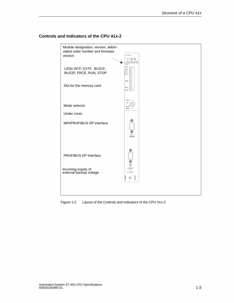
Controls and Indicators of the CPU 41x-2
Mode selector
Slot for the memory card
Incoming supply of
Under cover
LEDs INTF, EXTF, BUS1F,BUS2F, FRCE, RUN, STOP
MPI/PROFIBUS DP interface
PROFIBUS DP interface
BUS1F
BUS2F
CPU 414-2
6ES7414-2XG03-0AB0
Module designation, version, abbre-viated order number and firmwareversion
V3.0.0
external backup voltage
Figure 1-2 Layout of the Controls and Indicators of the CPU 41x-2

Structure of a CPU 41x
1-4Automation System S7-400 CPU Specifications
A5E00165965-01
Controls and Indicators of the CPU 41x-3
Mode selector
Slot for the memory card
Under coverUnder cover
Module slot for in-terface module
LEDs INTF, EXTF, BUS1F,BUS2F, FRCE, RUN, STOP
MPI/PROFIBUS DP interface
PROFIBUS DP interface
LEDsIFM1F
BUS1F
BUS2F
IFM1F
CPU 416-3
6ES7416-3XL00-0AB0
Module designation, version, abbre-viated order number and firmwareversion
V3.0.0
Incoming supply ofexternal backup voltage
Figure 1-3 Layout of the Controls and Indicators of the CPU 41x-3

Structure of a CPU 41x
1-5Automation System S7-400 CPU SpecificationsA5E00165965-01
Controls and Indicators of the CPU 417-4
Mode selector
Slot for the memory card
Under coverUnder cover
Module slot for in-terface module 1
Module slot for in-terface module 2
LEDs INTF, EXTF, BUS1F,BUS2F, FRCE, RUN, STOP
MPI/PROFIBUS DP interface
PROFIBUS DP interface
LEDs IFM1F, IFM2F
BUS1F
BUS2F
IFM1FIFM2F
Under the metal lidon the left-hand side
Interface for memory expansion
Module designation, version, abbre-viated order number and firmwareversion
V3.0.0
Incoming supply ofexternal backup voltage
Figure 1-4 Layout of the Controls and Indicators of the CPU 417-4
LEDs
Table 1-1 gives you an overview of the LEDs on the individual CPUs.
Section 1.2 describes the states and errors indicated by these LEDs.

Structure of a CPU 41x
1-6Automation System S7-400 CPU Specifications
A5E00165965-01
Table 1-1 LEDs of the CPUs
LED Color Meaning In CPU
412-1 412-2414-2416-2
414-3416-3
417-4
INTF red Internal fault x x x x
EXTF red External fault x x x x
FRCE yellow Active force request x x x x
RUN green RUN mode x x x x
STOP yellow STOP mode x x x x
BUS1F red Bus fault at MPI/PROFIBUS DPinterface 1
x x x x
BUS2F red Bus fault at PROFIBUS DP interface 2
– x x x
IFM1F red Error at interface submodule 1 – – x x
IFM2F red Error at interface submodule 2 – – – x
Mode Selector
You can use the mode selector to select the current operating mode of the CPU.The mode selector is a key switch with four switching positions. You can usedifferent protection levels and limit any program changes or startup options (STOPto RUN transition) to a certain group of people.
Section 1.4 describes the functions of the mode selector and the protection levelsof the CPUs.
Slot for Memory Cards
You can insert a memory card in this slot.
There are two types of memory card:
• RAM cards
You can expand the load memory of a CPU with the RAM card.
• FLASH cards
You can use the FLASH card to store your user program and your data so thatthey are failproof (even without a backup battery). You can either program theFLASH card on the programming device or in the CPU. The FLASH card alsoexpands the load memory of the CPU.
You can find a detailed description of the memory cards in Chapter 1.5.

Structure of a CPU 41x
1-7Automation System S7-400 CPU SpecificationsA5E00165965-01
Slot for Interface Modules
You can insert one interface module (IF module) for each CPUs 41x-3 and 41x-4 inthis slot.
Interface for Memory Expansion
CPU 417-4 also features interfaces for memory expansion. These make it possibleto expand the working memory. (See�“S7-400, M7-400 Programmable Controllers,Hardware and Installation” �
MPI/DP interface
You can connect the following devices to the MPI of the CPU, for example:
• Programming devices
• Operation and monitoring devices
• Additional S7-400 or S7-300 controllers (see Section 1.6).
Use the bus connector with an angular outgoing cable (see the Installation manual,Chapter 7)
You can also configure the MPI interface as a DP master and use it as aPROFIBUS DP interface with up to 32 DP slaves.
PROFIBUS DP interface
You can connect the distributed I/O, programming devices/OPs and additionalDP master stations to the PROFIBUS DP interface.
Structure of a CPU 41x
1-8Automation System S7-400 CPU Specifications
A5E00165965-01
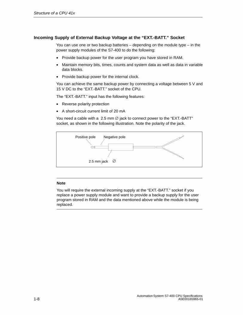
Incoming Supply of External Backup Voltage at the “EXT.-BATT.” Socket
You can use one or two backup batteries – depending on the module type – in thepower supply modules of the S7-400 to do the following:
• Provide backup power for the user program you have stored in RAM.
• Maintain memory bits, times, counts and system data as well as data in variabledata blocks.
• Provide backup power for the internal clock.
You can achieve the same backup power by connecting a voltage between 5 V and15 V DC to the “EXT.-BATT.” socket of the CPU.
The “EXT.-BATT.” input has the following features:
• Reverse polarity protection
• A short-circuit current limit of 20 mA
You need a cable with a 2.5 mm ∅ jack to connect power to the “EXT.-BATT”socket, as shown in the following illustration. Note the polarity of the jack.
Positive pole Negative pole
2.5 mm jack ∅
Note
You will require the external incoming supply at the “EXT.-BATT.” socket if youreplace a power supply module and want to provide a backup supply for the userprogram stored in RAM and the data mentioned above while the module is beingreplaced.
Structure of a CPU 41x
1-9Automation System S7-400 CPU SpecificationsA5E00165965-01
1.2 Monitoring Functions of the CPU
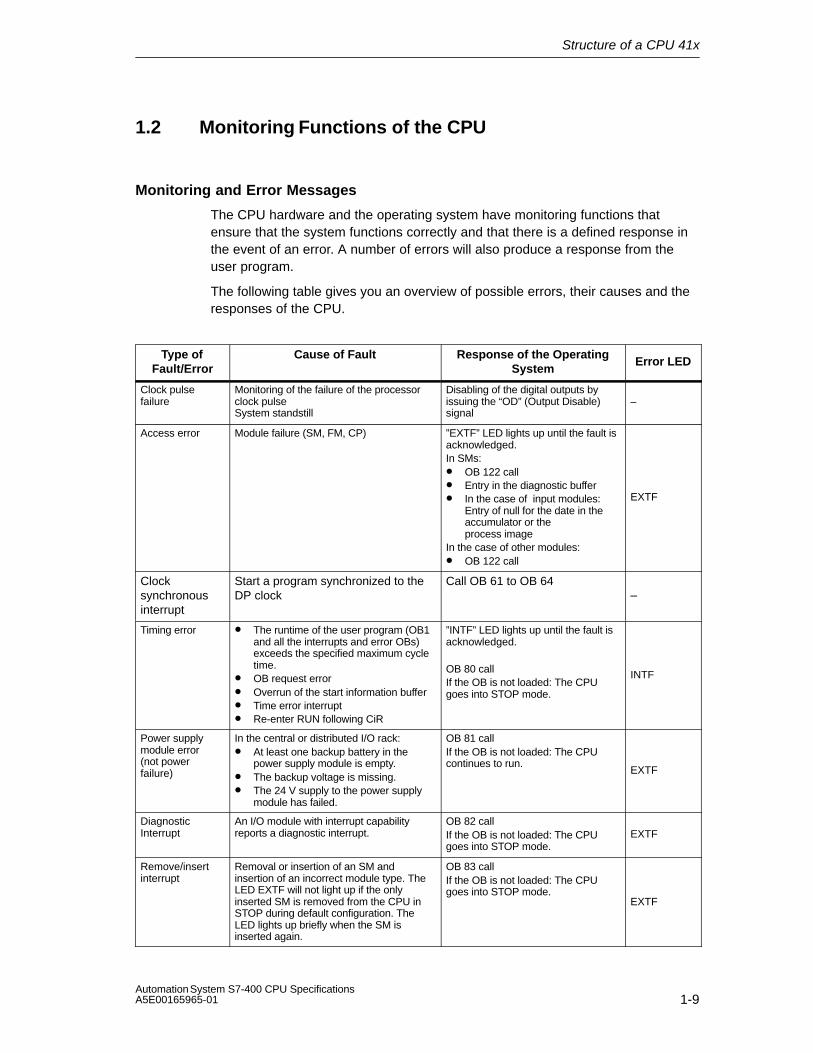
Monitoring and Error Messages
The CPU hardware and the operating system have monitoring functions thatensure that the system functions correctly and that there is a defined response inthe event of an error. A number of errors will also produce a response from theuser program.
The following table gives you an overview of possible errors, their causes and theresponses of the CPU.
Type ofFault/Error
Cause of Fault Response of the OperatingSystem
Error LED
Clock pulsefailure
Monitoring of the failure of the processorclock pulseSystem standstill
Disabling of the digital outputs byissuing the “OD” (Output Disable)signal
–
Access error Module failure (SM, FM, CP) ”EXTF” LED lights up until the fault isacknowledged.In SMs:• OB 122 call• Entry in the diagnostic buffer• In the case of input modules:
Entry of null for the date in theaccumulator or the process image
In the case of other modules:• OB 122 call
EXTF
Clocksynchronousinterrupt
Start a program synchronized to theDP clock
Call OB 61 to OB 64–
Timing error • The runtime of the user program (OB1and all the interrupts and error OBs)exceeds the specified maximum cycletime.
• OB request error• Overrun of the start information buffer• Time error interrupt• Re-enter RUN following CiR
”INTF” LED lights up until the fault isacknowledged.
OB 80 callIf the OB is not loaded: The CPUgoes into STOP mode.
INTF
Power supplymodule error(not powerfailure)
In the central or distributed I/O rack:• At least one backup battery in the
power supply module is empty.• The backup voltage is missing.• The 24 V supply to the power supply
module has failed.
OB 81 callIf the OB is not loaded: The CPUcontinues to run.
EXTF
DiagnosticInterrupt
An I/O module with interrupt capabilityreports a diagnostic interrupt.
OB 82 callIf the OB is not loaded: The CPUgoes into STOP mode.
EXTF
Remove/insertinterrupt
Removal or insertion of an SM andinsertion of an incorrect module type. TheLED EXTF will not light up if the onlyinserted SM is removed from the CPU inSTOP during default configuration. TheLED lights up briefly when the SM isinserted again.
OB 83 callIf the OB is not loaded: The CPUgoes into STOP mode.
EXTF

Structure of a CPU 41x
1-10Automation System S7-400 CPU Specifications
A5E00165965-01
Type ofFault/Error Error LED
Response of the OperatingSystem
Cause of Fault
Priority classerror
• Priority class is called, but thecorresponding OB is not available.
• In the case of an SFB call: Theinstance DB is missing or defective.
OB 85 callIf the OB is not loaded: The CPUgoes into STOP mode.
INTF
• Error during the updating of theprocess image EXTF
Failure of arack/station
• Power failure in an expansion rack• Failure of a DP line• Failure of a coupling line: missing or
defective IM, interrupted line)
OB 86 callIf the OB is not loaded: The CPUgoes into STOP mode. EXTF
Communicationerror
• Status information cannot be entered inDB
• Incorrect frame identifier• Frame length error• Error in the structure of the global data
message• DB access error
OB 87 callIf the OB is not loaded: The CPUgoes into STOP mode.
INTF
Cancelprocessing
• Nesting depth exceeded forsynchronous errors
• Too many nested block calls (Bstack)
• Error allocating local data
Call OB 88If the OB is not loaded: The CPUgoes into STOP mode.
INTF
Programmingerror
Error in the machine code or in the userprogram:• BCD conversion error• Range length error• Range error• Alignment error• Write error• Timer number error• Counter number error• Block number error• Block not loaded
OB 121 callIf the OB is not loaded: The CPUgoes into STOP mode.
INTF
MC7 code error Error in the compiled user program (e.g.impermissible OP code or jump over theend of the block)
CPU goes into STOP mode.Reboot or memory reset required. INTF
Loss of clock Clock was lost either because an OB61 to 64 was not start due to higherpriorities or because additionalasynchronous bus loads suppressedthe bus clock.
Call OB 61..64 at the next pulse.
INTFEXTF
There are also test and information functions available in each CPU that you cancall up with STEP 7.

Structure of a CPU 41x
1-11Automation System S7-400 CPU SpecificationsA5E00165965-01
1.3 Status and Error LEDs
Status LEDs
The two RUN and STOP LEDs on the front panel of a CPU informs you of thecurrently active CPU operating status.
LED Meaning
RUN STOP
H D CPU is in RUN state.
D H CPU is in STOP state. The user program is not processed. Restart andwarm restart/reboot is possible. If the STOP status was triggered by anerror, the error indication (INTF or EXTF) is also set.
B
2 Hz
B
2 Hz
CPU has the status DEFECT. The INTF, EXTF and FRCE LEDs alsoflash.
B
0.5 Hz
H HALT status has been triggered by a test function.
B
2 Hz
H A warm restart/reboot/restart has been triggered. It can take a minute orlonger to execute the warm restart/reboot/restart depending on the lengthof the OB called. If the CPU still does not go into RUN, there might be anerror in the system configuration.
x B
0.5 Hz
Memory reset is requested by the CPU.
x B
2 Hz
Memory reset is running.
D = LED is dark; H = LED lights up; B = LED flashes with the specified frequency;x = LED status is irrelevant
Structure of a CPU 41x
1-12Automation System S7-400 CPU Specifications
A5E00165965-01
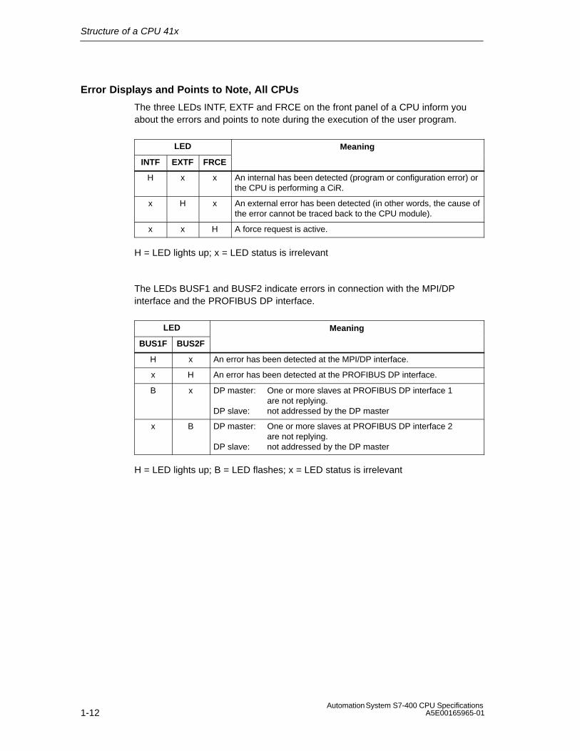
Error Displays and Points to Note, All CPUs
The three LEDs INTF, EXTF and FRCE on the front panel of a CPU inform youabout the errors and points to note during the execution of the user program.
LED Meaning
INTF EXTF FRCE
H x x An internal has been detected (program or configuration error) orthe CPU is performing a CiR.
x H x An external error has been detected (in other words, the cause ofthe error cannot be traced back to the CPU module).
x x H A force request is active.
H = LED lights up; x = LED status is irrelevant
The LEDs BUSF1 and BUSF2 indicate errors in connection with the MPI/DPinterface and the PROFIBUS DP interface.
LED Meaning
BUS1F BUS2F
H x An error has been detected at the MPI/DP interface.
x H An error has been detected at the PROFIBUS DP interface.
B x DP master: One or more slaves at PROFIBUS DP interface 1are not replying.
DP slave: not addressed by the DP master
x B DP master: One or more slaves at PROFIBUS DP interface 2are not replying.
DP slave: not addressed by the DP master
H = LED lights up; B = LED flashes; x = LED status is irrelevant
Structure of a CPU 41x
1-13Automation System S7-400 CPU SpecificationsA5E00165965-01
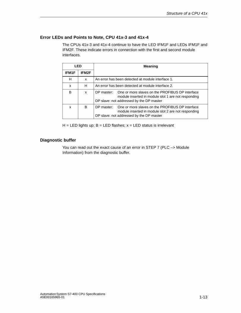
Error LEDs and Points to Note, CPU 41x-3 and 41x-4
The CPUs 41x-3 and 41x-4 continue to have the LED IFM1F and LEDs IFM1F andIFM2F. These indicate errors in connection with the first and second moduleinterfaces.
LED Meaning
IFM1F IFM2F
H x An error has been detected at module interface 1.
x H An error has been detected at module interface 2.
B x DP master: One or more slaves on the PROFIBUS DP interface module inserted in module slot 1 are not responding
DP slave: not addressed by the DP master
x B DP master: One or more slaves on the PROFIBUS DP interface module inserted in module slot 2 are not responding
DP slave: not addressed by the DP master
H = LED lights up; B = LED flashes; x = LED status is irrelevant
Diagnostic buffer
You can read out the exact cause of an error in STEP 7 (PLC –> ModuleInformation) from the diagnostic buffer.
Structure of a CPU 41x
1-14Automation System S7-400 CPU Specifications
A5E00165965-01
1.4 Mode Selector
Function of the Mode Selector
Using the mode selector, you can put the CPU in RUN/RUN-P or STOP mode orreset the memory of the CPU. STEP 7 offers further options for changing themode.
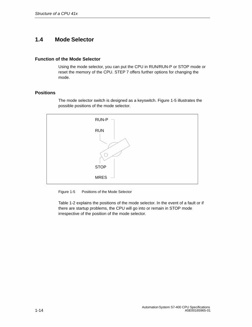
Positions
The mode selector switch is designed as a keyswitch. Figure 1-5 illustrates thepossible positions of the mode selector.
RUN-P
RUN
STOP
MRES
Figure 1-5 Positions of the Mode Selector
Table 1-2 explains the positions of the mode selector. In the event of a fault or ifthere are startup problems, the CPU will go into or remain in STOP modeirrespective of the position of the mode selector.

Structure of a CPU 41x
1-15Automation System S7-400 CPU SpecificationsA5E00165965-01
Table 1-2 Positions of the Mode Selector
Position Explanation
RUN-P If there is no startup problem or error and the CPU can go into RUN, the CPUprocesses the user program or is idle. It is possible to access the I/O. The key cannotbe removed in this position.
Programs can:• Be read out with the programming device from the CPU (CPU programming
device)• Be transferred to the CPU (programming device CPU).
RUN If there is no startup problem or error and the CPU can go into RUN, the CPUprocesses the user program or runs in idle. It is possible to access the I/O. The key canbe removed in this position to ensure that the mode cannot be changed withoutauthorization.
The programming device can read the programs in the CPU (CPU –> PG).
The program in the CPU cannot be changed when the switch is in the RUNposition (see STEP 7)! The protection level can be bypassed using a passwordset in the STEP 7 / Hardware Configuration (STEP 7 V4.02 and above). In otherwords, if you use this password, the program can also be changed when theswitch is in the RUN position.
STOP The CPU does not process the user program. The digital signal modules are disabled.
The key can be removed in this position to ensure that the operating mode cannot bechanged without authorization.
Programs can:• Be read out with the programming device from the CPU (CPU programming device)• Be transferred to the CPU (programming device CPU).
MRES
(Master Reset)
Momentary-contact position of the key switch for the master reset of the CPU and forcold restart (see the following pages).
Protection Levels
A protection level can be defined in the CPUs of the S7-400 that can be used toprotect the programs in the CPU from unauthorized access. You can determinewith the protection level which programming device functions a user can executeon the CPU in question without particular authorization (password). You canexecute all the programming device functions using a password.
Setting the Protection Levels
You can set the protection levels (1 to 3) for a CPU under STEP 7/ConfiguringHardware.
You can remove the protection level set under STEP 7/Configuring Hardware usinga manual reset with the mode selector.
You can also set protection levels 1 and 2 using the mode selector. Table 1-3 liststhe protection levels of a CPU of the S7-400.

Structure of a CPU 41x
1-16Automation System S7-400 CPU Specifications
A5E00165965-01
Table 1-3 Protection Levels of a S7-400 CPU
ProtectionLevel
Function Switch Position
1 • All programming device functions are permitted(default setting).
RUN-P/STOP
2 • It is permissible to load objects from the CPU intoprogramming device. In other words, only readprogramming device functions are permitted.
• Functions for process control, process monitoringand process communication are permitted.
• All information functions are permitted.
RUN
3 • Functions for process control, process monitoringand process communication are permitted.
• All information functions are permitted.
–
If different protection levels are set with the mode selector and with STEP 7, thehigher protection level applies (3 before 2, 2 before 1).
Operating Sequence for Memory Reset
Case A: You want to download a complete, new user program to the CPU.
1. Turn the switch to the STOP position.
Result: The STOP LED lights up.
2. Turn the switch to the MRES setting and keep it at this setting.
Result: The STOP LED is dark for a second, light for a second, dark for asecond and then remains on.
3. Turn the switch back to the STOP setting, then to the MRES setting againwithin the next 3 seconds and back to STOP.
Result: The STOP LED flashes for at least 3 seconds at 2 Hz (memory reset isexecuted) and then lights up permanently
Case B: When the STOP LED flashes slowly at 0.5 Hz, the CPU is requestinga memory reset (system memory reset request, after a memory card hasbeen removed or inserted, for example).
Turn the switch to MRES and back to the STOP position.
Result:The STOP LED flashes for at least 3 seconds at 2 Hz (reset is beingexecuted) and then remains lit.
You can find the complete description of what happens during a memory reset inthe: S7-400, M7-400 Programmable Controllers Installation Manual, Chapter 6.
Cold Restart
The user program is started again following a cold restart. All the data, includingthe retentive data, are deleted.
Structure of a CPU 41x
1-17Automation System S7-400 CPU SpecificationsA5E00165965-01
Restart
Following a restart, the user program resumes at the position at which it wasinterrupted.
If the restart after power-on function (automatic restart) is to work, the S7-400must have a battery backup.
Reboot (Warm Restart)
The user program is started again following a warm restart. The retentive data andthe contents of the data blocks are kept.
Operating Sequence at Warm Restart/Reboot/Restart
1. Turn the switch to the STOP position.
Result: The STOP LED lights up.
2. Turn the switch to the RUN/RUNP setting.
Whether the CPU executes a warm restart/reboot or a restart depends on theparameter assignment for the CPU.
Operating Sequence at Cold Restart
1. Turn the switch to the STOP position.
Result: The STOP LED lights up.
2. Turn the switch to the MRES setting and keep it at this setting.
Result: The STOP LED is dark for a second, light for a second, dark for asecond and then remains on.
3. Turn the switch to the RUN/RUNP setting.

Structure of a CPU 41x
1-18Automation System S7-400 CPU Specifications
A5E00165965-01
1.5 Design and Function of Memory Cards
Order Numbers
The order numbers for memory cards are listed in the technical specifications inChapter 4.
Configuration
The memory card is slightly larger than a credit card and protected by a strongmetal casing. It is plugged into a receptacle at the front of the CPU; the end to beinserted is obvious from the design of the memory card.
Grip
Side elevation
Type plate
Front elevation
Ord
er n
umbe
rN
ame
of th
e M
emor
y C
ard
Figure 1-6 Structure of the Memory Card
Function
The memory card and an integrated memory area on the CPU together form theload memory of the CPU. In operation, the load memory contains the completeuser program including comments, symbols, special additional information thatpermits decompiling of the user program, and all the module parameters (seeChapter 2.1).

Structure of a CPU 41x
1-19Automation System S7-400 CPU SpecificationsA5E00165965-01
What the Memory Card Contains
The following data can be stored in the memory card:
• User program, that is, blocks (OBs, FBs, FCs, DBs) and system data
• Parameters that determine the behavior of the CPU
• Parameters that determine the behavior of the I/O modules.
• As of STEP 7 V5.1 the Project in Their Entirety in Suitable Memory Cards.
Types of Memory Cards for the S7-400
Two types of memory card are used in the S7-400:
• RAM cards
• Flash cards (FEPROM cards)
Note
Non-Siemens memory cards cannot be used in the S7-400.
What Type of Memory Card Should You Use?
Whether you use a RAM card or a Flash card depends on how you intend to usethe memory card.
Table 1-4 Types of Memory Cards
If you ... ...Then
want to store the data in RAM and you wantto modify your program during RUN orRUN-P mode,
use a RAM card
want to store your user programpermanently on the memory card, even withpower removed (without backup or outsidethe CPU),
use a Flash card
Structure of a CPU 41x
1-20Automation System S7-400 CPU Specifications
A5E00165965-01
RAM Card
you use a RAM card, you must plug this into the CPU to load the user program.The user program is loaded with the help of the programming device (PG).
You can load the entire user program or the individual parts such as FBs, FCs,OBs, DBs, or SDBs into the load memory in STOP mode or in RUN-P mode.
If you remove the RAM card from the CPU, the information stored on it is lost. TheRAM card does not have a built-in backup battery.
If the power supply has a functioning backup battery or if an external backupvoltage is supplied to the CPU via the “EXT. BATT.” socket, the contents of theRAM card are retained after switching off the power supply provided the RAM cardremains plugged into the CPU and the CPU remains in the rack.
Flash Card
If you use a Flash card, there are two ways of loading the user program:
• Set the CPU to STOP with the mode selector, plug the Flash card into the CPU,and load the user program with STEP 7 “PLC –> Load User Program to Memory Card”.
• Load the user program into the Flash card in offline mode at the programmingdevice or adapter and then insert the Flash card into the CPU.
You can only load your complete user program with the Flash card. You can loadsmaller program sections into the integrated load memory on the CPU using theprogramming device. In the case of larger program changes, you must alwaysreload the Flash card with the complete user program.
The Flash card does not require voltage to store its contents, that is, theinformation stored on it is retained even when you remove the Flash card from theCPU or if you operate your S7-400 system without backup (without backup batteryin the power supply module or “EXT. BATT.” socket of the CPU).
Which Memory Card Capacity to Use
The capacity of the memory card you use depends on the size of the user programand the additional memory requirement resulting from the use of function modulesor communications modules. See the manuals of these modules for details of theirmemory requirements.
To optimally use the working memory (code and data) your CPU, you shouldexpand the load memory of the CPU with a memory card with at least the samecapacity as the working memory.
Structure of a CPU 41x
1-21Automation System S7-400 CPU SpecificationsA5E00165965-01
Changing the Memory Card
To change the memory card, follow the steps outlined below:
1. Set the CPU to STOP.
2. Remove the plugged in memory card.
Note
If you remove the memory card, the CPU requests a memory reset by flashing theSTOP indicator every three seconds. This sequence cannot be influenced by errorOBs.
3. Insert a “new” memory card.
4. Perform a memory reset on the CPU.

Structure of a CPU 41x
1-22Automation System S7-400 CPU Specifications
A5E00165965-01
1.6 Multipoint Interface (MPI)
Connectable Devices
You can, for example, connect the following nodes to the MPI:
• Programming devices (PG/PC)
• Operation and monitoring devices (OPs and TDs)
• Additional SIMATIC S7 programmable controllers
Some connectable devices take a supply of 24 V from the interface. This voltage isavailable there in non-isolated form.
Programming Device/OP-CPU Communication
A CPU can maintain several simultaneous online connections duringcommunication with programming devices/OPs. By default, one of theseconnections is for a programming device and one is for an OP/operation andmonitoring unit.
For more information about the number of connection resources and the numberOPs that can be connected for each CPU, refer to Chapter 4 TechnicalSpecifications.
Communication and Interrupt Response Times
NoticeThe interrupt reaction times can be delayed by read and write jobs with a highdata volume (approx. 460 byte).
CPU-CPU Communication
There are two types of CPU-CPU communication:
• Data transfer via S7 basic communication
• Data transfer via S7 communication
You can find additional information on this in the “Programming with STEP 7”manual.
Connector
Use only the bus connector with an angular outgoing cable for PROFIBUS DP or aprogramming device cable for connecting devices to the MPI (see Chapter 7 in theInstallation Manual).

Structure of a CPU 41x
1-23Automation System S7-400 CPU SpecificationsA5E00165965-01
Multipoint Interface as DP Interface
You can also configure the MPI interface as a DP interface. To do this, you canreconfigure the MPI interface under STEP 7 in SIMATIC Manager. You can usethis to set up a DP line with a maximum of 32 slaves.
1.7 PROFIBUS DP Interface
Connectable Devices
You can connect any PROFIBUS DP slave that complies with the standard to thePROFIBUS DP interface.
In this case, the CPU is either a DP master or DP slave connected via thePROFIBUS DP field bus to the passive slave stations or other DP masters.
Some connectable devices take a supply of 24 V from the interface. This voltage isavailable there in non-isolated form.
Connector
Use only the bus connector for PROFIBUS DP or PROFIBUS cable for connectingdevices to the PROFIBUS DP interface (see Chapter 7 in the Installation Manual).
Structure of a CPU 41x
1-24Automation System S7-400 CPU Specifications
A5E00165965-01
1.8 Overview of the Parameters for the S7-400 CPUs
Default Values
All the parameters have default settings at delivery. These defaults, which aresuitable for a whole range of standard applications, mean that the S7-400 can beused immediately without the need for further settings.
You can find the CPU-specific default values using “Configuring Hardware” inSTEP 7.
Parameter Blocks
The behavior and properties of the CPU are defined using parameters that arestored in system data blocks. The CPUs have a defined default setting. You canchange this default setting by modifying the parameters in the hardwareconfiguration.
The following list gives you an overview of the configurable system propertiesavailable in the CPUs.
• General properties (e.g. Name of the CPU)
• Startup (e.g. enabling of a restart)
• Clock synchronous interrupts
• Cycle/clock memory (e.g. cycle monitoring time)
• Retentivity (number of memory markers, timers and counters that aremaintained)
• Memory (e.g.local data)
Note: If, for example, you set greater or smaller values than the default valuesfor the process image, the number of diagnostic buffer entries and themaximum number of ALARM-8 blocks (SFB 34 and SFB 35) and blocks for S7communication, the working memory available for the program code and fordata blocks will be reduced or increased by this amount.
• Assignment of interrupts (process interrupts, delay interrupts, asynchronouserror interrupts) to the priority classes
• Time-of-day interrupts (e.g. start, interval duration, priority)
• Watchdog interrupts (e.g. priority, interval duration)
• Diagnostics/clock (e.g. time synchronization)
• Protection levels
Note
16 memory bytes and 8 counter numbers are set to retentive in the defaultsettings, in other words, they are not deleted when the CPU is restarted.
Structure of a CPU 41x
1-25Automation System S7-400 CPU SpecificationsA5E00165965-01
Parameter Assignment Tool
You can set the individual CPU parameters using “Configuring Hardware” inSTEP 7.
NoteIf you make changes to the existing settings of the following parameters, theoperating system carries out initializations like those during cold restart.• Size of the process image of the inputs
• Size of the process image of the inputs
• Size of the local data
• Number of diagnostic buffer inputs
• Communication resources
These initializations are:
– Data blocks are initialized with the load values
– Memory bits, times, counts, inputs and outputs are deleted regardless ofthe retentive settings (0)
– DBs generated via SFC are deleted
– Permanently configured, base communication connections are established
– All the priority classes start from the beginning again
Structure of a CPU 41x
1-26Automation System S7-400 CPU Specifications
A5E00165965-01
1.9 Multicomputing
Chapter Overview
Section Description Page
1.9.1 Peculiarities 1-28
1.9.2 Multicomputing Interrupt 1-29
1.9.3 Configuring and Programming Multicomputing Operation 1-29
What is Multicomputing Operation?
Multicomputing operation is the operation of several (max. 4)multicomputing-capable central processing units at the same time in a central rack(central device) of the S7-400.
The CPUs involved automatically change their modes synchronously. In otherwords, they start up together and change to STOP mode together. The userprogram runs on each CPU irrespective of the user programs in the other CPUs.This makes it possible to execute controller tasks in parallel.
When Do You Use Multicomputing?
It is advantageous to use multicomputing in the following cases:
• If your user program is too large for a single CPU and storage space isbecoming scarce, distribute your program over several CPUs.
• If a certain part of your system is supposed to be processed quickly, removethe relevant program section from the overall program and have it processed bya separate, “quick” CPU.
• If your system consists of several different parts that can be easily separatedfrom one another and can therefore be controlled relatively independently, letCPU1 process system part 1, CPU 2 system part 2 and so on.
Structure of a CPU 41x
1-27Automation System S7-400 CPU SpecificationsA5E00165965-01
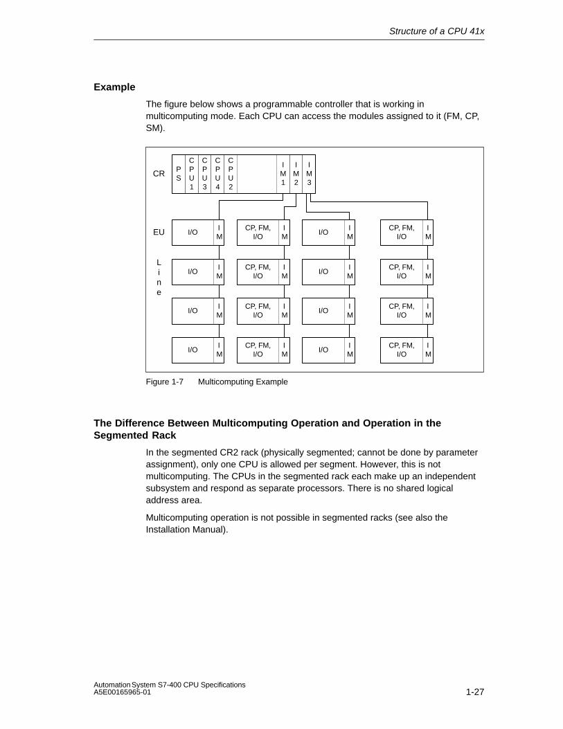
Example
The figure below shows a programmable controller that is working inmulticomputing mode. Each CPU can access the modules assigned to it (FM, CP,SM).
PS
CPU1
CPU3
CPU4
CPU2
IM1
IM2
IM3
IM
I/O
IM
I/O
IM
I/O
IM
I/O
IM
CP, FM,I/O
IM
CP, FM,I/O
IM
CP, FM,I/O
IM
CP, FM,I/O
IM
I/O
IM
I/O
IM
I/O
IM
I/O
IM
CP, FM,I/O
IM
CP, FM,I/O
IM
CP, FM,I/O
IM
CP, FM,I/O
CR
EU
Line
Figure 1-7 Multicomputing Example
The Difference Between Multicomputing Operation and Operation in theSegmented Rack
In the segmented CR2 rack (physically segmented; cannot be done by parameterassignment), only one CPU is allowed per segment. However, this is notmulticomputing. The CPUs in the segmented rack each make up an independentsubsystem and respond as separate processors. There is no shared logicaladdress area.
Multicomputing operation is not possible in segmented racks (see also theInstallation Manual).
Structure of a CPU 41x
1-28Automation System S7-400 CPU Specifications
A5E00165965-01
1.9.1 Peculiarities
Slot Rules
In multicomputing operation, up to four CPUs can be inserted at the same time in acentral controller (CC) in any order.
If you use CPUs that can only handle module start addresses that are divisible by4 (usually CPUs before 10/98), you must keep to this rule for all the configuredCPUs when you assign addresses! The rule applies should you also use CPUsthat allow the bytewise assignment of module start addresses in single-computingoperation.
Bus Connection
The CPUs are connected to one another via the communication bus (K bus). Inother words, if configured appropriately, all the CPUs can be reached by theprogramming device via an MPI interface.
Behavior at Startup and During Operation
At startup, the CPUs involved in multicomputing operation automatically checkwhether they can synchronize with each other. Synchronization is only possible if:
• All the configured CPUs (but only those) are inserted and not defective.
• Correct configuration data (SDBs) have been created and loaded for all theinserted CPUs.
If one of these prerequisites is not met, the event is entered in the diagnostic bufferwith ID 0x49A4. You can find explanations of the event IDs in the referenceinformation for standard and system functions.
When STOP mode is exited, a comparison of the types of startup (COLDRESTART/REBOOT (WARM RESTART/RESTART) is carried out. If their startuptype differs, the CPUs do not go into RUN mode.
Assignment of Addresses and Interrupts
In multicomputing operation, the individual CPUs can each access the modulesthat were allocated to them during configuration with STEP 7. The address area ofa module is always assigned exclusively to a CPU.
Each interrupt-capable module is assigned to a CPU. Interrupts originating fromsuch a module cannot be received by the other CPUs.

Structure of a CPU 41x
1-29Automation System S7-400 CPU SpecificationsA5E00165965-01
Interrupt Processing
The following applies to interrupt processing:
• Process interrupts and diagnostic interrupts are only sent to one CPU.
• When a module fails or is removed or inserted, the interrupt is processed by theCPU that was assigned to the module at parameter assignment with STEP 7.Exception: A module insertion/removal interrupt that starts from a CP reachesall the CPUs even if the CP was assigned to a CPU at configuration withSTEP 7.
• In the event of a rack failure, OB 86 is called on each CPU, including CPUs thatwere not assigned a module in the failed rack.
You can find further information on the OB 86 in the reference information onorganization blocks.
Typical I/O Application Specification
The typical I/O application specification of a programmable controller correspondsin multicomputing operation to the typical application specification of the CPU withthe most resources. The relevant CPU-specific or DP master-specific typicalapplication specifications cannot be exceeded in the individual CPUs.
1.9.2 Multicomputing Interrupt
Using the multicomputing interrupt (OB 60), you can respond synchronously to anevent in multicomputing on the corresponding CPUs. In contrast to the processinterrupts triggered by signal modules, the multicomputing interrupt can be outputonly by CPUs. The multicomputing interrupt is triggered by calling SFC 35“MP_ALM“.
You will find more information in the System Software for S7-300/400, System andStandard Functions manual.
1.9.3 Configuring and Programming Multicomputing Operation
Please refer to the manual Configuring Hardware and Communication Connectionswith STEP 7 V5.2 to find out how to configure and program the CPUs and themodules.

Structure of a CPU 41x
1-30Automation System S7-400 CPU Specifications
A5E00165965-01
1.10 Modifications to the System During Operation
The ability to modify the system during operation using CiR (Configuration in RUN)allows you to make certain changes to the configuration in the RUN mode.Processing is halted for a brief period in order to accomplish this. The upper limit ofthis time period is set to one second by default but can be changed. During thistime, the process inputs retain their most recent value (see the manual, “Modifications to the System During Operation Using CiR”
You can download a free copy of this manual from the Internetaddress:http://www.siemens.com/automation/service&support
You can modify the system during operation using CiR in system segments withdistributed I/O. This requires a configuration as shown in the following illustration.To simplify the example, only one DP master system and one PA master systemare shown. These restrictions do not apply in actual practice.
ÉÉÉÉÉÉÉÉÉÉÉÉÉÉÉÉÉÉÉÉÉÉÉÉÉÉÉÉÉÉ
ModularDP SlaveET200M,ET200SorET200iS
CompactDP Slave
IM 157+DP/PACoupler
PA Slave(field device)
SUBNET: PA Master SystemÉÉÉÉÉÉÉÉÉÉÉÉÉÉÉÉÉÉÉÉÉÉDP Master
MPI/DP interface of a CPU 41x or DP interfaceof a CPU 41x-2 or interface module IF 964-DPor an external DP interface module CP 443-5ext.
PROFIBUS: DP Master System
PA LinkPA Slave(field de-vice)
Figure 1-8 Overview: Architecture enabling modification of a system during operation
Structure of a CPU 41x
1-31Automation System S7-400 CPU SpecificationsA5E00165965-01
Hardware Requirements for Modification of a System During Operation
The following hardware requirement must be fulfilled during the commissioningphase in order to be able to subsequently modify the system during operation:
• An S7-400 standard CPU (CPU 412, CPU 414, CPU 416 or CPU 417),firmware V3.1 or later, or an S7-400-H-CPU (CPU 414-4H or CPU 417-4H) insingle mode. firmware V3.1 or later.
• If you wish to modify the system during operation on a DP master system withan external DP master (CP 443-5 extended), it must have firmware V5.0 orlater.
• If you want to add modules for the ET 200M: Use the IM153-2 version MLFB6ES7 153-2AA03-0XB0 or later or the IM 153-2FO version MLFB 6ES7153-2BB00-0XB0 or later. You will also need to install the ET 200M with activebus elements and with enough free space for the planned expansion. You maynot install the ET 200M as DPV0 slave (using a GSD file).
• If you wish to add entire stations: be sure to include the required busconnectors, repeaters, etc.
• If you wish to add PA slaves (field devices): use IM157 version6ES7157-0AA82-0XA00 or later in the corresponding DP/PA Link.
• Rack CR2 cannot be used.
• The cannot use one or more of the following modules within a station where youwish to modify the system during operation using CiR: CP 441-1, CP 441-2, CP444.
• No multicomputing
• No multimaster configuration
• No use of I-slaves on DP master systems from where you wish to modify thesystem during operation using CiR.
If you have configured a CPU 41x as a I-slave on one of your interfaces(MPI/DP, DP or interface module IF 964-DP) and one or more additional DPmaster systems go out from this CPU (via the other interfaces or via an externalDP interface module CP 443-5), then the following applies: you can modify thesystem during operation using CiR on these additional DP master systems(although you cannot reconfigure the I-slave interface).
Note
You can freely mix components that are cable of system modification duringoperation and those that are not (except for those listed above). However, you canonly make system modifications to CiR-capable components.
Structure of a CPU 41x
1-32Automation System S7-400 CPU Specifications
A5E00165965-01
Software Requirements for System Modifications During Operation
To be able to change a configuration in RUN mode, the user program must fulfillthe following requirement: it must be written in such a way that station failures,module faults or exceeding cycle times does not make the CPU go to STOP.
The following OBs have to be in your CPU:
• Hardware interrupt OBs (OB 40 to OB 47)
• Time error OB (OB 80)
• Diagnostic interrupt OB (OB 82)
• Insert/remove OB (OB 83)
• Program sequence error OB (OB 85)
• Rack failure OB (OB 86)
• I/O access error OB (OB 122)
Permitted system modifications during operation: overview
The following modifications can be made to the system during operation:
• Modules can be added to the modular DP slave ET 200M, if it has not beenconnected as a DPV0 slave (using a GSD file)
• ET 200M modules can be reconfigured, for example, another interrupt limit canbe selected or previously unused channels can be used.
• A previously unused channel in a module or a module for the modular slavesET 200M, ET 200S, ET 200iS can be used.
• DP slaves can be added to an existing DP master system, but not to I-slaves.
• PA slaves (field devices) can be added to an existing PA master system
• DP/PA couplers can be added behind an IM157
• PA links (including PA master systems) can be added to an existing DP mastersystem
• Modules can be assigned to a process image partition
• Existing modules in ET 200M stations (standard modules and fail-safe signalmodules in standard mode) can be reconfigured.
• Reversal of modifications: added modules, DP slaves and PA slaves (fielddevices) can be removed.
Structure of a CPU 41x
1-33Automation System S7-400 CPU SpecificationsA5E00165965-01
Note
If you wish to add or remove slaves or modules or make changes to an existingassignment to a process image partition, you can only do so on a maximum of fourDP master systems.
Any other changes during to the system operation that are not expressly listedabove are not allowed and are not included in the this documentation.

Structure of a CPU 41x
1-34Automation System S7-400 CPU Specifications
A5E00165965-01
1.11 CPU 41x as DP Master/DP Slave
Introduction
This section contains the properties and technical specifications for theCPUs 412-1, 412-2, 414-2, 414-3, 416-2, 416-3 and 417-4 that you will require ifyou want to use the CPU as a DP master or as a DP slave and configure them fordirect communication.
Clarification: Because DP master/DP slave behavior is the same for all CPUs, theCPUs are described as CPU 41x below.
Note
This description applies to CPUs as of V 3.1.
Further References
You can find descriptions of and information on configuration as a whole, theconfiguration of a PROFIBUS subnetwork and diagnostics in the PROFIBUSsubnetwork in the STEP 7 online help system.

Structure of a CPU 41x
1-35Automation System S7-400 CPU SpecificationsA5E00165965-01
1.11.1 DP Address Areas of the CPUs 41x
Address Areas of the CPUs 41x
Table 1-5 CPUs 41x (MPI/DP Interface as PROFIBUS DP)
Address Area 412-1 412-2 414-2 416-2
MPI interface as PROFIBUS DP, inputs andoutputs (bytes) in each case
2048 2048 2048 2048
DP interface as PROFIBUS DP, inputs andoutputs (bytes) in each case
– 4096 6144 8192
In the process image, inputs and outputs ineach case
Can be set up to x bytes4096 4096 8192 16384
Table 1-6 CPUs 41x (MPI/DP Interface and DP Module as PROFIBUS DP)
Address area 414-3 416-3 417-4
MPI interface as PROFIBUS DP, inputs andoutputs (bytes) in each case
2048 2048 2048
DP interface as PROFIBUS DP, inputs andoutputs (bytes) in each case
6144 8192 8192
DP module as PROFIBUS DP, inputs andoutputs (bytes) in each case
6144 8192 8192
In the process image, inputs and outputs ineach case
Can be set up to x bytes8192 16384 16384
DP diagnostic addresses occupy at least one byte for the DP master and eachDP slave in the address area. The DP standard diagnosis for each node can becalled at these addresses, for example (LADDR parameter of SFC 13). You specifythe DP diagnostic addresses during configuration. If you do not specify any DPdiagnostic addresses, STEP 7 assigns the addresses from the highest byteaddress downwards as DP diagnostic addresses.
In DPV1 mode of the master, the slaves generally have two diagnostic addresses.

Structure of a CPU 41x
1-36Automation System S7-400 CPU Specifications
A5E00165965-01
1.11.2 CPU 41x as DP Master
Introduction
In this section we describe the features and technical specifications of the CPU ifyou operate it as a DP master.
You can find the features and technical specifications of the CPUs 41x beginningwith Section 4.1.
Requirements
Before commissioning, you must configure the CPU as a DP master. In otherwords, you must do the following in STEP 7
• Configure the CPU as DP master
• Assign a PROFIBUS address
• Select an operating mode (S7-compatible or DPV1)
• Assign a diagnostic address
• Connect DP slaves to the DP master system
Note
Is one of the PROFIBUS DP slaves a CPU 31x or a CPU 41x?
If it is, you will find it in the PROFIBUS DP catalog as a station that has alreadybeen configured. Assign this DP slave CPU a slave diagnostic address in the DPmaster. You must connect the DP master to the DP slave CPU and specify theaddress areas for the transfer of data to the DP slave CPU.
From EN 50170 to DPV1
The EN 50170 standard for distributed I/O has been further developed. Thedevelopment results are included in IEC 61158 / IEC 61784-1:2002 Ed1 CP 3/1. Inthe SIMATIC documentation we refer to this as DPV1. The new version features afew additions and simplifications.
Some SIEMENS automation components already feature DPV1 functions. To beable to use these new features you first have to modify your system a bit. Adetailed description of the conversion from EN 50170 to DPV1 is available as FAQwith the title “Changing from EN 50170 to DPV1”, FAQ contribution ID 7027576 atthe Customer Support Internet site.

Structure of a CPU 41x
1-37Automation System S7-400 CPU SpecificationsA5E00165965-01
Components Supporting Profibus DPV1 Features
DPV1 Master
• The S7-400 CPUs with integrated DP interface beginning with firmwareversion 3.0.
• CP 443-5, order number 6GK7 443-5DX03-0XE0, if it to be used with one ofthese S7-400 CPUs.
DPV1 Slaves
• DP slaves from the hardware catalog of STEP 7 and listed under their familynames can be recognized in the information text as DPV1 slaves.
• DP slaves integrated in STEP 7 through GSD files, beginning with GSDRevision 3.
STEP 7
Beginning with STEP 7 V5.1, Service Pack 2.
What are the operating modes for DPV1 components?
• S7 Compatible Mode
In this mode the components are compatible to EN 50170. However, youcannot fully use the DPV1 features.
• DPV1 Mode
In this mode you have full access to the DPV1 features. The automationcomponents in the station that do not support DPV1 can continued be used asbefore.
Compatibility between DPV1 and EN 50170?
You can continue to use all the previous slaves after converting to DPV1. However,your previous slaves do not support the additional functions of DPV1..
You can you use DPV1 slaves even without the conversion to DPV1. The DPV1slaves then behave like conventional slaves. DPV1 slaves from SIEMENS can beused in the S7-compatible mode. For DPV1 slaves from other manufacturers youneed a GSD file to EN50170 earlier than Revision 3.
Switching to DPV1
If you switch to DPV1, then you have to switch the entire station to DPV1 too. Youcan do this in the STEP 7 hardware configuration (DP mode).
Structure of a CPU 41x
1-38Automation System S7-400 CPU Specifications
A5E00165965-01
Further Information
You can find descriptions and information on changing from PROFIBUS DP toPROFIBUS DPV1 on the Internet at the following address:
http://www.siemens.com/automation/service&support
Under the item number 7027576
Monitor/Modify, Programming via PROFIBUS
As an alternative to the MPI interface, you can use the PROFIBUS DP interface toprogram the CPU or execute the programming device functions Monitor andModify.
Note
The applications Programming and Monitor/Modify via the PROFIBUS DPinterface extend the DP cycle.
Equidistance
Equidistance is the property of the PROFIBUS DP that guarantees bus cycles ofexactly identical length. “Identical length bus cycles” means that the DP masteralways begins the DP bus cycle after the same time interval. From the view of theslaves, this means that they receive their data from the master at the exact sametime intervals.
As of STEP7 V 5.2, you can configure equidistant bus cycles for PROFIBUSsubnetworks.
Consistent data
Data that belongs together in terms of its content and a process state written at aspecific point in time is known as consistent data.. To maintain consistency, thedata should not be changed or updated during processing or transmission.
A detailed description is available in Chapter 1.13.

Structure of a CPU 41x
1-39Automation System S7-400 CPU SpecificationsA5E00165965-01
SYNC/FREEZE
With the SYNC control command, the DP slaves of the selected groups areswitched to the Sync mode. In other words, the DP master transfers the currentoutput data and instructs the DP slaves involved to freeze their outputs. With thefollowing output frames, the DP slaves enter the output data in an internal bufferand the state of the outputs remains unchanged.
Following each SYNC control command, the DP slaves of the selected groupsapply the output data of their internal buffer to the outputs to the process.
The outputs are only updated cyclically again when you send the UNSYNC controlcommand using SFC 11 “DPSYC_FR”.
With the FREEZE control command, the DP slaves involved are switched to theFreeze mode, in other words the DP master instructs the DP slaves to freeze thecurrent state of the inputs. It then transfers the frozen data to the input area of theCPU..
Following each FREEZE control command, the DP slaves freeze the state of theirinputs again.
The DP master only receives the current state of the inputs cyclically again afteryou have sent the UNFREEZE control command with SFC 11 “DPSYC_FR”.
Power-Up of the DP Master System
Use the following parameters to set power-up monitoring of the DP master:
• Transfer of the Parameters to Modules
• ”Finished” Message by Means of Modules
In other words, the DP slaves must power up and be configured by the CPU (asDP master) in the set time.
PROFIBUS Address of the DP Master
All PROFIBUS addresses are permissible.
Structure of a CPU 41x
1-40Automation System S7-400 CPU Specifications
A5E00165965-01
1.11.3 Isochrone Updating of the Process Image Partition
With SFC 126 “SYNC_PI“ you can update a process image partition of the inputssynchronous to the clock. A user program linked to a DP cycle can use this SFC toconsistently and synchronously update input data located in a process imagepartition. SFC 126 can be interrupted and can only be called in OBs 61, 62, 63 and64.
With SFC 127 “SYNC_PO“ you can update a process image partition of theoutputs synchronous to the clock. A user program linked to a DP cycle can use thisSFC to synchronously update output data located in a process image partition andconsistently transmit them to I/O devices. SFC 127 can be interrupted and canonly be called in OBs 61, 62, 63 and 64.
To be able to update process image partitions synchronous to the clock, all input oroutput addresses of a slaves must be assigned to the same process imagepartition.
To ensure the consistency in a process image partition during each cycle, thefollowing requirements must be fulfilled for each CPUs:
• CPU 412: number of slaves + number of bytes / 100 < 10
• CPU 414: number of slaves + number of bytes / 50 < 20
• CPU 416: number of slaves + number of bytes / 50 < 26
• CPU 417: number of slaves + number of bytes / 50 < 20
SFC 126 and 127 are documented in the corresponding online help and in themanual “System and Standard Functions”.

Structure of a CPU 41x
1-41Automation System S7-400 CPU SpecificationsA5E00165965-01
1.11.4 Diagnostics of the CPU 41x as DP Master
Diagnostics Using LEDs
Table 1-7 explains the meaning of the BUSF LED.The BUSF LED assigned to the interface configured as the PROFIBUS DPinterface will always light up or flash.
Table 1-7 Meaning of the BUSF LED of the CPU 41x as DP Master
BUSF Meaning What to Do
Off Configuration correct
All the configured slaves areaddressable
–
Lights • Bus fault (hardware fault) • Check the bus cable for a short circuit orinterruption.
• DP interface fault
• Different transmission rates inmulti-DP master operation
• Evaluate the diagnosis. Reconfigure orcorrect the configuration.
Flashing • Station failure
• At least one of the assigned slaves isnot addressable
• Check whether the bus cable isconnected to the CPU 41x or whetherthe bus is interrupted.
• Wait until the CPU 41x has powered up.If the LED does not stop flashing, checkthe DP slaves or evaluate the diagnosisof the DP slaves.
Flashes briefly INTF lights upbriefly
CiR synchronization running –
Triggering Detection of the Bus Topology in a DP Master System with the SFC 103“DP_TOPOL”
The diagnostics repeater is provided to improve the ability to locate disruptedmodules or an interruption on the DP cables when failures occur in ongoingoperation. This module operates as a slave and can determine the topology of aDP strand and record any faults originating from it.
You can use SFC 103 “DP_TOPOL” to trigger the analysis of the bus topology of aDP master systems by the diagnostics repeater. SFC 103 is documented in thecorresponding online help and in the manual “System and Standard Functions”.The diagnostics repeater is documented in the manual “Diagnostics Repeater forPROFIBUS DP”, order number 6ES7 972-0AB00-8BA0.
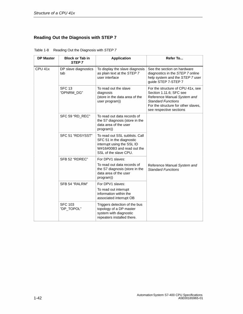
Structure of a CPU 41x
1-42Automation System S7-400 CPU Specifications
A5E00165965-01
Reading Out the Diagnosis with STEP 7
Table 1-8 Reading Out the Diagnosis with STEP 7
DP Master Block or Tab inSTEP 7
Application Refer To...
CPU 41x DP slave diagnosticstab
To display the slave diagnosisas plain text at the STEP 7user interface
See the section on hardwarediagnostics in the STEP 7 onlinehelp system and the STEP 7 userguide STEP 7-STEP 7
SFC 13“DPNRM_DG”
To read out the slavediagnosis(store in the data area of theuser program))
For the structure of CPU 41x, seeSection 1.11.6; SFC seeReference Manual System andStandard FunctionsFor the structure for other slaves,see respective sections
SFC 59 “RD_REC” To read out data records ofthe S7 diagnosis (store in thedata area of the userprogram))
SFC 51 “RDSYSST” To read out SSL sublists. CallSFC 51 in the diagnosticinterrupt using the SSL IDW#16#00B3 and read out theSSL of the slave CPU.
SFB 52 “RDREC” For DPV1 slaves:
To read out data records ofthe S7 diagnosis (store in thedata area of the userprogram))
Reference Manual System andStandard Functions
SFB 54 “RALRM” For DPV1 slaves:
To read out interruptinformation within theassociated interrupt OB
SFC 103 ”DP_TOPOL”
Triggers detection of the bustopology of a DP mastersystem with diagnosticrepeaters installed there.
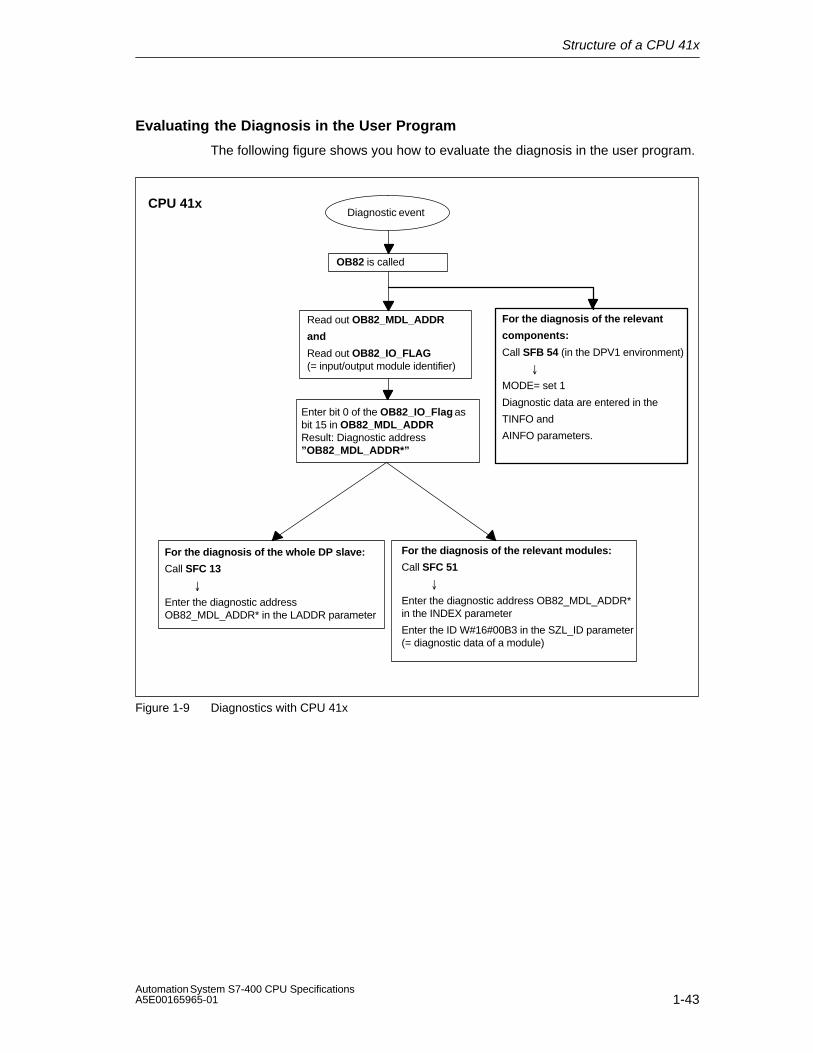
Structure of a CPU 41x
1-43Automation System S7-400 CPU SpecificationsA5E00165965-01
Evaluating the Diagnosis in the User Program
The following figure shows you how to evaluate the diagnosis in the user program.
Diagnostic event
Read out OB82_MDL_ADDR
and
Read out OB82_IO_FLAG (= input/output module identifier)
For the diagnosis of the whole DP slave:
Call SFC 13
�
Enter the diagnostic addressOB82_MDL_ADDR* in the LADDR parameter
Enter bit 0 of the OB82_IO_Flag asbit 15 in OB82_MDL_ADDRResult: Diagnostic address”OB82_MDL_ADDR*”
For the diagnosis of the relevant modules:
Call SFC 51
�
Enter the diagnostic address OB82_MDL_ADDR*in the INDEX parameter
Enter the ID W#16#00B3 in the SZL_ID parameter(= diagnostic data of a module)
CPU 41x
OB82 is called
For the diagnosis of the relevant
components:
Call SFB 54 (in the DPV1 environment)
�
MODE= set 1
Diagnostic data are entered in the
TINFO and
AINFO parameters.
Figure 1-9 Diagnostics with CPU 41x

Structure of a CPU 41x
1-44Automation System S7-400 CPU Specifications
A5E00165965-01
Diagnostic Addresses in Connection with DP Slave Functionality
You assign diagnostic addresses for the PROFIBUS DP in the CPU 41x. Ensureduring configuration that DP diagnostic addresses are assigned once to the DPmaster and once to the DP slave.
Specify two diagnostic addresses during configuration:
PROFIBUS
S7 CPU as DP slaveS7 CPU as DP master
Diagnostic address Diagnostic address
During the configuration of the DPmaster, you specify (in the associatedproject of the DP master) a diagnosticaddress for the DP slave. In thefollowing, this diagnostic address isdescribed as being assigned to the DPmaster.
During the configuration of the DP slave,you also specify (in the associatedproject of the DP slave) a diagnosticaddress that is assigned to the DP slave.In the following, this diagnostic addressis described as being assigned to theDP slave.
By means of this diagnostic address theDP master receives information on thestatus of the DP slave or a businterruption (see also Table 1-9).
By means of this diagnostic address theDP slave receives information on thestatus of the DP master or a businterruption (see also Table 1-13).
Figure 1-10 Diagnostic Addresses for the DP Master and DP Slave

Structure of a CPU 41x
1-45Automation System S7-400 CPU SpecificationsA5E00165965-01
Event Detection
Table 1-9 shows you how the CPU 41x as DP master detects any changes in theoperating mode of a CPU as DP slave or interruptions in data transfer.
Table 1-9 Event Detection of the CPUs 41x as DP Master
Event What Happens in the DP Master
Businterruption(short circuit,connectorremoved)
• OB 86 called with the message Station failure (incoming event; diagnostic address of the DP slave that is assigned to the DP master)
• In the case of I/O access: OB 122 called (I/O access error)
DP slave: RUN → STOP
• OB 82 is called with the message Faulty module(incoming event; diagnostic address of the DP slave that is assignedto the DP master; Variable OB82_MDL_STOP=1)
DP slave: STOP → RUN
• OB 82 is called with the message Module OK.(outgoing event; diagnostic address of the DP slave that is assignedto the DP master; Variable OB82_MDL_STOP=0)
Evaluation in the User Program
The following table shows you how, for example, you can evaluate RUN-STOPtransitions of the DP slave in the DP master (see also Table 1-9).
In the DP Master In the DP Slave (CPU 41x)
Diagnostic addresses: (example)Master diagnostic address=1023Slave diagnostic address in the mastersystem=1022
Diagnostic addresses: (example)Slave diagnostic address=422Master diagnostic address=not relevant
The CPU calls OB 82 with the followinginformation, amongst other things:
• OB 82_MDL_ADDR:=1022
• OB82_EV_CLASS:=B#16#39(incoming event)
• OB82_MDL_DEFECT:=modulemalfunction
Tip: This information is also in the diagnosticbuffer of the CPU
You should also program the SFC 13“DPNRM_DG” in the user program to readout the DP slave diagnostic data.
We recommend you use SFB 54 in the DPV1environment. It outputs the interruptinformation in its entirety.
CPU: RUN → STOP
CPU generates a DP slave diagnostic frame .
Structure of a CPU 41x
1-46Automation System S7-400 CPU Specifications
A5E00165965-01
1.11.5 CPU 41x as DP Slave
Introduction
In this section we describe the features and technical specifications of the CPU ifyou operate it as a DP slave.
You can find the features and technical specifications of the CPUs 41x as of Section 4.1.
Requirements
1. Only one DP interface of a CPU can be configured as a DP slave.
2. Is the MPI/DP interface to be a DP interface? If so, you must configure theinterface as a DP interface.
Before commissioning you must configure the CPU as a DP slave. In otherwords, you must do the following in STEP 7
– Activate the CPU as a DP slave
– Assign a PROFIBUS address
– Assign a slave diagnostic address
– Define the address areas for data transfer to the DP master
DDB (GSD) Files
You need a DDB file to configure the CPU as a DP slave in a third-party system.
You can download the GSD file free of charge from the Internet athttp://www.ad.siemens.de/csi_e/gsd.
You can also download the GSD file from the mailbox of the Interface Center inFürth on +49 (911) 737972.
Configuration and Parameter Assignment Frame
When you configure and assign parameters to CPU 41x, you are supported bySTEP 7. If you require a description of the configuration and parameter assignmentframe to carry out a check with a bus monitor, for example, you will find it on theInternet at http://www.ad.siemens.de/simatic-cs under the ID 1452338

Structure of a CPU 41x
1-47Automation System S7-400 CPU SpecificationsA5E00165965-01
Monitor/Modify, Programming via PROFIBUS
As an alternative to the MPI interface, you can use the PROFIBUS DP interface toprogram the CPU or execute the programming device functions Monitor andModify. To do this, you must enable these functions when you configure the CPUas DP slave in STEP 7.
Note
The use of Programming or Monitor and Modify via the PROFIBUS DP interfaceextends the DP cycle.
Data Transfer Via an Intermediate Memory
As a DP slave the CPU 41x makes an intermediate memory available toPROFIBUS DP. Data transfer between the CPU as DP slave and the DP masteralways takes place via this intermediate memory. You can configure up to32 address areas for this.
In other words, the DP master writes its data in these address areas of theintermediate memory and the CPU reads the data in the user program and viceversa.
Intermediatememory in the I/Oaddress area
PROFIBUS
I/O
CPU 41x as DP slaveDP master
I/O
Figure 1-11 Intermediate Memory in the CPU 41x as DP Slave

Structure of a CPU 41x
1-48Automation System S7-400 CPU Specifications
A5E00165965-01
Address Areas of the Intermediate Memory
Configure in STEP 7 the input and output address areas:
• You can configure up to 32 input and output address areas.
• Each of these address areas can be up to 32 bytes in size
• You can configure a maximum of 244 bytes of inputs and 244 bytes of outputsin total
An example for the configuration of the address assignments of the intermediatememory is provided in the table below. You will also find this in the online help forSTEP 7 configuration.
Table 1-10 Configuration Example for the Address Areas of the Intermediate Memory
Type Master Address Type Slave Address Length Unit Consistency
1 e 222 A 310 2 Byte Unit
2 A 0 e 13 10 Word Total length
:
32
Address areas in the DPmaster CPU
Address areas in the DPslave CPU
These parameters of the addressareas must be the same for the DPmaster and DP slave
Rules
You must adhere to the following rules when working with the intermediatememory:
• Assignment of the address areas:
– Input data of the DP slave are always output data of the DP master
– Output data of the DP slave are always input data of the DP master
• You can assign the addresses as you choose. You access the data in the userprogram with load/transfer commands or with SFCs 14 and 15. You can alsospecify addresses from the process image input and output table (see alsosection 1.11.1).

Structure of a CPU 41x
1-49Automation System S7-400 CPU SpecificationsA5E00165965-01
Note
You assign addresses for the intermediate memory from the DP address area ofthe CPU 41x.
You must not reassign the addresses you have already assigned to theintermediate memory to the I/O modules on the CPU 41x.
• The lowest address in each address area is the start address of that addressarea.
• The length, unit and consistency of address areas for the DP master and DPslave that belong together must be the same.
S5 DP Master
If you use an IM 308 C as a DP master and the CPU 41x as a DP slave, thefollowing applies to the exchange of consistent data:
You must program FB 192 in the IM 308-C so that consistent data can betransferred between the DP master and DP slave. The data of the CPU 41x areonly output or displayed contiguously in a block with FB 192.
S5-95 as DP Master
If you use an AG S5-95 as a DP master, you must also set its bus parameters forthe CPU 41x as DP slave.

Structure of a CPU 41x
1-50Automation System S7-400 CPU Specifications
A5E00165965-01
Sample Program
The small sample program below illustrates data transfer between the DP masterand DP slave. This example contains the addresses from Table 1-10.
In the DP Slave CPU In the DP Master CPU
L 2T MB 6L EB 0T MB 7
Preprocess datain the DP slave
L MW 6T PQW 310
Transfer data tothe DP master
L PIB 222T MB 50L PIB 223L B#16#3+ IT MB 51
Continue toprocess receiveddata in the DPmaster
L 10+ 3T MB 60
Preprocess datain the DP master
CALL SFC 15 LADDR:= W#16#0 RECORD:= P#M60.0 Byte20 RET_VAL:= MW 22
Send data to theDP slave
CALL SFC 14 LADDR:=W#16#D RET_VAL:=MW 20 RECORD:=P#M30.0 Byte20
Receive datafrom the DPmaster
L MB 30L MB 7+ IT MW 100
Continue toprocess receiveddata
Data Transfer in STOP Mode
The DP slave CPU goes into STOP mode: The data in the intermediate memory ofthe CPU are overwritten with “0”. In other words, the DP master reads “0”.
The DP master goes into STOP mode: The current data in the intermediatememory of the CPU are retained and can continue to be read by the CPU.
PROFIBUS Address
You cannot set 126 as PROFIBUS address for the CPU 41x as DP slave.

Structure of a CPU 41x
1-51Automation System S7-400 CPU SpecificationsA5E00165965-01
1.11.6 Diagnostics of the CPU 41x as DP Slave
Diagnostics using LEDs – CPU 41x
Table 1-11 explains the meaning of the BUSF LEDs.The BUSF LED assigned to the interface configured as the PROFIBUS DPinterface will always light up or flash.
Table 1-11 Meaning of the BUSF LEDs of the CPU 41x as DP Slave
BUSF Meaning What to Do
Off Configuration correct –
Flashing The CPU 41x is incorrectly configured.There is no data interchange betweenthe DP master and the CPU 41x.
Causes:
•
• Check the CPU 41x.
• Check to make sure that the bus connector isproperly inserted.
• Check whether the bus cable to the DP master• The response monitoring time has
expired.
• Bus communication viaPROFIBUS DP has been interrupted.
• The PROFIBUS address is incorrect.
has been interrupted.
• Check the configuration and parameterassignment.
• •On • Bus short circuit • Check the bus setup.
Triggering Detection of the Bus Topology in a DP Master System with the SFC 103“DP_TOPOL”
The diagnostics repeater is provided to improve the ability to locate disruptedmodules or an interruption on the DP cables when failures occur in ongoingoperation. This module operates as a slave and can determine the topology of aDP strand and record any faults originating from it.
You can use SFC 103 “DP_TOPOL” to trigger the analysis of the bus topology of aDP master systems by the diagnostics repeater. SFC 103 is documented in thecorresponding online help and in the manual “System and Standard Functions”.The diagnostics repeater is documented in the manual “Diagnostics Repeater forPROFIBUS DP”, order number 6ES7-972-0AB00-8BA0.
Diagnostics with STEP 5 or STEP 7 Slave Diagnostics
The slave diagnosis complies with the EN 50170, Volume 2, PROFIBUS standard.Depending on the DP master, it can be read out with STEP 5 or STEP 7 for all DPslaves that comply with the standard.
The display and structure of the slave diagnosis is described in the followingsections.

Structure of a CPU 41x
1-52Automation System S7-400 CPU Specifications
A5E00165965-01
S7 Diagnosis
An S7 diagnosis can be requested for all diagnostics-capable modules in theSIMATIC S7/M7 range of modules in the user program. You can find out whichmodules have diagnostic capability in the module information or in the catalog. Thestructure of the S7 diagnostic data is the same for both central and distributedmodules.
The diagnostic data of a module is in data records 0 and 1 of the system data areaof the module. Data record 0 contains 4 bytes of diagnostic data describing thecurrent status of a module. Data record 1 also contains module-specific diagnosticdata.
You will find the structure of the diagnostic data described in the Standard andSystem Functions Reference Manual.
Reading Out the Diagnosis
Table 1-12 Reading Out the Diagnostic Data with STEP 5 and STEP 7 in the Master System
Automation Systemwith DP Master
Block or Tab inSTEP 7
Application Refer To...
SIMATIC S7/M7 DP slave diagnosticstab
To display the slavediagnosis as plain text atthe STEP 7 user interface
See the section onhardware diagnostics inthe STEP 7 online helpsystem and in the STEP 7user guide STEP 7
SFC 13“DP NRM_DG”
To read out the slavediagnosis(store in the data area ofthe user program))
SFC see ReferenceManual System andStandard Functions
SFC 51 “RDSYSST” To read out SSL sublistsCall SFC 51 in thediagnostic interrupt usingthe SSL ID W#16#00B3and read out the SSL of theslave CPU.
See the System andStandard FunctionsReference Manual
SFB 54 “RDREC” Applies to the DPV1environment: To read outinterrupt information withinthe associated interrupt OB
Reference Manual
FB 125/FC 125 To evaluate slave diagnosis The Internet pagehttp://www.ad.siemens.de/simatic-cs
ID 387 257
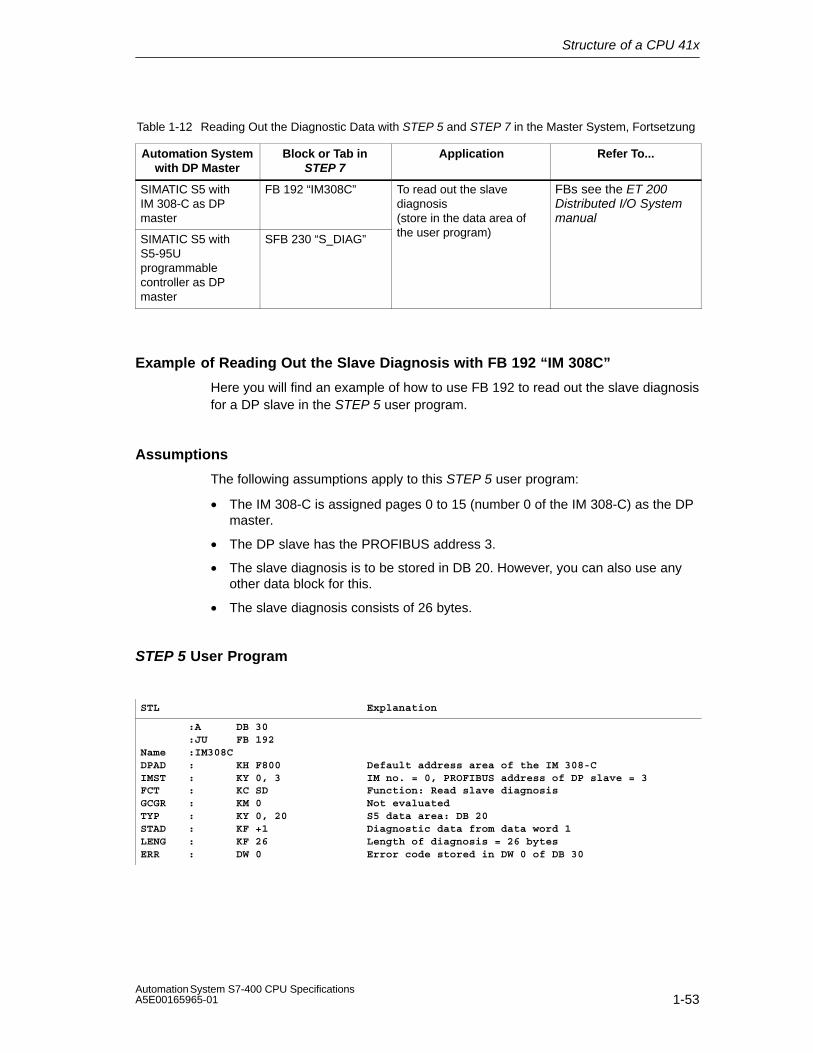
Structure of a CPU 41x
1-53Automation System S7-400 CPU SpecificationsA5E00165965-01
Table 1-12 Reading Out the Diagnostic Data with STEP 5 and STEP 7 in the Master System, Fortsetzung
Automation Systemwith DP Master
Refer To...ApplicationBlock or Tab inSTEP 7
SIMATIC S5 withIM 308-C as DPmaster
FB 192 “IM308C” To read out the slavediagnosis(store in the data area of
FBs see the ET 200Distributed I/O Systemmanual
SIMATIC S5 withS5-95Uprogrammablecontroller as DPmaster
SFB 230 “S_DIAG” the user program)
Example of Reading Out the Slave Diagnosis with FB 192 “IM 308C”
Here you will find an example of how to use FB 192 to read out the slave diagnosisfor a DP slave in the STEP 5 user program.
Assumptions
The following assumptions apply to this STEP 5 user program:
• The IM 308-C is assigned pages 0 to 15 (number 0 of the IM 308-C) as the DPmaster.
• The DP slave has the PROFIBUS address 3.
• The slave diagnosis is to be stored in DB 20. However, you can also use anyother data block for this.
• The slave diagnosis consists of 26 bytes.
STEP 5 User Program
STL Explanation
:A DB 30:JU FB 192
Name :IM308CDPAD : KH F800IMST : KY 0, 3FCT : KC SDGCGR : KM 0TYP : KY 0, 20STAD : KF +1LENG : KF 26ERR : DW 0
Default address area of the IM 308-CIM no. = 0, PROFIBUS address of DP slave = 3Function: Read slave diagnosisNot evaluatedS5 data area: DB 20Diagnostic data from data word 1Length of diagnosis = 26 bytesError code stored in DW 0 of DB 30
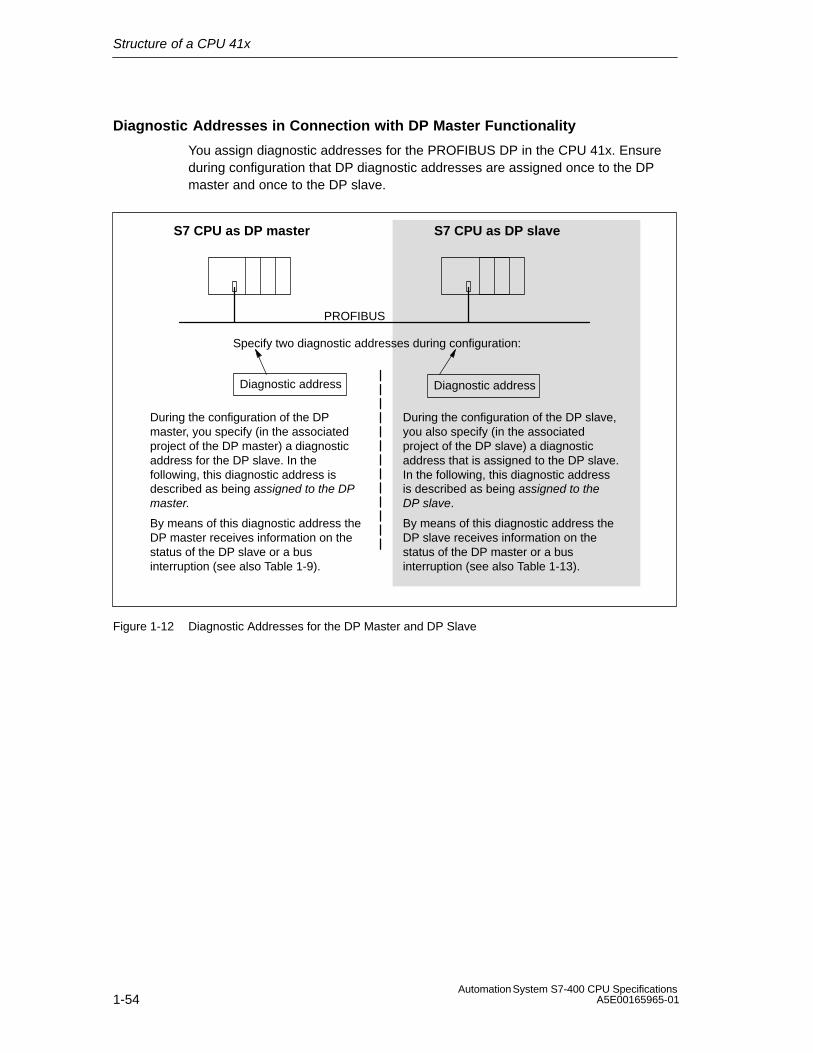
Structure of a CPU 41x
1-54Automation System S7-400 CPU Specifications
A5E00165965-01
Diagnostic Addresses in Connection with DP Master Functionality
You assign diagnostic addresses for the PROFIBUS DP in the CPU 41x. Ensureduring configuration that DP diagnostic addresses are assigned once to the DPmaster and once to the DP slave.
Specify two diagnostic addresses during configuration:
PROFIBUS
S7 CPU as DP slaveS7 CPU as DP master
Diagnostic address Diagnostic address
During the configuration of the DPmaster, you specify (in the associatedproject of the DP master) a diagnosticaddress for the DP slave. In thefollowing, this diagnostic address isdescribed as being assigned to the DPmaster.
During the configuration of the DP slave,you also specify (in the associatedproject of the DP slave) a diagnosticaddress that is assigned to the DP slave.In the following, this diagnostic addressis described as being assigned to theDP slave.
By means of this diagnostic address theDP master receives information on thestatus of the DP slave or a businterruption (see also Table 1-9).
By means of this diagnostic address theDP slave receives information on thestatus of the DP master or a businterruption (see also Table 1-13).
Figure 1-12 Diagnostic Addresses for the DP Master and DP Slave

Structure of a CPU 41x
1-55Automation System S7-400 CPU SpecificationsA5E00165965-01
Event Detection
Table 1-13 shows you how the CPU 41x as DP slave detects any operating modechanges or interruptions in data transfer.
Table 1-13 Event Detection of the CPUs 41x as DP Slave
Event What Happens in the DP Slave
Bus interruption(short circuit,connector removed)
• OB 86 is called with the message Station failure (incoming event; diagnostic address of the DP slave that isassigned to the DP slave)
• In the case of I/O access: OB 122 called (I/O access error)
DP master: RUN → STOP
• OB 82 is called with the message Faulty module(incoming event; diagnostic address of the DP slave that is assigned to theDP slave; Variable OB82_MDL_STOP=1)
DP master: STOP → RUN
• OB 82 is called with the message Module OK. (outgoing event; diagnostic address of the DP slave that is assigned to theDP slave; Variable OB82_MDL_STOP=0)
Evaluation in the User Program
The following table 1-14 shows you, for example, how you can evaluateRUN-STOP transitions of the DP master in the DP slave (see also Table 1-13).
Table 1-14 Evaluation of RUN-STOP Transitions in the DP Master/DP Slave
In the DP Master In the DP Slave
Diagnostic addresses: (example)Master diagnostic address=1023Slave diagnostic address in the mastersystem=1022
Diagnostic addresses: (example)Slave diagnostic address=422Master diagnostic address=not relevant
CPU: RUN → STOP The CPU calls OB 82 with the followinginformation, amongst other things:
• OB 82_MDL_ADDR:=422
• OB82_EV_CLASS:=B#16#39(incoming event)
• OB82_MDL_DEFECT:=modulemalfunction
Tip: This information is also in the diagnosticbuffer of the CPU
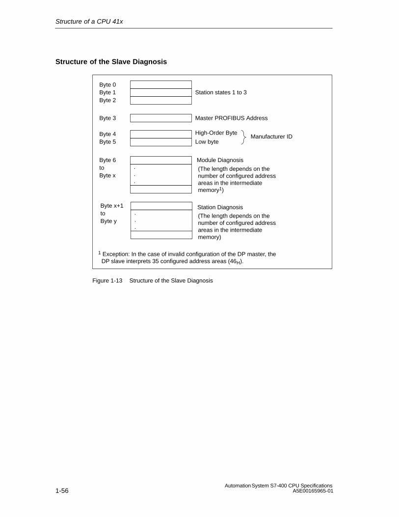
Structure of a CPU 41x
1-56Automation System S7-400 CPU Specifications
A5E00165965-01
Structure of the Slave Diagnosis
Byte 0Byte 1 Station states 1 to 3Byte 2
Byte 3 Master PROFIBUS Address
Byte 4Byte 5 Low byte
High-Order ByteManufacturer ID
Byte 6to
Module Diagnosis
Byte x
Station Diagnosis...
.
.
.
Byte x+1toByte y
(The length depends on thenumber of configured addressareas in the intermediatememory1)
(The length depends on thenumber of configured addressareas in the intermediatememory)
1 Exception: In the case of invalid configuration of the DP master, the DP slave interprets 35 configured address areas (46H).
Figure 1-13 Structure of the Slave Diagnosis

Structure of a CPU 41x
1-57Automation System S7-400 CPU SpecificationsA5E00165965-01
1.11.7 CPU 41x as DP slave: Station States 1 to 3
Station states 1 to 3
Station status 1 to 3 provides an overview of the status of a DP slave.
Table 1-15 Structure of the Station Status 1 (Byte 0)
Bit Meaning What to Do
0 1: The DP slave cannot be addressed bythe DP master.
• Correct DP address set on the DP slave?
• Bus connector connected?
• Voltage on DP slave?
• RS 485 repeater set correctly?
• Execute reset on the DP slave
1 1: The DP slave is not yet ready for datatransfer.
• Wait while the DP slave powers up.
2 1: The configuration data sent by the DPmaster to the DP slave does notcorrespond to the actual configuration ofthe DP slave.
• Correct station type or correct configuration ofthe DP slave entered in the software?
3 1: Diagnostic interrupt, triggered byRUN-STOP transition of the CPU
0: Diagnostic interrupt, triggered bySTOP-RUN transition of the CPU
• You can read out the diagnosis.
4 1:Function is not supported, e.g. changingthe DP address via software
• Check the configuration.
5 0: The bit is always “0”. –
6 1: The DP slave type does not correspondto the software configuration.
• Correct station type entered in the software?(Parameter assignment error)
7 1: Parameters have been assigned to theDP slave by a different DP master to theone that currently has access to the DPslave.
• Bit is always at 1, when you are accessing theDP slave using the programming device oranother DP master, for example.
The DP address of the parameter assignmentmaster is in the “master PROFIBUS address”diagnostic byte.

Structure of a CPU 41x
1-58Automation System S7-400 CPU Specifications
A5E00165965-01
Table 1-16 Structure of Station Status 2 (Byte 1)
Bit Meaning
0 1: The DP slave must be assigned new parameters and reconfigured.
1 1: A diagnostic message has been issued. The DP slave cannot continue until the problem hasbeen corrected (static diagnostic message).
2 1: The bit is always set to “1” if the DP slave with this DP address is present.
3 1: Response monitoring is enabled for this DP slave.
4 0: The bit is always at “0”.
5 0: The bit is always at “0”.
6 0: The bit is always at “0”.
7 1: The DP slave is disabled – that is, it has been removed from cyclic processing.
Table 1-17 Structure of Station Status 3 (Byte 2)
Bit Meaning
0
to
6
0: The bits are always at “0”.
7 1: • There are more diagnostic messages than the DP slave can store.
• The DP master cannot enter all the diagnostic messages sent by the DP slave in itsdiagnostic buffer.
Master PROFIBUS Address
The master PROFIBUS address diagnostic byte contains the DP address of theDP master that:
• Assigns parameters for the DP slave and
• Has read and write access to the DP slave
Table 1-18 Structure of the Master PROFIBUS Address (Byte 3)
Bit Meaning
0 to 7 DP address of the DP master that configured the DP slave and has read and write access tothe DP slave.
FFH: DP slave has not been configured by any DP master.

Structure of a CPU 41x
1-59Automation System S7-400 CPU SpecificationsA5E00165965-01
Manufacturer ID
The manufacturer ID contains a code that describes the type of the DP slave.
Table 1-19 Structure of the Manufacturer ID (Bytes 4, 5)
Byte 4 Byte 5 Manufacturer ID for CPU
80H C5H 412-1
80H C6H 412-2
80H C7H 414-2
80H C8H 414-3
80H CAH 416-2
80H CBH 416-3
80H CCH 417-4
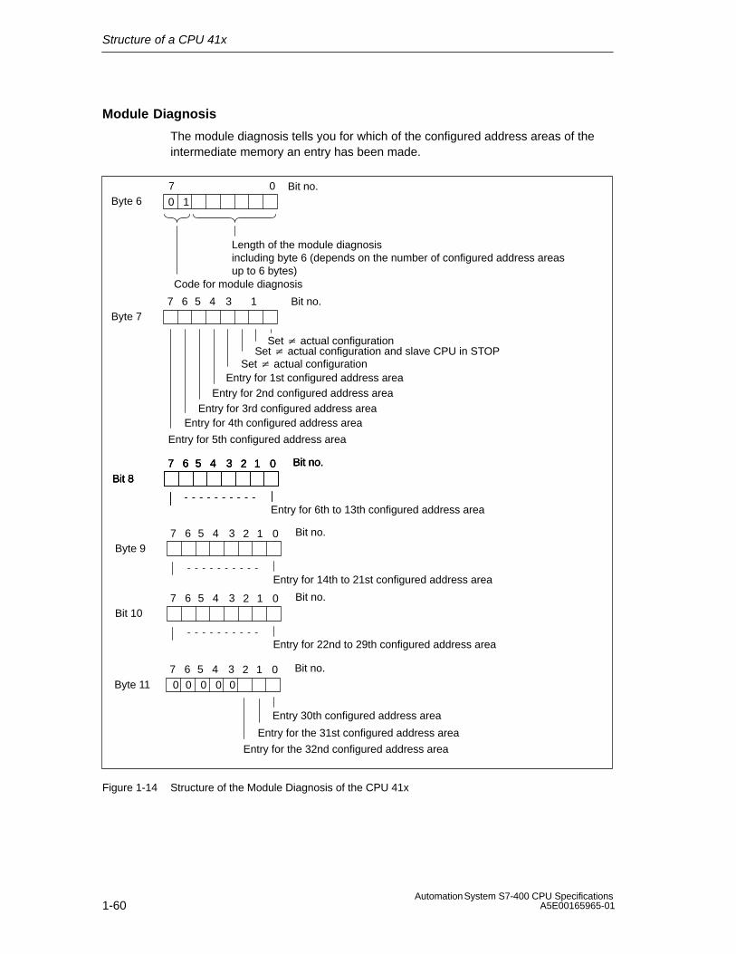
Structure of a CPU 41x
1-60Automation System S7-400 CPU Specifications
A5E00165965-01
Module Diagnosis
The module diagnosis tells you for which of the configured address areas of theintermediate memory an entry has been made.
Byte 67 0 Bit no.
Length of the module diagnosis including byte 6 (depends on the number of configured address areasup to 6 bytes)
Byte 7
Set � actual configuration and slave CPU in STOP
Entry for 2nd configured address areaEntry for 3rd configured address area
Entry for 4th configured address area
Entry for 5th configured address area
Bit 8
Entry for 6th to 13th configured address area
Code for module diagnosis
0 1
7 6 5 4 1
02 1
3
Entry for 1st configured address area
Bit no.
Bit no.7 6 5 4 3
Byte 11
Entry 30th configured address area
Entry for the 31st configured address area
02 1 Bit no.7 6 5 4 3
Bit 802 1 Bit no.7 6 5 4 3
Bit 802 1 Bit no.7 6 5 4 3
Byte 9
Entry for 14th to 21st configured address area
02 1 Bit no.7 6 5 4 3
Bit 10
Entry for 22nd to 29th configured address area
02 1 Bit no.7 6 5 4 3
Entry for the 32nd configured address area
00 00 0
Set � actual configuration
Set � actual configuration
Figure 1-14 Structure of the Module Diagnosis of the CPU 41x

Structure of a CPU 41x
1-61Automation System S7-400 CPU SpecificationsA5E00165965-01
Station Diagnosis
The station diagnosis provides detailed information on a DP slave. The stationdiagnosis starts as of byte x and can include up to 20 bytes.
The figure below illustrates the structure and contents of the bytes for a configuredaddress area of the intermediate memory.
Byte x+1 01H: Code for diagnostic interrupt02H: Code for process interrupt
Byte x +4tobyte x +7
Byte x7 0 Bit no.
Length of the module diagnosis including byte x (= maximum 20 bytes)
Code for station diagnosis
0 0
6
Byte x +2
Byte x +3
Number of the configured addressarea of the intermediate memoryThe following applies: Number+3(example:CPU = 02H1st address area = 04H2nd address area = 05H and so on)
(Fixed to 0)
Diagnostic data (see Figure 1-16)andinterrupt data
7 0
0 0 0 0 0 0 0 0
Figure 1-15 Structure of the Station Diagnosis

Structure of a CPU 41x
1-62Automation System S7-400 CPU Specifications
A5E00165965-01
As of byte x +4
The meaning of the bytes as of byte x+4 depends on byte x +1 (see Figure 1-15).
In Byte x +1, the Code Stands for:
Diagnostic Interrupt (01H) Process Interrupt (02H)
The diagnostic data contain the 16 bytestatus information of the CPU. Figure 1-16shows you the assignment of the first 4 bytesof the diagnostic data. The following 12 bytesare always 0.
You can program 4 bytes of interruptinformation any way you wish for the processinterrupt. You transfer these 4 bytes to the DPmaster in STEP 7 using SFC 7 “DP_PRAL”.
Bytes x+4 to x+7 for Diagnostic Interrupts
Figure 1-16 illustrates the structure and contents of bytes x +4 to x +7 for thediagnostic interrupt. The contents of these bytes correspond to the contents ofdata record 0 of the diagnosis in STEP 7 (in this case not all the bits are assigned).
Byte x +47 0 Bit no.
Byte x +5
Byte x +6
0: RUN mode1: STOP mode
0: Module OK.1: Faulty module
0
1
0 0 0 0
1
7 4 0
02
3 Bit no.
Bit no.7 027
0 0
0 0 00 01
Identifier for address area of theintermediate memory (constant)
0000000
Byte x +77 0 Bit no.0 0 0 0 00 0 0
Figure 1-16 Bytes +4 to +7 for Diagnostic and Process Interrupts
Structure of a CPU 41x
1-63Automation System S7-400 CPU SpecificationsA5E00165965-01
Interrupts with the S7/M7 DP Master
In the CPU 41x as a DP slave you can trigger a process interrupt in the DP masterfrom the user program. You can trigger an OB 40 in the user program of the DPmaster by calling SFC 7 “DP_PRAL”. Using SFC 7 you can forward interruptinformation in a double word to the DP master, which you can evaluate in OB 40 inthe OB40_POINT_ADDR variable. You can program the interrupt information asyou choose. You will find a detailed description of SFC 7 “DP_PRAL” in the SystemSoftware for S7-300/400, System and Standard Functions Reference Manual.
Interrupts with another DP Master
If you are running the CPU 41x with another DP master, these interrupts arereflected in the station diagnosis of the CPU 41x. You have to process the relevantdiagnostic events in the DP master’s user program.
Note
Note the following in order to be able to evaluate diagnostic interrupts and processinterrupts by means of the station diagnosis when using a different DP master:
• The DP master should be able to store the diagnostic messages; in otherwords, the diagnostic messages should be stored in a ring buffer in the DPmaster. There are more diagnostic messages than the DP master can store,only the last diagnostic message received would be available for evaluation, forexample.
• You must query the relevant bits in the station diagnosis at regular intervals inyour user program. You must also take the PROFIBUS DP bus cycle time intoconsideration so that you can query the bits at least once synchronously withthe bus cycle time, for example.
• You cannot use process interrupts in the station diagnosis with an IM 308-C asthe DP master, because only incoming – and not outgoing – interrupts arereported.

Structure of a CPU 41x
1-64Automation System S7-400 CPU Specifications
A5E00165965-01
1.12 Direct Communication
You can configure direct communication for PROFIBUS nodes as of STEP 7 V 5.x.The CPU 41x can participate in direct communication as the sender or recipient.
“Direct Communication” represents a special type of communication relationshipbetween PROFIBUS DP nodes.
1.12.1 Principle of Direct Data
Direct communication is characterized by the fact that PROFIBUS DP nodes“listen in” to find out which data a DP slave is sending back to its DP master.By means of this mechanism the “eavesdropper” (recipient) can access changes tothe input data of remote DP slaves directly.
During configuration in STEP 7, you specify by means of the relevant I/O inputaddresses the address area of the recipient to which the required data of thesender are to be read.
A CPU 41x can be:Sender as a DP slaveRecipient as a DP slave or a DP master or as a CPU that is not
integrated in a master system (see Figure 1-17).

Structure of a CPU 41x
1-65Automation System S7-400 CPU SpecificationsA5E00165965-01
Example
Figure 1-17 uses an example to illustrate which direct communication“relationships” you can configure. All the DP masters and DP slaves in the figureare CPUs 41x. Note that other DP slaves (ET 200M, ET 200X, ET 200S) can onlybe senders.
PROFIBUS
CPU 41x as DP master 1
CPU 41x-2
DP slave 3 DP slave 5CPU 41x as DPslave 1
DP mastersystem 1
DP mastersystem 2
CPU 41x as DP master 2
CPU 41x as DPslave 2
CPU 41x as DPslave 4
Figure 1-17 Direct Communication with CPUs 41x
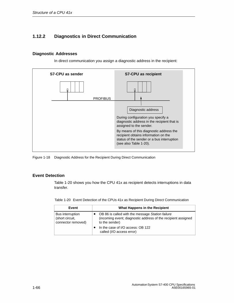
Structure of a CPU 41x
1-66Automation System S7-400 CPU Specifications
A5E00165965-01
1.12.2 Diagnostics in Direct Communication
Diagnostic Addresses
In direct communication you assign a diagnostic address in the recipient:
PROFIBUS
S7-CPU as recipientS7-CPU as sender
Diagnostic address
During configuration you specify adiagnostic address in the recipient that isassigned to the sender.
By means of this diagnostic address therecipient obtains information on thestatus of the sender or a bus interruption(see also Table 1-20).
Figure 1-18 Diagnostic Address for the Recipient During Direct Communication
Event Detection
Table 1-20 shows you how the CPU 41x as recipient detects interruptions in datatransfer.
Table 1-20 Event Detection of the CPUs 41x as Recipient During Direct Communication
Event What Happens in the Recipient
Bus interruption(short circuit,connector removed)
• OB 86 is called with the message Station failure (incoming event; diagnostic address of the recipient assignedto the sender)
• In the case of I/O access: OB 122 called (I/O access error)

Structure of a CPU 41x
1-67Automation System S7-400 CPU SpecificationsA5E00165965-01
Evaluation in the User Program
The following table 1-21 shows you, for example, how you can evaluate a senderstation failure in the recipient (see also Table 1-20).
Table 1-21 Evaluation of the Station Failure in the Sender During Direct Communication
In the Sender In the Recipient
Diagnostic addresses: (example)Master diagnostic address=1023Slave diagnostic address in the mastersystem=1022
Diagnostic address: (example)Diagnostic address=444
Station failure The CPU calls OB 86 with the followinginformation, amongst other things:
• OB 86_MDL_ADDR:=444
• OB86_EV_CLASS:=B#16#38(incoming event)
• OB86_FLT_ID:=B#16#C4 (failure of a DP station)
Tip: This information is also in the diagnosticbuffer of the CPU

Structure of a CPU 41x
1-68Automation System S7-400 CPU Specifications
A5E00165965-01
1.13 Consistent Data
Data that belongs together in terms of its content and a process state written at aspecific point in time is known as consistent data. To maintain consistency, thedata should not be changed or updated during processing or transmission.
Example
To ensure that the CPU has a consistent image of the process signals for theduration of cyclic program scanning, the process signals are read from the processimage inputs prior to program scanning and written to the process image outputsafter the program scanning. Subsequently, during program scanning when theaddress area “inputs” (I) and “outputs” (O) are addressed, the user programaddresses the internal memory area of the CPU on which the image of the inputsand outputs is located instead of directly accessing the signal modules.
SFC 81 “UBLKMOV”
With SFC 81 “UBLKMOV” (uninterruptible block move), you can copy the contentsof a memory area (= source area) consistently to a different memory area (=destination area). The copy operation cannot be interrupted by other operatingsystem activities.
SFC 81 “UBLKMOV” enables you to copy the following memory areas:
• Memory markers
• DB contents
• Process image of the inputs
• Process image of outputs
The maximum amount of data you can copy is 512 bytes. Take into considerationthe restrictions for the specific CPU, which are documented in the operations list,for example.
Since copying cannot be interrupted, the interrupt reaction times of your CPU mayincrease when using SFC 81 “UBLKMOV”.
The source and destination areas must not overlap. If the specified destinationarea is larger than the source area, the function only copies as much data to thedestination area as that contained in the source area. If the specified destinationarea is smaller than the source area, the function only copies as much data as canbe written to the destination area.
Structure of a CPU 41x
1-69Automation System S7-400 CPU SpecificationsA5E00165965-01
1.13.1 Consistency for Communication Blocks and Functions
Using S7-400 the communication data is not processed in the scan cyclecheckpoint; instead, this data is processed in fixed time slices during the programcycle.
In the system the byte, word and double word data formats can always beprocessed consistently, in other words, the transfer or processing of 1 byte, 1 word(= 2 bytes) or 1 double word (= 4 bytes) cannot be interrupted.
If communication blocks (such as SFB 12 “BSEND”) are called in the userprogram, which are only used in pairs (such as SFB 12 “BSEND” und SFB 13“BRCV”) and which share access to data, the access to this data area can becoordinated between themselves, using the “DONE” parameter, for example. Dataconsistency of the communication areas transmitted locally with a communicationblock can thus be ensured in the user program.
S7 communication functions such as SFB 14 “GET”, SFB 15 “PUT” reactdifferently because no block is needed in the user program of the destinationdevice. In this case the size of data consistency has to be taken into accountbeforehand during the programming phase.
1.13.2 Access to the Working Memory of the CPU
The communication functions of the operating system access the working memoryof the CPU in fixed block lengths. The block size is a variable length up to amaximum of 462 bytes.
1.13.3 Read from and Writing to a DP Standard Slave Consistently
Writing Data Consistently to a DP Standard Slave Using SFC 14 “DPRD_DAT”
Using SFC 14 “DPRD_DAT” (read consistent data of a DP standard slave) you canconsistently read the data of a DP standard slave.
The data read is entered into the destination range defined by RECORD if no erroroccurs during the data transmission.
The destination range must have the same length as the one you have configuredfor the selected module with STEP 7.
By invoking SFC 14 you can only access the data of one module / DP ID at theconfigured start address.
Structure of a CPU 41x
1-70Automation System S7-400 CPU Specifications
A5E00165965-01
1.13.4 Writing Data Consistently to a DP Standard Slave Using SFC 15“DPWR_DAT”
Using SFC 15 “DPWR_DAT” (write consistent data to a DP standard slave) youcan consistently write data to the DP standard slave addressed in the RECORD.
The source range must have the same length as the one you have configured forthe selected module with STEP 7.
Note
The Profibus DP standard defines the upper limit for the transmission of consistentuser data (see following section). Typical DP standard slaves adhere to this upperlimit. In older CPUs (<1999) there are restrictions in the transmission of consistentuser data depending on the CPU. For these CPUs you can determine themaximum length of the data which the CPU can consistently read and write to andfrom the DP standard in the respective technical specifications under the indexentry “DP Master – User data per DP slave”. Newer CPUs are capable ofexceeding the value for the amount of data that a DP standard slave can send andreceive.
Upper Limit for the Transmission of Consistent User Data on a DP Slave
The Profibus DP standard defines the upper limit for the transmission of consistentuser data to a DP slave. For this reason a maximum of 64 words = 128 bytes ofuser data can be consistently transferred in a block to the DP slave.
During the configuration you can determine the size of the consistent area. Youcan set a maximum length of consistent data at 64 words = 128 bytes in thespecial identification format (SKF) (128 bytes for inputs and 128 bytes for outputs);the data block size cannot exceed this.
This upper limit only applies to pure user data. Diagnostics and parameter data areregrouped into full records and therefore always transferred consistently.
In the general identification format (AKF) the maximum length of consistent datacan be set at 16 words = 32 bytes (32 bytes for inputs and 32 bytes for outputs);the data block size cannot exceed this.
Note in this context that a CPU 41x in a general environment acting as a DP slaveon a third-party master (connection defined by GSD) has to be configured with thegeneral identification format. The transfer memory of a CPU 41x acting as a DPslave to the PROFIBUS DP can therefore be a maximum of 16 words = 32 bytes.

Structure of a CPU 41x
1-71Automation System S7-400 CPU SpecificationsA5E00165965-01
1.13.5 Consistent Data Access without the Use of SFC 14 or SFC 15
Consistent data access of > 4 bytes without using SFC 14 or SFC 15 is possiblefor the CPUs listed below. The data area of a DP slave that should transferconsistently is transferred to a process image partition. The information in this areaare therefore always consistent. You can subsequently use load/transfercommands (such as L EW 1) to access the process image. This is an especiallyconvenient and efficient (low runtime load) way to access consistent data. Thisallows efficient integration and configuration of drives or other DP slaves, forexample.
This applies to CPUs with firmware version 3.0 or later:
S7-400 CPU MLFB
CPU 412-1 6ES7412-1XF03-0AB0
CPU 412-2 6ES7412-2XG00-0AB0
CPU 414-2 6ES7414-2XG03-0AB0
CPU 414-3 6ES7414-3XJ00-0AB0
CPU 416-2 6ES7416-2XK02-0AB0
CPU 416-3 6ES7416-3XL00-0AB0
CPU 417-4 6ES7417-4XL00-0AB0
No I/O access error occurs with direct access (e.g. L PEW or T PAW).
The following is important for converting from the SFC14/15 method to the processimage method:
• When converting from the SFC14/15 method to the process image method, it isnot recommended to use the system functions and the process image at thesame time. Although the process image is updated when writing with thesystem function SFC15, this is not the case when reading. In other words, theconsistency between the process image values and the values of the systemfunction SFC14 is not ensured.
• SFC 50 “RD_LGADR” outputs another address area with the SFC 14/15method as with the process image method.
• If you are using a CP 443-5 ext the simultaneous use of SFC 14/15 and theprocess image results in the following errors, you cannot read/write into theprocess image and/or you can no longer read/write with SFC 14/15.

Structure of a CPU 41x
1-72Automation System S7-400 CPU Specifications
A5E00165965-01
Example:
The following example (of the process image partition 3 “TPA 3”) shows such aconfiguration in HW Config:
• TPA 3 at output: These 50 bytes are stored consistent in the process imagepartition 3 (pull-down list “Consistent over –> entire length”) and can thereforebe read through the normal “load input xy” commands.
• Selecting “Process Image Partition –> –––” under input in the pull-down menumeans: do not store in a process image. Then the handling can only beperformed using the system functions SFC14/15.

2-1Automation System S7-400 CPU SpecificationsA5E00165965-01
Memory Concept and Startup Scenarios
Chapter Overview
In Section Description On Page
2.1 Overview of the Memory Concept of S7-400 CPUs 2-2
2.2 Overview of the Startup Scenarios for S7-400-CPUs 2-5
2

Memory Concept and Startup Scenarios
2-2Automation System S7-400 CPU Specifications
A5E00165965-01
2.1 Overview of the Memory Concept of S7-400 CPUs
Subdivision of the Memory Areas
You can divide the memory of the S7 CPUs into the following areas:
Integrated load memory
RAM with battery backup
External load memory
RAM with battery backup or retentive flash memory
Working memory code
For the program
RAM with battery backup
Process input and outputimage
Diagnostic buffer
Working memory data
For data
RAM with battery backup
Local data stack
Load memory
For project data (blocks,symbols, comments, configu-ration and parameter assignment data)
Working memory
For runtime-relevant blocks
System memoryContains memory marker, timers,counters,
block stack and interrupt stack
RAM with battery backup
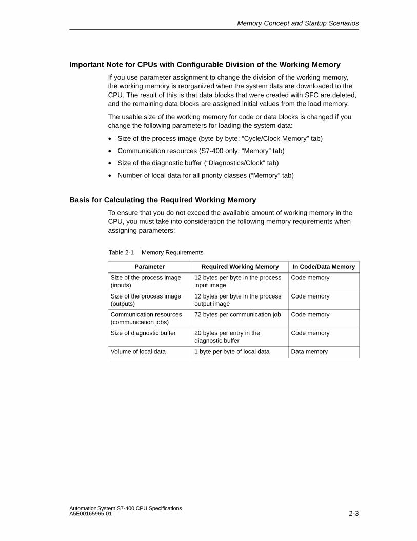
Memory Concept and Startup Scenarios
2-3Automation System S7-400 CPU SpecificationsA5E00165965-01
Important Note for CPUs with Configurable Division of the Working Memory
If you use parameter assignment to change the division of the working memory,the working memory is reorganized when the system data are downloaded to theCPU. The result of this is that data blocks that were created with SFC are deleted,and the remaining data blocks are assigned initial values from the load memory.
The usable size of the working memory for code or data blocks is changed if youchange the following parameters for loading the system data:
• Size of the process image (byte by byte; “Cycle/Clock Memory” tab)
• Communication resources (S7-400 only; “Memory” tab)
• Size of the diagnostic buffer (“Diagnostics/Clock” tab)
• Number of local data for all priority classes (“Memory” tab)
Basis for Calculating the Required Working Memory
To ensure that you do not exceed the available amount of working memory in theCPU, you must take into consideration the following memory requirements whenassigning parameters:
Table 2-1 Memory Requirements
Parameter Required Working Memory In Code/Data Memory
Size of the process image(inputs)
12 bytes per byte in the processinput image
Code memory
Size of the process image(outputs)
12 bytes per byte in the processoutput image
Code memory
Communication resources(communication jobs)
72 bytes per communication job Code memory
Size of diagnostic buffer 20 bytes per entry in thediagnostic buffer
Code memory
Volume of local data 1 byte per byte of local data Data memory

Memory Concept and Startup Scenarios
2-4Automation System S7-400 CPU Specifications
A5E00165965-01
Memory Types in S7-400 CPUs
• Load memory for project data, such as blocks, configuration and parameterassignment data, including symbols and comments as of version 5.1.
• Working memory for the runtime-relevant blocks (code blocks and data blocks).
• System memory (RAM) contains the memory elements that each CPU makesavailable to the user program, such as memory markers, timers, and counters.The system memory also receives the block stack and the interrupt stack.
• System memory of the CPU also makes temporary memory available (localdata stack, diagnostic buffer and communication resources) that is assigned tothe program when a block is called for its temporary data. These data are onlyvalid as long as the block is active.
By changing the default values for the process image, local data, diagnosticbuffer and communication resources (see the object properties of the CPU inHWCONFIG), you can control the working memory available to theruntime-relevant blocks.
Notice
Please note the following if you enlarge the process image of a CPU. Make surethat you configure the modules that can only be operated above the processimage in such a way that they are also positioned above the enlarged processimage. This particularly applies to IP and WF modules that you operate in the S5adapter casing in a S7 400.
Flexible Memory Capacity
• Working memory:
The capacity of the working memory is determined by selecting the appropriateCPU from the finely graded range of CPUs.
In the case of the CPU 417, working memory can be expanded.
• Load memory:
The integrated load memory is sufficient for small and medium-sized programs.
The load memory can be increased for larger programs by inserting the RAMmemory card.
Flash memory cards are also available to ensure that programs are retained inthe event of a power failure even if there isn’t a backup battery. Flash memorycards can also be used (as of 2 MB for standard CPUs, as of 4 MB forfault-tolerant CPUs) to send and execute operating system updates.
Backup
• The backup battery provides backup power for the integrated and external partof the load memory, the data section of the working memory and the codesection.

Memory Concept and Startup Scenarios
2-5Automation System S7-400 CPU SpecificationsA5E00165965-01
2.2 Overview of the Startup Scenarios for S7-400-CPUs
Cold Restart
• At a cold restart, all the data (process image, memory markers, timers,counters and data blocks) are reset to the start values stored in the program(load memory) - irrespective of whether they were configured as retentive ornon-retentive.
• Program processing is started from the beginning again (startup OB or OB 1).
Warm Restart
• At a warm restart, the process image and the non-retentive memory markers,timers and counters are reset.
Retentive memory markers, timers and counters and all the data blocks retaintheir last valid value.
• Program processing is started from the beginning again (startup OB or OB 1).
• When the power supply is interrupted, a warm restart is only possible inbacked-up mode.
Restart
• At a restart, all the data, including the process image, retain their last validvalue.
• Program processing is resumed at exactly the instruction at which theinterruption occurred.
• The outputs are not changed until the end of the current cycle.
• When the power supply is interrupted, a restart is only possible in backed-upmode.

Memory Concept and Startup Scenarios
2-6Automation System S7-400 CPU Specifications
A5E00165965-01

3-1Automation System S7-400 CPU SpecificationsA5E00165965-01
Cycle and Reaction Times of the S7-400
This chapter explains the composition of the cycle and reaction times of theS7-400.
You can display the cycle time of your user program on the relevant CPU using theprogramming device (see manual Configuring Hardware and CommunicationConnections with STEP 7 Version 5.0 or higher).
Examples will illustrate how you calculate the cycle time.
The reaction time is important for monitoring a process. This chapter provides adetailed description of how to calculate this. If you use a CPU 41x-2 DP as amaster in the PROFIBUS DP network, you also have to take into account DPcycle times (see Section 3.5).
Chapter Overview
Section Description Page
3.1 Cycle time 3-2
3.2 Cycle Time Calculation 3-4
3.3 Different Cycle Times 3-8
3.4 Communication Load 3-10
3.5 Reaction Time 3-13
3.6 How Cycle and Reaction Times Are Calculated 3-18
3.6 Examples of Calculating the Cycle Time and Reaction Time 3-18
3.8 Interrupt Reaction Time 3-22
3.9 Example of Calculating the Interrupt Reaction Time 3-24
3.10 Reproducibility of Time-Delay and Watchdog Interrupts 3-25
Further Information
You will find further information on the following processing times in the S7-400Instruction List. It lists all the STEP 7 instructions that can be processed by therelevant CPUs, together with their execution times and all the SFCs/SFBsintegrated in the CPUs and the IEC functions that can be called in STEP 7,together with their processing times.
3

Cycle and Reaction Times of the S7-400
3-2Automation System S7-400 CPU Specifications
A5E00165965-01
3.1 Cycle Time
In this chapter you will learn about the composition of the cycle time and how youcan calculate the cycle time.
Definition of the Cycle Time
The cycle time is the time which the operating system needs to process a programrun – in other words, an OB 1 run – and all the program segments and systemactivities that interrupt that run.
This time is monitored.
Time-Sharing Model
Cyclic program scanning, and thus also processing of the user program, isperformed in time slices. So that you can better appreciate these processes, wewill assume in the following that each time slice is exactly 1 ms long.
Process Image
The process signals are read or written prior to program scanning so that aconsistent image of the process signals is available to the CPU for the duration ofcyclic program scanning. Then the CPU does not directly access the signalmodules during program scanning when the address area “inputs” (I) and “outputs”(O) are addressed, but addresses instead the internal memory area of the CPU onwhich the image of the inputs and outputs is located.

Cycle and Reaction Times of the S7-400
3-3Automation System S7-400 CPU SpecificationsA5E00165965-01
The Cyclic Program Scanning Process
The following table and figure illustrate the phases of cyclic program scanning.
Table 3-1 Cyclic Program Scanning
Step Process
1 The operating system starts the scan cycle monitoring time.
2 The CPU writes the values from the process-image output table in theoutput modules.
3 The CPU reads out the status of the inputs at the input modules andupdates the process-image input table.
4 The CPU processes the user program in time slices and performs theoperations specified in the program.
5 At the end of a cycle, the operating system executes pending tasks,such asthe loading and clearing of blocks.
6 The CPU then goes back to the beginning of the cycle after theconfigured minimum cycle time, as necessary, and starts cycle timemonitoring again.
Parts of the Cycle Time
SCC (OS)
User Program
PII
PIQ
PIQ: Process-image output table
PII: Process-image input table
SCC: scan cycle checkpoint
OS: Operating system
Time slice (1 ms each)
Time slice (1 ms)
User program
Communication Functions
Operating system
Cyc
le ti
me
Figure 3-1 Parts and Composition of the Cycle Time

Cycle and Reaction Times of the S7-400
3-4Automation System S7-400 CPU Specifications
A5E00165965-01
3.2 Cycle Time Calculation
Increasing the Cycle Time
Basically, you should note that the cycle time of a user program is increased by thefollowing:
• Time-driven interrupt processing
• Hardware interrupt processing (see also Section 3.8)
• Diagnostics and error handling (see also Section 3.9)
• Communications via the MPI and CPs connected via the communication bus(for example, Ethernet, Profibus, DP); contained in the communication load
• Special functions such as control and monitoring of variables or block status
• Transfer and clearance of blocks, compression of the user program memory
Factors that Influence the Cycle Time
The following table indicates the factors that influence the cycle time.
Table 3-2 Factors that Influence the Cycle Time
Factors Remark
Transfer time for theprocess-image output table(PIQ) and the process-imageinput table (PII)
... see Table 3-5
User program processingtime
... is calculated from the execution times of the differentinstructions (see S7-400 Instruction List). For a specialcharacteristic of the CPU 417-4H refer to Table 3-5.
Operating system scan timeat scan cycle checkpoint
... see Table 3-6
Increase in the cycle timefrom communications
You set the maximum permissible cycle load expected forcommunication in % in STEP 7 (manual Programming withSTEP 7 Version 5.0). See Section 3.4.
Impact of interrupts on thecycle time
Interrupt can interrupt the user program at any time.
... see Table 3-7
NoteWith CPUs produced prior to October 1998, updating of the process image of theoutputs takes place before the scan cycle checkpoint.

Cycle and Reaction Times of the S7-400
3-5Automation System S7-400 CPU SpecificationsA5E00165965-01
Process Image Updating
The table below shows the CPU times for process image updating (process imagetransfer time). The times listed in the table are “ideal values” that may be increasedby the occurrence of interrupts and by CPU communications.
The transfer time for process image updating is calculated as follows
C + portion in central rack (from line A of the following table)+ portion in expansion rack with local connection (from line B)+ portion in expansion rack with remote connection (from line C)+ portion via integrated DP interface (from line D)+ portion of consistent data via integrated DP interface (from line E1)+ portion of consistent data via external DP interface (from line E2)
= transfer time for process image updating
The following tables list the individual portions of the transfer times for updating the processimage (process image transfer time), once for standard CPUs and once for redundant CPUs.The times listed in the table are “ideal values” that may be increased by the occurrence ofinterrupts and by CPU communications.
Table 3-3 Portions of the process image transfer time
Portionsn = number of bytes in the process imagec= number of consistency areas ****) in the processimage
CPU 412 CPU 414CPU 417
CPU 416
C Base load 30 �s 20 �s 18 �s
A In the central rack *) **) n * 1.9 �s n * 1.9 �s n * 1.9 �s
B In the expansion rack with local connection **) n * 5 �s n * 5 �s n * 5 �s
C In the expansion rack with remote connection **) ***) n * 10 �s n * 10 �s n * 10 �s
D In the DP area for the integrated DP interface n * 0.5 �s n * 0.5 �s n * 0.5 �s
E1
Consistent data in the process image for the integrated DPinterface
k * 40 �s+ n * 0.5 �s
k * 27 �s+ n * 0.5 �s
k * 22 �s+ n * 0.5 �s
E2
Consistent data in the process image for the external DPinterface (CP 443-5 extended)
k * 40 �s+ n * 3.2 �s
k * 27 �s+ n * 3.2 �s
k * 22 �s+ n * 2.1 �s
*) Also applies to the external DP interface (CP 443-5 extended)**) In the case of I/O modules that are plugged into the central rack or an expansion rack,
the specified value contains the runtime of the I/O module***) Measured with the IM 460-3 and IM 461-3 with a connection length of 100 m****) The areas set in HW Config that are written to or read from the I/O at once and are thereforeconsistent.

Cycle and Reaction Times of the S7-400
3-6Automation System S7-400 CPU Specifications
A5E00165965-01
Table 3-4 Portions of the process image transfer time, H CPUs
Portionsn = number of bytes in the process imagem= number of accesses to the process image *)
c= number of consistency areas in the process image
CPU 41x-4Hsingle mode
CPU 41x-4Hredundant
C Base load 20 �s 20 �s
A**)
In the central rackRead byte/word/double wordWrite byte/word/double word
(m * 23 + n * 1.9) �s(m * 17 + n * 1.9) �s
(m * 28 + n* 1.9) �s(m * 20 + n * 1.9) �s
B**)
In the expansion rack with local connectionRead byte/word/double wordWrite byte/word/double word
(m * 23 + n * 5) �s(m * 17 + n * 5) �s
(m * 28 + n * 5) �s(m * 20 + n * 5) �s
C**)
***)
In the expansion rack with remote connectionReadbyte/word/double wordWrite byte/word/double word
(m * 23 + n * 10) �s(m * 17 + n * 10) �s
(m * 28 + n * 10) �s(m * 20 + n * 10) �s
D In the DP area of the integrated DP interfaceReadbyte/word/double wordWrite byte/word/double word (m * 23 + n * 0.5) �s
(m * 17 + n * 0.5) �s(m * 28 + n * 0.5) �s(m * 20 + n * 0.5 �s
E1 Consistent data in the process image for the integratedDP interfaceReade dataWrite data
(k * 50 + n * 0.6) �s(k * 50 + n * 0.6) �s
(k * 100 + n * 1.2)�s(k * 100 + n * 0.6)�s
E2 Consistent data in the process image for the externalDP interface (CP 443-5 extended)Read dataWrite data (k * 50 + n * 3.4) �s
(k * 50 + n * 3.4) �s(k * 100 + n * 4.0)�s(k * 100 + n * 3.4)�s
*) The data of a module are updated with the minimal number of accesses.(E.g.: For 8 bytes there are two double word accesses, for 16 bytes four 4 double word accesses.)
**) In the case of I/O modules that are plugged into the central rack or an expansion rack the specified value contains the runtime of the I/O module.
***) Measured with the IM 460-3 and IM 461-3 with a connection length of 100 m
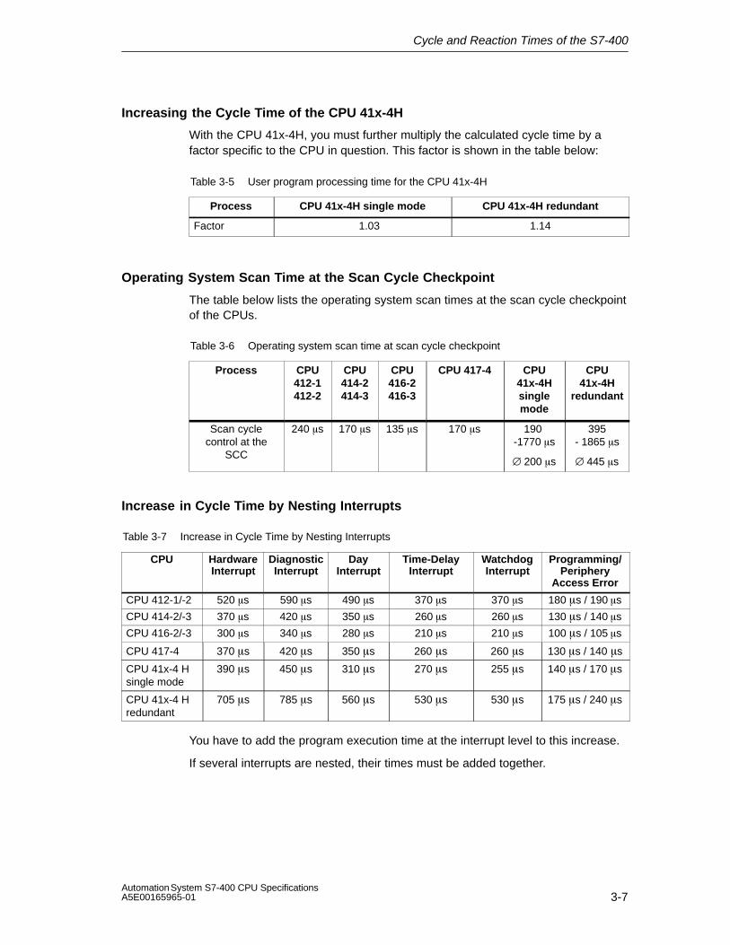
Cycle and Reaction Times of the S7-400
3-7Automation System S7-400 CPU SpecificationsA5E00165965-01
Increasing the Cycle Time of the CPU 41x-4H
With the CPU 41x-4H, you must further multiply the calculated cycle time by afactor specific to the CPU in question. This factor is shown in the table below:
Table 3-5 User program processing time for the CPU 41x-4H
Process CPU 41x-4H single mode CPU 41x-4H redundant
Factor 1.03 1.14
Operating System Scan Time at the Scan Cycle Checkpoint
The table below lists the operating system scan times at the scan cycle checkpointof the CPUs.
Table 3-6 Operating system scan time at scan cycle checkpoint
Process CPU412-1412-2
CPU414-2414-3
CPU416-2416-3
CPU 417-4 CPU41x-4Hsinglemode
CPU41x-4H
redundant
Scan cyclecontrol at the
SCC
240 �s 170 �s 135 �s 170 �s 190 -1770 �s
∅ 200 �s
395- 1865 �s
∅ 445 �s
Increase in Cycle Time by Nesting Interrupts
Table 3-7 Increase in Cycle Time by Nesting Interrupts
CPU HardwareInterrupt
DiagnosticInterrupt
DayInterrupt
Time-DelayInterrupt
WatchdogInterrupt
Programming/Periphery
Access Error
CPU 412-1/-2 520 �s 590 �s 490 �s 370 �s 370 �s 180 �s / 190 �s
CPU 414-2/-3 370 �s 420 �s 350 �s 260 �s 260 �s 130 �s / 140 �s
CPU 416-2/-3 300 �s 340 �s 280 �s 210 �s 210 �s 100 �s / 105 �s
CPU 417-4 370 �s 420 �s 350 �s 260 �s 260 �s 130 �s / 140 �s
CPU 41x-4 Hsingle mode
390 �s 450 �s 310 �s 270 �s 255 �s 140 �s / 170 �s
CPU 41x-4 Hredundant
705 �s 785 �s 560 �s 530 �s 530 �s 175 �s / 240 �s
You have to add the program execution time at the interrupt level to this increase.
If several interrupts are nested, their times must be added together.
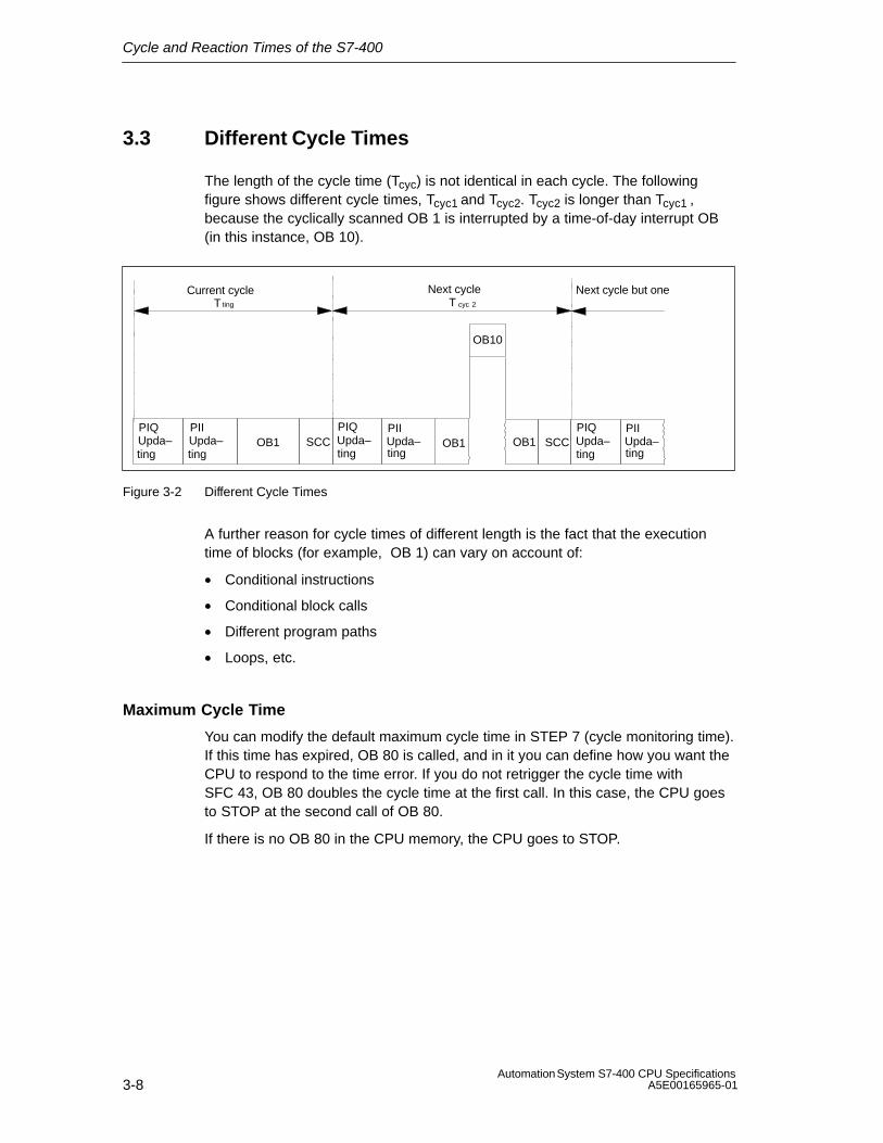
Cycle and Reaction Times of the S7-400
3-8Automation System S7-400 CPU Specifications
A5E00165965-01
3.3 Different Cycle Times
The length of the cycle time (Tcyc) is not identical in each cycle. The followingfigure shows different cycle times, Tcyc1 and Tcyc2. Tcyc2 is longer than Tcyc1 ,because the cyclically scanned OB 1 is interrupted by a time-of-day interrupt OB(in this instance, OB 10).
Current cycle Next cycle
OB10
T
OB1PIQUpda–
ting
ting
PIIUpda–ting
SCC OB1PIQUpda–ting
PIIUpda–ting
SCCOB1
cyc 2TNext cycle but one
PIQUpda–ting
PIIUpda–ting
Figure 3-2 Different Cycle Times
A further reason for cycle times of different length is the fact that the executiontime of blocks (for example, OB 1) can vary on account of:
• Conditional instructions
• Conditional block calls
• Different program paths
• Loops, etc.
Maximum Cycle Time
You can modify the default maximum cycle time in STEP 7 (cycle monitoring time).If this time has expired, OB 80 is called, and in it you can define how you want theCPU to respond to the time error. If you do not retrigger the cycle time withSFC 43, OB 80 doubles the cycle time at the first call. In this case, the CPU goesto STOP at the second call of OB 80.
If there is no OB 80 in the CPU memory, the CPU goes to STOP.

Cycle and Reaction Times of the S7-400
3-9Automation System S7-400 CPU SpecificationsA5E00165965-01
Minimum Cycle Time
You can set a minimum cycle time for a CPU in STEP 7. This is practical if
• you want the intervals of time between the start of program scanning of OB1(free cycle) to be roughly of the same length, or
• updating of the process images would be performed unnecessarily often withtoo short a cycle time, or
• you want to process a program with the OB 90 in the background (notCPU 41x-4H).
Current cycle Next cycle
OB10
OB40
T
Tmin
Tmax
Twait
OB1updatingof the outputs
updatingof the inputs
updatingof the outputs
OB90 OB90
Tmin
TcycTwait
Prupdof the
= the adjustable minimum cycle time
= the cycle time= the difference between Tmin and the actual cycle time; in this time, any interrupts that occur, the background OB and the SCC tasks can be processed.
cyc
Standby
PCl = priority class
PCl16
PCl07
PCl01
PCl29(=PCl0,29)
Tmax = the adjustable maximum cycle time
SCCOB1Process imageProcess image Process image
Figure 3-3 Minimum Cycle Time
The actual cycle time is the sum of Tcyc and Twait. It is always greater than or equalto Tmin.

Cycle and Reaction Times of the S7-400
3-10Automation System S7-400 CPU Specifications
A5E00165965-01
3.4 Communication Load
The CPU operating system continually makes available to communications thepercentage you configured for the overall CPU processing performance (timesharing). If this processing performance is not required for communications, it isavailable for other processing tasks.
In the hardware configuration, you can set the load due to communications tobetween 5% and 50%. By default, the value is set to 20%.
This percentage should be regarded as an average value, in other words, thecommunications component can be considerably greater than 20% in a time slice.On the other hand, the communications component in the next time slice is only afew or zero percent. This fact is also expressed by the following formula:
�������������������������������������������������������������������������������
������������ ������������������������
���������������
�������������
������������� ����������������������������� ��
Figure 3-4 Formula: Influence of Communication Load
Data consistency
The user program is interrupted for communications processing. The interrupt canbe executed after any instruction. These communication jobs can modify theprogram data.This means that the data consistency cannot be guaranteed for the duration ofseveral accesses.The manner in which you can guarantee consistency enduring for more than justone instruction is explained in the manual System Software for S7-300/400 Systemand Standard Functions, in the chapter on Overview of S7 Communications andS7 Basic Communications.
Time slice (1 ms)
User Program
Communication Functions
Operating system
Component configurablebetween 5 and 50%
Interrupt of theuser program
Figure 3-5 Breakdown of a Time Slice
Of the part remaining, the operating system of the S7-400 requires only anegligibly small amount for internal tasks. CPU 41x-4H is an exception: For H CPUs the operating system part is taken intoaccount in the factor specified in Table 3-5.

Cycle and Reaction Times of the S7-400
3-11Automation System S7-400 CPU SpecificationsA5E00165965-01
Example: 20 % Communication Load
You have configured a communication load of 20% in the hardware configuration.
The calculated cycle time is 10 ms.
A 20% communication load means that, on average, 200 �s and 800 �s of the timeslice remain for communications and the user program, respectively. The CPUtherefore requires 10 ms / 800 �s = 13 time slices to process one cycle. Thismeans that the actual cycle time is 13 times a 1 ms time slice = 13 ms, if the CPUfully utilizes the configured communication load.
This means that 20% communications do not increase the cycle linearly by 2 msbut by 3 ms.
Example: 50 % Communication Load
You have configured a communication load of 50% in the hardware configuration.
The calculated cycle time is 10 ms.
This means that 500 �s of each time slice remain for the cycle. The CPU thereforerequires 10 ms / 500 �s = 20 time slices to process one cycle. This means thatthe actual cycle time is 20 ms if the CPU fully utilizes the configuredcommunication load.
A 50 % communication load means that, on average, 500 �s and 500 �s of thetime slice remain for communications and the user program, respectively. The CPUtherefore requires 10 ms / 500 �s = 20 time slices to process one cycle. Thismeans that the actual cycle time is 20 times a 1 ms time slice = 20 ms, if the CPUfully utilizes the configured communication load.
This means that 50% communications do not increase the cycle linearly by 5 msbut by 10 ms.

Cycle and Reaction Times of the S7-400
3-12Automation System S7-400 CPU Specifications
A5E00165965-01
Dependency of the Actual Cycle Time on the Communication Load
The following figure describes the non-linear dependency of the actual cycle timeon the communication load. As an example, we have chosen a cycle time of10 ms.
You can set the communication load in thisrange
0% 10% 20% 30% 40% 50% 60%Communication load
Cycletime
10 ms
20 ms
25 ms
15 ms
5 ms
30 ms
5%
Figure 3-6 Dependency of the Cycle Time on the Communication Load
Further Effect on the Actual Cycle Time
Due to the increase in the cycle time as a result of the communicationscomponent, even more asynchronous events occur, from a statistical point of view,within an OB 1 cycle than, say, interrupts. This also increases the OB 1 cycle. Thisincrease depends on how many events occur per OB 1 cycle and how long eventprocessing lasts.
Notes
• Check the effects of a change of the value for the parameter “Cycle load due tocommunications” in system operation.
• The communication load must be taken into account when you set themaximum cycle time, since time errors will occur if it is not.
Recommendations
• If possible, apply the default value.
• Use a larger value only if the CPU is being used primarily for communicationpurposes and the user program is non-time-critical. In all other cases select asmaller value.

Cycle and Reaction Times of the S7-400
3-13Automation System S7-400 CPU SpecificationsA5E00165965-01
3.5 Reaction Time
Definition of the Reaction Time
The reaction time is the time from an input signal being detected to changing anoutput signal linked to it.
Variation
The actual reaction time is somewhere between a shortest and a longest reactiontime. For configuring your system, you must always reckon with the longestreaction time.
The shortest and longest reaction times are analyzed below so that you can gainan impression of the variation of the reaction time.
Factors
The reaction time depends on the cycle time and on the following factors:
• Delay in the inputs and outputs
• Additional DP cycle times on the PROFIBUS-DP network
• Execution of the user program
Delay in the Inputs and Outputs
Depending on the module, you must heed the following time delays:
• For digital inputs: the input delay
• For interrupt-capable digital inputs: the input delay +the module-internal preparation time
• For digital outputs: negligible time delays
• For relay outputs: typical time delays from 10 to 20 ms.The delay of the relay outputs depends, among other things, on the temperature and voltage.
• For analog inputs: cycle time of analog input module
• For analog outputs: response time of the analog output module
The time delays can be found in the technical specifications of the signal modules.

Cycle and Reaction Times of the S7-400
3-14Automation System S7-400 CPU Specifications
A5E00165965-01
DP Cycle Times on the PROFIBUS-DP Network
If you have configured your PROFIBUS-DP network with STEP 7, then STEP 7 willcalculate the typical DP cycle time that must be expected. You can then have theDP cycle time of your configuration displayed for the bus parameters on theprogramming device.
The following figure will provide you with an overview of the DP cycle time. Weassume in this example that each DP slave has 4 byte of data on average.
Number of DP slaves
6 ms
4 ms
2 ms
1 2 4 8 16 32
Baud Rate: 12Mbps
Baud Rate: 1.5 Mbps
1 ms
Typ. 3 ms
5 ms
7 ms
Min. slaveinterval
64
Bustransittime
17 ms
Figure 3-7DP Cycle Times on the PROFIBUS-DP Network
If you are operating a PROFIBUS-DP network with more than one master, youmust take the DP cycle time into account for each master. In other words, performa separate calculation for each master and add the results together.

Cycle and Reaction Times of the S7-400
3-15Automation System S7-400 CPU SpecificationsA5E00165965-01
Shortest Reaction Time
The following figure illustrates the conditions under which the shortest reactiontime is achieved.
Immediately before the PII is read in, the status of the input underreview changes. The change of input signal is also taken into accountin the PII.
The change of input signal is processed here by the user program.
The reaction of the user program to the change of input signal is outputhere to the outputs.
Rea
ctio
n T
ime
Delay of the inputs
Delay of the outputs
SCC (OS)
User program
PII
PIQ
PIQ
SCC (OS)
Figure 3-8 Shortest Reaction Time
Calculation
The (shortest) reaction time is made up as follows:
• 1 × process image transfer time of the inputs +
• 1 × process image transfer time of the outputs +
• 1 × program processing time +
• 1 × operating system processing time at SCC +
• Delay in the inputs and outputs
This is equivalent to the sum of the cycle time and the delay in the inputs andoutputs.
Note
If the CPU and signal module are not in the central rack, you have to add doublethe runtime of the DP slave frame (including processing in the DP master).

Cycle and Reaction Times of the S7-400
3-16Automation System S7-400 CPU Specifications
A5E00165965-01
Longest Reaction Time
The following figure shows you how the longest reaction time results.
While the PII is being read in, the status of the inputunder review changes. The change of input signal is nolonger taken into account in the PII.
Here the change of input signal is taken into accountin the PII.
The change of input signal is processed here by theuser program.
The reaction of the user program to the change of inputsignal is passed here to the outputs.
Rea
ctio
n T
ime
Delay in the inputs+ DP cycle time on the PROFIBUS-DP
Delay in the outputs+ DP cycle time on the PROFIBUS-DP
SCC (OS)
User program
PII
PIQ
PIQ
SCC (OS)
SCC (OS)
User program
PII
PIQ
Figure 3-9 Longest Reaction Time
Calculation
The (longest) reaction time is made up as follows:
• 2 × process image transfer time of the inputs +
• 2 × process image transfer time of the outputs +
• 2 × operating system processing time +
• 2 × program processing time +
• 2 × runtime of the DP slave frame (including processing in the DP master) +
• Delay in the inputs and outputs
This is equivalent to the sum of twice the cycle time and the delay in the inputs andoutputs plus twice the DP cycle time.
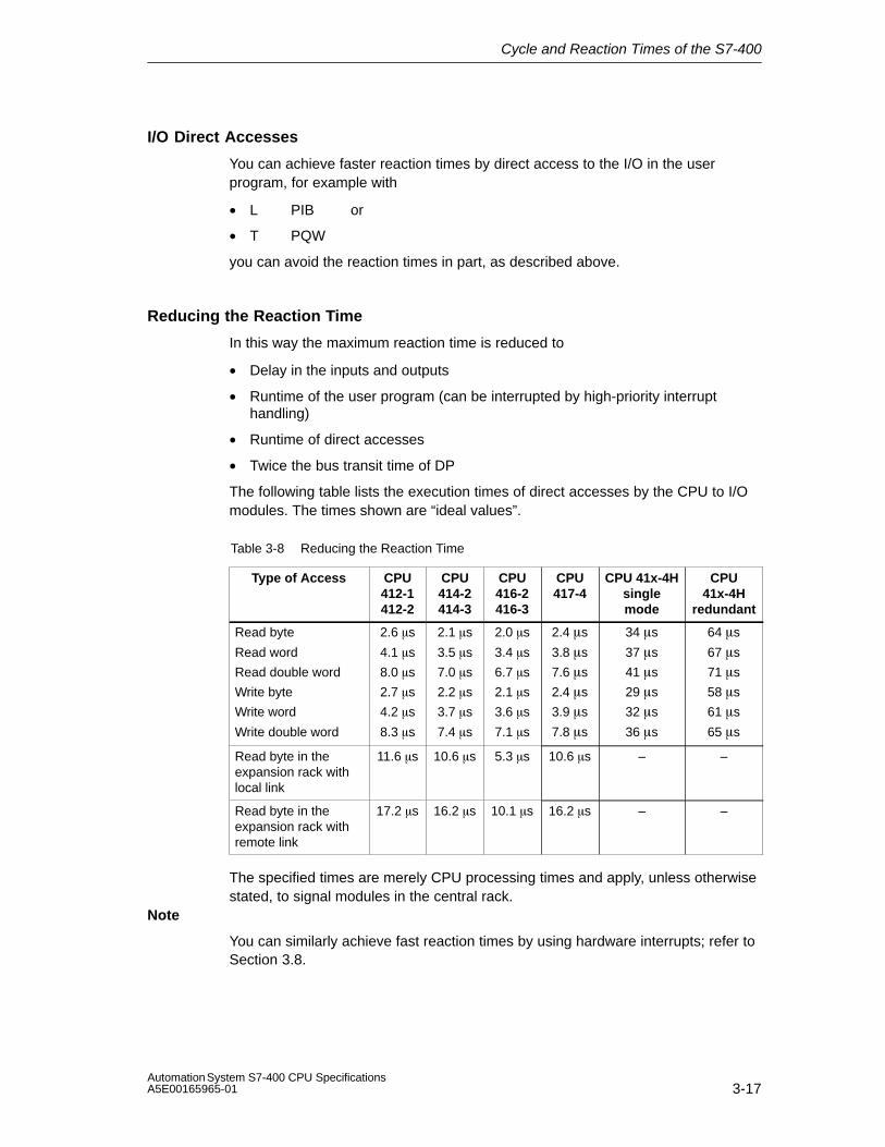
Cycle and Reaction Times of the S7-400
3-17Automation System S7-400 CPU SpecificationsA5E00165965-01
I/O Direct Accesses
You can achieve faster reaction times by direct access to the I/O in the userprogram, for example with
• L PIB or
• T PQW
you can avoid the reaction times in part, as described above.
Reducing the Reaction Time
In this way the maximum reaction time is reduced to
• Delay in the inputs and outputs
• Runtime of the user program (can be interrupted by high-priority interrupthandling)
• Runtime of direct accesses
• Twice the bus transit time of DP
The following table lists the execution times of direct accesses by the CPU to I/Omodules. The times shown are “ideal values”.
Table 3-8 Reducing the Reaction Time
Type of Access CPU412-1412-2
CPU414-2414-3
CPU416-2416-3
CPU417-4
CPU 41x-4Hsinglemode
CPU41x-4H
redundant
Read byte
Read word
Read double word
Write byte
Write word
Write double word
2.6 �s
4.1 �s
8.0 �s
2.7 �s
4.2 �s
8.3 �s
2.1 �s
3.5 �s
7.0 �s
2.2 �s
3.7 �s
7.4 �s
2.0 �s
3.4 �s
6.7 �s
2.1 �s
3.6 �s
7.1 �s
2.4 �s
3.8 �s
7.6 �s
2.4 �s
3.9 �s
7.8 �s
34 �s
37 �s
41 �s
29 �s
32 �s
36 �s
64 �s
67 �s
71 �s
58 �s
61 �s
65 �s
Read byte in theexpansion rack withlocal link
11.6 �s 10.6 �s 5.3 �s 10.6 �s – –
Read byte in theexpansion rack withremote link
17.2 �s 16.2 �s 10.1 �s 16.2 �s – –
The specified times are merely CPU processing times and apply, unless otherwisestated, to signal modules in the central rack.
Note
You can similarly achieve fast reaction times by using hardware interrupts; refer toSection 3.8.

Cycle and Reaction Times of the S7-400
3-18Automation System S7-400 CPU Specifications
A5E00165965-01
3.6 How Cycle and Reaction Times Are Calculated
Cycle time
1. Using the Instruction List, determine the runtime of the user program.
2. Calculate and add the transfer time for the process image. You will find guidevalues for this in Table 3-3.
3. Add to it the processing time at the scan cycle checkpoint. You will find guidevalues for this in Table 3-6.
4. CPU 417-4H: Multiply the calculated value by the factor in Table 3-5.
The result you achieve is the cycle time.
Increasing the Cycle Time with Communication and Interrupts
5. Multiply the result by the following factor:
100 100 - “configured communication load in %”
6. Using the Instruction List, calculate the runtime of the program sections thathardware interrupts. Add to it the relevant value in Table 3-7. Multiply this value by the factor from step 4.Add this value to the theoretical cycle time as often as the interrupt is triggeredor is expected to be triggered during the cycle time.
The result you obtain is approximately the actual cycle time. Make a note of theresult.
Table 3-9 Example of Calculating the Reaction Time
Shortest Reaction Time Longest Reaction Time
7. Then, calculate the delays in theinputs and outputs and, if applicable,
7. Multiply the actual cycle time by afactor of 2.
the DP cycle times on the PROFIBUSDP network.
8. Then, calculate the delays in theinputs and outputs and the DP cycletimes on the PROFIBUS DP network.
8. The result you obtain is the shortestreaction time.
9. The result you obtain is the longestreaction time.

Cycle and Reaction Times of the S7-400
3-19Automation System S7-400 CPU SpecificationsA5E00165965-01
3.7 Examples of Calculating the Cycle Time and ReactionTime
Example I
You have installed an S7-400 with the following modules in the central rack:
• One CPU 414-2
• Two digital input modules SM 421; DI 32×DC 24 V (4 byte each in PA)
• Two digital output modules SM 422; DO 32×DC 24 V/0.5A (4 byte each in PA)
User Program
According to the Instruction List, your user program has a runtime of 15 ms.
Cycle Time Calculation
The cycle time for the example results from the following times:
• Since the CPU-specific factor is 1.0, the user program processing time remains:
approx. 15.0 ms
• Process image transfer time
Process image: 20 �s + 16 byte×1.9 �s = approx. 0.05 ms
• Operating system runtime at scan cycle checkpoint: approx. 0.17 ms
The cycle time for the example results from the sum of the times listed:
Cycle time = 15.0 ms + 0.05 ms + 0.17 ms = 15.22 ms.
Calculation of the Actual Cycle Time
• Allowance of the communication load (default value: 20%): 15.22 ms * 100 / (100-20) = 19.03 ms.
• There is no interrupt handling.
Rounded off, the actual cycle time is thus 19 ms.

Cycle and Reaction Times of the S7-400
3-20Automation System S7-400 CPU Specifications
A5E00165965-01
Calculation of the Longest Reaction Time
• Longest reaction time 19.03 ms * 2 = 38.06 ms.
• The delay in the inputs and outputs is negligible.
• All the components are plugged into the central rack; DP cycle times do nottherefore have to be taken into account.
• There is no interrupt handling.
Rounded off, the longest reaction time is thus = 38 ms.
Example II
You have installed an S7-400 with the following modules:
• One CPU 414-2
• Four digital input modules SM 421; DI 32×DC 24 V (4 byte each in PA)
• Three digital output modules SM 422; DO 16×DC 24 V/2A (2 byte each in PA)
• Two analog input modules SM 431; AI 8×13 bit (not in PA)
• Two analog output modules SM 432; AO 8×13 bit (not in PA)
CPU Parameters
The CPU has been assigned parameters as follows:
• Cycle load due to communications: 40%
User Program
According to the Instruction List, the user program has a runtime of 10.0 ms.
Cycle Time Calculation
The theoretical cycle time for the example results from the following times:
• Since the CPU-specific factor is 1.0, the user program processing time remains:
approx. 10.0 ms
• Process image transfer time
Process image: 20 �s + 22 byte×1.9 �s = approx. 0.06 ms
• Operating system runtime at scan cycle checkpoint: approx. 0.17 ms
The cycle time for the example results from the sum of the times listed:
Cycle time = 10.0 ms + 0.06 ms + 0.17 ms = 10.23 ms.

Cycle and Reaction Times of the S7-400
3-21Automation System S7-400 CPU SpecificationsA5E00165965-01
Calculation of the Actual Cycle Time
• Allowance of communication load: 10.23 ms * 100 / (100-40) = 17.05 ms.
• A time-of-day interrupt having a runtime of 0.5 ms is triggered every 100 ms.The interrupt cannot be triggered more than once during a cycle:
0.5 ms + 0.35 ms (in Table 3-7) = 0.85 ms.Allowance for communication load:
0.85 ms * 100 / (100-40) = 1.42 ms.
• 17.05 ms + 1.42 ms = 18.47 ms.
The actual cycle time is therefore 19 ms taking into account the time slices.
Calculation of the Longest Reaction Time
• Longest reaction time 19 ms * 2 = 38 ms.
• Delays in the inputs and outputs
– The digital input module SM 421; DI 32×DC 24 V has an input delay of notmore than 4,8 ms per channel
– The digital output module SM 422; DO 16×DC 24 V/2A has a negligibleoutput delay.
– The analog input module SM 431; AI 8×13 bit was assigned parameters for50 Hz interference frequency suppression. This results in a conversion timeof 25 ms per channel. Since 8 channels are active, a cycle time of 200 msresults for the analog input module.
– Analog output module SM 432; AO 8×13 bit was assigned parameters forthe measuring range from 0 to 10V. This results in a conversion time of 0.3ms per channel. Since 8 channels are active, a cycle time of 2.4 ms results.To this must be added the settling time for the resistive load, which is 0.1ms. A response time of 2.5 ms therefore results for an analog output.
• All the components are plugged into the central rack; DP cycle times do nottherefore have to be taken into account.
• Case 1: When a digital signal is read in, an output channel of the digital outputmodule is set. This produces a reaction time of:
Reaction time= 38 ms + 4.8 ms = 42.8 ms.
• Case 2: An analog value is read in and an analog value output. This produces areaction time of:
Reaction time = 38 ms + 200 ms + 2.5 ms = 240.5 ms.

Cycle and Reaction Times of the S7-400
3-22Automation System S7-400 CPU Specifications
A5E00165965-01
3.8 Interrupt Reaction Time
Definition of the Interrupt Reaction Time
The interrupt reaction time is the time from when an interrupt signal first occurs tocalling the first instruction in the interrupt OB.
The following general rule applies: Interrupts having a higher priority takeprecedence. This means that the interrupt reaction time is increased by theprogram processing time of the higher priority interrupt OBs and interrupt OBs withthe same priority that have not yet been processed (queue).
NoteThe interrupt reaction times can be delayed by read and write jobs with a highdata volume (approx. 460 byte).When interrupts are transferred between a CPU and DP master, only a diagnosticor hardware interrupt can be currently reported at any time from a DP line.
Calculation
Min. interrupt reaction time of the CPU+ min. interrupt reaction time of the
signal modules+ DP cycle time on PROFIBUS-DP
= Shortest Reaction Time
Max. interrupt reaction time of the CPU + max. interrupt reaction time of the
signal modules+ 2 * DP cycle time on PROFIBUS-DP
= Longest Reaction Time
Figure 3-10 Calculating the Interrupt Reaction Time
Hardware Interrupt and Diagnostic Interrupt Reaction Times of CPUs
Table 3-10 Hardware Interrupt and Diagnostic Interrupt Reaction Times; Maximum InterruptReaction Time Without Communication
CPU Hardware InterruptReaction Times
Diagnostic Interrupt Reaction Times
Min. Max. Min. Max.
412-1/-2 360 �s 610 �s 440 �s 690 �s
414-2/-3 255 �s 435 �s 310 �s 490 �s
416-2/-3 210 �s 350 �s 250 �s 400 �s
417-4 255 �s 435 �s 310 �s 490 �s
41x-4H single mode 270 �s 530 �s 325 �s 645 �s
41x-4H redundant 375 �s 690 �s 415 �s 780 �s

Cycle and Reaction Times of the S7-400
3-23Automation System S7-400 CPU SpecificationsA5E00165965-01
Increasing the Maximum Interrupt Reaction Time with Communication
The maximum interrupt reaction time increases when communication functions areactive. The increase is calculated with the following formula:
CPU 412: tv = 200 �s + 1000 �s × n%
CPU 414-417: tv = 100 �s + 1000 �s × n%
CPU 41x-4H tv = 100 �s + 1000 �s × n%, considerable more time possible
where n = cycle load from communication
Signal Modules
The hardware interrupt reaction time of the signal modules is made up as follows:
• Digital input modules
Hardware interrupt reaction time = internal interrupt processing time + inputdelay
You will find the times in the data sheet of the digital input module concerned.
• Analog input modules
Hardware interrupt reaction time = internal interrupt processing time +conversion time
The internal interrupt processing time of the analog input modules is negligible.The conversion times can be taken from the data sheet of the analog inputmodule concerned.
The diagnostic interrupt reaction time of the signal modules is the time whichelapses between a diagnostics event being detected by the signal module and thediagnostic interrupt being triggered by the signal module. This time is so small thatit can be ignored.
Hardware Interrupt Processing
When the hardware interrupt OB 40 is called, the hardware interrupt is processed.Interrupts with higher priority interrupt hardware interrupt processing, and directaccess to the I/O is made when the instruction is executed. When hardwareinterrupt processing is completed, either cyclic program processing is continued orother interrupt OBs with the same or a lower priority are called and processed.

Cycle and Reaction Times of the S7-400
3-24Automation System S7-400 CPU Specifications
A5E00165965-01
3.9 Example of Calculating the Interrupt Reaction Time
Parts of the Interrupt Reaction Time
As a reminder, the hardware interrupt reaction time is made up of the following:
• Hardware interrupt reaction time of the CPU
• Hardware interrupt reaction time of the signal module.
• 2 × DP cycle time on the PROFIBUS-DP
Example: You have an S7-400 consisting of a CPU 416-2 and 4 digital modules inthe central rack. One digital input module is the SM 421; DI 16×UC 24/60 V; withhardware and diagnostic interrupts. In the parameter assignment of the CPU andthe SM, you have only enabled the hardware interrupt. You do not requiretime-driven processing, diagnostics and error handling. You have assigned an inputdelay of 0.5 ms for the digital input module. No activities at the scan cyclecheckpoint are required. You have set a cycle load from communication of 20%.
Calculation
The hardware interrupt reaction time for the example results from the followingtimes:
• Hardware interrupt reaction time of the CPU 416-2: approx. 0.35 ms
• Increase from communication in accordance with the formula shown in thefootnote of Table 3-10 :
100 �s + 1000 �s × 20% = 300 �s = 0.3 ms
• Hardware interrupt reaction time of the SM 421; DI 16×UC 24/60 V:
– Internal interrupt processing time: 0.5 ms
– Input delay: 0.5 ms
• Since the signal modules are plugged into the central rack, the DP cycle timeon the PROFIBUS-DP is not relevant.
The hardware interrupt reaction time results from the sum of the listed times:
Hardware interrupt reaction time = 0.35 ms +0.3 ms + 0.5 ms + 0.5 ms = approx.1.65 ms.
This calculated hardware interrupt reaction time is the time from a signal beingapplied across the digital input to the first instruction in OB 40.

Cycle and Reaction Times of the S7-400
3-25Automation System S7-400 CPU SpecificationsA5E00165965-01
3.10 Reproducibility of Time-Delay and Watchdog Interrupts
Definition of “Reproducibility”
Time-delay interrupt:
The deviation with time from the first instruction of the interrupt OB being called tothe programmed interrupt time.
Watchdog interrupt
The variation in the time interval between two successive calls, measures betweenthe first instruction of the interrupt OB in each case.
Reproducibility
Table 3-11 contains the reproducibility of time-delay and watchdog interrupts of theCPUs.
Table 3-11 Reproducibility of Time-Delay and Watchdog Interrupts of theCPUs.
Baugruppe Reproducibility
Time-Delay Interrupt: Watchdog Interrupt
CPU 412-1/-2 –770 �s / +330 �s –40 �s / +40 �s
CPU 414-2/-3 –770 �s / +330 �s –40 �s / +40 �s
CPU 416-2/-3 –770 �s / +330 �s –40 �s / +40 �s
CPU 417-4 –770 �s / +330 �s –40 �s / +40 �s
CPU 41x-4H single mode
–750 �s / +400 �s –850 �s / +850 �s
CPU 41x-4H redundant –500 �s / +800 �s –700 �s / +700 �s
These times apply only if the interrupt can be executed at this time and not, forexample, delayed by interrupts with higher priority or interrupts of identical prioritythat have not yet been executed.

Cycle and Reaction Times of the S7-400
3-26Automation System S7-400 CPU Specifications
A5E00165965-01

4-1Automation System S7-400 CPU SpecificationsA5E00165965-01
Technical Specifications
Chapter overview
In Section You Will Find On Page
4.1 Technical Specifications of the CPU 412-1;(6ES7412-1XF03-0AB0)
4-2
4.2 Technical Specifications of the CPU 412-2;(6ES7412-2XG00-0AB0)
4-6
4.3 Technical Specifications of the CPU 414-2;(6ES7414-2XG03-0AB0)
4-10
4.4 Technical Specifications of the CPU 414-3;(6ES7414-3XJ00-0AB0)
4-14
4.5 Technical Specifications of the CPU 416-2; (6ES7416-2XK02-0AB0, 6ES7416-2FK02-0AB0)
4-18
4.6 Technical Specifications of the CPU 416-3;(6ES7416-3XL00-0AB0)
4-22
4.7 Technical Specifications of the CPU 417-4;(6ES7417-4XL00-0AB0)
4-26
4.8 Technical Specifications of the Memory Cards 4-30
4

Technical Specifications
4-2Automation System S7-400 CPU Specifications
A5E00165965-01
4.1 Technical Specifications of the CPU 412-1; (6ES7412-1XF03-0AB0)
CPU and VersionMLFB 6ES7412-1XF03-0AB0
• Firmware version V 3.1
Associated programmingpackage
As of STEP7 V 5.2
Memory
Working memory
• Integrated 48 Kbytes for code48 Kbytes for data
• Expandable No
Load memory
• Integrated 256 Kbytes RAM
• Expandable FEPROM With memory card(FLASH) up to 64 Mbytes
• Expandable RAM With memory card (RAM)up to 64 Mbytes
Backup Yes
• With battery All data
• Without battery None
Processing Times
Processing times for
• Bit operations Min. 0.2 �s
• Word instructions Min. 0.2 �s
• Integer math instructions Min. 0.2 �s
• Floating-point mathinstructions
Min. 0.6 �s
Timers/Counters and Their RetentivityS7 counters 256
• Retentivity can be set From Z 0 to Z 255
• Preset From Z 0 to Z 7
• Counting range 1 to 999
IEC counter Yes
• Type SFB
S7 timers 256
• Retentivity can be set From T 0 to T 255
• Preset No retentive timers
• Time range 10 ms to 9990 s
IEC timers Yes
• Type SFB
Data Areas and Their RetentivityTotal retentive data areas(including memory bits;times; counts)
Total working and loadmemory (with backupbattery)
Memory markers 4 Kbytes
• Retentivity can be set From MB 0 to MB 4095
• Preset retentivity From MB 0 to MB 15
Clock memories 8 (1 memory byte)
Data blocks Max. 511 (DB 0 reserved)
• Size Max. 48 Kbytes
Local data (can be set) Max. 8 Kbytes
• Preset 4 Kbytes
Blocks
OBs See instruction list
• Size Max. 48 Kbytes
Nesting depth
• Per priority class 24
• Additionally in an errorOB
2
FBs Max. 256
• Size Max. 48 Kbytes
FCs Max. 256
• Size Max. 48 Kbytes
Address Areas (Inputs/Outputs)
Total I/O address area 4 Kbytes/4 Kbytes
• Of which distributed
MPI/DP interface 2 Kbytes/2 Kbytes
The distributed I/O address area is halved for each strandoperated clock synchronously, i.e. in which an OB 61 isassigned.
Process Image 4 Kbytes/4 Kbytes (canbe set)
• Preset 128 bytes/128 bytes
• Number of partialprocess images
Max. 8
• Consistent data Max. 244 bytes
Digital channels 32768/32768
• Of which central 32768/32768
Analog channels 2048/2048
• Of which central 2048/2048

Technical Specifications
4-3Automation System S7-400 CPU SpecificationsA5E00165965-01
ConfigurationCentral racks/expansionunits
Max. 1/21
Multicomputing Max. 4 CPUs (with UR1 or UR2)
Number of plug-in IMs(overall)
Max. 6
• IM 460 Max. 6
• IM 463-2 Max. 4
Number of DP masters
• Integrated 1
• Via IM 467 Max. 4
• Via CP Max. 10
IM 467 cannot be used with the CP 443-5 Extended
Number of plug-in S5modules via adapter casing(in the central rack)
Max. 6
Operable function modulesand communicationprocessors
• FM Limited by the number ofslots and the number ofconnections
• CP 440 Limited by the number ofslots
• CP 441 Limited by the number ofconnections
• PROFIBUS and EthernetCPs incl. CP 443-5Extended and IM 467
Max. 14
Time
Clock Yes
• Buffered Yes
• Resolution 1 ms
• Accuracy at
– Power off Deviation per day 1.7 s
– Power on Deviation per day 8.6 s
Runtime meter 8
• Number 0 to 7
• Value Range 0 to 32767 hours
• Granularity 1 hour
• Retentive Yes
Time synchronization Yes
• In PLC, on MPI and DP as master or slave
Time of day difference in thesystem for synchronizationvia
• ETHERNET maximum 10 ms
• MPI maximum 200 ms
S7 Message FunctionsNumber of stations that canlog on for messagefunctions (e.g. WIN CC orSIMATIC OP)
Max. 8
Symbol-related messages Yes
• Number of messages
– Overall
– 100 ms grid
– 500 ms grid
– 1000 ms grid
Max. 512
None
Max. 256
Max. 256
• Number of additionalvalues per message
1
– With 100 ms grid None
– With 500, 1000 msgrid
1
Block-related messages Yes
• Simultaneously activeALARM-S/SQ blocksand ALARM-D/DQblocks
Max. 70
ALARM-8 blocks Yes
• Number ofcommunication jobs forALARM-8 blocks andblocks for S7communication (can beset)
Max. 300
• Preset 150
Process control reports Yes
Number of archives thatcan log on simultaneously(SFB 37 AR_SEND)
4
Test and Startup Functions
Monitor/modify variable Yes
• Variables Inputs/outputs, memorymarkers, DB, distributedinputs/outputs, timers,counters
• Number of variables Max. 70
Force Yes
• Variables Inputs/outputs, memorymarkers, distributedinputs/outputs
• Number of variables Max. 64
Status block Yes
Single sequence Yes
Diagnostic buffer Yes
• Number of entries Max. 200 (can be set)
• Preset 120
Number of breakpoints 4

Technical Specifications
4-4Automation System S7-400 CPU Specifications
A5E00165965-01
Communication FunctionsProgramming device/OPcommunication
Yes
Number of connectableOPs
16 without messageprocessing, 8 with messageprocessing
Number of connectionresources for S7connections via allinterfaces and CPs
16, with each of themreserved for PG andOPrespectively
Global data communication Yes
• Number of GD circuits Max. 8
• Number of GDpackages
– Sender Max. 8
– Receiver Max. 16
• Size of GD packages Max. 64 bytes
– Of which consistent 1 variable
S7 basic communication Yes
• User data per job Max. 76 bytes
– Of which consistent 16 bytes
S7 communication Yes
• User data per job Max. 64 Kbytes
– Of which consistent 1 variable (462 bytes)
S5-compatiblecommunication
Yes (via CP – max. 10 –and FC AG_SEND andAG_RECV)
• User data per job Max. 8 Kbytes
– Of which consistent 240 bytes
Standard communication(FMS)
Yes (via CP and loadableFB)
Interfaces1st Interface
Type of interface Integrated
Physical RS 485/Profibus
Isolated Yes
Power supply to interface(15 VDC to 30 VDC)
Max. 150 mA
Number of connectionresources
MPI: 16DP: 16
Functionality
• MPI Yes
• PROFIBUS DP DP master/DP slave
MPI• Utilities
– Programmingdevice/OPcommunication
Yes
– Routing Yes
– Global datacommunication
Yes
– S7 basiccommunication
Yes
– S7 communication Yes
• Transmission rates Up to 12 Mbps
DP Master
• Utilities
– Programmingdevice/OPcommunication
Yes
– Routing Yes
– Constant bus cycletime
Yes
– SYNC/FREEZE Yes
– Enable/disable DPslaves
Yes
• Transmission rates Up to 12 Mbps
• Number of DP slaves Max. 32
• Address area Max. 2 Kbytes inputs/2Kbytes outputs
• User data per DP slave Maximum 244 bytes E,maximum 244 bytes A,distributed over 244 slotseach with 128 bytes
DP slave
• Utilities
– Monitor/modify
– Programming
– Routing
Yes, if the interface is active
Yes, if the interface is active
Yes, if the interface is active
• DDB (GSD) file http://www.ad.siemens.de/csi_e/gsd
• Transmission rate Up to 12 Mbps
• Intermediate memory 244 bytes inputs/244 bytes outputs
– Address areas
– User data peraddress area
– Of which consistent
Max. 32
Max. 32 bytes
32 bytes

Technical Specifications
4-5Automation System S7-400 CPU SpecificationsA5E00165965-01
ProgrammingProgramming language LAD, FBD, STL, SCL
Instruction set See instruction list
Bracket levels 8
System functions (SFC) See instruction list
Number of SFCs active atthe same time
• WR_REC 8
• WR_PARM 8
• PARM_MOD 1
• WR_DPARM 2
• DPNRM_DG 8
• RDSYSST 1 to 8
• DP_TOPOL 1
System function blocks(SFB)
See instruction list
Number of SFBs active atthe same time
• RD_REC 8
• WR_REC 8
User program protection Password protection
Access to consistent datain the process image
Yes
Clock synchronism
User data per clocksynchronous slave
Max. 128 bytes
Maximum number of bytesand slaves in a processimage partition
The following applies:
Number of bytes / 100 +number of slaves < 11
Equidistance Yes
Shortest clock pulse 5 ms
2.5 ms without use of SFC126, 127
CiR synchronization time
Base load 100 ms
Time per I/O byte 200 µs
DimensionsMounting dimensionsW×H×D (mm)
25×290×219
Slots required 1
Weight Approx. 0.72 kg
Voltages, Currents
Current consumption fromS7-400 bus (5 VDC)
Typ. 1.5 A
Max. 1.6 A
Current consumption fromthe S7-400 bus (24 VDC)The CPU does notconsume any current at24 V, and it only makes thisvoltage available at theMPI/DP interface.
Total current consumptionof the componentsconnected to the MPI/DPinterfaces, with a maximumof 150 mA per interface
Backup current Typ. 40 �A
Max. 300 �A
maximum backup time approx 356 days
Incoming supply of externalbackup voltage to the CPU
5 VDC to 15 VDC
Power loss Typ. 7.5 W

Technical Specifications
4-6Automation System S7-400 CPU Specifications
A5E00165965-01
4.2 Technical Specifications of the CPU 412-2; (6ES7412-2XG00-0AB0)
CPU and VersionMLFB 6ES7412-2XG00-0AB0
• Firmware version V 3.1
Associated programmingpackage
As of STEP7 V 5.2
Memory
Working memory
• Integrated 72 Kbytes for code
72 Kbytes for data
• Expandable No
Load memory
• Integrated 256 Kbytes RAM
• Expandable FEPROM With memory card (FLASH)up to 64 Mbytes
• Expandable RAM With memory card (RAM)up to 64 Mbytes
Backup Yes
• With battery All data
• Without battery None
Processing Times
Processing times for
• Bit operations Min. 0.2 �s
• Word instructions Min. 0.2 �s
• Integer mathinstructions
Min. 0.2 �s
• Floating-point mathinstructions
Min. 0.6 �s
Timers/Counters and Their RetentivityS7 counters 256
• Retentivity can be set From Z 0 to Z 255
• Preset From Z 0 to Z 7
• Counting range 1 to 999
IEC counter Yes
• Type SFB
S7 timers 256
• Retentivity can be set From T 0 to T 255
• Preset No retentive timers
• Time range 10 ms to 9990 s
IEC timers Yes
• Type SFB
Data Areas and Their RetentivityTotal retentive data areas(including memory bits;times; counts)
Total working and loadmemory (with backupbattery)
Memory markers 4 Kbytes
• Retentivity can be set From MB 0 to MB 4095
• Preset retentivity From MB 0 to MB 15
Clock memories 8 (1 memory byte)
Data blocks Max. 511 (DB 0 reserved)
• Size Max. 64 Kbytes
Local data (can be set) Max. 8 Kbytes
• Preset 4 Kbytes
Blocks
OBs See instruction list
• Size Max. 64 Kbytes
Nesting depth
• Per priority class 24
• Additionally in an errorOB
2
FBs Max. 256
• Size Max. 64 Kbytes
FCs Max. 256
• Size Max. 64 Kbytes
Address Areas (Inputs/Outputs)
Total I/O address area 4 Kbytes/4 Kbytes
• Of which distributed
MPI/DP interface 2 Kbytes/2 Kbytes
DP interface 4 Kbytes/4 Kbytes
The distributed I/O address area is halved for each strandoperated clock synchronously, i.e. in which an OB 61/62is assigned.
Process Image 4 Kbytes/4 Kbytes (can beset)
• Preset 128 bytes/128 bytes
• Number of partialprocess images
Max. 8
• Consistent data Max. 244 bytes
Digital channels 32768/32768
• Of which central 32768/32768
Analog channels 2048/2048
• Of which central 2048/2048

Technical Specifications
4-7Automation System S7-400 CPU SpecificationsA5E00165965-01
ConfigurationCentral racks/expansionunits
Max. 1/21
Multicomputing Max. 4 CPUs (with UR1 or UR2)
Number of plug-in IMs(overall)
Max. 6
• IM 460 Max. 6
• IM 463-2 Max. 3
Number of DP masters
• Integrated 2
• Via IM 467 Max. 4
• Via CP Max. 10
IM 467 cannot be used with the CP 443-5 Extended
Number of plug-in S5modules via adapter casing(in the central rack)
Max. 6
Operable function modulesand communicationprocessors
• FM Limited by the number ofslots and the number ofconnections
• CP 440 Limited by the number ofslots
• CP 441 Limited by the number ofconnections
• Profibus and EthernetCPs incl. CP 443-5Extended and IM 467
Max. 14
Time
Clock Yes
• Buffered Yes
• Resolution 1 ms
• Accuracy at
– Power off Deviation per day 1.7 s
– Power on Deviation per day 8.6 s
Runtime meter 8
• Number 0 to 7
• Value Range 0 to 32767 hours
• Granularity 1 hour
• Retentive Yes
Time synchronization Yes
• In PLC, on MPI and DP as master or slave
Time of day difference inthe system forsynchronization via
• ETHERNET maximum 10 ms
• MPI maximum 200 ms
S7 Message FunctionsNumber of stations that canlog on for messagefunctions (e.g. WIN CC orSIMATIC OP)
Max. 8
Symbol-related messages Yes
• Number of messages
– Overall
– 100 ms grid
– 500 ms grid
– 1000 ms grid
Max. 512
None
Max. 256
Max. 256
• Number of additionalvalues per message
1
– With 100 ms grid None
– With 500, 1000 msgrid
1
Block-related messages Yes
• Simultaneously activeALARM-S/SQ blocksand ALARM-D/DQblocks
Max. 70
ALARM-8 blocks Yes
• Number ofcommunication jobs forALARM-8 blocks andblocks for S7communication (can beset)
Max. 300
• Preset 150
Process control reports Yes
Number of archives thatcan log on simultaneously(SFB 37 AR_SEND)
4
Test and Startup Functions
Monitor/modify variable Yes
• Variables Inputs/outputs, memorymarkers, DB, distributedinputs/outputs, timers,counters
• Number of variables Max. 70
Force Yes
• Variables Inputs/outputs, memorymarkers, distributedinputs/outputs
• Quantity Max. 64
Status block Yes
Single sequence Yes
Diagnostic buffer Yes
• Number of entries Max. 400 (can be set)
• Preset 120
Number of breakpoints 4

Technical Specifications
4-8Automation System S7-400 CPU Specifications
A5E00165965-01
Communication FunctionsProgramming device/OPcommunication
Yes
Number of connectableOPs
16 without messageprocessing, 8 with messageprocessing
Number of connectionresources for S7connections via allinterfaces and CPs
16, with one each of thosereserved for PG and OP
Global data communication Yes
• Number of GD circuits Max. 8
• Number of GDpackages
– Sender Max. 8
– Receiver Max. 16
• Size of GD packages Max. 64 bytes
– Of which consistent 1 variable
S7 basic communication Yes
• User data per job Max. 76 bytes
– Of which consistent 16 Byte
S7 communication Yes
• User data per job Max. 64 Kbytes
– Of which consistent 1 variable (462 bytes)
S5-compatiblecommunication
Yes (via CP – max. 10 –and FC AG_SEND and FCAG_RECV)
• User data per job Max. 8 Kbytes
– Of which consistent 240 bytes
Standard communication(FMS)
Yes (via CP and loadableFB)
Interfaces1st Interface
Type of interface Integrated
Physical RS 485/Profibus
Isolated Yes
Power supply to interface(15 VDC to 30 VDC)
Max. 150 mA
Number of connectionresources
MPI: 16DP: 16
Functionality
• MPI Yes
• PROFIBUS DP DP master/DP slave
MPI• Utilities
– Programmingdevice/OPcommunication
Yes
– Routing Yes
– Global datacommunication
Yes
– S7 basiccommunication
Yes
– S7 communication Yes
• Transmission rates Up to 12 Mbps
DP Master
• Utilities
– Programmingdevice/OPcommunication
Yes
– Routing Yes
– Equidistance Yes
– SYNC/FREEZE Yes
– Enable/disable DPslaves
Yes
• Transmission rates Up to 12 Mbps
• Number of DP slaves Max. 32
• Address area Max. 2 Kbytes inputs/2Kbytes outputs
• User data per DP slave Maximum 244 bytes E,maximum 244 bytes A,distributed over 244 slotseach with 128 bytes
DP slave
• Utilities
– Monitor/modify
– Programming
– Routing
Yes, if the interface is active
Yes, if the interface is active
Yes, if the interface is active
• DDB (GSD) file http://www.ad.siemens.de/csi_e/gsd
• Transmission rate Up to 12 Mbps
• Intermediate memory 244 bytes inputs/244 bytes outputs
– Address areas
– User data peraddress area
– Of which consistent
Max. 32
Max. 32 bytes
32 bytes
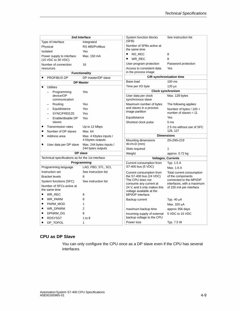
Technical Specifications
4-9Automation System S7-400 CPU SpecificationsA5E00165965-01
2nd InterfaceType of interface Integrated
Physical RS 485/Profibus
Isolated Yes
Power supply to interface(15 VDC to 30 VDC)
Max. 150 mA
Number of connectionresources
16
Functionality
• PROFIBUS DP DP master/DP slave
DP Master
• Utilities
– Programmingdevice/OPcommunication
Yes
– Routing Yes
– Equidistance Yes
– SYNC/FREEZE Yes
– Enable/disable DPslaves
Yes
• Transmission rates Up to 12 Mbps
• Number of DP slaves Max. 64
• Address area Max. 4 Kbytes inputs / 4 Kbytes outputs
• User data per DP slave Max. 244 bytes inputs /244 bytes outputs
DP slave
Technical specifications as for the 1st interface
ProgrammingProgramming language LAD, FBD, STL, SCL
Instruction set See instruction list
Bracket levels 8
System functions (SFC) See instruction list
Number of SFCs active atthe same time
• WR_REC 8
• WR_PARM 8
• PARM_MOD 1
• WR_DPARM 2
• DPNRM_DG 8
• RDSYSST 1 to 8
• DP_TOPOL 1
System function blocks(SFB)
See instruction list
Number of SFBs active atthe same time
• RD_REC 8
• WR_REC 8
User program protection Password protection
Access to consistent datain the process image
Yes
CiR synchronization time
Base load 100 ms
Time per I/O byte 120 µs
Clock synchronism
User data per clocksynchronous slave
Max. 128 bytes
Maximum number of bytesand slaves in a processimage partition
The following applies:
Number of bytes / 100 +number of slaves < 11
Equidistance Yes
Shortest clock pulse 5 ms
2.5 ms without use of SFC126, 127
Dimensions
Mounting dimensionsW×H×D (mm)
25×290×219
Slots required 1
Weight approx. 0.72 kg
Voltages, Currents
Current consumption fromS7-400 bus (5 VDC)
Typ. 1.5 A
Max. 1.6 A
Current consumption fromthe S7-400 bus (24 VDC)The CPU does notconsume any current at24 V, and it only makes thisvoltage available at theMPI/DP interface.
Total current consumptionof the componentsconnected to the MPI/DPinterfaces, with a maximumof 150 mA per interface
Backup current Typ. 40 �A
Max. 320 �A
maximum backup time approx 356 days
Incoming supply of externalbackup voltage to the CPU
5 VDC to 15 VDC
Power loss Typ. 7.5 W
CPU as DP Slave
You can only configure the CPU once as a DP slave even if the CPU has severalinterfaces.

Technical Specifications
4-10Automation System S7-400 CPU Specifications
A5E00165965-01
4.3 Technical Specifications of the CPU 414-2; (6ES7414-2XG03-0AB0)
CPU and VersionMLFB 6ES7414-2XG03-0AB0
• Firmware version V 3.1
Associated programmingpackage
As of STEP7 V 5.2
Memory
Working memory
• Integrated 128 Kbytes for code
128 Kbytes for data
• Expandable No
Load memory
• Integrated 256 Kbytes RAM
• Expandable FEPROM With memory card (FLASH)up to 64 Mbytes
• Expandable RAM With memory card (RAM)up to 64 Mbytes
Backup Yes
• With battery All data
• Without battery None
Processing Times
Processing times for
• Bit operations Min. 0.1 �s
• Word instructions Min. 0.1 �s
• Integer mathinstructions
Min. 0.1 �s
• Floating-point mathinstructions
Min. 0.6 �s
Timers/Counters and Their RetentivityS7 counters 256
• Retentivity can be set From Z 0 to Z 255
• Preset From Z 0 to Z 7
• Counting range 1 to 999
IEC counter Yes
• Type SFB
S7 timers 256
• Retentivity can be set From T 0 to T 255
• Preset No retentive timers
• Time range 10 ms to 9990 s
IEC timers Yes
• Type SFB
Data Areas and Their RetentivityTotal retentive data areas(including memory bits;times; counts)
Total working and loadmemory (with backupbattery)
Memory markers 8 Kbytes
• Retentivity can be set From MB 0 to MB 8191
• Preset retentivity From MB 0 to MB 15
Clock memories 8 (1 memory byte)
Data blocks Max. 4095 (DB 0 reserved)
• Size Max. 64 Kbytes
Local data (can be set) Max. 16 Kbytes
• Preset 8 Kbytes
Blocks
OBs See instruction list
• Size Max. 64 Kbytes
Nesting depth
• Per priority class 24
• Additionally in an errorOB
2
FBs Max. 2048
• Size Max. 64 Kbytes
FCs Max. 2048
• Size Max. 64 Kbytes
Address Areas (Inputs/Outputs)
Total I/O address area 8 Kbytes/8 Kbytes
• Of which distributed
MPI/DP interface 2 Kbytes/2 Kbytes
DP interface 6 Kbytes/6 Kbytes
The distributed I/O address area is halved for each strandoperated clock synchronously, i.e. in which an OB 61/62is assigned.
Process Image 8 Kbytes/8 Kbytes (can be set)
• Preset 256 bytes/256 bytes
• Number of partialprocess images
Max. 8
• Consistent data Max. 244 bytes
Digital channels 65536/65536
• Of which central 65536/65536
Analog channels 4096/4096
• Of which central 4096/4096

Technical Specifications
4-11Automation System S7-400 CPU SpecificationsA5E00165965-01
ConfigurationCentral racks/expansionunits
Max. 1/21
Multicomputing Max. 4 CPUs (with UR1 or UR2)
Number of plug-in IMs(overall)
Max. 6
• IM 460 Max. 6
• IM 463-2 Max. 4
Number of DP masters
• Integrated 2
• Via IM 467 Max. 4
• Via CP Max. 10
IM 467 cannot be used with the CP 443-5 Extended
Number of plug-in S5modules via adapter casing(in the central rack)
Max. 6
Operable function modulesand communicationprocessors
• FM Limited by the number ofslots and the number ofconnections
• CP 440 Limited by the number ofslots
• CP 441 Limited by the number ofconnections
• Profibus and EthernetCPs, LANs incl. CP443-5 Extended andIM 467
Max. 14
Time
Clock Yes
• Buffered Yes
• Resolution 1 ms
• Accuracy at
– Power off Deviation per day 1.7 s
– Power on Deviation per day 8.6 s
Runtime meter 8
• Number 0 to 7
• Value Range 0 to 32767 hours
• Granularity 1 hour
• Retentive Yes
Time synchronization Yes
• In PLC, on MPI and DP as master or slave
Time of day difference inthe system forsynchronization via
• ETHERNET maximum 10 ms
• MPI maximum 200 ms
S7 Message FunctionsNumber of stations that canlog on for messagefunctions (e.g. WIN CC orSIMATIC OP)
Max. 8
Symbol-related messages Yes
• Number of messages
– Overall
– 100 ms grid
– 500 ms grid
– 1000 ms grid
Max. 512
Max. 128
Max. 256
Max. 512
• Number of additionalvalues per message
– With 100 ms grid Max. 1
– With 500, 1000 msgrid
Max. 10
Block-related messages Yes
• Simultaneously activeALARM-S/SQ blocksand ALARM-D/DQblocks
Max. 100
ALARM-8 blocks Yes
• Number ofcommunication jobs forALARM-8 blocks andblocks for S7communication (can beset)
Max. 600
• Preset 300
Process control reports Yes
Number of archives thatcan log on simultaneously(SFB 37 AR_SEND)
16
Test and Startup Functions
Monitor/modify variable Yes
• Variables Inputs/outputs, memorymarkers, DB, distributedinputs/outputs, timers,counters
• Number of variables Max. 70
Force Yes
• Variables Inputs/outputs, memorymarkers, distributedinputs/outputs
• Number of variables Max. 256
Status block Yes
Single sequence Yes
Diagnostic buffer Yes
• Number of entries Max. 400 (can be set)
• Preset 120
Number of breakpoints 4

Technical Specifications
4-12Automation System S7-400 CPU Specifications
A5E00165965-01
Communication FunctionsProgramming device/OPcommunication
Yes
Number of connectableOPs
31 without messageprocessing, 8 with messageprocessing
Number of connectionresources for S7connections via allinterfaces and CPs
32, with one each of thosereserved for PG and OP
Global data communication Yes
• Number of GD circuits Max. 8
• Number of GDpackages
– Sender Max. 8
– Receiver Max. 16
• Size of GD packages Max. 64 bytes
– Of which consistent 1 variable
S7 basic communication Yes
• User data per job Max. 76 bytes
– Of which consistent 16 Byte
S7 communication Yes
• User data per job Max. 64 Kbytes
– Of which consistent 1 variable (462 bytes)
S5-compatiblecommunication
Yes (via CP – max. 10 –and FC AG_SEND and FCAG_RECV)
• User data per job Max. 8 Kbytes
– Of which consistent 240 bytes
Standard communication(FMS)
Yes (via CP and loadableFB)
Interfaces1st Interface
Type of interface Integrated
Physical RS 485/Profibus
Isolated Yes
Power supply to interface(15 VDC to 30 VDC)
Max. 150 mA
Number of connectionresources
MPI: 32DP: 16
Functionality
• MPI Yes
• PROFIBUS DP DP master/DP slave
MPI
Utilities• Programming
device/OPcommunication
Yes
– Routing Yes
– Global datacommunication
Yes
– S7 basiccommunication
Yes
– S7 communication Yes
• Transmission rates Up to 12 Mbps
DP Master
• Utilities
– Programmingdevice/OPcommunication
Yes
– Routing Yes
– Equidistance Yes
– SYNC/FREEZE Yes
– Enable/disable DPslaves
Yes
• Transmission rates Up to 12 Mbps
• Number of DP slaves Max. 32
• Address area Max. 2 Kbytes inputs/2Kbytes outputs
• User data per DP slave Maximum 244 bytes E,maximum 244 bytes A,distributed over 244 slotseach with 128 bytes
DP slave
• Utilities
– Monitor/modify
– Programming
– Routing
Yes, if the interface is active
Yes, if the interface is active
Yes, if the interface is active
• DDB (GSD) file http://www.ad.siemens.de/csi_e/gsd
• Transmission rate Up to 12 Mbps
• Intermediate memory 244 bytes inputs/244 bytes outputs
– Address areas
– User data peraddress area
– Of which consistent
Max. 32
Max. 32 bytes
32 bytes
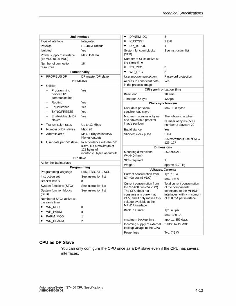
Technical Specifications
4-13Automation System S7-400 CPU SpecificationsA5E00165965-01
2nd InterfaceType of interface Integrated
Physical RS 485/Profibus
Isolated Yes
Power supply to interface(15 VDC to 30 VDC)
Max. 150 mA
Number of connectionresources
16
Functionality
• PROFIBUS DP DP master/DP slave
DP Master
• Utilities
– Programmingdevice/OPcommunication
Yes
– Routing Yes
– Equidistance Yes
– SYNC/FREEZE Yes
– Enable/disable DPslaves
Yes
• Transmission rates Up to 12 Mbps
• Number of DP slaves Max. 96
• Address area Max. 6 Kbytes inputs/6Kbytes outputs
• User data per DP slave In accordance with the DPslave, but a maximum of128 bytes ofinputs/128 bytes of outputs
DP slave
As for the 1st interface
ProgrammingProgramming language LAD, FBD, STL, SCL
Instruction set See instruction list
Bracket levels 8
System functions (SFC) See instruction list
System function blocks(SFB)
See instruction list
Number of SFCs active atthe same time
• WR_REC 8
• WR_PARM 8
• PARM_MOD 1
• WR_DPARM 2
• DPNRM_DG 8
• RDSYSST 1 to 8
• DP_TOPOL 1
System function blocks(SFB)
See instruction list
Number of SFBs active atthe same time
• RD_REC 8
• WR_REC 8
User program protection Password protection
Access to consistent datain the process image
Yes
CiR synchronization time
Base load 100 ms
Time per I/O byte 120 µs
Clock synchronism
User data per clocksynchronous slave
Max. 128 bytes
Maximum number of bytesand slaves in a processimage partition
The following applies:
Number of bytes / 50 +number of slaves < 20
Equidistance Yes
Shortest clock pulse 5 ms
2.5 ms without use of SFC126, 127
Dimensions
Mounting dimensionsW×H×D (mm)
25×290×219
Slots required 1
Weight approx. 0.72 kg
Voltages, CurrentsCurrent consumption fromS7-400 bus (5 VDC)
Typ. 1.5 A
Max. 1.6 A
Current consumption fromthe S7-400 bus (24 VDC)The CPU does notconsume any current at24 V, and it only makes thisvoltage available at theMPI/DP interface.
Total current consumptionof the componentsconnected to the MPI/DPinterfaces, with a maximumof 150 mA per interface
Backup current Typ. 40 �A
Max. 380 �A
maximum backup time approx. 356 days
Incoming supply of externalbackup voltage to the CPU
5 VDC to 15 VDC
Power loss Typ. 7.5 W
CPU as DP SlaveYou can only configure the CPU once as a DP slave even if the CPU has severalinterfaces.

Technical Specifications
4-14Automation System S7-400 CPU Specifications
A5E00165965-01
4.4 Technical Specifications of the CPU 414-3; (6ES7414-3XJ00-0AB0)
CPU and VersionMLFB 6ES7414-3XJ00-0AB0
• Firmware version V 3.1
Associated programmingpackage
As of STEP7 V 5.2
Memory
Working memory
• Integrated 384 Kbytes for code
384 Kbytes for data
• Expandable No
Load memory
• Integrated 256 Kbytes RAM
• Expandable FEPROM With memory card (FLASH)up to 64 Mbytes
• Expandable RAM With memory card (RAM)up to 64 Mbytes
Backup Yes
• With battery All data
• Without battery None
Processing Times
Processing times for
• Bit operations Min. 0.1 �s
• Word instructions Min. 0.1 �s
• Integer mathinstructions
Min. 0.1 �s
• Floating-point mathinstructions
Min. 0.6 �s
Timers/Counters and Their RetentivityS7 counters 256
• Retentivity can be set From Z 0 to Z 255
• Preset From Z 0 to Z 7
• Counting range 1 to 999
IEC counter Yes
• Type SFB
S7 timers 256
• Retentivity can be set From T 0 to T 255
• Preset No retentive timers
• Time range 10 ms to 9990 s
IEC timers Yes
• Type SFB
Data Areas and Their RetentivityTotal retentive data areas(including memory bits;times; counts)
Total working and loadmemory (with backupbattery)
Memory markers 8 Kbytes
• Retentivity can be set From MB 0 to MB 8191
• Preset retentivity From MB 0 to MB 15
Clock memories 8 (1 memory byte)
Data blocks Max. 4095 (DB 0 reserved)
• Size Max. 64 Kbytes
Local data (can be set) Max. 16 Kbytes
• Preset 8 Kbytes
Blocks
OBs See instruction list
• Size Max. 64 Kbytes
Nesting depth
• Per priority class 24
• Additionally in an errorOB
2
FBs Max. 2048
• Size Max. 64 Kbytes
FCs Max. 2048
• Size Max. 64 Kbytes
Address Areas (Inputs/Outputs)
Total I/O address area 8 Kbytes/8 Kbytes
• Of which distributed
MPI/DP interface 2 Kbytes/2 Kbytes
DP interface 6 Kbytes/6 Kbytes
The distributed I/O address area is halved for each strandoperated clock synchronously, i.e. in which an OB 61 toOB 63 is assigned.
Process Image 8 Kbytes/8 Kbytes (can be set)
• Preset 256 bytes/256 bytes
• Number of partialprocess images
Max. 8
• Consistent data Max. 244 bytes
Digital channels 65536/65536
• Of which central 65536/65536
Analog channels 4096/4096
• Of which central 4096/4096

Technical Specifications
4-15Automation System S7-400 CPU SpecificationsA5E00165965-01
ConfigurationCentral racks/expansionunits
Max. 1/21
Multicomputing Max. 4 CPUs (with UR1 or UR2)
Number of plug-in IMs(overall)
Max. 6
• IM 460 Max. 6
• IM 463-2 Max. 4
Number of DP masters
• Integrated 2
• Via IF 964-DP 1
• Via IM 467 Max. 4
• Via CP Max. 10
IM 467 cannot be used with the CP 443-5 Extended
Number of plug-in S5modules via adapter casing(in the central rack)
Max. 6
Operable function modulesand communicationprocessors
• FM Limited by the number ofslots and the number ofconnections
• CP 440 Limited by the number ofslots
• CP 441 Limited by the number ofconnections
• Profibus and EthernetCPs incl. CP 443-5Extended and IM 467
Max. 14
Time
Clock Yes
• Buffered Yes
• Resolution 1 ms
• Accuracy at
– Power off Deviation per day 1.7 s
– Power on Deviation per day 8.6 s
Runtime meter 8
• Number 0 to 7
• Value Range 0 to 32767 hours
• Granularity 1 hour
• Retentive Yes
Time synchronization Yes
• In PLC, on MPI, DPand IF 964 DP
as master or slave
Time of day difference inthe system forsynchronization via
• ETHERNET maximum 10 ms
• MPI maximum 200 ms
S7 Message FunctionsNumber of stations that canlog on for messagefunctions (e.g. WIN CC orSIMATIC OP)
Max. 8
Symbol-related messages Yes
• Number of messages
– Overall
– 100 ms grid
– 500 ms grid
– 1000 ms grid
Max. 512
Max. 128
Max. 256
Max. 512
• Number of additionalvalues per message
– With 100 ms grid Max. 1
– With 500, 1000 msgrid
Max. 10
Block-related messages Yes
• Simultaneously activeALARM-S/SQ blocksand ALARM-D/DQblocks
Max. 100
ALARM-8 blocks Yes
• Number ofcommunication jobs forALARM-8 blocks andblocks for S7communication (can beset)
Max. 600
• Preset 300
Process control reports Yes
Number of archives thatcan log on simultaneously(SFB 37 AR_SEND)
16
Test and Startup Functions
Monitor/modify variable Yes
• Variables Inputs/outputs, memorymarkers, DB, distributedinputs/outputs, timers,counters
• Number of variables Max. 70
Force Yes
• Variables Inputs/outputs, memorymarkers, distributedinputs/outputs
• Number of variables Max. 256
Status block Yes
Single sequence Yes
Diagnostic buffer Yes
• Number of entries Max. 3200 (can be set)
• Preset 120
Number of breakpoints 4

Technical Specifications
4-16Automation System S7-400 CPU Specifications
A5E00165965-01
Communication FunctionsProgramming device/OPcommunication
Yes
Number of connectableOPs
31 without messageprocessing, 8 with messageprocessing
Number of connectionresources for S7connections via allinterfaces and CPs
32, with one each of thosereserved for PG and OP
Global data communication Yes
• Number of GD circuits Max. 8
• Number of GDpackages
– Sender Max. 8
– Receiver Max. 16
• Size of GD packages Max. 64 bytes
– Of which consistent 1 variable
S7 basic communication Yes
• User data per job Max. 76 bytes
– Of which consistent 16 Byte
S7 communication Yes
• User data per job Max. 64 Kbytes
– Of which consistent 1 variable (462 bytes)
S5-compatiblecommunication
Yes (via CP – max. 10 –and FC AG_SEND and FCAG_RECV)
• User data per job Max. 8 Kbytes
– Of which consistent 240 bytes
Standard communication(FMS)
Yes (via CP and loadableFB)
Interfaces1st Interface
Type of interface Integrated
Physical RS 485/Profibus
Isolated Yes
Power supply to interface(15 VDC to 30 VDC)
Max. 150 mA
Number of connectionresources
MPI: 32DP: 16
Functionality
• MPI Yes
• PROFIBUS DP DP master/DP slave
MPI
• Utilities
– Programmingdevice/OPcommunication
Yes
– Routing Yes
– Global datacommunication
Yes
– S7 basiccommunication
Yes
– S7 communication Yes
• Transmission rates Up to 12 Mbps
DP Master• Utilities
– Programmingdevice/OPcommunication
Yes
– Routing Yes
– Equidistance Yes
– SYNC/FREEZE Yes
– Enable/disable DPslaves
Yes
• Transmission rates Up to 12 Mbps
• Number of DP slaves Max. 32
• Address area Max. 2 Kbytes inputs/2Kbytes outputs
• User data per DP slave Maximum 244 bytes E,maximum 244 bytes A,distributed over 244 slotseach with 128 bytes
DP slave• Utilities
– Monitor/modify
– Programming
– Routing
Yes, if the interface is active
Yes, if the interface is active
Yes, if the interface is active
• DDB (GSD) file http://www.ad.siemens.de/csi_e/gsd
• Transmission rate Up to 12 Mbps
• Intermediate memory 244 bytes inputs/ 244 bytesoutputs
– Address areas
– User data peraddress area
– Of which consistent
Max. 32
Max. 32 bytes
32 bytes
2nd Interface
Type of interface Integrated
Physical RS 485/Profibus
Isolated Yes
Power supply to interface(15 VDC to 30 VDC)
Max. 150 mA
Number of connectionresources
16

Technical Specifications
4-17Automation System S7-400 CPU SpecificationsA5E00165965-01
Functionality• PROFIBUS DP DP master/DP slave
DP Master
• Utilities
– Programmingdevice/OPcommunication
Yes
– Routing Yes
– Equidistance Yes
– SYNC/FREEZE Yes
– Enable/disable DPslaves
Yes
• Transmission rates Up to 12 Mbps
• Number of DP slaves Max. 96
• Address area Max. 6 Kbytes inputs/6Kbytes outputs
• User data per DP slave In accordance with the DPslave, but a maximum of128 bytes ofinputs/128 bytes of outputs
DP slave
As for the 1st interface
3rd Interface
Type of interface Plug-in interface submodule
Insertable interfacesubmodule
IF-964-DP
Technical features as for the 2nd interface
Programming
Programming language LAD, FBD, STL, SCL
Instruction set See instruction list
Bracket levels 8
System functions (SFC) See instruction list
Number of SFCs active atthe same time
• WR_REC 8
• WR_PARM 8
• PARM_MOD 1
• WR_DPARM 2
• DPNRM_DG 8
• RDSYSST 1 to 8
• DP_TOPOL 1
System function blocks(SFB)
See instruction list
Number of SFBs active atthe same time
• RD_REC 8
• WR_REC 8
User program protection Password protection
Access to consistent datain the process image
Yes
CiR synchronization time
Base load 100 ms
Time per I/O byte 120 µs
Clock synchronism
User data per clocksynchronous slave
Max. 128 bytes
Maximum number of bytesand slaves in a processimage partition
The following applies:
Number of bytes / 50 +number of slaves < 20
Equidistance Yes
Shortest clock pulse 5 ms
2.5 ms without use of SFC126, 127
Dimensions
Mounting dimensionsW×H×D (mm)
50×290×219
Slots required 2
Weight approx. 1.07 kg
Voltages, Currents
Current consumption fromS7-400 bus (5 VDC)
Typ. 1.5 AMax. 1.6 A
Current consumption fromthe S7-400 bus (24 VDC)The CPU does notconsume any current at24 V, and it only makes thisvoltage available at theMPI/DP interface.
Total current consumptionof the componentsconnected to the MPI/DPinterfaces, with a maximumof 150 mA per interface
Backup current Typ 40 �AMax. 420 �A
maximum backup time approx 356 days
Incoming supply of externalbackup voltage to the CPU
5 VDC to 15 VDC
Power loss Typ. 7.5 W
CPU as DP Slave
You can only configure the CPU once as a DP slave even if the CPU has severalinterfaces.

Technical Specifications
4-18Automation System S7-400 CPU Specifications
A5E00165965-01
4.5 Technical Specifications of the CPU 416-2; (6ES7416-2XK02-0AB0, 6ES7416-2FK02-0AB0)
CPU and VersionMLFB 6ES7416-2XK02-0AB0
• Firmware version V 3.1
Associated programmingpackage
As of STEP7 V 5.2
Memory
Working memory
• Integrated 0.8 Mbytes for code
0.8 Mbytes for data
• Expandable No
Load memory
• Integrated 256 Kbytes RAM
• Expandable FEPROM With memory card (FLASH)up to 64 Mbytes
• Expandable RAM With memory card (RAM)up to 64 Mbytes
Backup Yes
• With battery All data
• Without battery None
Processing Times
Processing times for
• Bit operations Min. 0.08 �s
• Word instructions Min. 0.08 �s
• Integer mathinstructions
Min. 0.08 �s
• Floating-point mathinstructions
Min. 0.48 �s
Timers/Counters and Their RetentivityS7 counters 512
• Retentivity can be set From Z 0 to Z 511
• Preset From Z 0 to Z 7
• Counting range 1 to 999
IEC counter Yes
• Type SFB
S7 timers 512
• Retentivity can be set From T 0 to T 511
• Preset No retentive timers
• Time range 10 ms to 9990 s
IEC timers Yes
• Type SFB
Data Areas and Their RetentivityTotal retentive data areas(including memory bits;times; counts)
Total working and loadmemory (with backupbattery)
Memory markers 16 Kbytes
• Retentivity can be set From MB 0 to MB 16383
• Preset retentivity From MB 0 to MB 15
Clock memories 8 (1 memory byte)
Data blocks Max. 4095 (DB 0 reserved)
• Size Max. 64 Kbytes
Local data (can be set) Max. 32 Kbytes
• Preset 16 Kbytes
Blocks
OBs See instruction list
• Size Max. 64 Kbytes
Nesting depth
• Per priority class 24
• Additionally in an errorOB
2
FBs Max. 2048
• Size Max. 64 Kbytes
FCs Max. 2048
• Size Max. 64 Kbytes
Address Areas (Inputs/Outputs)
Total I/O address area 16 Kbytes/16 Kbytes
• Of which distributed
MPI/DP interface 2 Kbytes/2 Kbytes
DP interface 8 Kbytes/8 Kbytes
The distributed I/O address area is halved for each strandoperated clock synchronously, i.e. in which an OB 61/62is assigned.
Process Image 16 Kbytes/16 Kbytes (can be set)
• Preset 512 bytes/512 bytes
• Number of partialprocess images
Max. 8
• Consistent data Max. 244 bytes
Digital channels 131072/131072
• Of which central 131072/131072
Analog channels 8192/8192
• Of which central 8192/8192

Technical Specifications
4-19Automation System S7-400 CPU SpecificationsA5E00165965-01
ConfigurationCentral racks/expansionunits
Max. 1/21
Multicomputing Max. 4 CPUs (with UR1 or UR2)
Number of plug-in IMs(overall)
Max. 6
• IM 460 Max. 6
• IM 463-2 Max. 4
Number of DP masters
• Integrated 2
• Via IM 467 Max. 4
• Via CP Max. 10
IM 467 cannot be used with the CP 443-5 Extended
Number of plug-in S5modules via adapter casing(in the central rack)
Max. 6
Operable function modulesand communicationprocessors
• FM Limited by the number ofslots and the number ofconnections
• CP 440 Limited by the number ofslots
• CP 441 Limited by the number ofconnections
• Profibus and EthernetCPs incl. CP 443-5Extended and IM 467
Max. 14
Time
Clock Yes
• Buffered Yes
• Resolution 1 ms
• Accuracy at
– Power off Deviation per day 1.7 s
– Power on Deviation per day 8.6 s
Runtime meter 8
• Number 0 to 7
• Value Range 0 to 32767 hours
• Granularity 1 hour
• Retentive Yes
Time synchronization Yes
• In PLC, on MPI and DP as master or slave
Time of day difference inthe system forsynchronization via
• ETHERNET maximum 10 ms
• MPI maximum 200 ms
S7 Message FunctionsNumber of stations that canlog on for messagefunctions (e.g. WIN CC orSIMATIC OP)
Max. 12
Symbol-related messages Yes
• Number of messages
– Overall
– 100 ms grid
– 500 ms grid
– 1000 ms grid
Max. 1024
Max. 128
Max. 512
Max. 1024
• Number of additionalvalues per message
– With 100 ms grid Max. 1
– With 500, 1000 msgrid
Max. 10
Block-related messages Yes
• Simultaneously activeALARM-S/SQ blocksand ALARM-D/DQblocks
Max. 200
ALARM-8 blocks Yes
• Number ofcommunication jobs forALARM-8 blocks andblocks for S7communication (can beset)
Max. 1800
• Preset 600
Process control reports Yes
Number of archives thatcan log on simultaneously(SFB 37 AR_SEND)
32
Test and Startup Functions
Monitor/modify variable Yes
• Variables Inputs/outputs, memorymarkers, DB, distributedinputs/outputs, timers,counters
• Number of variables Max. 70
Force Yes
• Variables Inputs/outputs, memorymarkers, distributedinputs/outputs
• Number of variables Max. 512
Status block Yes
Single sequence Yes
Diagnostic buffer Yes
• Number of entries Max. 3200 (can be set)
• Preset 120
Number of breakpoints 4
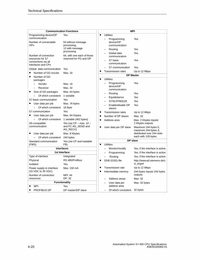
Technical Specifications
4-20Automation System S7-400 CPU Specifications
A5E00165965-01
Communication FunctionsProgramming device/OPcommunication
Yes
Number of connectableOPs
63 without messageprocessing, 12 with messageprocessing
Number of connectionresources for S7connections via allinterfaces and CPs
64, with one each of thosereserved for PG and OP
Global data communication Yes
• Number of GD circuits Max. 16
• Number of GDpackages
– Sender Max. 16
– Receiver Max. 32
• Size of GD packages Max. 64 bytes
– Of which consistent 1 variable
S7 basic communication Yes
• User data per job Max. 76 bytes
– Of which consistent 16 Byte
S7 communication Yes
• User data per job Max. 64 Kbytes
– Of which consistent 1 variable (462 bytes)
S5-compatiblecommunication
Yes (via CP – max. 10 –and FC AG_SEND andAG_RECV)
• User data per job Max. 8 Kbytes
– Of which consistent 240 bytes
Standard communication(FMS)
Yes (via CP and loadableFB)
Interfaces1st Interface
Type of interface Integrated
Physical RS 485/Profibus
Isolated Yes
Power supply to interface(15 VDC to 30 VDC)
Max. 150 mA
Number of connectionresources
MPI: 44DP: 32
Functionality
• MPI Yes
• PROFIBUS DP DP master/DP slave
MPI• Utilities
– Programmingdevice/OPcommunication
Yes
– Routing Yes
– Global datacommunication
Yes
– S7 basiccommunication
Yes
– S7 communication Yes
• Transmission rates Up to 12 Mbps
DP Master
• Utilities
– Programmingdevice/OPcommunication
Yes
– Routing Yes
– Equidistance Yes
– SYNC/FREEZE Yes
– Enable/disable DPslaves
Yes
• Transmission rates Up to 12 Mbps
• Number of DP slaves Max. 32
• Address area Max. 2 Kbytes inputs/ 2 Kbytes outputs
• User data per DP slave Maximum 244 bytes E,maximum 244 bytes A,distributed over 244 slotseach with 128 bytes
DP slave
• Utilities
– Monitor/modify
– Programming
– Routing
Yes, if the interface is active
Yes, if the interface is active
Yes, if the interface is active
• DDB (GSD) file http://www.ad.siemens.de/csi_e/gsd
• Transmission rate Up to 12 Mbps
• Intermediate memory 244 bytes inputs/ 244 bytesoutputs
– Address areas
– User data peraddress area
– Of which consistent
Max. 32
Max. 32 bytes
32 bytes
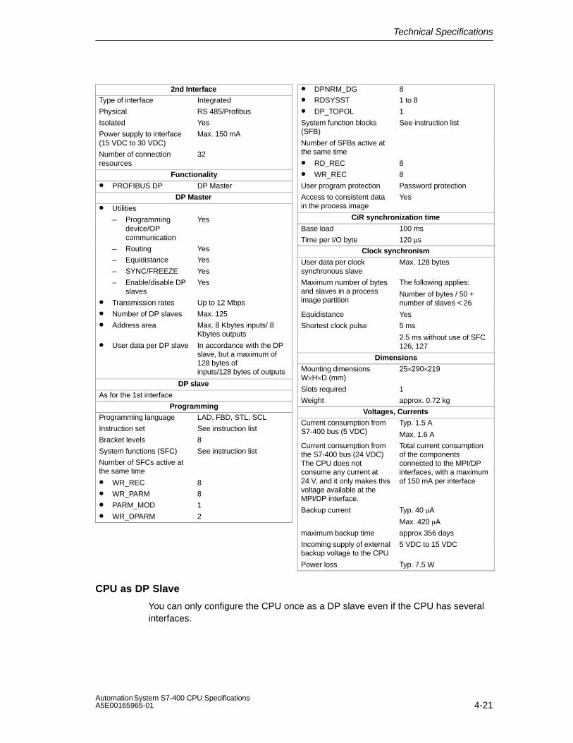
Technical Specifications
4-21Automation System S7-400 CPU SpecificationsA5E00165965-01
2nd InterfaceType of interface Integrated
Physical RS 485/Profibus
Isolated Yes
Power supply to interface(15 VDC to 30 VDC)
Max. 150 mA
Number of connectionresources
32
Functionality
• PROFIBUS DP DP Master
DP Master
• Utilities
– Programmingdevice/OPcommunication
Yes
– Routing Yes
– Equidistance Yes
– SYNC/FREEZE Yes
– Enable/disable DPslaves
Yes
• Transmission rates Up to 12 Mbps
• Number of DP slaves Max. 125
• Address area Max. 8 Kbytes inputs/ 8Kbytes outputs
• User data per DP slave In accordance with the DPslave, but a maximum of128 bytes ofinputs/128 bytes of outputs
DP slave
As for the 1st interface
ProgrammingProgramming language LAD, FBD, STL, SCL
Instruction set See instruction list
Bracket levels 8
System functions (SFC) See instruction list
Number of SFCs active atthe same time
• WR_REC 8
• WR_PARM 8
• PARM_MOD 1
• WR_DPARM 2
• DPNRM_DG 8
• RDSYSST 1 to 8
• DP_TOPOL 1
System function blocks(SFB)
See instruction list
Number of SFBs active atthe same time
• RD_REC 8
• WR_REC 8
User program protection Password protection
Access to consistent datain the process image
Yes
CiR synchronization time
Base load 100 ms
Time per I/O byte 120 µs
Clock synchronism
User data per clocksynchronous slave
Max. 128 bytes
Maximum number of bytesand slaves in a processimage partition
The following applies:
Number of bytes / 50 +number of slaves < 26
Equidistance Yes
Shortest clock pulse 5 ms
2.5 ms without use of SFC126, 127
Dimensions
Mounting dimensionsW×H×D (mm)
25×290×219
Slots required 1
Weight approx. 0.72 kg
Voltages, CurrentsCurrent consumption fromS7-400 bus (5 VDC)
Typ. 1.5 A
Max. 1.6 A
Current consumption fromthe S7-400 bus (24 VDC)The CPU does notconsume any current at24 V, and it only makes thisvoltage available at theMPI/DP interface.
Total current consumptionof the componentsconnected to the MPI/DPinterfaces, with a maximumof 150 mA per interface
Backup current Typ. 40 �A
Max. 420 �A
maximum backup time approx 356 days
Incoming supply of externalbackup voltage to the CPU
5 VDC to 15 VDC
Power loss Typ. 7.5 W
CPU as DP Slave
You can only configure the CPU once as a DP slave even if the CPU has severalinterfaces.
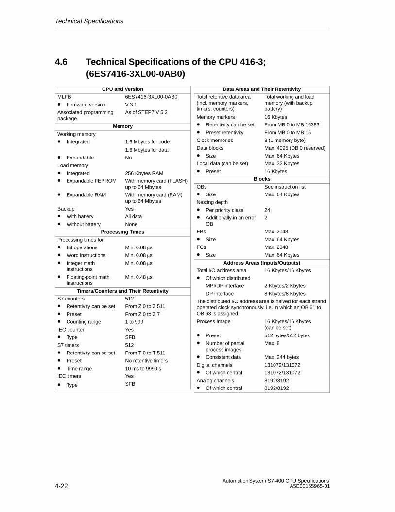
Technical Specifications
4-22Automation System S7-400 CPU Specifications
A5E00165965-01
4.6 Technical Specifications of the CPU 416-3; (6ES7416-3XL00-0AB0)
CPU and VersionMLFB 6ES7416-3XL00-0AB0
• Firmware version V 3.1
Associated programmingpackage
As of STEP7 V 5.2
Memory
Working memory
• Integrated 1.6 Mbytes for code
1.6 Mbytes for data
• Expandable No
Load memory
• Integrated 256 Kbytes RAM
• Expandable FEPROM With memory card (FLASH)up to 64 Mbytes
• Expandable RAM With memory card (RAM)up to 64 Mbytes
Backup Yes
• With battery All data
• Without battery None
Processing Times
Processing times for
• Bit operations Min. 0.08 �s
• Word instructions Min. 0.08 �s
• Integer mathinstructions
Min. 0.08 �s
• Floating-point mathinstructions
Min. 0.48 �s
Timers/Counters and Their RetentivityS7 counters 512
• Retentivity can be set From Z 0 to Z 511
• Preset From Z 0 to Z 7
• Counting range 1 to 999
IEC counter Yes
• Type SFB
S7 timers 512
• Retentivity can be set From T 0 to T 511
• Preset No retentive timers
• Time range 10 ms to 9990 s
IEC timers Yes
• Type SFB
Data Areas and Their RetentivityTotal retentive data area(incl. memory markers,timers, counters)
Total working and loadmemory (with backupbattery)
Memory markers 16 Kbytes
• Retentivity can be set From MB 0 to MB 16383
• Preset retentivity From MB 0 to MB 15
Clock memories 8 (1 memory byte)
Data blocks Max. 4095 (DB 0 reserved)
• Size Max. 64 Kbytes
Local data (can be set) Max. 32 Kbytes
• Preset 16 Kbytes
Blocks
OBs See instruction list
• Size Max. 64 Kbytes
Nesting depth
• Per priority class 24
• Additionally in an errorOB
2
FBs Max. 2048
• Size Max. 64 Kbytes
FCs Max. 2048
• Size Max. 64 Kbytes
Address Areas (Inputs/Outputs)
Total I/O address area 16 Kbytes/16 Kbytes
• Of which distributed
MPI/DP interface 2 Kbytes/2 Kbytes
DP interface 8 Kbytes/8 Kbytes
The distributed I/O address area is halved for each strandoperated clock synchronously, i.e. in which an OB 61 toOB 63 is assigned.
Process Image 16 Kbytes/16 Kbytes (can be set)
• Preset 512 bytes/512 bytes
• Number of partialprocess images
Max. 8
• Consistent data Max. 244 bytes
Digital channels 131072/131072
• Of which central 131072/131072
Analog channels 8192/8192
• Of which central 8192/8192

Technical Specifications
4-23Automation System S7-400 CPU SpecificationsA5E00165965-01
ConfigurationCentral racks/expansionunits
Max. 1/21
Multicomputing Max. 4 CPUs (with UR1 or UR2)
Number of plug-in IMs(overall)
Max. 6
• IM 460 Max. 6
• IM 463-2 Max. 4
Number of DP masters
• Integrated 2
• Via IF 964-DP 1
• Via IM 467 Max. 4
• Via CP Max. 10
IM 467 cannot be used with the CP 443-5 Extended
Number of plug-in S5modules via adapter casing(in the central rack)
Max. 6
Operable function modulesand communicationprocessors
• FM Limited by the number ofslots and the number ofconnections
• CP 440 Limited by the number ofslots
• CP 441 Limited by the number ofconnections
• Profibus and EthernetCPs incl. CP 443-5Extended and IM 467
Max. 14
Time
Clock Yes
• Buffered Yes
• Resolution 1 ms
• Accuracy at
– Power off Deviation per day 1.7 s
– Power on Deviation per day 8.6 s
Runtime meter 8
• Number 0 to 7
• Value Range 0 to 32767 hours
• Granularity 1 hour
• Retentive Yes
Time synchronization Yes
• In PLC, on MPI, DPand IF 964 DP
as master or slave
Time of day difference inthe system forsynchronization via
• ETHERNET maximum 10 ms
• MPI maximum 200 ms
S7 Message FunctionsNumber of stations that canlog on for messagefunctions (e.g. WIN CC orSIMATIC OP)
Max. 12
Symbol-related messages Yes
• Number of messages
– Overall
– 100 ms grid
– 500 ms grid
– 1000 ms grid
Max. 1024
Max. 128
Max. 512
Max. 1024
• Number of additionalvalues per message
– With 100 ms grid Max. 1
– With 500, 1000 msgrid
Max. 10
Block-related messages Yes
• Simultaneously activeALARM-S/SQ blocksand ALARM-D/DQblocks
Max. 200
ALARM-8 blocks Yes
• Number ofcommunication jobs forALARM-8 blocks andblocks for S7communication (can beset)
Max. 1800
• Preset 600
Process control reports Yes
Number of archives thatcan log on simultaneously(SFB 37 AR_SEND)
32
Test and Startup Functions
Monitor/modify variable Yes
• Variables Inputs/outputs, memorymarkers, DB, distributedinputs/outputs, timers,counters
• Number of variables Max. 70
Force Yes
• Variables Inputs/outputs, memorymarkers, distributedinputs/outputs
• Number of variables Max. 512
Status block Yes
Single sequence Yes
Diagnostic buffer Yes
• Number of entries Max. 3200 (can be set)
• Preset 120
Number of breakpoints 4

Technical Specifications
4-24Automation System S7-400 CPU Specifications
A5E00165965-01
Communication FunctionsProgramming device/OPcommunication
Yes
Number of connectableOPs
63 without messageprocessing, 12 with messageprocessing
Number of connectionresources for S7connections via allinterfaces and CPs
64, with one each of thosereserved for PG and OP
Global data communication Yes
• Number of GD circuits Max. 16
• Number of GDpackages
– Sender Max. 16
– Receiver Max. 32
• Size of GD packages Max. 64 bytes
– Of which consistent 1 variable
S7 basic communication Yes
• User data per job Max. 76 bytes
– Of which consistent 16 Byte
S7 communication Yes
• User data per job Max. 64 Kbytes
– Of which consistent 1 variable (462 bytes)
S5-compatiblecommunication
Yes (via CP – max. 10 –and FC AG_SEND andAG_RECV)
• User data per job Max. 8 Kbytes
– Of which consistent 240 bytes
Standard communication(FMS)
Yes (via CP and loadableFB)
Interfaces1st Interface
Type of interface Integrated
Physical RS 485/Profibus
Isolated Yes
Power supply to interface(15 VDC to 30 VDC)
Max. 150 mA
Number of connectionresources
MPI: 44DP: 32
Functionality
• MPI Yes
• PROFIBUS DP DP master/DP slave
MPI
• Utilities
– Programmingdevice/OPcommunication
Yes
– Routing Yes
– Global datacommunication
Yes
– S7 basiccommunication
Yes
– S7 communication Yes
• Transmission rates Up to 12 Mbps
DP Master• Utilities
– Programmingdevice/OPcommunication
Yes
– Routing Yes
– Equidistance Yes
– SYNC/FREEZE Yes
– Enable/disable DPslaves
Yes
• Transmission rates Up to 12 Mbps
– Of which reserved 1 for programming device,1 for OP
• Number of DP slaves Max. 32
• Address area Max. 2 Kbytes inputs/2Kbytes outputs
• User data per DP slave Maximum 244 bytes E,maximum 244 bytes A,distributed over 244 slotseach with 128 bytes
DP slave
• Utilities
– Monitor/modify
– Programming
– Routing
Yes, if the interface is active
Yes, if the interface is active
Yes, if the interface is active
• DDB (GSD) file http://www.ad.siemens.de/csi_e/gsd
• Transmission rate Up to 12 Mbps
• Intermediate memory 244 bytes inputs/ 244 bytesinputs
– Address areas
– User data peraddress area
– Of which consistent
Max. 32
Max. 32 bytes
32 bytes
2nd Interface
Type of interface Integrated
Physical RS 485/Profibus
Isolated Yes
Power supply to interface(15 VDC to 30 VDC)
Max. 150 mA
Number of connectionresources
32
Functionality
• PROFIBUS DP DP master/DP slave
DP Master
• Utilities
– Programmingdevice/OPcommunication
Yes
– Routing Yes
– Equidistance Yes
– SYNC/FREEZE Yes
– Enable/disable DPslaves
Yes
• Transmission rates Up to 12 Mbps

Technical Specifications
4-25Automation System S7-400 CPU SpecificationsA5E00165965-01
• Number of DP slaves Max. 125
• Address area Max. 8 Kbytes inputs/ 8Kbytes outputs
• User data per DP slave In accordance with the DPslave, but a maximum of128 bytes ofinputs/128 bytes of outputs
DP slave
As for the 1st interface
3rd Interface
Type of interface Plug-in interface submodule
Insertable interfacesubmodule
IF-964-DP
Technical features as for the 2nd interface
Programming
Programming language LAD, FBD, STL, SCL
Instruction set See instruction list
Bracket levels 8
System functions (SFC) See instruction list
Number of SFCs active atthe same time
• WR_REC 8
• WR_PARM 8
• PARM_MOD 1
• WR_DPARM 2
• DPNRM_DG 8
• RDSYSST 1 to 8
• DP_TOPOL 1
System function blocks(SFB)
See instruction list
Number of SFBs active atthe same time
• RD_REC 8
• WR_REC 8
User program protection Password protection
Access to consistent datain the process image
Yes
CiR synchronization time
Base load 100 ms
Time per I/O byte 120 µs
Clock synchronism
User data per clocksynchronous slave
Max. 128 bytes
Maximum number of bytesand slaves in a processimage partition
The following applies:
Number of bytes / 50 +number of slaves < 26
Equidistance Yes
Shortest clock pulse 5 ms
2.5 ms without use of SFC126, 127
Dimensions
Mounting dimensionsW×H×D (mm)
50×290×219
Slots required 2
Weight approx. 1.07 kg
Voltages, Currents
Current consumption fromS7-400 bus (5 VDC)
Typ. 1.6 A
Max. 1.8 A
Current consumption fromthe S7-400 bus (24 VDC)The CPU does notconsume any current at 24V, and it only makes thisvoltage available at theMPI/DP interface.
Total current consumptionof the componentsconnected to the MPI/DPinterfaces, with a maximumof 150 mA per interface
Backup current Typ. 50 �A
Max. 460 �A
maximum backup time approx 332 days
Incoming supply of externalbackup voltage to the CPU
5 VDC to 15 VDC
Power loss Typ. 8 W
CPU as DP Slave
You can only configure the CPU once as a DP slave even if the CPU has severalinterfaces.

Technical Specifications
4-26Automation System S7-400 CPU Specifications
A5E00165965-01
4.7 Technical Specifications of the CPU 417-4; (6ES7417-4XL00-0AB0)
CPU and VersionMLFB 6ES7417-4XL00-0AB0
• Firmware version V 3.1
Associated programmingpackage
As of STEP7 V 5.2
Memory
Working memory
• Integrated 2 Mbytes for code
2 Mbytes for data
• Expandable Up to 10 Mbytes for code
Up to 10 Mbytes for data
Load memory
• Integrated 256 Kbytes RAM
• Expandable FEPROM With memory card (FLASH)up to 64 Mbytes
• Expandable RAM With memory card (RAM)up to 64 Mbytes
Backup Yes
• With battery All data
• Without battery None
Processing Times
Processing times for
• Bit operations Min. 0.1 �s
• Word instructions Min. 0.1 �s
• Integer mathinstructions
Min. 0.1 �s
• Floating-point mathinstructions
Min. 0.6 �s
Timers/Counters and Their RetentivityS7 counters 512
• Retentivity can be set From Z 0 to Z 511
• Preset From Z 0 to Z 7
• Counting range 1 to 999
IEC counter Yes
• Type SFB
S7 timers 512
• Retentivity can be set From T 0 to T 511
• Preset No retentive timers
• Time range 10 ms to 9990 s
IEC timers Yes
• Type SFB
Data Areas and Their Retentivity
Total retentive data areas(including memory bits;times; counts)
Total working and loadmemory (with backupbattery)
Memory markers 16 Kbytes
• Retentivity can be set From MB 0 to MB 16383
• Preset retentivity From MB 0 to MB 15
Clock memories 8 (1 memory byte)
Data blocks Max. 8191 (DB 0 reserved)
• Size Max. 64 Kbytes
Local data (can be set) Max. 64 Kbytes
• Preset 32 Kbytes
Blocks
OBs See instruction list
• Size Max. 64 Kbytes
Nesting depth
• Per priority class 24
• Additionally in an errorOB
2
FBs Max. 6144
• Size Max. 64 Kbytes
FCs Max. 6144
• Size Max. 64 Kbytes
Address Areas (Inputs/Outputs)
Total I/O address area 16 Kbytes/16 Kbytes
• Of which distributed
MPI/DP interface 2 Kbytes/2 Kbytes
DP interface 8 Kbytes/8 Kbytes
The distributed I/O address area is halved for each strandoperated clock synchronously, i.e. in which an OB 61 toOB 64 is assigned.
Process Image 16 Kbytes/16 Kbytes (can be set)
• Preset 1024 bytes/1024 bytes
• Number of partialprocess images
Max. 15
• Consistent data Max. 244 bytes
Digital channels 131072/131072
• Of which central 131072/131072
Analog channels 8192/8192
• Of which central 8192/8192
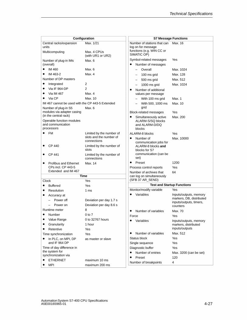
Technical Specifications
4-27Automation System S7-400 CPU SpecificationsA5E00165965-01
ConfigurationCentral racks/expansionunits
Max. 1/21
Multicomputing Max. 4 CPUs (with UR1 or UR2)
Number of plug-in IMs(overall)
Max. 6
• IM 460 Max. 6
• IM 463-2 Max. 4
Number of DP masters
• Integrated 2
• Via IF 964-DP 2
• Via IM 467 Max. 4
• Via CP Max. 10
IM 467 cannot be used with the CP 443-5 Extended
Number of plug-in S5modules via adapter casing(in the central rack)
Max. 6
Operable function modulesand communicationprocessors
• FM Limited by the number ofslots and the number ofconnections
• CP 440 Limited by the number ofslots
• CP 441 Limited by the number ofconnections
• Profibus and EthernetCPs incl. CP 443-5Extended and IM 467
Max. 14
Time
Clock Yes
• Buffered Yes
• Resolution 1 ms
• Accuracy at
– Power off Deviation per day 1.7 s
– Power on Deviation per day 8.6 s
Runtime meter 8
• Number 0 to 7
• Value Range 0 to 32767 hours
• Granularity 1 hour
• Retentive Yes
Time synchronization Yes
• In PLC, on MPI, DPand IF 964 DP
as master or slave
Time of day difference inthe system forsynchronization via
• ETHERNET maximum 10 ms
• MPI maximum 200 ms
S7 Message FunctionsNumber of stations that canlog on for messagefunctions (e.g. WIN CC orSIMATIC OP)
Max. 16
Symbol-related messages Yes
• Number of messages
– Overall
– 100 ms grid
– 500 ms grid
– 1000 ms grid
Max. 1024
Max. 128
Max. 512
Max. 1024
• Number of additionalvalues per message
– With 100 ms grid Max. 1
– With 500, 1000 msgrid
Max. 10
Block-related messages Yes
• Simultaneously activeALARM-S/SQ blocksand ALARM-D/DQblocks
Max. 200
ALARM-8 blocks Yes
• Number ofcommunication jobs forALARM-8 blocks andblocks for S7communication (can beset)
Max. 10000
• Preset 1200
Process control reports Yes
Number of archives thatcan log on simultaneously(SFB 37 AR_SEND)
64
Test and Startup Functions
Monitor/modify variable Yes
• Variables Inputs/outputs, memorymarkers, DB, distributedinputs/outputs, timers,counters
• Number of variables Max. 70
Force Yes
• Variables Inputs/outputs, memorymarkers, distributedinputs/outputs
• Number of variables Max. 512
Status block Yes
Single sequence Yes
Diagnostic buffer Yes
• Number of entries Max. 3200 (can be set)
• Preset 120
Number of breakpoints 4

Technical Specifications
4-28Automation System S7-400 CPU Specifications
A5E00165965-01
Communication FunctionsProgramming device/OPcommunication
Yes
Number of connectableOPs
63 without messageprocessing, 16 with messageprocessing
Number of connectionresources for S7connections via allinterfaces and CPs
64, with one each of thosereserved for PG and OP
Global data communication Yes
• Number of GD circuits Max. 16
• Number of GDpackages
– Sender Max. 16
– Receiver Max. 32
• Size of GD packages Max. 64 bytes
– Of which consistent 1 variable
S7 basic communication Yes
• User data per job Max. 76 bytes
– Of which consistent 16 Byte
S7 communication Yes
• User data per job Max. 64 Kbytes
– Of which consistent 1 variable (462 bytes)
S5-compatiblecommunication
Yes (via CP – max. 10 –and FC AG_SEND and FCAG_RECV)
• User data per job Max. 8 Kbytes
– Of which consistent 240 bytes
Standard communication(FMS)
Yes (via CP and loadableFB)
Interfaces1st Interface
Type of interface Integrated
Physical RS 485/Profibus
Isolated Yes
Power supply to interface(15 VDC to 30 VDC)
Max. 150 mA
Number of connectionresources
MPI: 44DP: 32
Functionality
• MPI Yes
• PROFIBUS DP DP master/DP slave
MPI
• Utilities
– Programmingdevice/OPcommunication
Yes
– Routing Yes
– Global datacommunication
Yes
– S7 basiccommunication
Yes
– S7 communication Yes
• Transmission rates Up to 12 Mbps
DP Master• Utilities
– Programmingdevice/OPcommunication
Yes
– Routing Yes
– Equidistance Yes
– SYNC/FREEZE Yes
– Enable/disable DPslaves
Yes
• Transmission rates Up to 12 Mbps
• Number of DP slaves Max. 32
• Address area Max. 2 Kbytes inputs/2Kbytes outputs
• User data per DP slave Maximum 244 bytes E, 244bytes A, distributed over244 slots each with 128bytes
DP slave• Utilities
– Monitor/modify
– Programming
– Routing
Yes, if the interface is active
Yes, if the interface is active
Yes, if the interface is active
• DDB (GSD) file http://www.ad.siemens.de/csi_e/gsd
• Transmission rate Up to 12 Mbps
• Intermediate memory 244 bytes inputs/ 244 bytesoutputs
– Address areas
– User data peraddress area
– Of which consistent
Max. 32
Max. 32 bytes
32 bytes
2nd Interface
Type of interface Integrated
Physical RS 485/Profibus
Isolated Yes
Power supply to interface(15 VDC to 30 VDC)
Max. 150 mA
Number of connectionresources
32
Functionality
• PROFIBUS DP DP master/DP slave
DP Master
• Utilities
– Programmingdevice/OPcommunication
Yes
– Routing Yes
– Equidistance Yes
– SYNC/FREEZE Yes
– Enable/disable DPslaves
Yes
• Transmission rates Up to 12 Mbps
• Number of DP slaves Max. 125

Technical Specifications
4-29Automation System S7-400 CPU SpecificationsA5E00165965-01
• Address area Max. 8 Kbytes inputs/ 8Kbytes outputs
• User data per DP slave In accordance with the DPslave, but a maximum of128 bytes ofinputs/128 bytes of outputs
DP slave
As for the 1st interface
3rd Interface
Type of interface Plug-in interface submodule
Insertable interfacesubmodule
IF-964-DP
Technical features as for the 2nd interface
4th Interface
Type of interface Plug-in interface submodule
Insertable interfacesubmodule
IF-964-DP
Technical features as for the 2nd interface
Programming
Programming language LAD, FBD, STL, SCL
Instruction set See instruction list
Bracket levels 8
System functions (SFC) See instruction list
Number of SFCs active atthe same time
• WR_REC 8
• WR_PARM 8
• PARM_MOD 1
• WR_DPARM 2
• DPNRM_DG 8
• RDSYSST 1 to 8
• DP_TOPOL 1
System function blocks(SFB)
See instruction list
Number of SFBs active atthe same time
• RD_REC 8
• WR_REC 8
User program protection Password protection
Access to consistent datain the process image
Yes
CiR synchronization time
Base load 100 ms
Time per I/O byte 120 µs
Clock synchronism
User data per clocksynchronous slave
Max. 128 bytes
Maximum number of bytesand slaves in a processimage partition
The following applies:
Number of bytes / 50 +number of slaves < 20
Equidistance Yes
Shortest clock pulse 5 2.5 ms without use of SFC126, 127
Dimensions
Mounting dimensionsW×H×D (mm)
50×290×219
Slots required 2
Weight approx. 1.07 kg
Voltages, CurrentsCurrent consumption fromS7-400 bus (5 VDC)
Typ. 1.8 AMax. 2.0 A
Current consumption fromthe S7-400 bus (24 VDC)The CPU does notconsume any current at24 V, and it only makes thisvoltage available at theMPI/DP interface.
Total current consumptionof the componentsconnected to the MPI/DPinterfaces, with a maximumof 150 mA per interface
Backup current Typically 75 �A
Maximum 860 �A
Incoming supply of externalbackup voltage to the CPU
5 VDC to 15 VDC
maximum backup time approx 285 days
Power loss Typ. 9 W
CPU as DP Slave
You can only configure the CPU once as a DP slave even if the CPU has severalinterfaces.

Technical Specifications
4-30Automation System S7-400 CPU Specifications
A5E00165965-01
4.8 Technical Specifications of the Memory Cards
Name Order Number CurrentConsumption
at 5 V
BackupCurrents
Can BeUsed inM7-400
MC 952 / 64 Kbytes / RAM 6ES7952-0AF00-0AA0 Typ. 20 mAMax. 50 mA
Typ. 0.5 �AMax. 20 �A
–
MC 952 / 256 Kbytes / RAM 6ES7952-1AH00-0AA0 Typ. 35 mAMax. 80 mA
typ. � ��Max. 40 �A
–
MC 952 / 1 Mbyte / RAM 6ES7952-1AK00-0AA0 Typ. 40 mAMax. 90 mA
Typ. 3 �AMax. 50 �A
–
MC 952 / 2 Mbytes / RAM 6ES7952-1AL00-0AA0 Typ. 45 mAMax. 100 mA
Typ. 5 �AMax. 60 �A
–
MC 952 / 4 MB / RAM 6ES7952-1AM00-0AA0 Typ. 45 mAMax. 100 mA
Typ. 5 �AMax. 60 �A
–
MC 952 / 8 MB / RAM 6ES7952-1AP00-0AA0 Typ. 45 mAMax. 100 mA
Typ. 5 �AMax. 60 �A
–
MC 952 / 16 MB / RAM 6ES7952-1AS00-0AA0 Typ. 45 mAMax. 100 mA
Typ. 5 �AMax. 60 �A
–
MC 952 / 64 Kbytes / 5VFlash
6ES7952-0KF00-0AA0 Typ. 15 mAMax. 35 mA
– –
MC 952 / 256 Kbytes / 5VFlash
6ES7952-0KH00-0AA0 Typ. 20 mAMax. 45 mA
– –
MC 952 / 1 Mbyte / 5V Flash 6ES7952-1KK00-0AA0 Typ. 40 mAMax. 90 mA
– Yes
MC 952 / 2 Mbytes / 5V Flash 6ES7952-1KL00-0AA0 Typ. 50 mAMax. 100 mA
– Yes
MC 952 / 4 Mbytes / 5V Flash 6ES7952-1KM00-0AA0 Typ. 40 mAMax. 90 mA
– Yes
MC 952 / 8 Mbytes / 5V Flash 6ES7952-1KP00-0AA0 Typ. 50 mAMax. 100 mA
– Yes
MC 952 / 16 Mbytes / 5VFlash
6ES7952-1KS00-0AA0 Typ. 55 mAMax. 110 mA
– Yes
MC 952 / 32 Mbytes / 5VFlash
6ES7952-1KT00-0AA0 Typ. 55 mAMax. 110 mA
– –
MC 952 / 64 Mbytes / 5VFlash
6ES7952-1KY00-0AA0 Typ. 55 mAMax. 110 mA
– –
Dimensions W x H x D W�H�D (in mm) 7,5 � 57 � 87
Weight Max. 35 g
EMC protection Provided by construction

Index-1Automation System S7-400 CPU SpecificationsA5E00165965-01
Index
AAddress area, CPU 31x-2, 1-35
BBlock stack, 2-4BUSF, 1-41, 1-51
CCalculation, reaction time, 3-13CiR, 1-30Cold restart, 1-16
operating sequence, 1-17Communications via MPI and via
communication bus, cycle load, 3-4Configuration frame. see on the Internet at
http://www.ad.siemens.de/simatic-csConsistent data, 1-68
Access to the working memory, 1-69Communication block, 1-69Communication function, 1-69DP standard slave, 1-69Process image, 1-71SFC 14 ”DPRD_DAT”, 1-69SFC 15 ”DPWR_DAT”, 1-70SFC 81 ”UBLKMOV”, 1-68
CPU, mode selector, 1-14CPU 315-2 DP
see CPU 31x-2DP master, 1-36
CPU 316-2 DP. see CPU 31x-2CPU 318-2. see CPU 31x-2
CPU 31x-2bus interruption, 1-45, 1-55, 1-66diagnostic addresses for PROFIBUS, 1-44,
1-54Direct communication, 1-64DP address areas, 1-35DP master
diagnosis with STEP 7, 1-42diagnostics using LEDs, 1-41
DP slave, 1-46diagnostics using LEDs, 1-51diagnostics with STEP 7, 1-51
intermediate memory, 1-47operating mode changes, 1-45, 1-55, 1-66
CPU parameters, , 1-24Cross–communication. see Direct
communicationCycle load, communications via MPI and
communication bus, 3-4Cycle Time, increasing, 3-4Cycle time, 3-2
calculation example, 3-19calculation examples, 3-18parts, 3-3
DData transfer, direct, 1-64Diagnosis
module, CPU 315-2 DP as DP slave, 1-60station, CPU 31x-2 as slave, 1-61
Diagnostic addresses, CPU 31x-2, 1-44, 1-54Diagnostic interrupt, CPU 31x-2 as DP slave,
1-62

Index
Index-2Automation System S7-400 CPU Specifications
A5E00165965-01
Diagnostic interrupt reaction time, 3-24Diagnostics, direct communication, 1-66Direct communication
CPU 31x-2, 1-64diagnostics, 1-66
DP interface, 1-23DP master
CPU 31x-2, 1-36diagnosis with STEP 7, 1-42diagnostics using LEDs, 1-41
DP slaveCPU 31x-2, 1-46diagnostics using LEDs, 1-51diagnostics with STEP 7, 1-51
DP slave diagnosis, structure, 1-56DP standard slave, Consistent data, 1-69
EError displays, CPU 41x-3 and 41x-4, 1-13error displays, 1-12
FFlash card, 1-19
HHardware interrupt processing, 3-23Hardware interrupt reaction time, 3-22
of CPUs, 3-22of signal modules, 3-23of the CPUs, 3-23
II/O direct accesses, 3-17Intermediate memory
CPU 31x-2, 1-47for data transfer, 1-47
Interrupts, CPU 315-2 DP as DP slave, 1-63Isochrone mode, 1-40
MMaster PROFIBUS address, 1-58Memory areas, 2-2Memory card, 1-19Memory reset, operating sequence, 1-16
Module diagnosis, CPU 31x-2 as DP slave,1-60
Monitoring functions, 1-9MPI interface, 1-22Mulitcomputing, 1-26Multicomputing interrupt, 1-29
OOperating system, scan time, 3-7Order number
6ES7 412-1XF03-0AB0, 4-26ES7 412-2XG00-0AB0, 4-66ES7 414-2XG03-0AB0, 4-106ES7 414-3XJ00-0AB0, 4-146ES7 416-2XK02-0AB0, 4-186ES7 416-3XL00-0AB0, 4-226ES7 417-4XL00-0AB0, 4-26
Order numbersCPUs, 4-1Memory Cards, 4-30
PParameter assignment frame. see on the
Internet athttp://www.ad.siemens.de/simatic-cs
Parameters, 1-24Process image updating, processing time, 3-4,
3-5Process interrupt, CPU 31x-2 as DP slave,
1-62Processing time
process image updating, 3-4, 3-5user program, 3-4
Protection level, 1-15setting, 1-15
RRAM card, 1-19Reaction time, 3-13
calculation, 3-13calculation of, 3-15, 3-16diagnostic interrupt, 3-24hardware interrupt, 3-22longest, 3-16parts, 3-13reducing, 3-17shortest, 3-15

Index
Index-3Automation System S7-400 CPU SpecificationsA5E00165965-01
Reboot, 1-17operating sequence, 1-17
Restart, 1-17operating sequence, 1-17
SScan cycle control, scan time, 3-7Scan time
operating system, 3-7scan cycle control, 3-7
SFC 81 ”UBLKMOV”, 1-68Station diagnosis, CPU 31x-2 as DP slave,
1-61station states 1 to 3, 1-57Status LEDs, all CPUs, 1-11
TTechnical specifications
CPU 412-1, 4-2CPU 412-2, 4-6CPU 414-2, 4-10CPU 414-3, 4-14CPU 416-2, 4-18CPU 416-3, 4-22CPU 417-4, 4-26CPUs, 4-1Memory Cards, 4-30
UUser program processing time, 3-4
WWarm restart, 1-17

Index
Index-4Automation System S7-400 CPU Specifications
A5E00165965-01


