SIMATIC HMI IPC577C -...
38
SIMATIC HMI IPC577C __________________SIMATIC Industrial PC SIMATIC HMI IPC577C Compact Operating Instructions 10/2010 A5E02368077-02 Compact Operating Instructions 1
Transcript of SIMATIC HMI IPC577C -...
� �SIMATIC HMI IPC577C
___________________
SIMATIC
Industrial PC SIMATIC HMI IPC577C
Compact Operating Instructions
10/2010 A5E02368077-02
Compact Operating Instructions 1

Legal information
Legal information Warning notice system
This manual contains notices you have to observe in order to ensure your personal safety, as well as to prevent damage to property. The notices referring to your personal safety are highlighted in the manual by a safety alert symbol, notices referring only to property damage have no safety alert symbol. These notices shown below are graded according to the degree of danger.
DANGER indicates that death or severe personal injury will result if proper precautions are not taken.
WARNING indicates that death or severe personal injury may result if proper precautions are not taken.
CAUTION with a safety alert symbol, indicates that minor personal injury can result if proper precautions are not taken.
CAUTION without a safety alert symbol, indicates that property damage can result if proper precautions are not taken.
NOTICE indicates that an unintended result or situation can occur if the corresponding information is not taken into account.
If more than one degree of danger is present, the warning notice representing the highest degree of danger will be used. A notice warning of injury to persons with a safety alert symbol may also include a warning relating to property damage.
Qualified Personnel The product/system described in this documentation may be operated only by personnel qualified for the specific task in accordance with the relevant documentation for the specific task, in particular its warning notices and safety instructions. Qualified personnel are those who, based on their training and experience, are capable of identifying risks and avoiding potential hazards when working with these products/systems.
Proper use of Siemens products Note the following:
WARNING Siemens products may only be used for the applications described in the catalog and in the relevant technical documentation. If products and components from other manufacturers are used, these must be recommended or approved by Siemens. Proper transport, storage, installation, assembly, commissioning, operation and maintenance are required to ensure that the products operate safely and without any problems. The permissible ambient conditions must be adhered to. The information in the relevant documentation must be observed.
Trademarks All names identified by ® are registered trademarks of the Siemens AG. The remaining trademarks in this publication may be trademarks whose use by third parties for their own purposes could violate the rights of the owner.
Disclaimer of Liability We have reviewed the contents of this publication to ensure consistency with the hardware and software described. Since variance cannot be precluded entirely, we cannot guarantee full consistency. However, the information in this publication is reviewed regularly and any necessary corrections are included in subsequent editions.
Siemens AG Industry Sector Postfach 48 48 90026 NÜRNBERG GERMANY
A5E02368077-02 Ⓟ 11/2010
Copyright © Siemens AG 2010. Technical data subject to change

SIMATIC HMI IPC577C Compact Operating Instructions, 10/2010, A5E02368077-02 3
Table of contents
1 Compact Operating Instructions ................................................................................................................ 5
1.1 Safety instructions..........................................................................................................................5 1.2 Unpacking and checking the delivery ............................................................................................5 1.3 Components of the Product ...........................................................................................................6 1.4 Device identification data ...............................................................................................................7 1.5 Accessories....................................................................................................................................7 1.6 Affixing Labeling Strips for Function Keys and Softkeys ...............................................................8 1.7 Installing/Mounting .......................................................................................................................10 1.7.1 Permitted mounting positions.......................................................................................................10 1.7.2 Preparing the mounting cut-out....................................................................................................11 1.7.3 Securing the Device with Clamps ................................................................................................12 1.7.4 Securing the Device with Screws.................................................................................................14 1.8 Connecting...................................................................................................................................16 1.8.1 Connection elements and operator controls ................................................................................16 1.8.2 Connecting the 24 VDC power supply.........................................................................................18 1.8.3 Connecting the 100 - 240 V AC Power Supply............................................................................19 1.8.4 Connecting the equipotential bonding circuit ...............................................................................22 1.9 Commissioning.............................................................................................................................23 1.9.1 Commissioning Information .........................................................................................................23 1.9.2 Basic commissioning - initial startup............................................................................................24 1.9.3 Setting up the language selection in Windows Embedded Standard 2009.................................26 1.9.4 Language selection in Windows Embedded Standard 7 .............................................................26 1.9.5 Setting the panel type ..................................................................................................................28 1.9.5.1 First commissioning .....................................................................................................................28 1.9.5.2 Touch panel configuration............................................................................................................29 1.9.5.3 Key panel configuration ...............................................................................................................30 1.9.5.4 Automatic restart ..........................................................................................................................31 1.9.6 Device with key panel ..................................................................................................................31 1.9.6.1 Activating KeyTools .....................................................................................................................31 1.9.7 Device with touch screen .............................................................................................................32 1.9.7.1 Recalibrating the Touch Screen...................................................................................................32 1.9.7.2 Activating the Screen Keyboard ..................................................................................................35 1.10 Service and support .....................................................................................................................36
Index........................................................................................................................................................ 37

Table of contents
SIMATIC HMI IPC577C 4 Compact Operating Instructions, 10/2010, A5E02368077-02

SIMATIC HMI IPC577C Compact Operating Instructions, 10/2010, A5E02368077-02 5
Compact Operating Instructions 11.1 Safety instructions
CAUTION In order to avoid substantial damage and for your own safety, note the safety instructions in this documentation and in the operating instructions.
WARNING Function test while installing the device in machines or execute systems Following the results of a risk analysis, additional protection equipment on the machine or the system is necessary to avoid endangering persons. With this, especially the programming, configuration and wiring of the inserted I/O modules have to be executed, in accordance with the safety performance (SIL, PL or Cat.) identified by the necessary risk analysis. The intended use of the device has to be ensured. The correct use of the device has to be verified with a function test on the system. This test can detect programming, configuration and wiring errors. The test results have to be documented and, if necessary, entered into the relevant documents that verify safety.
1.2 Unpacking and checking the delivery 1. Please check the packaging material for transport damage upon delivery. 2. If any transport damage is present at the time of delivery, lodge a complaint at the
shipping company in charge. Have the shipper confirm the transport damage immediately.
3. Unpack the device.
NOTICE
Lie the front side on a soft surface to avoid damaging the front panel USB port.
4. Keep the packaging material in case you have to transport the unit again.
Note The packaging protects the device during transport and storage. Therefore, never dispose of the original packaging material!
5. Please keep the enclosed documentation in a safe place. You will need the documentation when you start up the device for the first time.
Compact Operating Instructions 1.3 Components of the Product
SIMATIC HMI IPC577C 6 Compact Operating Instructions, 10/2010, A5E02368077-02
6. Check the contents of the package for completeness and transportation damage. Check for completeness using the enclosed scope of delivery list.
7. Should the contents of the package be incomplete or damaged, please inform the responsible supply service immediately and fax us the enclosed form "SIMATIC IPC/PG quality control report".
WARNING
Make sure that a damaged device is not installed nor put into operation.
8. Note the identification information (see chapter "Identification data of the device").
Notes on display A small number of faults in the display is unavoidable. Bad pixels Permissible number Permanently bright and permanently dark pixels ≤ 12 Permanently bright, green pixels ≤ 5
1.3 Components of the Product
Scope of delivery for SIMATIC HMI IPC577C Number
Name Description
1 SIMATIC HMI IPC577C 1 Documentation and Drivers CD/DVD Contains the documentation and the hardware
drivers. 1 Operating instructions (compact)
SIMATIC HMI IPC577C Printed copy in German and English of Operating Instructions (compact).
6 Clamp Mounting clamp for the SIMATIC HMI IPC577C. 1 DC connector (for devices with DC
power supply only) Only supply variant with 24 V DC power supply.
1 Power cord (only for devices with AC power supply)
Only for product version with 110/230 VAC power supply.

Compact Operating Instructions 1.4 Device identification data
SIMATIC HMI IPC577C Compact Operating Instructions, 10/2010, A5E02368077-02 7
1.4 Device identification data Enter the identification data of the device into the table. Serial number (on the type plate) S VP ... Order no. of the device 6AV7 885-... For delivered versions with Windows Embedded Standard / XP Professional / Windows 7: Microsoft Windows Product Key from the "Certificate of Authenticity" (COA).
Ethernet address 1 In the BIOS Setup (F2 Key) under Main > Hardware Options > Ethernet Address
Ethernet address 2 (not for PROFINET versions) In the BIOS Setup (F2 Key) under Main > Hardware Options > Ethernet Address
CP 1616 onboard MAC address layer 2 CP 1616 onboard Mac address PROFINET
1.5 Accessories The following accessories are available on order. Accessories Order no. 2 GB Compact Flash card 6ES7648 - 2BF02 - 0XF0 4 GB Compact Flash card 6ES7648 - 2BF02 - 0XG0 8 GB Compact Flash card 6ES7648 - 2BF02 - 0XH0 1 GB DDR3 memory module 6ES7648 - 2AH40 - 0AH0 2 GB DDR3 memory module 6ES7648 - 2AH50 - 0AH0 4 GB DDR3 memory module 6ES7648 - 2AH60 - 0AH0 Touch pen 6AV7672-1JB00-0AA0
Note Replace CompactFlash card only with replacement card of the same product version. Only SIMATIC PC CompactFlash cards with product version 02 (ES 02 or higher) can be used with this device.

Compact Operating Instructions 1.6 Affixing Labeling Strips for Function Keys and Softkeys
SIMATIC HMI IPC577C 8 Compact Operating Instructions, 10/2010, A5E02368077-02
1.6 Affixing Labeling Strips for Function Keys and Softkeys
Note The following table applies only to devices with a key panel.
The control unit has two horizontal and two vertical keypads for the function keys and the softkeys. Assign user specific functions to the keys as needed. You can mark these keys with labeling strips. A4 films for creating the labeling strips are available as accessories. Proceed as follows to affix the labeling strips:
Preparing the labeling strips 1. Label the DIN A4 film with a laser printer, for example using the printing templates
provided on the Documentation and Drivers CD. 2. Cut the labeling strips along the pre-printed lines.
Note Do not insert handwritten labeling strips until the ink has dried.
Compact Operating Instructions 1.6 Affixing Labeling Strips for Function Keys and Softkeys
SIMATIC HMI IPC577C Compact Operating Instructions, 10/2010, A5E02368077-02 9
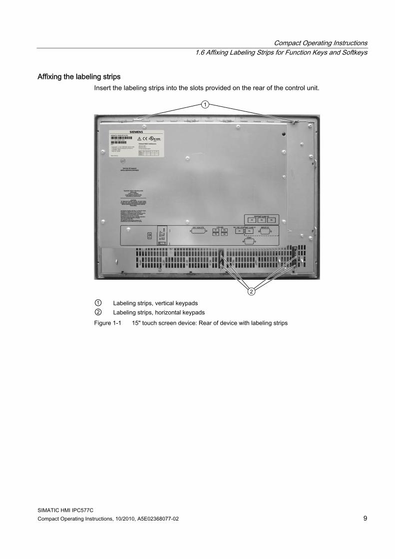
Affixing the labeling strips Insert the labeling strips into the slots provided on the rear of the control unit.
① Labeling strips, vertical keypads ② Labeling strips, horizontal keypads Figure 1-1 15" touch screen device: Rear of device with labeling strips
Compact Operating Instructions 1.7 Installing/Mounting
SIMATIC HMI IPC577C 10 Compact Operating Instructions, 10/2010, A5E02368077-02
1.7 Installing/Mounting
1.7.1 Permitted mounting positions
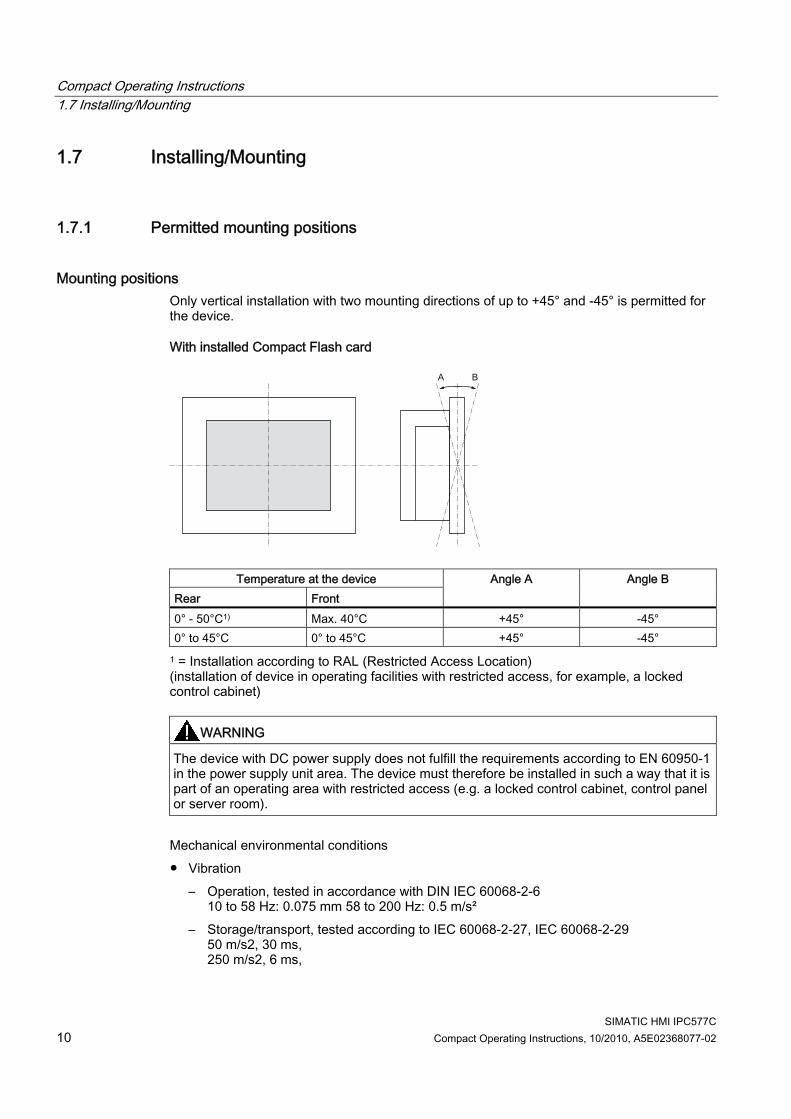
Mounting positions Only vertical installation with two mounting directions of up to +45° and -45° is permitted for the device.
With installed Compact Flash card
Temperature at the device Rear Front
Angle A Angle B
0° - 50°C1) Max. 40°C +45° -45° 0° to 45°C 0° to 45°C +45° -45°
1 = Installation according to RAL (Restricted Access Location) (installation of device in operating facilities with restricted access, for example, a locked control cabinet)
WARNING The device with DC power supply does not fulfill the requirements according to EN 60950-1 in the power supply unit area. The device must therefore be installed in such a way that it is part of an operating area with restricted access (e.g. a locked control cabinet, control panel or server room).
Mechanical environmental conditions ● Vibration
– Operation, tested in accordance with DIN IEC 60068-2-6 10 to 58 Hz: 0.075 mm 58 to 200 Hz: 0.5 m/s²
– Storage/transport, tested according to IEC 60068-2-27, IEC 60068-2-29 50 m/s2, 30 ms, 250 m/s2, 6 ms,

Compact Operating Instructions 1.7 Installing/Mounting
SIMATIC HMI IPC577C Compact Operating Instructions, 10/2010, A5E02368077-02 11
1.7.2 Preparing the mounting cut-out The following illustration shows the dimensions for the mounting cut-out.
(1) Drill hole for screw attachment (4) Clamp (2) Pressure points for clamp (5) RZ 120 in the seal area (3) Setscrews (6) Seal area Figure 1-2 Drill holes for the screws and pressure points for the clamp screws
Note Mounting dimensions can be read from the dimension overview or they can be transferred to the cabinet from the mounting template supplied.

Compact Operating Instructions 1.7 Installing/Mounting
SIMATIC HMI IPC577C 12 Compact Operating Instructions, 10/2010, A5E02368077-02
Table 1- 1 Dimensions for the mounting cut-out in mm
Control unit
L1 L2 L3 1) L4 1) L5 L6 2) L7 2) L8 2) L9 2) A1 A2 S1 S2 S3 S4
S53) S63) S73)
Tolerance ±1 +1 ±0,2 ±0,2 ±0,5 ±0,5 ±0,5 ±0,5 +1 ±1 ±1 ±1 ±1 ±1 ±1 Key panel 12" TFT 15" TFT
450 450
290 321
465 465
235 279
112 112
— 186
— 135
— 25
— 165
16 16
10 17
78 51
78 51
56 56
— —
Touch panel 12" TFT 15" TFT 19" TFT
368 450 450
290 290 380
— 465 465
— 235 235
112 112 112
— — —
— — —
— — —
— — —
16 16 16
10 10 10
19 81 46
35 81 46
56 56 —
— — 46
1) M6 thread or drill holes with a diameter of 7 mm 2) Cut-outs for the shafts of the insert strips are only necessary for 15" key panels. 3) Two clamps necessary for vertically securing clamps only for 19" touch panel fronts.
Preparing the mounting cut-out Steps for preparing the mounting cut-out 1. Select a location suitable for mounting, taking into account the mounting position. 2. On the basis of the dimensions, check whether the required screw and pressure points on the
rear and the seal area are easily accessible after the completion of the mounting cut-out. Otherwise the mounting cut-out is useless.
3. Complete the mounting cut-out in accordance with the dimensions.
1.7.3 Securing the Device with Clamps You require 6 clamps in order to mount the device. These are supplied with the device. Required tool for fasting the clamps: Allen wrench 2.5 mm
Figure 1-3 Clamp assembly
Compact Operating Instructions 1.7 Installing/Mounting
SIMATIC HMI IPC577C Compact Operating Instructions, 10/2010, A5E02368077-02 13
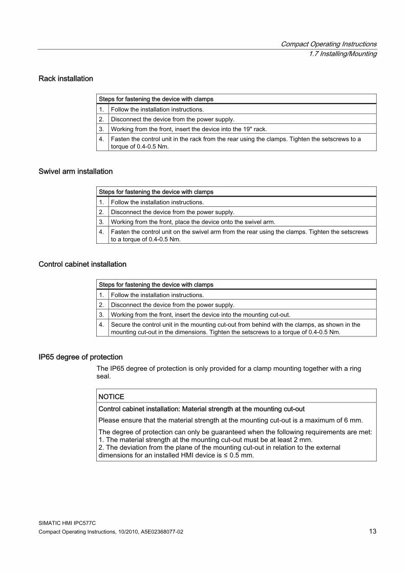
Rack installation Steps for fastening the device with clamps 1. Follow the installation instructions. 2. Disconnect the device from the power supply. 3. Working from the front, insert the device into the 19" rack. 4. Fasten the control unit in the rack from the rear using the clamps. Tighten the setscrews to a
torque of 0.4-0.5 Nm.
Swivel arm installation Steps for fastening the device with clamps 1. Follow the installation instructions. 2. Disconnect the device from the power supply. 3. Working from the front, place the device onto the swivel arm. 4. Fasten the control unit on the swivel arm from the rear using the clamps. Tighten the setscrews
to a torque of 0.4-0.5 Nm.
Control cabinet installation Steps for fastening the device with clamps 1. Follow the installation instructions. 2. Disconnect the device from the power supply. 3. Working from the front, insert the device into the mounting cut-out. 4. Secure the control unit in the mounting cut-out from behind with the clamps, as shown in the
mounting cut-out in the dimensions. Tighten the setscrews to a torque of 0.4-0.5 Nm.
IP65 degree of protection The IP65 degree of protection is only provided for a clamp mounting together with a ring seal.
NOTICE Control cabinet installation: Material strength at the mounting cut-out Please ensure that the material strength at the mounting cut-out is a maximum of 6 mm. The degree of protection can only be guaranteed when the following requirements are met:1. The material strength at the mounting cut-out must be at least 2 mm. 2. The deviation from the plane of the mounting cut-out in relation to the external dimensions for an installed HMI device is ≤ 0.5 mm.
Compact Operating Instructions 1.7 Installing/Mounting
SIMATIC HMI IPC577C 14 Compact Operating Instructions, 10/2010, A5E02368077-02
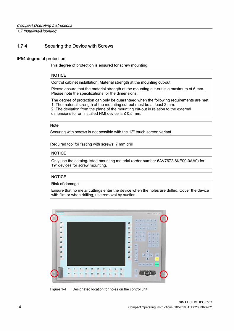
1.7.4 Securing the Device with Screws
IP54 degree of protection This degree of protection is ensured for screw mounting.
NOTICE Control cabinet installation: Material strength at the mounting cut-out Please ensure that the material strength at the mounting cut-out is a maximum of 6 mm. Please note the specifications for the dimensions. The degree of protection can only be guaranteed when the following requirements are met:1. The material strength at the mounting cut-out must be at least 2 mm. 2. The deviation from the plane of the mounting cut-out in relation to the external dimensions for an installed HMI device is ≤ 0.5 mm.
Note Securing with screws is not possible with the 12" touch screen variant.
Required tool for fasting with screws: 7 mm drill
NOTICE Only use the catalog-listed mounting material (order number 6AV7672-8KE00-0AA0) for 19" devices for screw mounting.
NOTICE Risk of damage Ensure that no metal cuttings enter the device when the holes are drilled. Cover the device with film or when drilling, use removal by suction.
Figure 1-4 Designated location for holes on the control unit

Compact Operating Instructions 1.7 Installing/Mounting
SIMATIC HMI IPC577C Compact Operating Instructions, 10/2010, A5E02368077-02 15
Rack installation Steps for fastening the device with screws 1. Follow the installation instructions. 2. Carefully drill the respective holes in the control unit at the designed location from the rear. 3. Working from the front, insert the device into the 19" rack. 4. Secure the control unit by inserting suitable screws through the holes and attaching nuts.
Swivel arm installation Steps for fastening the device with screws 1. Follow the installation instructions. 2. Carefully drill the respective holes in the control unit at the designed location from the rear. 3. Working from the front, place the device onto the swivel arm. 4. Secure the control unit by inserting suitable screws through the holes and attaching nuts.
Control cabinet installation Steps for fastening the device with screws 1. Follow the installation instructions. 2. Drill suitable holes at the prepared installation cut-out in accordance with the specifications for L4
and L5, as shown at the dimensions in the mounting cut-out. 3. Carefully drill the respective holes in the control unit at the designed location from the rear. 4. Working from the front, insert the device into the mounting cut-out. 5. Secure the control unit by inserting suitable screws through the holes and attaching nuts.
Compact Operating Instructions 1.8 Connecting
SIMATIC HMI IPC577C 16 Compact Operating Instructions, 10/2010, A5E02368077-02
1.8 Connecting
1.8.1 Connection elements and operator controls
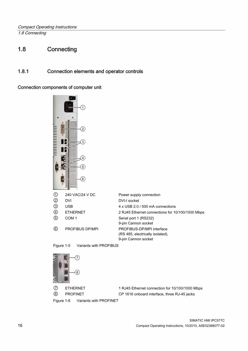
Connection components of computer unit
① 240 VAC/24 V DC Power supply connection ② DVI DVI-I socket ③ USB 4 x USB 2.0 / 500 mA connections ④ ETHERNET 2 RJ45 Ethernet connections for 10/100/1000 Mbps ⑤ COM 1 Serial port 1 (RS232)
9-pin Cannon socket ⑥ PROFIBUS DP/MPI PROFIBUS-DP/MPI interface
(RS 485, electrically isolated), 9-pin Cannon socket
Figure 1-5 Variants with PROFIBUS
⑦ ETHERNET 1 RJ45 Ethernet connection for 10/100/1000 Mbps ⑧ PROFINET CP 1616 onboard interface, three RJ-45 jacks Figure 1-6 Variants with PROFINET

Compact Operating Instructions 1.8 Connecting
SIMATIC HMI IPC577C Compact Operating Instructions, 10/2010, A5E02368077-02 17
Connection components of the control unit
① 1 connection USB 2.0 high current / 500 mA under sealed cover
(not available with every product variant).
NOTICE Ensuring degree of protection P65 When the sealed cover over the USB port is removed in order to connect a USB component, the IP65 degree of protection for the device is no longer guaranteed.
Note Use of USB devices Wait at least ten seconds between removal and reconnection of USB devices. This also
applies to control units with touch screen panels, especially for touch operation. When using standard USB peripherals, bear in mind that their EMC immunity level is
frequently designed for office applications only. These devices may be used for commissioning and servicing. However, only industry-standard devices are allowed for industrial operation.
Peripherals are developed and marketed by individual vendors. The respective manufacturers offer support for the peripherals. Moreover, the terms of liability of the individual vendors or suppliers apply here.
Compact Operating Instructions 1.8 Connecting
SIMATIC HMI IPC577C 18 Compact Operating Instructions, 10/2010, A5E02368077-02
1.8.2 Connecting the 24 VDC power supply
To be noted before you connect the device Note the following in order to operate the device safely and according to regulation:
CAUTION Power is on The On/Off switch does not isolate the device from mains voltage. Always disconnect the power cord to isolate the device from mains voltage.
WARNING The device should only be connected to a 24V DC power supply which satisfies the requirements of safe extra low voltage (SELV). You will also have to connect a protective earth conductor. The cable cross section must withstand the short-circuit current of the 24 VDC power source so that a short-circuit will not damage the cable. Connect only cables with a minimum cross-section of 1.3 mm² (AWG16) and a maximum cross-section of 3.3 mm² (AWG12).
NOTICE The 24V DC power source must be adapted to the input data of the device (see the technical specifications in the operating instructions).
NOTICE If a CompactFlash card is used in the device, make sure that the card is seated correctly before you connect it.

Compact Operating Instructions 1.8 Connecting
SIMATIC HMI IPC577C Compact Operating Instructions, 10/2010, A5E02368077-02 19
Connecting the devices Steps for connecting the device to the 24 V DC power supply 1. Switch off the 24 V DC power source. 2. Connect the DC plug
(1) DC 24 V (2) ground (3) protective conductor
Power consumption The power consumption at 24 V can be up to 90 W, depending on device.
Note equipotential bonding A low-impedance earth connection ensures that interference signals generated by external power supply cables, signal cables or cables to the peripherals are safely discharged to earth. Connect the equipotential bonding as described in section Connecting the equipotential bonding circuit (Page 22).
1.8.3 Connecting the 100 - 240 V AC Power Supply
General connection information Note the following in order to operate the device safely and according to regulation:
Note Voltage range The varying voltage power supply module is designed for operation on 100 to 240 V AC networks. It is not necessary to adjust the voltage range.
NOTICE Risk of damage Do not connect or disconnect power and data cables during thunderstorms.

Compact Operating Instructions 1.8 Connecting
SIMATIC HMI IPC577C 20 Compact Operating Instructions, 10/2010, A5E02368077-02
WARNING Power supply network The device is designed for operation on grounded power supply networks (TN networks to VDE 0100, Part 300, or IEC 60364-3). It is not designed for operation on ungrounded or impedance-grounded power networks (IT networks).
NOTICE Permitted mains voltage The permitted nominal voltage of the device must conform with local mains voltage.
NOTICE Power disconnection The mains connector must be disconnected to fully isolate the device from mains. Ensure easy access to this area. A master mains disconnect switch must be installed if the device is mounted in a switch cabinet. Always ensure free and easy access to the power inlet on the device or that the safety power outlet of the building installation is freely accessible and located close to the device.
NOTICE If a Compact Flash card is used in the device, be sure that the card is properly installed before you connect it.
Note Power Factor Correction The power supply contains an active PFC (Power Factor Correction) circuit to conform to the EMC guidelines. Uninterruptible AC power systems (UPS) must supply a sinusoidal output voltage in the normal and buffered mode when used with SIMATIC PCs with an active PFC. UPS characteristics are described and classified in the standards EN 50091-3 and IEC 62040-3. Devices with sinusoidal output voltage in the normal and buffered mode are identified with the classification "VFI-SS-...." or "VI-SS-....".
Compact Operating Instructions 1.8 Connecting
SIMATIC HMI IPC577C Compact Operating Instructions, 10/2010, A5E02368077-02 21
Country-specific connection information For the USA and Canada: For the United States and Canada, a CSA or UL-listed power cord must be used. The connector must be compliant with NEMA 5-15. Country-specific mains leads are available as accessories. ● 100 V supply voltage
Use a flexible power cord which is approved to UL and CSA, and which has the following features: Type SJT with three leads, min. 18 AWG conductor cross-section, max. length 4.5 m, parallel grounding plug 15 A, min. 125 V.
● 240 V AC supply voltage To be used is a flexible power cord approved to UL and with CSA label, and which has the following features: Type SJT with three conductors, min. 18 AWG conductor cross-section, max. length 4.5 m, and tandem grounded connector 15 A, min. 250 V.
For countries other than the USA and Canada: ● 240 V supply voltage
This device is equipped with a safety-tested power cord which may only be connected to ground contact power outlet. If you choose not to use this cable, you must use a flexible cable of the following type: Min. 18 AWG conductor cross-section and 15 A / 250 V shock-proof connector. The cable set must be compliant with safety regulations and stipulated IDs of the country where the system is to be installed.
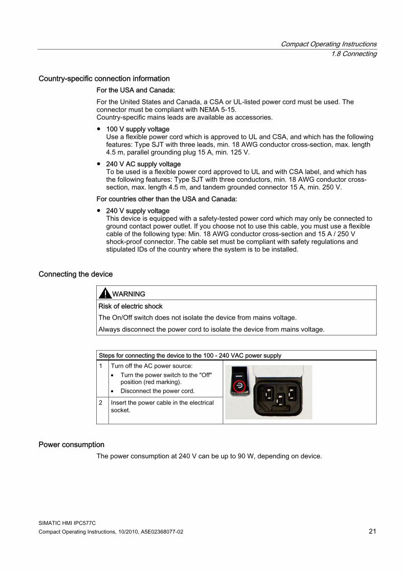
Connecting the device
WARNING Risk of electric shock The On/Off switch does not isolate the device from mains voltage. Always disconnect the power cord to isolate the device from mains voltage.
Steps for connecting the device to the 100 - 240 VAC power supply 1 Turn off the AC power source:
Turn the power switch to the "Off" position (red marking).
Disconnect the power cord.
2 Insert the power cable in the electrical socket.
Power consumption The power consumption at 240 V can be up to 90 W, depending on device.

Compact Operating Instructions 1.8 Connecting
SIMATIC HMI IPC577C 22 Compact Operating Instructions, 10/2010, A5E02368077-02
1.8.4 Connecting the equipotential bonding circuit
Avoiding differences in potential Differences in potential arise between separated system parts, which in some cases leads to high equalization currents. This situation may arise if the cable shielding is, for example, terminated at both ends and grounded at different system parts. Potential differences can be caused, for example, by different power inputs. Reduce the differences in potential by laying the equipotential bonding cables in such a way that the affected electronic components function properly. Observe with the following guidelines when setting up equipotential bonding: ● The lower the impedance of the equipotential bonding cable, the greater the effectiveness
of the equipotential bonding. ● When two system parts are connected by means of a shielded signal cable, and their
shields are both connected to the ground or protected conductor, the following must be observed: The impedance of the additional equipotential bonding cable amounts to 10% of the shield impedance, at the most.
● Make sure that the equipotential bonding cable cross section is selected to accommodate the maximum equalization current.
● Use equipotential bonding conductors made of copper or galvanized steel. Connect the cables to the ground or protective conductor over a wide area. Protect the ground or protective conductor from corrosion.
● Lay the equipotential bonding cable in such a way that the area between the equipotential bonding cable and signal cables is as small as possible.
A low-impedance earth connection ensures that interference signals generated by external power supply cables, signal cables or cables to the peripherals are safely discharged to earth. The connection for the equipotential bonding of the device is located at the connection elements of the computer unit and is identified by the following symbol:
Figure 1-7 Equipotential bonding

Compact Operating Instructions 1.9 Commissioning
SIMATIC HMI IPC577C Compact Operating Instructions, 10/2010, A5E02368077-02 23
Procedure Required tool: TORX T20 screwdriver. Steps for connecting the equipotential bonding 1. Connect the equipotential bonding terminal
(M4 thread) on the device (large surface, large-area contact) with the central grounding point of the control cabinet. The minimum conductor cross-section may not be less than 5 mm2.
1.9 Commissioning
1.9.1 Commissioning Information
Note Initial commissioning of Windows Embedded Standard System startup can take longer than usual for the initial commissioning. Only a blue screen is displayed for several minutes.
NOTICE Windows Embedded Standard: Observe EWF Information Two configurable write filters are available for Windows Embedded Standard, i.e. the EWF (Enhanced Write Filter), or the FBWF (File Based Write Filter). Please observe the EWF rules in the operating instructions during activation and use, since a data loss may otherwise occur.
Note For information about the installation the Compact Flash card for the Windows Embedded Standard operating system, refer to the operating instructions.

Compact Operating Instructions 1.9 Commissioning
SIMATIC HMI IPC577C 24 Compact Operating Instructions, 10/2010, A5E02368077-02
1.9.2 Basic commissioning - initial startup
Requirement ● The device is connected to the power supply. ● The equipotential bonding is connected. ● The cables are correctly plugged in.
Setting up the operating system
Note Initial commissioning of Windows Embedded Standard 2009 System startup can take longer than usual for the initial commissioning. Only a blue screen is displayed for several minutes. The devices with Touch Panel require a USB mouse for commissioning.
On completion of the initial startup of the computer, the operating system on the CompactFlash card, or Solid State Drive (SSD), or hard disk is set up automatically on the computer. Proceed as follows: 1. Switch the device on using the On/Off switch. The PC performs a self-test (POST).
During the self-test, this message appears: Press <F2> to enter SETUP or <ESC> to show the boot menu
2. Wait until this message is cleared, then follow the instructions on the screen.
NOTICE
The device may not be switched off at any time during the installation process. Do not change the default BIOS settings, otherwise the operating system setup may become corrupted.

Compact Operating Instructions 1.9 Commissioning
SIMATIC HMI IPC577C Compact Operating Instructions, 10/2010, A5E02368077-02 25
3. Restart After you have entered all the necessary information and the operating system is configured, you are prompted to restart the system. Acknowledge this prompt with Yes.
Note System startup can take longer than usual for the initial commissioning. The screen will display "FBResseal Resealing in progress..." for several minutes.
Note Errors and warnings can be displayed in the status bar, with the first and second switch on of the initial commissioning or after a restore procedure. This will have no effect on the device functions.
As of now, the operating system automatically opens its user interface immediately upon completion of the startup sequence.
Note To prevent data loss, it is advisable to create an image of your system partition after basic commissioning.
Switching off the device When you work with Windows Embedded Standard, always shut down the PC with the command Start > Shut Down.
Note The Enhanced Write Filter should be enabled following the installation of Windows Embedded Standard on a CompactFlash card, or SSD, or hard disk.
Compact Operating Instructions 1.9 Commissioning
SIMATIC HMI IPC577C 26 Compact Operating Instructions, 10/2010, A5E02368077-02
1.9.3 Setting up the language selection in Windows Embedded Standard 2009 Windows Embedded Standard 2009 offers the option of selecting the menu and dialog languages. You can select the German and English languages.
Setting up the language selection Windows Embedded Standard 2009 is set up by default with English menu and dialog language and US international keyboard layout. You can change the language in the Control Panel by selecting:
Start > Settings > Control Panel >Regional and Language Options > Languages tab, Language used in menus and dialogs field. In addition to the menu and dialog language, select Regional and Language Options and set the default to non-Unicode programs in the Advanced section.
1.9.4 Language selection in Windows Embedded Standard 7 Changing languages is possible using the Restore CD/DVD (forms part of the scope of delivery). The CD/DVD contains the required language packages and help for changing the system language.
Note Note the license terms of Windows Embedded Standard 7 Please note the license terms for Windows Embedded Standard 7 and especially the extended SIEMENS AG Software terms for Windows Embedded Standard 7. You can find the license terms in the delivered document "MICROSOFT SOFTWARE LICENSE TERMS for Windows Embedded Standard 7(E)" and in the system drive under \Windows\System32\license.rtf.
Change system language To change the language for Windows Embedded Standard 7, follow these steps: Prerequisite: The "Legacy USB Support" option has to be set to "Enabled" in the Advanced menu of the BIOS so that the device can address a USB CD-ROM drive. 1. Connect a USB CD-ROM drive to the device. 2. Insert the Restore CD/DVD in the drive, restart the device and when the BIOS message:
Press <F2> to enter Setup or <ESC> to show Boot menu appears, press the F2 key.
3. Select the Boot menu and move the entry "CD-ROM Drive" to the first position. 4. End the BIOS setup with the "Exit Saving Changes" entry.

Compact Operating Instructions 1.9 Commissioning
SIMATIC HMI IPC577C Compact Operating Instructions, 10/2010, A5E02368077-02 27
5. Follow the on-screen instructions. 6. After selecting the menu dialog language of the Restore CD/DVD, select the menu entry
"Select language packages". Depending on the current language setup, you have the following options in the "Select language packages" menu: – Display language settings – Install language – Change language – Remove the "Non-system language".
Note The "Install language or Deinstall language" process can take several minutes.
Note The "Legacy USB Support" option has to be set to "Enabled" in the Advanced menu of the BIOS so that the device can address a USB CD-ROM drive.
Compact Operating Instructions 1.9 Commissioning
SIMATIC HMI IPC577C 28 Compact Operating Instructions, 10/2010, A5E02368077-02
1.9.5 Setting the panel type
1.9.5.1 First commissioning
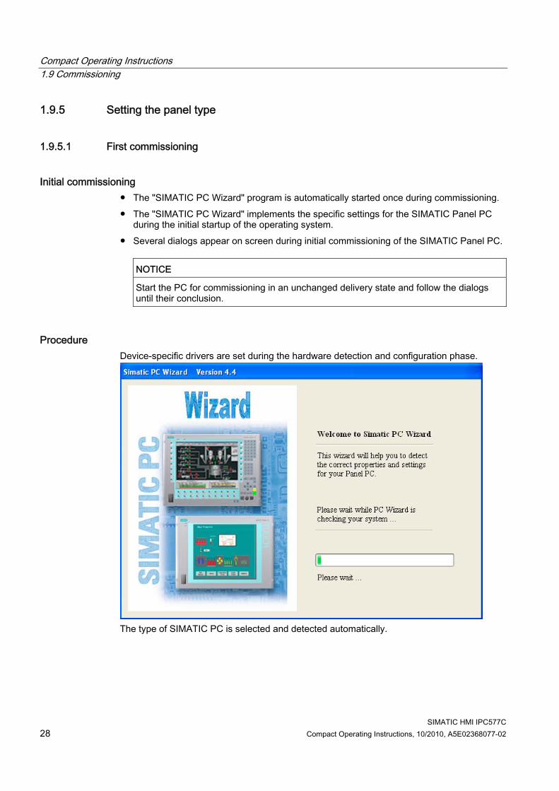
Initial commissioning ● The "SIMATIC PC Wizard" program is automatically started once during commissioning. ● The "SIMATIC PC Wizard" implements the specific settings for the SIMATIC Panel PC
during the initial startup of the operating system. ● Several dialogs appear on screen during initial commissioning of the SIMATIC Panel PC.
NOTICE
Start the PC for commissioning in an unchanged delivery state and follow the dialogs until their conclusion.
Procedure Device-specific drivers are set during the hardware detection and configuration phase.
The type of SIMATIC PC is selected and detected automatically.

Compact Operating Instructions 1.9 Commissioning
SIMATIC HMI IPC577C Compact Operating Instructions, 10/2010, A5E02368077-02 29
1.9.5.2 Touch panel configuration
Touch screen calibration 1. Calibrate the touch screen by clicking the wizard.
2. Click "Finish".
Compact Operating Instructions 1.9 Commissioning
SIMATIC HMI IPC577C 30 Compact Operating Instructions, 10/2010, A5E02368077-02
Note On-screen keyboard (OSK) If the "enable" checkbox is selected, the Windows on-screen keyboard is displayed for
logon at every program start. You can use this keyboard to enter the administrator password, for example. An external keyboard is then not necessary.
If you clear the checkbox, the on-screen keyboard is not displayed. In Windows 7, the on-screen keyboard is not displayed until a password is assigned to
the user account.
3. Use the "Finish" button to close the wizard. The HMI device will be restarted automatically for the respective configuration.
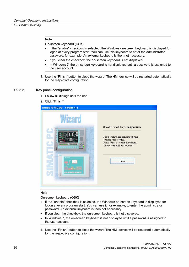
1.9.5.3 Key panel configuration 1. Follow all dialogs until the end. 2. Click "Finish".
Note On-screen keyboard (OSK) If the "enable" checkbox is selected, the Windows on-screen keyboard is displayed for
logon at every program start. You can use it, for example, to enter the administrator password. An external keyboard is then not necessary.
If you clear the checkbox, the on-screen keyboard is not displayed. In Windows 7, the on-screen keyboard is not displayed until a password is assigned to
the user account.
1. Use the "Finish" button to close the wizard.The HMI device will be restarted automatically for the respective configuration.

Compact Operating Instructions 1.9 Commissioning
SIMATIC HMI IPC577C Compact Operating Instructions, 10/2010, A5E02368077-02 31
1.9.5.4 Automatic restart An automatic restart is perfumed after every configuration.
1.9.6 Device with key panel
1.9.6.1 Activating KeyTools SIMATIC KeyTools is one selection of the applications for SIMATIC Panel PC. These applications allow you to adapt key codes that are sent by the key panel of the control unit. SIMATIC KeyTools consists of the following applications: ● Key code table: Loading and editing of key code tables. ● WinCC hotkey function: WinCC hotkey function activation und deactivation. ● Security features: Lock function that prevents two function keys from being activated
simultaneously. This prevents incorrect operations and undefined states of the application program.
Note For a detailed description of the SIMATIC KeyTools, refer to the help menu and the application description on the Documentation & Drivers DVD.

Compact Operating Instructions 1.9 Commissioning
SIMATIC HMI IPC577C 32 Compact Operating Instructions, 10/2010, A5E02368077-02
Opening Keytools 1. Open Keytools with the command Start > Settings > Control Panel > SIMATIC KeyTools. 2. Select the desired application and follow the instructions on the screen.
NOTICE Malfunctions of the user software For security reasons always use the "Security features". If you deactivate it nevertheless, serious malfunctions of the user software may occur when the additional function keys and softkeys F13 to S16 are used or if own key code tables are used.
1.9.7 Device with touch screen
1.9.7.1 Recalibrating the Touch Screen If the touch screen does not react as expected when touched, repeat the calibration.
Procedure for standard calibration 1. Select "Start > Programs > UPDD > Settings".
The "UPDD Console" dialog box opens.
Figure 1-8 Point calibration
2. Select the controller ① you wish to calibrate.

Compact Operating Instructions 1.9 Commissioning
SIMATIC HMI IPC577C Compact Operating Instructions, 10/2010, A5E02368077-02 33
3. Click the "Calibration" tab ②.
4. Select the "Number of points" option with the "25 point calibration" ③.
5. Click "Calibrate" ④.
The calibration mask is output on the selected display. 6. Quickly touch the corresponding selections one after the other.
The entry is confirmed by a check mark, the next selection is displayed. 7. Confirm all input prompts (arrows, or crosses in the center) until the complete screen has
been calibrated. 8. Finally, confirm the prompt with "Confirm".
Procedure for EEPROM calibration 1. Select "Start > Programs > UPDD > Settings".
The "UPDD Console" dialog box opens.
Figure 1-9 Point calibration
2. Select the controller ① you wish to calibrate.
3. Click the "Calibration" tab ②.
The "Use eeprom storage" ⑤ option is selected by default for touch controllers with EEPROM.
The "Number of points" option box indicates "3-point calibration" ③.
4. Click "Calibrate" ④.
The calibration mask is output on the selected display.

Compact Operating Instructions 1.9 Commissioning
SIMATIC HMI IPC577C 34 Compact Operating Instructions, 10/2010, A5E02368077-02
5. Quickly touch the corresponding selections one after the other. The entry is confirmed by a check mark, the next selection is displayed.
6. Confirm all input prompts (arrows, or crosses in the center) until the complete screen has been calibrated.
Note If the screen does not respond to touching as expected, check the specified controller (marked in black) in "UPDD Console" and repeat the calibration. Only an active controller can be calibrated. A removed controller is marked in red. If 3 point calibration does not suffice for the operator panel, you can clear it in the "Use eeprom storage" option box and use the standard calibration (25 point calibration). Currently only the Touch Controller "ELO 2216 (USB)" supports EEPROM calibration.
Extended Touch touch functionality 1. Select "Start > Programs > UPDD > Settings". The "UPDD Console" dialog box opens.
2. Select the corresponding controller.

Compact Operating Instructions 1.9 Commissioning
SIMATIC HMI IPC577C Compact Operating Instructions, 10/2010, A5E02368077-02 35
The "Extended touch" option is preset for Windows 7.
Note The "Extended touch" functionality is only available for Windows 7 Ultimate. If "Extended touch" is selected, the extended touch functions of Windows 7 will be available, such as "operating touch permanently", which corresponds to the right mouse button function.
Note The "EventSelector" program works only with disabled "Extended touch" function.
1.9.7.2 Activating the Screen Keyboard You can operate the device by means of a virtual screen keyboard. You can use it to enter the characters directly on the touch screen or with the mouse.
Starting Touch Input Start the "Touch Input" application on the desktop. The screen keyboard is displayed.
(1) Button for language selection: German, English, Italian, Spanish, French

Compact Operating Instructions 1.10 Service and support
SIMATIC HMI IPC577C 36 Compact Operating Instructions, 10/2010, A5E02368077-02
1.10 Service and support
Local information Contain your Siemens representative (http://www.siemens.com/automation/partner) if you have questions about the products described here.
Technical documentation for SIMATIC products You can find additional documentation for SIMATIC products and systems in the Internet: SIMATIC Guide manuals (http://www.siemens.com/simatic-tech-doku-portal)
Easy shopping at the mall You can find the online catalog and order system under: Industrial Automation and Drive Technologies (http://mall.automation.siemens.com)
Training center All the training options are listed at: SITRAIN homepage (http://www.sitrain.com)
Technical support You can contact technical support for all Industry Automation and Drive Technologies products by: ● E-mail: [email protected] ● Internet: Online support request form:
(http://www.siemens.com/automation/support-request) When you contact the customer support, please have the following information for the technician on hand: ● BIOS version ● Order No. (MLFB) of the device ● Installed additional software ● Installed additional hardware
Online Service & Support Information about the product, Support and Service, right through to the Technical Forum, can be found at: Industry Automation and Drive Technologies - Homepage (http://www.siemens.com/automation/service&support)
After-sales information system for SIMATIC PC / PG Information about contacts, drivers, and BIOS updates, FAQs and Customer Support can be found at: After-sales information system for SIMATIC PC/PG (http://www.siemens.com/asis)

SIMATIC HMI IPC577C Compact Operating Instructions, 10/2010, A5E02368077-02 37
Index
A Accessories, 7
C Clamp, 12 Configuration, 7 Control cabinet installation, 13, 15
D Degree of protection
IP54, 14 IP65, 13
E EEPROM calibration, 33 Equipotential bonding, 23
I Initial commissioning
for Windows Embedded Standard, 24 SIMATIC PC Wizard, 28
L Labeling strips, 8 Language selection
Setup in Windows Embedded Standard 2009, 26
M Mounting, 13 Mounting positions, 10
O Operating system
Setting up Windows Embedded Standard, 24
P Panel Wizard
starting, 28 Power disconnection, 20 Power Factor Correction, 20 Power supply, 18
R Rack installation, 13, 15
S Screen keyboard
calling, 35 SIMATIC KeyTools, 31 SIMATIC PC Wizard
Initial commissioning, 28 Standard calibration, 32 Supply voltage, 18, 21 Swivel arm installation, 13, 15
T Touch input
Calling the screen keyboard, 35
V Voltage range, 19
W Windows Embedded Standard
Setting up the operating system, 24 Wiring information, 21

Index
SIMATIC HMI IPC577C 38 Compact Operating Instructions, 10/2010, A5E02368077-02
![stest1.etnetera.czstest1.etnetera.cz/ad/current/content/data_files/automatizacni... · 8quhvwulfwhg .rqwdnw\ 'lvwulexwr 7l 7d]hqt goh dehfhg\ plnurv\vwpp\ y nxvryïfk pqr uvwytfk](https://static.fdocuments.net/doc/165x107/5c173d5d09d3f263628d5b6c/-8quhvwulfwhg-rqwdnw-lvwulexwr-7l-7dhqt-goh-dehfhg-plnurvvwpp-y-nxvryifk.jpg)