Sikker: A High-Performance Distributed System Architecture...
12
CVA Memo #138 Sikker: A High-Performance Distributed System Architecture for Secure Service-Oriented Computing Nicholas McDonald and William J. Dally Stanford University {nmcdonal,dally}@stanford.edu ABSTRACT In this paper, we present Sikker 1 , a high-performance dis- tributed system architecture for secure service-oriented com- puting. Sikker includes a novel service-oriented application model upon which security and isolation policies are derived and enforced. The workhorse of Sikker is a custom network interface controller, called the Network Management Unit (NMU), that enforces Sikker’s security and isolation poli- cies while providing high-performance network access. Sikker’s application model satisfies the complex interac- tions of modern large-scale distributed applications. Our ex- perimentation results show that even when implemented on very large clusters, the NMU adds a negligible message la- tency of 41 ns under realistic workloads and 66 ns at the 99 th percentile of worst case access patterns. Our analysis shows that the NMU can easily support over 100 Gbps with a single logic engine and that over 500 Gbps is achievable with more aggressive designs. Sikker’s service-oriented security and isolation mechanism removes high overheads imposed by current systems. Sikker allows distributed applications to operate in an environment with fine-grained security and isolation while experiencing supercomputer-like network performance. 1. INTRODUCTION The number and variety of applications and services run- ning in modern data centers, cloud computing facilities, and supercomputers has driven the need for a secure computing platform with an intricate network isolation and security pol- icy. Traditionally, supercomputers focused on performance at the expense of internal network security while data centers and cloud computing facilities focused on cost efficiency, flexibility, and TCP/IP compatibility all at the expense of performance. In spite of their historical differences, the re- quirements of these computing domains are beginning to converge. With increased application complexity, data cen- ters and cloud computing facilities require higher network bandwidth and predictably low latency. As supercomputers become more cost sensitive and are simultaneously utilized 1 Sikker is a danish translation for “safe” by many clients, they require a higher level of application isolation and security. The advent of cloud-based supercom- puting [3, 18] brings these domains even closer by merging them onto the same network. Operating under a single administrative domain allows distributed systems to consider the network a trusted entity and rely on its features. Supercomputers use this ideology to achieve ultimate performance, however, they maintain min- imal security and isolation mechanisms. In contrast, cloud computing facilities achieve high levels of security and iso- lation at the expense of much lower performance. In theory, a single administrative domain could provide simultaneous performance, security, and isolation as these are not funda- mentally in opposition. The unfortunate truth is that modern network technologies have not provided distributed systems that are capable of supercomputer-like network performance while simultaneously providing robust application security and isolation. As a result, system designers and application developers are forced to make trade-offs leaving deficiencies in their system and creating high development and runtime overheads. In this paper, we present a new distributed system archi- tecture called Sikker, that includes an explicit security and isolation policy. The goal of this system is to provide the highest level of network performance while enforcing the highest level of application security and isolation required by the complex interactions of modern large-scale applica- tions. Sikker formally defines a distributed application as a collection of distributed services with well-defined interac- tion policies. Sikker utilizes specially architected network interface controllers (NICs), called Network Management Units (NMUs), to enforce application security and isolation policies while providing efficient network access. Unlike common NICs, NMUs operate directly under the control of a system-wide Network Operating System (NOS), and as such, are not vulnerable to compromises of individual host operating systems. This paper makes the following contributions: • We present a new distributed system security and iso- lation model that is built from a service-oriented ac- cess control list methodology. This is the first work
Transcript of Sikker: A High-Performance Distributed System Architecture...

CVA Memo #138
Sikker: A High-Performance Distributed SystemArchitecture for Secure Service-Oriented Computing
Nicholas McDonald and William J. Dally
Stanford University
{nmcdonal,dally}@stanford.edu
ABSTRACTIn this paper, we present Sikker1, a high-performance dis-tributed system architecture for secure service-oriented com-puting. Sikker includes a novel service-oriented applicationmodel upon which security and isolation policies are derivedand enforced. The workhorse of Sikker is a custom networkinterface controller, called the Network Management Unit(NMU), that enforces Sikker’s security and isolation poli-cies while providing high-performance network access.
Sikker’s application model satisfies the complex interac-tions of modern large-scale distributed applications. Our ex-perimentation results show that even when implemented onvery large clusters, the NMU adds a negligible message la-tency of 41 ns under realistic workloads and 66 ns at the 99th
percentile of worst case access patterns. Our analysis showsthat the NMU can easily support over 100 Gbps with a singlelogic engine and that over 500 Gbps is achievable with moreaggressive designs.
Sikker’s service-oriented security and isolation mechanismremoves high overheads imposed by current systems. Sikkerallows distributed applications to operate in an environmentwith fine-grained security and isolation while experiencingsupercomputer-like network performance.
1. INTRODUCTIONThe number and variety of applications and services run-
ning in modern data centers, cloud computing facilities, andsupercomputers has driven the need for a secure computingplatform with an intricate network isolation and security pol-icy. Traditionally, supercomputers focused on performanceat the expense of internal network security while data centersand cloud computing facilities focused on cost efficiency,flexibility, and TCP/IP compatibility all at the expense ofperformance. In spite of their historical differences, the re-quirements of these computing domains are beginning toconverge. With increased application complexity, data cen-ters and cloud computing facilities require higher networkbandwidth and predictably low latency. As supercomputersbecome more cost sensitive and are simultaneously utilized1Sikker is a danish translation for “safe”
by many clients, they require a higher level of applicationisolation and security. The advent of cloud-based supercom-puting [3, 18] brings these domains even closer by mergingthem onto the same network.
Operating under a single administrative domain allowsdistributed systems to consider the network a trusted entityand rely on its features. Supercomputers use this ideology toachieve ultimate performance, however, they maintain min-imal security and isolation mechanisms. In contrast, cloudcomputing facilities achieve high levels of security and iso-lation at the expense of much lower performance. In theory,a single administrative domain could provide simultaneousperformance, security, and isolation as these are not funda-mentally in opposition. The unfortunate truth is that modernnetwork technologies have not provided distributed systemsthat are capable of supercomputer-like network performancewhile simultaneously providing robust application securityand isolation. As a result, system designers and applicationdevelopers are forced to make trade-offs leaving deficienciesin their system and creating high development and runtimeoverheads.
In this paper, we present a new distributed system archi-tecture called Sikker, that includes an explicit security andisolation policy. The goal of this system is to provide thehighest level of network performance while enforcing thehighest level of application security and isolation requiredby the complex interactions of modern large-scale applica-tions. Sikker formally defines a distributed application as acollection of distributed services with well-defined interac-tion policies. Sikker utilizes specially architected networkinterface controllers (NICs), called Network ManagementUnits (NMUs), to enforce application security and isolationpolicies while providing efficient network access. Unlikecommon NICs, NMUs operate directly under the control ofa system-wide Network Operating System (NOS), and assuch, are not vulnerable to compromises of individual hostoperating systems.
This paper makes the following contributions:
• We present a new distributed system security and iso-lation model that is built from a service-oriented ac-cess control list methodology. This is the first work

to present a service-oriented network architecture andprocess-oriented authentication.
• We show how modern large-scale applications fit intothis model and how they can be modified to make useof it.
• We present the Network Management Unit, a high per-formance network interface controller that, under thedirection of a Network Operating System, enforces thesecurity and isolation policies of Sikker.
• We provide an evaluation of Sikker and the NMU whichshows that it simultaneously provides high performancenetwork access and robust application security and iso-lation.
The outline of this paper is as follows. In Section 2 wediscuss the motivation of Sikker in terms of performanceand application structure and propose a new methodologyfor implementing access control. In Section 3 we describethe Sikker architecture as an abstract system with strict re-quirements and plentiful features. In Section 4 we presentthe Network Management Unit as the device that enablesSikker to operate as described with high performance. Sec-tion 5 describes our evaluation methodology and Section 6shows the evaluation results of Sikker and the NMU. Section7 presents prior related work and in Section 8 we conclude.
2. MOTIVATION
2.1 Attainable PerformanceThe highest level of network performance available today
is found in supercomputing interconnection networks suchas Cray Cascade [14] and Gemini [1], IBM Blue Gene/Q[12] and PERCS [5], and Mellanox InfiniBand [24]. Theseinterconnects achieve high bandwidth and predictably lowlatency while incurring minimal CPU overhead. For exam-ple, InfiniBand networks manufactured by Mellanox Tech-nologies achieve round-trip times on the order of 2 µs andbandwidths as high as 100 Gbps [24]. The Cray Cascadesystem achieves unidirectional latencies as low as 500 ns andprovides 93.6 Gbps of global bisection bandwidth per node[14]. In order to achieve our goal of high network perfor-mance, we define our metrics for performance relative to thehighest performing interconnection networks.
One of the major strategies that supercomputers use toachieve high performance is allowing applications to by-pass the operating system and interact with the network in-terface directly. This is called OS-bypass. All major highperformance computing fabrics (e.g. Cray, IBM, Mellanox,Myricom, Quadrics) have taken this approach. Along withproviding lower and more predictable network latency, OS-bypass provides lower CPU overhead as the kernel is freed ofthe task of managing network interface sharing. CPU over-head can be further reduced by offloading network transportprotocols to the network interface.
OS-bypass has one major ramification, namely, bypass-ing the kernel (or hypervisor) removes its ability to monitor,modify, rate limit, or block outgoing network traffic in an ef-fort to provide sender-side security and isolation features asis commonly performed in network virtualization software.
Ads Email DB
Blog Cache
PostDBMailHTTP
HTTP
Figure 1: High level service connectivity. Directed edgesshow direction of functionality offering.
2.2 Service-Oriented ApplicationsModern large-scale distributed applications are often com-
prised of thousands of processes. For reasons of manage-ment, separation of development, modularity, and fault tol-erance, these processes are grouped by similarity into collec-tions called services. A service is a collection of processesdeveloped and executed for the purpose of implementing asubset of an application’s functionality. Applications can becomprised of one or more services, often tens or hundreds,and services are often shared between many applications.Figure 1 shows a simplified diagram of six services interact-ing to fulfill the functionality of two user facing applications,an email system and a blogging system. Each service has adefined application programming interface (API) that it ex-poses to provide functionality to other services. Even thougha modern data center might contain thousands of services,each service generally communicates with a small subset ofthe total services in order to fulfill its designed functionality.Furthermore, it is common for a service to use only a portionof another service’s API.
Figure 2 is a diagram created by Twitter to illustrate theoperation of their protocol-agnostic communication system.Similarly, Figure 3 is a diagram created by Netflix illustrat-ing their architecture on Amazon’s cloud computing plat-form. For both of these designs, there exists several servicescustom written for the application, as well as several ser-vices written by third-parties. Both of these diagrams showthat when designing an application at a high level, appli-
Figure 2: Twitter’s Finagle RPC system[42].
2
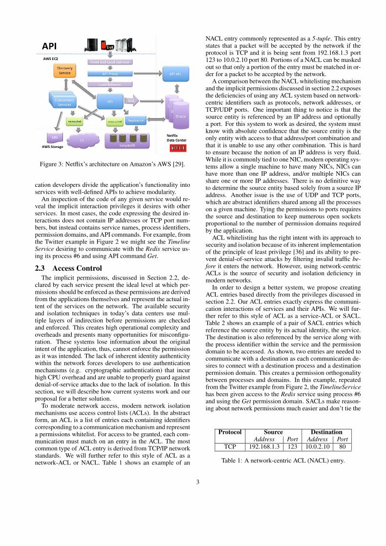
Figure 3: Netflix’s architecture on Amazon’s AWS [29].
cation developers divide the application’s functionality intoservices with well-defined APIs to achieve modularity.
An inspection of the code of any given service would re-veal the implicit interaction privileges it desires with otherservices. In most cases, the code expressing the desired in-teractions does not contain IP addresses or TCP port num-bers, but instead contains service names, process identifiers,permission domains, and API commands. For example, fromthe Twitter example in Figure 2 we might see the TimelineService desiring to communicate with the Redis service us-ing its process #6 and using API command Get.
2.3 Access ControlThe implicit permissions, discussed in Section 2.2, de-
clared by each service present the ideal level at which per-missions should be enforced as these permissions are derivedfrom the applications themselves and represent the actual in-tent of the services on the network. The available securityand isolation techniques in today’s data centers use mul-tiple layers of indirection before permissions are checkedand enforced. This creates high operational complexity andoverheads and presents many opportunities for misconfigu-ration. These systems lose information about the originalintent of the application, thus, cannot enforce the permissionas it was intended. The lack of inherent identity authenticitywithin the network forces developers to use authenticationmechanisms (e.g. cryptographic authentication) that incurhigh CPU overhead and are unable to properly guard againstdenial-of-service attacks due to the lack of isolation. In thissection, we will describe how current systems work and ourproposal for a better solution.
To moderate network access, modern network isolationmechanisms use access control lists (ACLs). In the abstractform, an ACL is a list of entries each containing identifierscorresponding to a communication mechanism and representa permissions whitelist. For access to be granted, each com-munication must match on an entry in the ACL. The mostcommon type of ACL entry is derived from TCP/IP networkstandards. We will further refer to this style of ACL as anetwork-ACL or NACL. Table 1 shows an example of an
NACL entry commonly represented as a 5-tuple. This entrystates that a packet will be accepted by the network if theprotocol is TCP and it is being sent from 192.168.1.3 port123 to 10.0.2.10 port 80. Portions of a NACL can be maskedout so that only a portion of the entry must be matched in or-der for a packet to be accepted by the network.
A comparison between the NACL whitelisting mechanismand the implicit permissions discussed in section 2.2 exposesthe deficiencies of using any ACL system based on network-centric identifiers such as protocols, network addresses, orTCP/UDP ports. One important thing to notice is that thesource entity is referenced by an IP address and optionallya port. For this system to work as desired, the system mustknow with absolute confidence that the source entity is theonly entity with access to that address/port combination andthat it is unable to use any other combination. This is hardto ensure because the notion of an IP address is very fluid.While it is commonly tied to one NIC, modern operating sys-tems allow a single machine to have many NICs, NICs canhave more than one IP address, and/or multiple NICs canshare one or more IP addresses. There is no definitive wayto determine the source entity based solely from a source IPaddress. Another issue is the use of UDP and TCP ports,which are abstract identifiers shared among all the processeson a given machine. Tying the permissions to ports requiresthe source and destination to keep numerous open socketsproportional to the number of permission domains requiredby the application.
ACL whitelisting has the right intent with its approach tosecurity and isolation because of its inherent implementationof the principle of least privilege [36] and its ability to pre-vent denial-of-service attacks by filtering invalid traffic be-fore it enters the network. However, using network-centricACLs is the source of security and isolation deficiency inmodern networks.
In order to design a better system, we propose creatingACL entries based directly from the privileges discussed insection 2.2. Our ACL entries exactly express the communi-cation interactions of services and their APIs. We will fur-ther refer to this style of ACL as a service-ACL or SACL.Table 2 shows an example of a pair of SACL entries whichreference the source entity by its actual identity, the service.The destination is also referenced by the service along withthe process identifier within the service and the permissiondomain to be accessed. As shown, two entries are needed tocommunicate with a destination as each communication de-sires to connect with a destination process and a destinationpermission domain. This creates a permission orthogonalitybetween processes and domains. In this example, repeatedfrom the Twitter example from Figure 2, the TimelineServicehas been given access to the Redis service using process #6and using the Get permission domain. SACLs make reason-ing about network permissions much easier and don’t tie the
Protocol Source DestinationAddress Port Address Port
TCP 192.168.1.3 123 10.0.2.10 80
Table 1: A network-centric ACL (NACL) entry.
3

Source DestinationService Service Process Domain
TimelineService Redis 6 -TimelineService Redis - Get
Table 2: Example service-oriented ACL entry (SACL).
permission system to any underlying transport protocol oraddressing scheme. It simply enforces permissions in theirnatural habitat, the application layer.
A tremendous amount of security and isolation benefitsare available to the endpoints if the following system-levelrequirements are upheld for the SACL methodology:
SACL Requirements:.
S.1 The network is a trusted entity and no endpoint hascontrol over it.
S.2 The network is able to derive the identity of a processand it is impossible for a process to falsify its identity.
S.3 The source (sender) identifier is sent with each mes-sage to the destination (receiver).
S.4 Messages sent are only received by the specified desti-nation entity.
With these requirements upheld, the system inherently im-plements source authentication by which all received mes-sages explicitly state the source entity’s identification. Des-tination authentication is also inherent by the same logic.Combined, source and destination authentication remove theneed for complex authentication software in the applicationlayer. Furthermore, senders don’t need to use name serversto discover physical addressing for desired destinations asthey only need to specify the destination by its virtual iden-tity (i.e. service ID, process ID, and domain ID) and thenetwork will deliver the message to the proper physical lo-cation.
3. SIKKER
3.1 Application ModelWith the insights gained in section 2, we define a new
distributed system architecture, called Sikker, that formallydefines the structure of distributed applications. Sikker isstrictly a service-oriented architecture and makes no attemptto justify the boundaries of applications. As a service-orientedarchitecture, Sikker designates the service as the fundamen-tal building block of distributed applications.
Each service in Sikker contains a set of processes as itsexecution units that implement a common API. A processcan be an OS process, software container, virtual machine,etc. Each process within a service is assigned a numericalID unique to the service.
The API of each service in Sikker contains a set of permis-sion domains, subsequently referred to as domains. Each do-main represents a portion of the service’s functionality withrespect to a specific permission. Sikker domains are not used
H1
S1:P1
S1
S1:D2
S1:D1
S3:P1
H2
S2:P1
S2
S3:P2
S2:D1
H4
S3:D2
S3
S3:D1S3:P3
H5
H3
S1:P2
S1:D3
=Service =Process =Domain =Host
Figure 4: An example service interaction graph. Solid edgesrepresent assignment and dashed edges represent permis-sions.
for multiplexing, are not shared, and are only used to spec-ify a destination. Each service has its own domain numberspace, thus, two services using the same domain ID is ac-ceptable.
To understand the usage of Sikker domains, consider asimple key/value storage service that exposes functionalityto perform data retrieval like the “get” command in mem-cached or Redis. Assuming that the service only allows usersto access their own data and not data stored by other clients,the service would need to define a domain for the data re-trieval function per client. Thus, for a system with threeclients there would be three domains for the “get” function-ality, one for each user’s data. This example shows how aservice might tie its specific API commands to domains. Analternative is to group the API commands into access types(e.g. read and write) which results in fewer total domains.Another alternative is to only create one domain per user.All these are acceptable schemes in Sikker but will yield dif-ferent granularities on which security and isolation can beenforced.
Figure 4 is an example of service interactions under theSikker application model. This diagram shows three ser-vices, each with a few processes and a few domains. Solidlines connect services to their corresponding processes anddomains as well as connect processes to their correspond-ing hosts. As shown, and widely used in practice, processesfrom the same service and/or different services may overlapon the same host. Dashed lines show the permissions givento services. These lines originate at a service and end at aprocess or a domain.
Each process within a service inherits all the permissionsof the service to which it belongs. In order a process to beable to transmit a message to a specific destination, the ser-vice of the sending process must have permission to accessthe specified process and domain within the specified des-
4

tination service. Sikker performs permission checks beforemessages enter the network and for every message. Becausethe interaction policies of modern large-scale distributed sys-tems are constantly in flux, Sikker allows processes and do-mains to be added and removed from services dynamicallyduring runtime. When a new process is created, it inheritsall the permissions of the service to which it belongs. Anytime the permissions of a given service change, the changeis reflected in all processes of the service.
3.2 AuthenticationAll communication in Sikker is explicitly authenticated
at the source and destination. Similar to other networks,processes in Sikker reside at physical locations specified byphysical addresses. However, in Sikker, processes are refer-enced by virtual addresses that specify both the service andthe process. When a process desires to send a message on thenetwork, it does not specify its own identity as the source.Instead, Sikker derives its identity, consisting of both serviceand process, and attaches it to the message.
When specifying a destination for a message, the sourceprocess specifies the destination by three things: a service,a process within the service, and a domain within the ser-vice. Combined, the source and destination specificationsare attached to every message transmitted on the network.Sikker guarantees that the message will only be deliveredto the specified destination. Receiving processes are able toinspect the source specification in the message to explicitlyknow the source’s identity.
Under the Sikker security model, processes need not beconcerned about physical addressing in the network. Pro-cesses only use service-oriented virtual network addresseswhen referencing each other. Sikker performs the virtual-to-physical translations needed for transmission on the net-work. There is no need for name servers in Sikker.
3.3 One-Time-PermissionsThe use of request-response protocols are ubiquitous in
service-oriented applications. In this environment, many ser-vices only become active when they receive requests fromother services. This master/slave interaction is achieved viarequest-response protocols. Cloud computing providers of-ten provide services like this with many features to increasethe productivity of their tenants. These services (e.g. Ama-zon S3[4], Google BigTable[11], Microsoft Azure Search[26])can be very large and provide functionality to many thou-sands of clients.
To increase scalability and to fit better with large-scalerequest-response driven multi-tenant systems, Sikker con-tains a mechanism for one-time-permissions (OTPs). AnOTP is a permission generated by one process and given toanother process to be used only once. An OTP specifies aservice, process, and domain as a destination and can onlybe created using the permissions that the creating process al-ready has. When a process receives an OTP from anotherprocess, it is stored by Sikker in a temporary storage areauntil it gets used by the process, at which time Sikker au-tomatically deletes the permission. Because an OTP fully
specifies the destination, the process using it specifies theOTP by its unique ID instead of specifying the destinationas a service, process, and domain. Only the process that re-ceived the OTP can use it. OTPs cannot be shared across theprocesses in a service.
For an example of using OTPs, consider Service 1 in Fig-ure 4 which has no permissions assigned to it, thus, cannotsend messages on the network. Assume this service is a sim-ple in-memory cache service. Its API specifies that users ofthe service must give it an OTP with each request. Nowassume that Service 2 Process 1 (S2,P1) wishes to send a re-quest to Service 1 Process 2 Domain 1 (S1,P2,D1). Whenit formulates its request, it generates an OTP that specifiesitself (S2,P1) with Domain 1 as the recipient (S2,P1,D1).(S1,P2) will receive the OTP with the request and when theresponse is ready to be sent, it simply uses the OTP to sendit. After the response is sent, Sikker deletes the OTP.
Another interesting example of using OTPs is allowingone service to act on behalf of another service. Given thesame example as before, assume that (S2,P1) wants the re-sponse to be sent to (S3,P3,D2) instead of itself. Because ithas the proper permissions, it is able to create the OTP withthis recipient. The effect is that (S2,P1) sends the request to(S1,P2,D1), then (S1,P2) sends the response to (S3,P3,D2).
3.4 Network Operating SystemSikker requires the existence of a network operating sys-
tem (NOS) to act as a trusted system-wide governor. TheNOS creates the services running on the network, establishestheir permissions, and distributes the proper permissions tothe proper entities in the system. The NOS is externallyreachable such that users are able to start new services on thesystem and control existing services that they own. While in-teracting with the NOS, the user is able to specify the struc-ture of a new service in terms of processes and domains.Furthermore, the user is able to create fine-grained permis-sion sets (a set of processes and a set of domains) whichother services will be able to use. During runtime, servicesare able to contact the NOS for changes to their own struc-ture and for permission changes. The specific placement,implementation, fault tolerability, and user interface of sucha NOS is beyond the scope of this work.
4. NETWORK MANAGEMENT UNIT
4.1 ArchitectureIn this section, we present the Network Management Unit
(NMU), a new NIC architecture that is the workhorse ofSikker. The NMU provides each process with high-performancenetwork access while implementing the Sikker security andisolation model, described in Section 3. The NMU can beviewed as an extension to the standard NIC architecture withthe following requirements:
NMU Requirements:.
N.1 A method for efficient interaction between local pro-cesses and the network.
N.2 A method of deriving the identity of local processesusing the network.
5

IndexMap: (LocalService, LocalProcess) → LocalIndex
InfoMap: LocalIndex → (LocalService, LocalProcess, OtpNextKey,
PermissionMap: RemoteService → (ProcessMap, DomainSet)
ProcessMap: RemoteProcess → Address
DomainSet: RemoteDomain
OtpMap: OtpKey → (RequesterService, RequesterProcess,
PermissionMap, OtpMap)
RecipientService, RecipientProcess,RecipientDomain, RecipientAddress)
Figure 5: The NMU’s internal nested hash map data struc-tures.
N.3 A method for receiving and storing Sikker permissions.
N.4 A method for checking the permissions of outgoingmessages and, if necessary, blocking network access.
To implement high-performance network access, from re-quirement N.1, the NMU implements OS-bypass. As withmost other OS-bypass implementations, the NMU allows aprocess and the NMU to read and write from each othersmemory space directly without the assistance of the kernel.The NMU’s OS-bypass implementation has one major dif-ference compared to other implementations, namely, it usesthe memory mapped interface to derive the identity of a com-municating process, which fulfills requirement N.2. TheNMU contains many virtual register sets, upon which, thevarious processes are able to interact with the NMU. Thiscorresponds to a large physical address space mapped to theNMU. When a new networked process is started, the NMUgives the host’s operating system the base address of the reg-ister set that the process will use. The NMU contains an in-ternal table that maps register set addresses to process iden-tities. After the process is started, the register set is mappedinto the process’s memory space and the process is only ableto use this register set for interaction with the NMU. Theprocess never tells the NMU its identity, instead, the NMUderives its identity from the memory address used for NMUcommunication.
The NOS coordinates with every NMU in the network,which reside on each host. The NOS is responsible for creat-ing permissions and distributing them to the proper NMUs.The internal data structures of the NMU have been craftedsuch that all variable sized data is represented as nested hashmaps2. Furthermore, the hash mappings and value place-ments have been optimized to keep the hash maps as smallas possible in effort to produce low predictable search times.The elements of the NMU’s internal data structures are listedin nested form in Figure 5. These data structures are theNMU’s fulfillment of requirement N.3. For security reasons,the NMU contains its own memory subsystem that is inac-cessible by the host’s operating system3.
To implement the NMU’s internal data structures efficiently,the NMU architecture has been designed as a data structure2We consider hash sets the same as hash maps. A hash set is simplya hash map with a zero sized value.3It is possible to use the same memory system as the host processorif the NMU uses digital signatures to verify that the information hasnot been tampered with.
To LANTo CPUProcessor
Interconnect Controller
Network Access
Controller
Security Logic
Hash Map Controller
Dynamic Memory Allocator
Memory System
Figure 6: The high-level NMU architecture.
accelerator specifically for managing nested hash maps. Asshown in Figure 6, the high-level architecture of the NMUconsists of three main blocks: permissions logic, hash mapcontroller, and dynamic memory allocator. The combinationof these logic blocks facilitates the management of the inter-nal data structures.
Attached to the memory system of the NMU is the dy-namic memory allocator which is a hardware implementa-tion of a coalescing segregated fit free list allocator [10].This allocator design has a good performance to memoryutilization ratio. The allocator allows both the permissionslogic and the hash map controller to create, resize, and freedynamically sized blocks of memory. The hash map con-troller is a hardware implementation of a linear probed openaddressing (a.k.a. closed hashed) [41] hash map controller.We chose this particular hash map controller design becauseit is extremely cache friendly. It connects to the dynamicmemory allocator and directly to the memory system. Sincethe hash map controller handles all hash map operations, thepermissions logic simply issues a set of operations for eachNMU function.
The NMU’s main objective is to efficiently check the per-missions of every outgoing message before it enters the net-work. For each potential message being sent on the network,the permissions logic issues commands to the hash map con-troller that traverse the nested data structures to ensure thatproper permissions exist. If proper permissions do exist, thepermissions logic translates the virtual service-oriented net-work address, consisting of a destination service, process,and domain, into a physical network address. The messageis then given to the network access controller to be sent onthe network. When proper permissions do not exist, the per-missions logic rejects transmission of the message and flagsthe process with an error code in its corresponding registerset. This functionality fulfills requirement N.4.
6

4.2 OperationIn this section we’ll walk through the operations the NMU
performs and how it traverses and manages the data struc-tures shown in Figure 5. “Local” variables refer to entitiesresident on the NMU and “Remote” variables refer to enti-ties that exist on other NMUs. It is possible to send mes-sages between processes resident on the same NMU, butwe’ll keep the “Local” and “Remote” distinctions. Whenusing OTPs, we define the process that generates the OTPas the requester, the process that receives the OTP as theresponder, and the process that receives the message thatwas sent using the OTP as the recipient. Thus, the requestersends an OTP and request message to the responder and theresponder uses the OTP to send a response message to therecipient. For two-way request-response protocols, the re-quester and recipient are the same.
4.2.1 SendTo initiate a standard message send operation, the source
process gives the NMU the RemoteService, RemotePro-cess, and RemoteDomain of the destination. The NMU de-rives the sender’s LocalIndex which is a simple bit selec-tion from the physical memory address used by the processto communicate with the NMU. Next, the LocalIndex isused as the key for an InfoMap lookup which yields, amongother things, the PermissionMap. The NMU then uses theRemoteService to perform a PermissionMap lookup whichyields the ProcessMap and DomainSet corresponding tothe RemoteService. The NMU now checks that the Re-moteProcess exists within the ProcessMap and the Re-moteDomain within the DomainSet. If both lookups aresuccessful, the Address that was returned by the ProcessMaplookup is used as the destination physical network address ofthe message. The message header will contain LocalSer-vice and LocalProcess as the message’s source and theRemoteService, RemoteProcess, and RemoteDomain asthe message’s destination. If any lookup during this proce-dure fails, the NMU will not send the message and will setan error flag in the process’s register set.
4.2.2 ReceiveWhen the destination NMU receives the message the des-
tination service, process, and domain have now become theLocalService, LocalProcess, and LocalDomain. Usingthe LocalService and LocalProcess, the NMU performsan IndexMap lookup which yields the corresponding pro-cess’s LocalIndex and tells the NMU which register set themessage should be placed in.
4.2.3 Send with OTPWhen the requester desires to generate and send a mes-
sage with an attached OTP, on top of specifying the respon-der as the destination of the message, it must also specify therecipient. The NMU uses the same permission check proce-dure as in Section 4.2.1 except now it performs two Per-missionMap, ProcessMap, DomainSet lookup sequences,one for the responder and one for the recipient. Upon suc-cessful lookups, the NMU sends the message just like it didin Section 4.2.1 except that the message header also containsthe recipient’s information as the OTP.
4.2.4 Receive with OTPWhen the responder’s NMU receives the message con-
taining the OTP it starts as usual by performing an IndexMaplookup yielding the LocalIndex. It also performs an In-foMap lookup to retrieve the OtpNextKey and OtpMap. TheOtpNextKey and the received message are now placed in thecorresponding process’s register set. The NMU performs ahash map insertion into the OtpMap which maps the Otp-NextKey to the OTP information given in the message. TheNMU then advances OtpNextKey to the next key and writesit into the memory location where it exists.
4.2.5 Send using OTPWhen the responder is ready to send the response message
using the OTP, it does not specify the destination in terms ofservice, process, and domain. Instead, the process gives theNMU the OtpKey it was given during the receive operation.The NMU uses the process’s corresponding LocalIndex toretrieve its OtpMap from the InfoMap. The NMU then usesthe OtpKey to perform an OtpMap removal operation to re-trieve and remove the OTP, which consists of the requester’sinformation as well as the recipient’s information. The recip-ient’s information is used as the message destination and therequester’s information is also added to the message headerso the recipient knows where the message sequence origi-nated from. Since the OTP was removed from the OtpMapduring this procedure, the OTP cannot be used again.
5. METHODOLOGYSince the NMU can be viewed as an extension to the stan-
dard NIC architecture, we quantify its performance by mea-suring the additional latency incurred by performing its op-erations. The logic of the NMU can be attached to any mem-ory system and the performance of the NMU widely dependson the structure and size of the memory system chosen.
To explore the design space of the NMU and measureits performance, we developed a custom simulator, calledSikkerSim. The top level of SikkerSim is an implementationof a NOS that manages the permissions of all the NMUs ona network. It does this by creating a permission connectivitygraph as shown in Figure 4 and connects a simulated NMUon each simulated host. For each simulated NMU, Sikker-Sim models the internal logic elements of the NMU as wellas various types of memory systems under design consider-ation. We use SikkerSim to model NMU memory systemsspanning from single SRAMs to multi-stage cache hierar-chies connected to DRAM. CACTI (32nm process technol-ogy) [28] and DRAMSim2 (DDR3 SDRAM) [34] are usedin connection with SikkerSim to produce accurate timing re-sults for each case.
For the sake of performance analysis, we chose a memorysystem design that yields high performance while not incur-ring excessive cost. This design attaches the NMU logic to amemory system containing two levels of cache and a DRAMmain memory. The first cache level (L1) is an 8-way set as-sociative 32 kiB cache. The second cache level (L2) is a16-way set associative 4 MiB cache. Unlike standard micro-processor cache hierarchies, the NMU operates directly onphysical memory addresses and considers all memory as “data”.The NMU doesn’t need an MMU, TLB, or instruction cache,
7

Processes per NMU 16Processes per service 512Domains per service 256
Service coverage 20%Process coverage 65%Domain coverage 25%
Table 3: Connectivity parameters for the synthetic serviceinteraction model.
thus, the NMU’s logic connection to the L1 cache is a fastlightweight interface.
5.1 Connectivity ModelSikkerSim contains a synthetic system generator that loads
the NOS with hosts, services, processes, and domains basedon configurable parameters. The parameters we use for ourexperimentation are shown in Table 3. As an example, let’sconsider a system comprised of 131,072 (i.e., 217) hosts. Un-der our configuration each host has 16 processes that use theNMU, thus, there are over 2 million processes in the systemusing Sikker. Since there are 512 processes per service, thereare 4,096 total services, each having 256 domains. Each ser-vice connects with 819 other services (20% of 4,096) andeach service connection is comprised of 333 processes (65%of 512) and 64 domains (25% of 256).
This configuration represents very dense connectivity in adistributed system. In cloud computing environments, thereare several very big services but the vast majority of servicesare small. Small services come from small clients, thus, theinter-process connectivity they require is minimal. The bigservices that satisfy the requirements of many clients canuse the OTP mechanism described in Sections 3.3 and 4.2,thus, they will not need permanent permissions loaded intheir NMUs for communicating with their clients.
Large singly-operated data centers (e.g. Facebook) moreclosely approach our connectivity model as they employ manylarge services. The majority of modern large-scale web ser-vices fit within approximately 1,000 processes, however, theyonly require connection with approximately 10 other ser-vices.
Supercomputers have very little connectivity between ser-vices, however, the services themselves can consume enor-mous portions of the system. Besides services densely con-necting with themselves, supercomputer workloads don’t ex-hibit system wide dense connectivity.
5.2 Access PatternsThe data structures of the NMU present abundant spatial
locality to the memory system, and depending on the permis-sion access pattern, significant temporal locality can also ex-ist. SikkerSim contains a configurable synthetic permissionaccess pattern that is placed on each simulated NMU. Foreach permissions check the permission access pattern selectsa source and destination. The source specifies which resi-dent process will be accessing the network and the destina-tion specifies a service, process, and domain that the sourcewill be sending the message to.
The worst case access pattern is a uniform random selec-
tion across the source and destination possibilities. In thispattern, each permissions check randomly selects a residentprocess as the source, then randomly selects the destinationservice, process, and domain from the corresponding sourceservice’s permissions. This pattern exhibits no temporal lo-cality in the NMU’s memory system.
The best case access pattern is repeatedly choosing thesame source and destination. This pattern exhibits full tem-poral locality in the memory system. While this pattern isunrealistic for long durations, it is realistic for very shortdurations. A slight variant of this pattern would be repeat-edly accessing the same destination service, while switch-ing destination process and/or domain. Similarly, the samesource process might be repeatedly accessing the networkbut choosing a new destination each time.
Since both the worst and best case access patterns aresomewhat realistic, we designed the synthetic permission ac-cess pattern in SikkerSim to reflect two common attributesthat control the temporal locality in a realistic way.
Repeat Groups - The first attribute configures the amountof repeatability at each step of the selection process for thesource and destination. There are several aspects that makethis realistic in practice. For instance, it is common for a pro-cess using the network to interact several times with the net-work before another process has the chance to or chooses to.This can be caused by CPU thread scheduling or application-level network bursting. Also, it is common for a process tosend multiple back-to-back messages to the same destina-tion service or even the same destination service and processand/or service and domain. The result is a higher level oftemporal locality simply due to repeated accesses in a par-ticular selection group.
Hot Spot Groups - The second attribute configures theselection distribution when the synthetic permission accesspattern chooses a new source and destination. This is used tomodel hot spots in network traffic. For instance, an applica-tion using a SQL database will often also use an in-memorycaching service to reduce the load on the SQL database. Forthis example, the in-memory cache is a hot spot as it is ac-cessed with higher frequency than the SQL database. We al-low the selection process to choose using a uniform randomdistribution or a Gaussian random distribution. The uniformrandom distribution models network traffic that is irregularand unpredictable while the Gaussian random distributionmodels network traffic that contains hot spots both in termsof the source and destination with all its components.
Using these controllable attributes, we used SikkerSim’ssynthetic permission access pattern to create four access pat-terns that we use to benchmark the performance of the NMU.They are as follows:
• Uniform Random (UR): All selections are from a uni-form random distribution.
• Uniform Repeated Random (URR): Same as UR,except that portions of the selection are re-used a con-figurable number of times.
• Gaussian Random (GR): All selections are from aGaussian random distribution.
• Gaussian Repeated Random (GRR): Same as GR,
8

except that portions of the selection are re-used a con-figurable number of times.
6. EVALUATION
6.1 Scalability of SACLsIn this section, we evaluate the scalability of SACLs under
the Sikker model. In general, the amount of state needed torepresent a set of permissions can be expressed as
E = A×R (1)
where E is the total number of ACL entries, A is the numberof agents holding permissions, and R is the number of re-sources being accessed. We compare the NACL methodol-ogy to the SACL methodology with the following symbols:
st : Total number of services
ps : Number of processes per service
ds : Number of domains per service
sa : Number of accessible services
pa : Number of accessible processes per service
da : Number of accessible domains per service
ph : Number of processes per host
SACLs have two primary scalability advantages over NA-CLs. First, SACLs apply permissions directly to servicesinstead of processes. Second, SACLs provide orthogonalitybetween the access to processes and the access to domains.We first evaluate the amount of ACL entries needed in theNOS. For NACLs the number of permission holding agentsis equal to the total number of processes in the system. Be-cause NACLs have no knowledge of services, they assumeeach process has its own domain set. The resulting expres-sion is:
Nnacl = st × ps︸ ︷︷ ︸A
×sa × pa ×da︸ ︷︷ ︸R
(2)
where N is the number of ACL entries in the NOS. In con-trast, the expression for SACLs is:
Nsacl = st︸︷︷︸A
×sa × (pa +da)︸ ︷︷ ︸R
(3)
In Figure 7 the left Y-axis and the solid lines show a com-parison between NACLs and SACLs for the storage require-ments of the NOS using the connectivity model from Section5.1. This shows that SACLs maintain savings of over 4 or-ders of magnitude versus NACLs. For example, if each ACLentry is 4 bytes, and the system size is 131,072 hosts, NA-CLs requires 146 TB of storage while SACLs only require5.33 GB.
The amount of storage needed on each host scales differ-ently than the storage required by the NOS. For both NACLsand SACLs, the number of permission holding agents is thenumber of resident processes. The resulting expression forNACLs is:
Hnacl = ph︸︷︷︸A
×sa × pa ×da︸ ︷︷ ︸R
(4)
where H is the number of ACL entries on each host. In con-trast, the expression for SACLs is:
Hsacl = ph︸︷︷︸A
×sa × (pa +da)︸ ︷︷ ︸R
(5)
In Figure 7 the right Y-axis and the dashed lines showa comparison between NACLs and SACLs for the storagerequirements at each host. This shows that SACLs maintainsavings of about 2 orders of magnitude over NACLs. Forexample, if each ACL entry is 4 bytes, and the system sizeis 131,072 hosts, NACLs requires 1.12 GB of storage whileSACLs only require 20.8 MB.
6.2 LatencyThis section analyzes the latency incurred in the NMU for
checking permissions. Figure 8 shows the mean and 99th
percentile latency response of a single permission check foreach of the four permission access patterns described in Sec-tion 5.2. As expected, the UR and GRR patterns representthe worst and best patterns, however, the mean of the UR pat-tern is only up to 25% worse than the GRR pattern and bothcurves flatten out by 32,768 hosts. Even under extreme con-ditions, the NMU adds negligible latency overhead to net-work transactions. On a large system with over 2 millionprocesses (131,072 hosts), the mean latency of a realisticaccess pattern (GRR) is only 41 ns and the 99th percentilelatency of the worst case access pattern (UR) is only 66 ns.Relative to the standard permissions checking process, us-ing OTPs incurs the same latency overheads with negligibledifferences.
6.3 BandwidthWhile predictably low latency is our main metric of per-
formance, bandwidth is also an important metric for high-performance computing. Studies show that the average packetsize in common data center traffic is 850 bytes [7]. Giventhis average packet size, Table 4 shows the throughput of asingle NMU logic engine. This shows that a single engine ona very large cluster (131,072 hosts) with a realistic permis-sion access pattern (GRR) can process 166 Gbps on average.Even if we assume the worst case permission access pattern
2k 4k 8k 16k 32k 64k 128kHosts
105106107108109
10101011101210131014
Tota
l ACL
s
NACLSACL
104
105
106
107
108
109AC
Ls p
er h
ost
NACLSACL
Figure 7: Scalability comparison between NACLs andSACLs. The left Y-axis and solid lines show the storagerequirements on the NOS. The right Y-axis and dashed linesshow the storage requirements at each host.
9

2k 4k 8k 16k 32k 64k 128kHosts
35
40
45
50
55
60
65
70
Late
ncy
(ns)
UR MeanUR 99th%
URR MeanURR 99th%
GR MeanGR 99th%
GRR MeanGRR 99th%
Figure 8: Mean and 99th percentile latency of all four accesspatterns. Solid lines are mean latencies and dashed lines are99th percentile latencies.
(UR) and its 99th percentile latency response it can still pro-cess 103 Gbps.
UR GRRMean 99th%ile Mean 99th%ile
Mcps 19.23 15.15 24.39 16.13Gbps 130.77 103.03 165.85 109.68
Table 4: Bandwidth performance of a single NMU logic en-gine. Mcps is million permission checks per second. Gbpsis gigabits per second. Average packet size is 850 bytes.
Because the complexity of the NMU is abstracted away byits internal data structures, the complexity of adding multiplelogic engines to a single NMU is fairly trivial. Furthermore,the majority of the operations performed in the NMU areread-only operations, which are highly parallelizable. Forthe operations that require writes (i.e. OTPs), distributingthe data structure ownership across multiple engines and us-ing hash-based message steering to the corresponding engineallows near lock-free parallelization. With relatively littleeffort, an NMU can be built with 4 or more logic engines.Based on the results in Table 4 and degrading performanceby 10% to account for potential lock contention, an NMUwith 4 logic engines is able to process 55 - 88 million per-missions checks per second (i.e. 374 - 598 Gbps).
6.4 SecurityThe NMU implements all the security and isolation fea-
tures of Sikker as discussed in Section 3. This includessource and destination authentication, virtual-to-physical net-work address translation, sender-enforced service-orientedpermission checks, and permissions management. Sikker’ssecurity model is more straight forward than other approachesbecause the policies on which it is established are derived di-rectly from the applications themselves, instead of being tiedto specific network transport mechanisms. Sikker providessecurity and isolation mechanisms with far higher granular-
ity than current systems.Sikker’s sender-enforced isolation mechanism removes the
ability for denial-of-service attacks between services that don’thave permission to each other. This isolation mechanismcreates a productive programming environment for develop-ers since they can assume that all permissions checks wereperformed at the sender. In this environment, developers areable to spend less time protecting their applications from thenetwork and more time developing core application logic.
The Sikker application model uses individual endpoint ma-chines to host the processes of the various services (hencethe name host). As such, Sikker relies on the host’s oper-ating system to provide process-level isolation between theprocesses resident on that host. In general, Sikker assumesthat the various host operating systems within the networkare unreliable. For this reason, the NMU was designed to beexplicitly controlled by the NOS rather than individual hostoperating systems.
In the event that a host’s operating system is exploitedby a resident process, the process might be able to assumeany of the permissions that have been given to all processeson that host. This is a large improvement over current sys-tems that utilize the host operating systems for security (e.g.,hypervisor-based security and isolation). In those systems,an exploited operating system might be given access to any-thing in the entire network, not just the permissions residenton that host. In Sikker, if a host’s operating system cannotbe deemed reliable enough provide process-level isolation, itis recommended to co-locate processes only where an attackwould not prove detrimental if one resident process gainedaccess to another resident process’s permissions.
7. RELATED WORK
7.1 SupercomputersFor the sake of performance, modern supercomputers em-
ploy minimal security and isolation mechanisms. For isola-tion, some fabrics use coarse-grained network partitioningschemes that are efficient at completely isolating applica-tions from each other but they don’t provide a mechanismfor controlled interaction between applications. This is espe-cially problematic if the system offers shared services, suchas a distributed file system (e.g., Lustre [8]).
Some high-performance interconnects, namely InfiniBand,employ mechanisms for secret key verification where thereceiving network interface is able to drop packets that donot present the proper access key that corresponds to the re-quested resource [17]. While this scheme provides a mecha-nism for coarse-grained security, it does not provide networkisolation nor does it provide fine-grained security to coverthe application’s security requirements. As a result, the end-points are susceptible to malicious and accidental denial-of-service attacks and they still have to implement the requiredfine-grained security checks in software.
Current research in the space of supercomputer multi-tenancyfocuses on resource utilization and fairness and makes littleeffort to provide security and isolation in the face of mali-cious behavior. These proposals [37, 21, 22, 46, 9], whilesucceeding in their defined goals, do not provide secure su-percomputing systems in the presence of multi-tenancy. Fur-
10

thermore, none of these proposals provide an architecture onwhich large-scale service-oriented applications can be builtwith scalability. Given these systems, supercomputers arestill only useful for the well-behaved scientific computingcommunity.
7.2 Cloud ComputingIn contrast to supercomputers, cloud computing facilities
(e.g., Amazon Web Services [2], Microsoft Azure [25], GoogleCloud Platform [15], Heroku [35], Joyent [19]) are facedwith the most malicious of tenants. These facilities run ap-plications from many thousands of customers simultaneously,some as small as one virtual machine and others large enoughto utilize thousands of servers. These facilities must providethe highest level of security and isolation in order to pro-tect their clients from each other. Furthermore, these facili-ties often have large sharable services that get used by theirtenants for storage, caching, messaging, load balancing, etc.These services also need to be protected from client abuse.
Network isolation mechanisms found in modern cloud com-puting facilities are network partitioning schemes both phys-ical and virtual (e.g., VLAN [33], VXLAN [23], NVGRE[40], etc.). These partitioning schemes are successful at com-pletely isolating applications from each other, but just likethe partitioning schemes found in supercomputers, they don’tprovide a mechanism for controlled interaction between par-titions. In efforts to bridge partitions, network virtualizationsoftware like OpenStack Neutron [30] and VMware NSX[44] create virtualized switches (e.g., Open vSwitch [31])that use NACLs to control the inter-partition interactions.
Current research in the space of cloud computing multi-tenancy uses hypervisor-based pre-network processing to im-plement various types of security and isolation. While theseproposals [20, 16, 39, 38, 6, 32] achieve their desired goalsof providing fair network resource sharing, they significantlyincrease message latency and CPU utilization and still don’tprovide fine-grained security and isolation. These propos-als are often developed and tested on network bandwidthsan order of magnitude lower than the bandwidths achievedon supercomputers (10 Gbps vs 100 Gbps) and may not befeasible at supercomputer bandwidths.
Due to the rate of increasingly more bandwidth in the datacenter and the plateau of CPU performance, the cost of vir-tual switching is outrunning the abilities of the CPUs onwhich the hypervisor executes. A recent study [27] showsthat in 2005 a Xeon-class server with 1 Gbps Ethernet ded-icated about 15% of its cycles to networking overhead. By2010, with Nehalem Xeons, 10 Gbps Ethernet, and the moveto virtual switching the overhead rose to 25%. Accordingto the study, the overhead of Haswell Xeons matched with25 Gbps is 33% and the overhead of future Skylake Xeonsmatched with 50 Gbps Ethernet will be 45%.
It is well known that cloud computing environments im-pose high network overheads and unpredictable performanceon their clients [45, 13]. While we do not claim that all ofthese poor results are related to security and isolation, it isevident that modern network virtualization and hypervisor-based techniques cause significant overhead. A recent study[43] shows that two virtual machines communicating on thesame host should expect 25-75 µs of round-trip latency. Sim-
ilarly, a virtual machine communicating with a native oper-ating system connected to the same 10 Gbps physical switchshould expect 35-75 µs of round-trip latency. The latencyis significantly worse if the communication is forced to gothrough an intermediate host containing a virtual router inorder to cross the boundary between virtualized networks,as is done in OpenStack Neutron [30].
8. CONCLUSIONIn this paper we have introduced a new distributed sys-
tem architecture, called Sikker, with an explicit security andisolation model designed for large-scale distributed appli-cations that run in data centers, cloud computing facilities,and supercomputers. Sikker is designed to be a high perfor-mance and scalable solution to enforce the permissions ofthe complex interactions of modern distributed applications.Sikker’s service-oriented application model is an intuitiveand effective alternative to network-derived ACL systems asit was derived directly from the interactions and structure ofmodern large-scale applications.
We’ve presented the Network Management Unit (NMU),a network interface controller that efficiently enforces thepermissions scheme of Sikker. Working under the directionof a network operating system, the NMU provides networkisolation through enforcing permissions at the sender andprovides security through its inherent implementation of theprinciple of least privilege as well as source and destinationauthentication. Even when paired with the highest perform-ing interconnection networks, the NMU induces negligibleoverhead for network transactions and is able to scale to fu-ture systems with even higher performance.
Sikker and the NMU enable a new generation of distributedsystems performing like supercomputers while operating withinherent service-oriented security and isolation. This newgeneration of computing supports large-scale multi-tenantcomputing platforms where system architects and applica-tion developers are able to access remote data quickly, spendless time writing tedious and error-pone security checks, andspend more time developing core application logic.
9. REFERENCES[1] R. Alverson, D. Roweth, and L. Kaplan, “The gemini system
interconnect,” in 2010 18th IEEE Symposium on High PerformanceInterconnects. IEEE, 2010, pp. 83–87.
[2] Amazon. Amazon web services (aws). [Online]. Available:http://aws.amazon.com
[3] ——. High performance computing. [Online]. Available:https://aws.amazon.com/hpc/
[4] ——. Simple storage service (s3). [Online]. Available:https://aws.amazon.com/s3/
[5] B. Arimilli, R. Arimilli, V. Chung, S. Clark, W. Denzel, B. Drerup,T. Hoefler, J. Joyner, J. Lewis, J. Li, N. Ni, and R. Rajamony, “Thepercs high-performance interconnect,” in High PerformanceInterconnects (HOTI), 2010 IEEE 18th Annual Symposium on.IEEE, 2010, pp. 75–82.
[6] H. Ballani, P. Costa, T. Karagiannis, and A. Rowstron, “Towardspredictable datacenter networks,” ACM SIGCOMM ComputerCommunication Review, vol. 41, no. 4, pp. 242–253, 2011.
[7] T. Benson, A. Anand, A. Akella, and M. Zhang, “Understanding datacenter traffic characteristics,” ACM SIGCOMM ComputerCommunication Review, vol. 40, no. 1, pp. 92–99, 2010.
[8] P. J. Braam, “The lustre storage architecture,” 2004.
11

[9] A. D. Breslow, A. Tiwari, M. Schulz, L. Carrington, L. Tang, andJ. Mars, “Enabling fair pricing on hpc systems with node sharing,” inProceedings of the International Conference on High PerformanceComputing, Networking, Storage and Analysis. ACM, 2013, p. 37.
[10] R. Bryant and O. David Richard, Computer systems: a programmer’sperspective. Prentice Hall, 2003.
[11] F. Chang, J. Dean, S. Ghemawat, W. C. Hsieh, D. A. Wallach,M. Burrows, T. Chandra, A. Fikes, and R. E. Gruber, “Bigtable: Adistributed storage system for structured data,” ACM Transactions onComputer Systems (TOCS), vol. 26, no. 2, p. 4, 2008.
[12] D. Chen, N. A. Eisley, P. Heidelberger, R. M. Senger, Y. Sugawara,S. Kumar, V. Salapura, D. L. Satterfield, B. Steinmacher-Burow, andJ. J. Parker, “The ibm blue gene/q interconnection network andmessage unit,” in High Performance Computing, Networking,Storage and Analysis (SC), 2011 International Conference for.IEEE, 2011, pp. 1–10.
[13] J. Ciancutti. (2010, December) 5 lessons we’ve learned using aws.[Online]. Available: http://techblog.netflix.com/2010/12/5-lessons-weve-learned-using-aws.html
[14] G. Faanes, A. Bataineh, D. Roweth, E. Froese, B. Alverson,T. Johnson, J. Kopnick, M. Higgins, and J. Reinhard, “Cray cascade:a scalable hpc system based on a dragonfly network,” in Proceedingsof the International Conference on High Performance Computing,Networking, Storage and Analysis. IEEE Computer Society Press,2012, p. 103.
[15] Google. Google cloud platform. [Online]. Available:http://cloud.google.com
[16] C. Guo, G. Lu, H. J. Wang, S. Yang, C. Kong, P. Sun, W. Wu, andY. Zhang, “Secondnet: a data center network virtualizationarchitecture with bandwidth guarantees,” in Proceedings of the 6thInternational Conference. ACM, 2010, p. 15.
[17] Infiniband Trade Association, “Infiniband architecture specification,”2000.
[18] J. Jackson. (2014, July) Ibm aims to disrupt supercomputing marketwith cloud enticements. [Online]. Available:http://www.pcworld.com/article/2457580/ibm-aims-to-disrupt-supercomputing-market-with-cloud-enticements.html
[19] Joyent. High-performance cloud computing. [Online]. Available:http://www.joyent.com
[20] M. Kallahalla, M. Uysal, R. Swaminathan, D. E. Lowell, M. Wray,T. Christian, N. Edwards, C. I. Dalton, and F. Gittler, “Softudc: Asoftware-based data center for utility computing,” Computer, no. 11,pp. 38–46, 2004.
[21] M. C. Kurt and G. Agrawal, “Disc: a domain-interaction basedprogramming model with support for heterogeneous execution,” inProceedings of the International Conference for High PerformanceComputing, Networking, Storage and Analysis. IEEE Press, 2014,pp. 869–880.
[22] H. Liu and B. He, “Reciprocal resource fairness: Towardscooperative multiple-resource fair sharing in iaas clouds,” inProceedings of the International Conference for High PerformanceComputing, Networking, Storage and Analysis. IEEE Press, 2014,pp. 970–981.
[23] M. Mahalingam, D. Dutt, K. Duda, P. Agarwal, L. Kreeger,T. Sridhar, M. Bursell, and C. Wright, “Vxlan: A framework foroverlaying virtualized layer 2 networks over layer 3 networks,”draftmahalingam-dutt-dcops-vxlan-01. txt, 2012.
[24] Mellanox Technologies. (2015) Infiniband performance. [Online].Available: http://www.mellanox.com
[25] Microsoft. Azure: Microsoft’s cloud platform. [Online]. Available:http://azure.microsoft.com
[26] ——. Azure search - search-as-a-service for web and mobile appdevelopment. [Online]. Available:https://azure.microsoft.com/en-us/services/search/
[27] T. Morgan. Broadcom goes end to end with 25g ethernet. [Online].Available: http://www.nextplatform.com/2015/07/27/broadcom-goes-end-to-end-with-25g-ethernet/
[28] N. Muralimanohar, R. Balasubramonian, and N. P. Jouppi, “Cacti6.0: A tool to model large caches,” HP Laboratories, 2009.
[29] Netflix. Netflix cloud architecture. [Online]. Available:
http://www.slideshare.net/adrianco/netflix-velocity-conference-2011
[30] OpenStack Foundation. Openstack neutron. [Online]. Available:https://wiki.openstack.org/wiki/Neutron
[31] B. Pfaff, J. Pettit, K. Amidon, M. Casado, T. Koponen, andS. Shenker, “Extending networking into the virtualization layer.” inHotnets, 2009.
[32] L. Popa, G. Kumar, M. Chowdhury, A. Krishnamurthy,S. Ratnasamy, and I. Stoica, “Faircloud: sharing the network in cloudcomputing,” in Proceedings of the ACM SIGCOMM 2012 conferenceon Applications, technologies, architectures, and protocols forcomputer communication. ACM, 2012, pp. 187–198.
[33] V. Rajaravivarma, “Virtual local area network technology andapplications,” in Southeastern Symposium on System Theory. IEEEComputer Society, 1997, pp. 49–49.
[34] P. Rosenfeld, E. Cooper-Balis, and B. Jacob, “Dramsim2: A cycleaccurate memory system simulator,” Computer Architecture Letters,vol. 10, no. 1, pp. 16–19, 2011.
[35] Salesforce. Heroku. [Online]. Available: http://www.heroku.com
[36] J. H. Saltzer, “Protection and the control of information sharing inmultics,” Communications of the ACM, vol. 17, no. 7, pp. 388–402,1974.
[37] O. Sarood, A. Langer, A. Gupta, and L. Kale, “Maximizingthroughput of overprovisioned hpc data centers under a strict powerbudget,” in Proceedings of the International Conference for HighPerformance Computing, Networking, Storage and Analysis. IEEEPress, 2014, pp. 807–818.
[38] A. Shieh, S. Kandula, A. G. Greenberg, C. Kim, and B. Saha,“Sharing the data center network.” in NSDI, 2011.
[39] P. Soares, J. Santos, N. Tolia, D. Guedes, and Y. Turner, “Gatekeeper:Distributed rate control for virtualized datacenters,” 2010.
[40] M. Sridharan, K. Duda, I. Ganga, A. Greenberg, G. Lin, M. Pearson,P. Thaler, C. Tumuluri, N. Venkataramiah, and Y. Wang, “Nvgre:Network virtualization using generic routing encapsulation,” IETFdraft, 2011.
[41] A. M. Tenenbaum, Data structures using C. Pearson EducationIndia, 1990.
[42] Twitter. Finagle: A protocol-agnostic rpc system. [Online].Available:https://blog.twitter.com/2011/finagle-a-protocol-agnostic-rpc-system
[43] VMware. Network i/o latency on vsphere 5, performance study.[Online]. Available:http://www.vmware.com/files/pdf/techpaper/network-io-latency-perf-vsphere5.pdf
[44] ——. Nsx. [Online]. Available:http://www.vmware.com/products/nsx
[45] F. Xu, F. Liu, H. Jin, and A. Vasilakos, “Managing performanceoverhead of virtual machines in cloud computing: A survey, state ofthe art, and future directions,” Proceedings of the IEEE, vol. 102,no. 1, pp. 11–31, Jan 2014.
[46] X. Yang, Z. Zhou, S. Wallace, Z. Lan, W. Tang, S. Coghlan, andM. E. Papka, “Integrating dynamic pricing of electricity into energyaware scheduling for hpc systems,” in Proceedings of theInternational Conference on High Performance Computing,Networking, Storage and Analysis. ACM, 2013, p. 60.
12