
SIIG’s ONLINE SUPPOR T and Product Registration · SIIG’s ONLINE SUPPOR T and Product...
60
USB Over IP User User User User User ’ ’ ’ s Manual s Manual s Manual s Manual s Manual SIIG’ SIIG’ SIIG’ SIIG’ SIIG’s ONLINE SUPPOR s ONLINE SUPPOR s ONLINE SUPPOR s ONLINE SUPPOR s ONLINE SUPPORT and T and T and T and T and Product Registration Product Registration Product Registration Product Registration Product Registration Visit SIIG’s web site at www.siig.com www.siig.com www.siig.com www.siig.com www.siig.comand click Support Support Support Support Supportforinstanttechnicalsupport. Also, click Support/Register Support/Register Support/Register Support/Register Support/Register to register your product
Transcript of SIIG’s ONLINE SUPPOR T and Product Registration · SIIG’s ONLINE SUPPOR T and Product...
USB Over IP
User User User User User’’’’’s Manuals Manuals Manuals Manuals Manual
SIIG’SIIG’SIIG’SIIG’SIIG’s ONLINE SUPPORs ONLINE SUPPORs ONLINE SUPPORs ONLINE SUPPORs ONLINE SUPPORT andT andT andT andT andProduct RegistrationProduct RegistrationProduct RegistrationProduct RegistrationProduct Registration
Visit SIIG’s web site at www.siig.comwww.siig.comwww.siig.comwww.siig.comwww.siig.com and clickSupport Support Support Support Support for instant technical support. Also,
click Support/RegisterSupport/RegisterSupport/RegisterSupport/RegisterSupport/Register to register your product

USB Over IP is a trademark of SIIG, Inc. SIIG and the SIIG logo are registered trademarks of SIIG,Inc. Microsoft, Windows and Windows Vista are either registered trademarks or trademarks ofMicrosoft Corporation in the United States and/or other countries. Other names used in thispublication are for identification only and may be trademarks of their respective companies.
March, 2008 Copyright © 2008 by SIIG, Inc. All rights reserved.
About SIIG, Inc.Founded in 1985, SIIG, Inc. is a leading computer upgrademanufacturer of I/O connectivity products, including PCI & ISAserial and parallel ports, USB, Serial ATA & UltraATA controllers,FireWire (1394a/b), networking, sound cards, and otheraccessories. SIIG is the premier one-stop source of upgrades.SIIG products offer comprehensive user manuals, many user-friendly features, and are backed by an extensive manufacturerwarranty. High-quality control standards are evident by theoverall ease of installation and compatibility of our products, aswell as one of the lowest defective return rates in the industry.SIIG products can be found in computer retail stores, mail ordercatalogs, through major distributors, system integrators, and VARsin the Americas and the UK, and through e-commerce sites.
PRODUCT NAMEUSB Over IP
FCC RULES: TESTED TO COMPLY WITH FCC PART 15, CLASS BOPERATING ENVIRONMENT: FOR HOME OR OFFICE USE
FCC COMPLIANCE STATEMENT:This device complies with part 15 of the FCC Rules. Operation is subjectto the following two conditions: (1) This device may not cause harmfulinterference, and (2) this device must accept any interference received,including interference that may cause undesired operation.
THE PARTY RESPONSIBLE FOR PRODUCT COMPLIANCE
SIIG, Inc.6078 Stewart AvenueFremont, CA 94538-3152, USA

User's Manual
ii
Contents
Chapter 1: Introduction
1-1 Unpacking the USB Over IP ................................................. 1-11-1.1 Static Electricity Precaution ............................. 1-21-1.2 Record the Serial Number................................ 1-2
1-2 Introducing the USB Over IP .............................................. 1-31-2.1 Features and Benefits ........................................ 1-31-2.2 System Requirements ....................................... 1-41-2.3 Layout ................................................................. 1-4
Chapter 2: Hardware Installation and DeviceCompatibility
2-1 Hardware Installation .......................................................... 2-12-2 Device Connection ................................................................ 2-12-3 USB Device Support.............................................................. 2-2
2-3.1 USB Device Interoperability List .................... 2-2
Chapter 3: Driver Installation
3-1 Driver Installation ................................................................. 3-13-1.1 Windows XP Installation ................................. 3-13-1.2 Windows Server 2003 Installation .................. 3-63-1.3 Windows Vista Installation ........................... 3-11
3-2 To Verify Installation .......................................................... 3-183-2.1 Windows XP/Server 2003 ............................. 3-183-2.2 Windows Vista ................................................ 3-18
3-3 Set IP Address ...................................................................... 3-19

Contents
iii
Chapter 4: USB Over IP Admin
4-1 Introducing the USB Over IP Admin ................................. 4-14-2 Windows Vista Firewall ....................................................... 4-24-3 Using USB Over IP Admin .................................................. 4-3
4-3.1 Quick Start Icon .................................................. 4-34-3.2 USB Devices ........................................................ 4-3
4-3.2.1 USB Function Buttons .......................... 4-44-3.3 Servers Screen .................................................... 4-4
4-3.3.1 Servers Function Buttons .................... 4-54-4 How To's ............................................................................... 4-6
4-4.1 Device Mapping ................................................ 4-64-4.1.1 How to Connect .................................... 4-64-4.1.2 How to Disconnect ............................... 4-74-4.1.3 Printer Auto Connct ............................. 4-8
4-4.2 Server Manager ................................................. 4-94-4.2.1 Setup (Server Configuration) ............. 4-94-4.2.2 Unlock and Reset Password ............. 4-114-4.2.3 Refresh (Refresh Servers) .................. 4-144-4.2.4 Restore (Restore Factory Settings) ... 4-154-4.2.5 Upgrade (Upgrade Firmware) ......... 4-174-4.2.6 Configure IP Address ........................ 4-18
Chapter 5: Technical Support and RMA
5-1 Overview ............................................................................... 5-15-2 Technical Support and RMA ............................................... 5-2

User's Manual
iv
About This ManualThe purpose of this manual is to introduce you to yourUSB Over IP server. It will guide you to properlyconfigure and install into your system. Please save thismanual for future reference.This manual is comprised of the following sections:
Chapter 1: IntroductionProvides unpacking instructions, and introduces featuresand specifications.
Chapter 2: Hardware Installation and DeviceCompatibilityGeneral overview to connect install your adapter.
Chapter 3: Driver InstallationDescribes how to install the drivers to your operatingsystem.
Chapter 4: USB Over IP AdminDescribes how to configure and use your product.
Chapter 5: Technical Support and RMAProvides instructions on how to obtain technical supportor return a product in the event of a problem.

Introduction
1-1
Thank you for your purchase of the USB Over IP. SIIG’sgoal is to provide reliable, high quality products and fastcustomer support.
The purpose of this comprehensive user’s manual is to:• Introduce you to your USB Over IP features and
benefits• Guide you through the steps for an easy,
trouble-free installation in your system• Provide technical support information in the event
of a problem.
Before installing the board, please review this chapterfor unpacking instructions and an overview of the keyfeatures. Then refer to later chapters for installationinstructions.
1-1 Unpacking the USB Over IPBefore installing the adapter, verify that the followingitems are included in the packaging carton:
• USB Over IP adapter• Power Adapter• Driver CD• This User's Manual
Please contact your dealer if any item is damaged ormissing.
Chapter 1Introduction
1-2
User's Manual
1-1.1 Static Electricity PrecautionOne of the routine precautions you must be aware ofwhen working with computer components is theproblem of static electricity discharge.
Note: Leave the product in its anti-static bag untilyou are ready to install it.
Caution: Static electricity discharge may permanentlydamage your system. In order to avoid possible staticelectricity discharge during installation procedures,please follow the guidelines below:
• Discharge any static electricity build up in yourbody by touching a large grounded metal surfaceor the computer case (if plugged in), for a fewseconds.
• During installation procedures, avoid any contactwith internal parts. Handle cards only by theiredges.
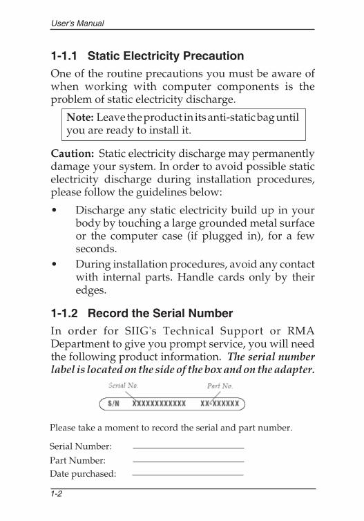
1-1.2 Record the Serial NumberIn order for SIIG's Technical Support or RMADepartment to give you prompt service, you will needthe following product information. The serial numberlabel is located on the side of the box and on the adapter.
Please take a moment to record the serial and part number.
Serial Number:
Part Number:Date purchased:

Introduction
1-3
1-2 Introducing the USB Over IPThe USB Over IP allows network users to connect remoteUSB devices like, printers, scanners, digital cameras andUSB Flash drives over the network. It is ideal for homeoffice, small office or classroom use! User friendly clientsoftware, which maps USB devices connected to theUSB Over IP onto the local host computer, is included
1-2.1 Features and BenefitsUSB Connectivity• Supports various types of USB devices• Four high-speed USB ports• Compatible with bulk, interrupt and isochronous
USB devices
Network Connectivity• Supports Ethernet networks• RJ45 LAN connectors• 10/100 auto sensing• Supports Static or DHCP IP addressing
Client Software• Supports various types of USB Traffic (Control,
Bulk, Interrupt and Isochronous)• Designed to comply with Microsoft WHQL
Unclassified software category tests• Support both Ethernet and Wi-Fi networks• User-friendly application interface• Device mapping feature for adding and removing
USB devices• Printer auto connect feature

1-4
User's Manual
1-2.2 System Requirements• Windows® XP (32-/64-bit)/Server 2003 (32-/64-
bit)/Vista (32-bit)• Ethernet network with an available RJ45 port• CD-ROM drive
1-2.3 Layout
• Power LED: USB Over IP is powered on• Ready LED: when the box is first powered on, the
USB Over IP goes through it's initialization/bootupsequence. The LED will blink for 10 seconds, thenit will go off for 10-15 seconds, initialization issuccessful when the LED comes back on. If theReady LED ever goes off, power-off then power-onthe USB Over IP. It is recommended to unplug alldevices from the USB Over IP during it'sinitialization/bootup sequence.
Power LEDReady LED
Ethernet Port Power Adapter JackUSB Ports
USB IP Admin Software Utility
2-1
Chapter 2Hardware Installation andDevice Compatibility
2-1 Hardware InstallationGeneral hardware installation instructions are providedbelow. Since the design of computer cases andmotherboards vary, refer to your computer's referencemanual for further information, if needed.Static Electricity Discharge may permanently damageyour system. Discharge any static electricity build up inyour body by touching your computer case for a fewseconds.
1. Connect one end of your Ethernet cable to theEthernet Port of the USB Over IP.
2. Connect the other end of the Ethernet cable to anavailable RJ45 port on your Ethernet switch or hub.
3. Plug the power adapter into the USB Over IP, thenplug the power adapter into a reliable power source.
4. Wait for the USB Over IP to complete it'sinitialization/bootup sequence and the Ready LEDto light up before proceeding to the next section.
2-2 Device ConnectionThe USB Over IP supports up to four USB devices.Connect your USB device(s) to any port on the USB OverIP. The green LED will light to show successfulconnection.

User's Manual
2-2
2-3 USB Device SupportUSB Over IP Admin client software is based on openarchitecture, wherein the USB Over IP box virtualizesthe connected USB devices onto the remote client. TheClient, installed on the remote host, interacts with theUSB Over IP box and enables remote access. In thisapproach, device drivers of the connected USB deviceare installed on the remote host only, as if the device isconnected to it's USB ports.
2-3.1 USB Device Interoperability ListThe following USB devices were tested in Windows XPSP2 32-bit operating system in default setup mode.
Device Type Make Model
Serial and Parallel
Prolific PL2303
FTDI USB to 4-port Serial
MCS7840 USB to 4-port Serial
MCS7820 USB to 2-port Serial
MCS7720 USB to 2-port Serial
Networking MCS7830 USB to 10/100 Adapter
Hubs
BelkinHub
Hub
D-Link Hub
i-Rocks Hub
Enter Hub
PhoneSkype USB Audio Device
YAP USB Audio Device
TV Tuner DiamondMultimedia PVR660
Wireless Belkin USB to 802.11G

USB IP Admin Software Utility
2-3
2-3.1 Device Interoperability List Contd.Device Type Make Model
Webcam
Logitech Quickcam Messenger
Logitech Quickcam Easy
Logitech Quickcam Go
Logitech Quickcam Pro 3000
Logitech Quickcam Pro 4000
Logitech Quick Communicate STX
Microsoft LifeCam VX-1000
Microsoft LifeCam VX-3000
Creative Vista Plus Webcam
Quantum QHMPL 500lm-8lm
Frontech e-CAM
Microsoft LifeCam VX-6000
Logitech Quickcam for Notebooks Pro
Speakers
Sony Sony USB Speakers
MicrosoftMicrosoft Life Chat LX3000 headphones
Turtle Beach Audio Advantage Micro Sound Card
Multimedia SIIGUSB SoundWave 7.1
USB SoundWave 7.1 Pro

User's Manual
2-4
2-3.1 Device Interoperability List Contd.
Device Type Make Model
Keyboard
Acer Acer Keyboard
Apple Mac Mac Extended Keyboard
Microsoft Comfort curve keyboard
Microsoft Intranet Pro Keyboard
Mouse
Apple Apple Optical mouse
Apple Apple mouse
Microsoft Microsoft Basic mouse
Logitech Logitech mouse
Sun Sun mouse
Dell Dell mouse
IBM IBM mouse
Joystick Microsoft Joystick
Mass StorageDevice
Iomega USB Zip 100
Toshiba Transmemory
Kingston DataTraveler DTI 1GB
Kingston DataTraveler MiniFunDTMFP/2GB
SanDisk Cruzer Micro 1GB
SuperTalent Super Flash Drive 2GB
Western DigitalHDD Enclosure
WD600 U017 - 60GB Go
ViPower Pocket Drive VP-2528
Transcend 2GB JF V30
ZipSys USB to IDE controller
DVD NEC DVD ROM

USB IP Admin Software Utility
2-5
2-3.1 Device Interoperability List Contd.
Device Type Make Model
Printers
HP
Business InkJet 1200
DeskJet D2360
LaserJet 1020(GDI printer)
DeskJet 3740
PhotoSmart 3200
LaserJet 2200d
Epson
EPL-6200L
Stylus C87 Plus
Stylus C58 Plus
LX-300 +II
Canon iP1700
Samsung ML 1210
WeP Bloom Laser 1600+
Multi-functionprinters
HP
OfficeJet 4315 All-in-One
DeskJet F380 All-in-One
LaserJet 3200
PhotoSmart C6188All-in-One
PhotoSmart C3100All-in-One
Canon MP160 MFP
Brother MFC-9700 Multi Function
Dell All-in-One Printer 946
Scanners HPScanJet 1300C
ScanJet 4470C

Driver Installation
3-1
Chapter 3Driver Installation
3-1 Driver InstallationThis section provides information on how to install theUSB Over IP drivers.
3-1.1 Windows XP1. Connect the USB Over IP to your network and boot
up Windows.2. At the Windows desktop insert the driver CD.3. Autorun should start the installation, if not, click
Start, then Run. Type D:\Launch.exe then clickOK. (Change D: to match your CD-ROM driveletter)
4. At the USB Over IP screen click Install.

User's Manual
3-2
5. At Choose Components, click Next.
6. At Choose Installation Location, click Install.

Driver Installation
3-3
7. At the Security Alert, click Yes. (skip this step for32-bit XP)
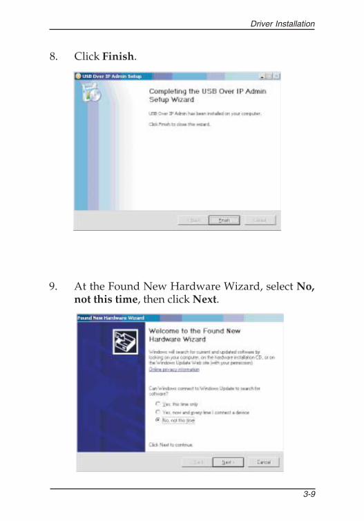
8. At Completed, click Finish.

User's Manual
3-4
9. At the Found New Hardware Wizard, select No,not this time, click Next. (skip this step if notprompted)
10. Windows detects a new device, at the Found NewHardware Wizard, select Install the softwareautomatically (Recommended), click Next.

Driver Installation
3-5
11. At the Security Alert, click Yes. (skip this step for32-bit XP)
12. Click Finish.

User's Manual
3-6
13. At Windows Security Alert, click Unblock. (skipthis step for 32-bit XP)
14. Repeat steps 9-12 for each USB Over IP connectedto your network.
15. Restart XP to complete the installation.
3-1.2 Windows Server 20031. Connect the USB Over IP to your network and boot
up Windows.2. At the Windows desktop insert the driver CD.3. Autorun should start the installation, if not, click
Start, then Run. Type D:\Launch.exe then clickOK. (Change D: to match your CD-ROM driveletter)
Driver Installation
3-7
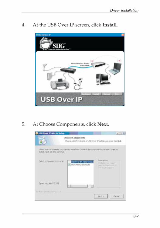
4. At the USB Over IP screen, click Install.
5. At Choose Components, click Next.

User's Manual
3-8
6. At Choose Install Location, click Install.
7. At Security Alert, click Yes.
Driver Installation
3-9
8. Click Finish.
9. At the Found New Hardware Wizard, select No,not this time, then click Next.

User's Manual
3-10
10. Select Install the software automatically(Recommended), click Next.
11. At Security Alert, click Yes.

Driver Installation
3-11
12. Click Finish.
13. Repeat steps 9-12 for each USB Over IP connectedto your network.
3-1.3 Windows Vista™1. Connect the USB Over IP to your network and boot
up Windows.2. At the Windows desktop insert the driver CD.
At the Auto Play window: click Open folder to viewfiles.

User's Manual
3-12
If Auto Play doesn't start: click Start, in the StartSearch box, type D:\Launch.exe. (Change D: tomatch your CD-ROM drive letter)
3. Right click Launch, click Run as administrator.Click Allow.
4. At the USB Over IP screen, click Install.

Driver Installation
3-13
5. At Choose Components, click Next.
6. At Choose Install Location, click Install.

User's Manual
3-14
7. At Windows Security, click Install this driversoftware anyway two times.
8. Click Finish.

Driver Installation
3-15
10. Right click the USB Over IP Admin icon located onthe desktop, click Properties.
9. At Windows FireWall Security Alert, click Unblock.

User's Manual
3-16
11. Click Compatibility tab. Check Run this programas an administrator, click OK. (This step may takeup to 30 seconds to complete)
12. Click Start, All Programs, USB Over IP.

Driver Installation
3-17
13. Right click the USB Over IP Admin icon, clickProperties.
14. Click Compatibility tab, check Run this programas an administrator, click OK.

User's Manual
3-18
3-2 To Verify Installation
3-2.1 Windows XP/Server 20031. Right click My Computer, click Manage, click
Device Manager.2. Double click USBoIP Device Servers.3. Virtual USB Bus should be displayed for each USB
Over IP connected to the network.
3-2.2 Windows Vista1. Right click Computer, click Manage, click
Continue.2. Click Device Manager, double click USBoIP Device
Servers.3. Virtual USB Bus should be displayed for each USB
Over IP connected to the network.

Driver Installation
3-19
3-3 Set IP AddressThe factory default IP address given to the USB Over IPis 192.168.3.22. This address may not match yournetwork's subnet address, in this case, your USB deviceswill not be detected by the USB Over IP Admin. Thissection guides you through setting the IP address tomatch the subnet mask of your network.
1. At the SIIG USB Over IP screen, click Configure.
Note: You must have Administrator rights to runthis utility in Windows Vista.

User's Manual
3-20
2. Click Unblock. (Skip this step if not prompted)
3. At List of Servers, double click the MAC address ofthe USB Over IP you want to change.

Driver Installation
3-21
4. At IP Configuration screen, either type in the IPaddress, subnet mask, and gateway or select DHCP,then click Change.
5. Click Exit to save and exit.

Configuration Utility
4-1
Chapter 4USB Over IP Admin
4-1 Introducing the USB Over IP AdminThe USB Over IP Admin is a user friendly PC softwarewhich supports High speed USB cameras, USB audio,USB Printers, Multi-function printers, scanners, storagedevices, PDAs, digital cameras, serial adapters, mice,keyboards and much much more.
• Supports various types of USB Devices (class,multifunction and vendor specific)
• Supports all types of USB traffic (control, bulk,interrupt and isochronous)
• Designed to comply with Microsoft WHQLUnclassified software category tests
• Server Manager with search and display serverson network
• Supports both Ethernet and Wi-Fi networks• Supports USB device safe removal• User friendly application interface• Device mapping feature for adding and removing
USB devices• Printer auto connect feature

User's Manual
4-2
4-2 Windows Vista FireWallWindows Vista operating system firewall blocks theUSB Over IP Admin Quick Start Icon from starting upautomatically at boot up. Follow the steps below toenable it.
1. After Windows Vista has fully started, click on theBlocked startup programs icon located in thetaskbar by the system clock.
2. Place the mouse cursor over Run blocked program,then click USB Over IP Admin Application. ClickAllow.
Note: Follow these steps each time Windows Vistais booted up or restarted.

Configuration Utility
4-3
4-3 Using the USB Over IP AdminThe USB over IP Admin is used to connect to your USBdevices and configure your USB Over IP server.
4-3.1 Quick Start IconThe USB Over IP Admin Quick Start Icon installsautomatically during driver installation and is locatedon the right side of the taskbar by the system clock.Double click the icon to open the USB Over IP Admin.
4-3.2 USB DevicesThe USB Devices window is divided into two sections,Device Mapping and Device Details. Device Mappingshows all detected USB devices, Device Details showsinformation about the USB device.
User's Manual
4-4
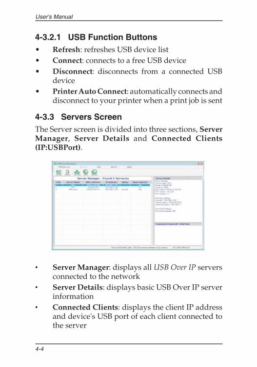
4-3.2.1 USB Function Buttons• Refresh: refreshes USB device list• Connect: connects to a free USB device• Disconnect: disconnects from a connected USB
device• Printer Auto Connect: automatically connects and
disconnect to your printer when a print job is sent
4-3.3 Servers ScreenThe Server screen is divided into three sections, ServerManager, Server Details and Connected Clients(IP:USBPort).
• Server Manager: displays all USB Over IP serversconnected to the network
• Server Details: displays basic USB Over IP serverinformation
• Connected Clients: displays the client IP addressand device's USB port of each client connected tothe server

Configuration Utility
4-5
4-3.3.1 Server Function Buttons• Refresh: searches for servers• Unlock: unlocks password enabled servers• Upgrade: upgrades server firmware• Setup: enters Server Configuration. This button is
disabled whenever a server is password enabled• Restore: restores the box to its factory default IP
settings of 192.168.3.22

User's Manual
4-6
4-4 How To's
4-4.1 Device Mapping4-4.1.1 How to Connect
1. In the Device Mapping window, select a devicewho's status is Free, then click the Connect button.
2. The Status will change to Connected.
3. Depending on the device, Windows will eitherautomatically install a driver for it or prompt youfor a driver. Read the device's user's manual fordriver installation instructions, if needed.

Configuration Utility
4-7
4-4.1.2 How to Disconnect1. In the Device Mapping window, select a device
who's status is Connected, then click the Disconnectbutton.
2. The Status will change to Unloading then to Free.
User's Manual
4-8
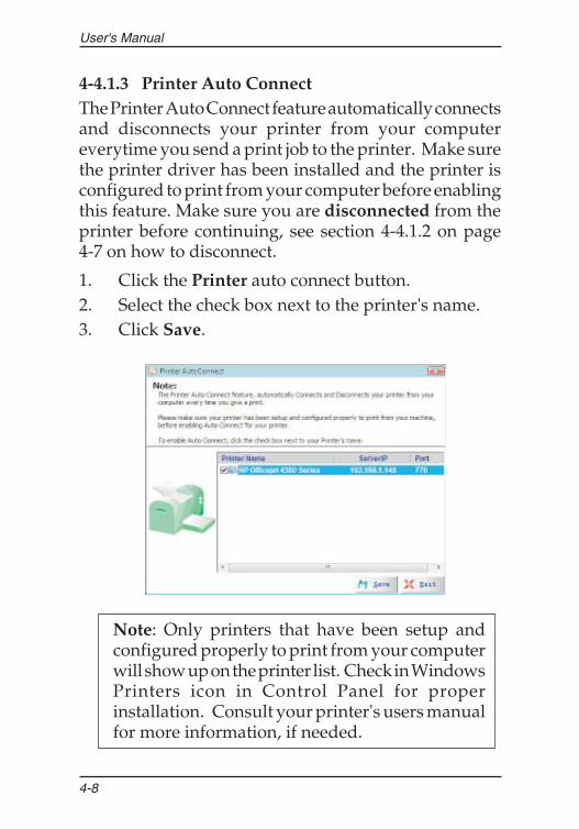
4-4.1.3 Printer Auto ConnectThe Printer Auto Connect feature automatically connectsand disconnects your printer from your computereverytime you send a print job to the printer. Make surethe printer driver has been installed and the printer isconfigured to print from your computer before enablingthis feature. Make sure you are disconnected from theprinter before continuing, see section 4-4.1.2 on page4-7 on how to disconnect.
1. Click the Printer auto connect button.2. Select the check box next to the printer's name.3. Click Save.
Note: Only printers that have been setup andconfigured properly to print from your computerwill show up on the printer list. Check in WindowsPrinters icon in Control Panel for properinstallation. Consult your printer's users manualfor more information, if needed.

Configuration Utility
4-9
4-4.2 Server Manager4-4.2.1 Setup (Server Configuration)Use the Setup button to change server name, modify IPsettings and enable or disable password. If the server ispassword protected the setup button will be disabled.To enable the Setup button, go to section 4-4.2.2 UnlockServer and Reset Password.
1. In Server Manager, click the server that you want toconfigure.
2. Click the Setup button.
3. Select Basic Settings tab, modify the server name.

User's Manual
4-10
4. Select IP Settings tab. Check Modify, then eitherselect Static and type in your IP address andgateway or, to have your server configuredautomatically, select DHCP.
5. Select Password tab. Check Modify, then enable,disable or change your password.
6. Click Save to save your changes and exit.

Configuration Utility
4-11
4-4.2.2 Unlock Server and Reset the PasswordWhenever the USB Over IP is password protected, it'sStatus will be Locked. Follow the steps in the order thatthey appear to unlock the server.
1. Select the locked server and click the Unlock button.
2. Type in your current password, and click OK.

User's Manual
4-12
3. Your password will be confirmed or denied, clickOK. If failed, try again. If you continue to haveproblems, check with your system administratorfor the correct password.
4. Click Refresh button, the server status should beUnlocked. Click the Setup button.

Configuration Utility
4-13
5. Select the Password tab.
6. Check Modify, uncheck Enable Password, thenclick Save.

User's Manual
4-14
4-4.2.3 Refresh (Refresh Servers)
1. Click the Refresh button.
2. The Searching for Servers box will pop up.
Configuration Utility
4-15
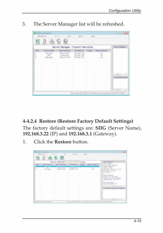
3. The Server Manager list will be refreshed.
4-4.2.4 Restore (Restore Factory Default Settings)The factory default settings are: SIIG (Server Name),192.168.3.22 (IP) and 192.168.3.1 (Gateway).
1. Click the Restore button.

User's Manual
4-16
2. Click OK.
3. Click OK.
4. Click Refresh to display the server list.

Configuration Utility
4-17
4-4.2.5 Upgrade (Upgrade Firmware)
1. Select a server, click the Upgrade button.
2. In Select File box, browse to or type in the locationof the file, then click Transfer. Do not unplug thepower adapter from the USB Over IP during theupdate process.

User's Manual
4-18
4-4.2.6 Configure IP Address: Server Not On the SameSubnet
1. At the Server Manger screen, select the server thatis not on the same subnet.
2. At Configure IP Address, click Yes.

Configuration Utility
4-19
3. Click Unblock. (Skip this step if not prompted)
4. Either type in an IP address and Gateway or selectDHCP, then click Change.

User's Manual
4-20
5. At the Server Manager screen, click Refresh. Yesshould be displayed in the Same Subnet? column ofthe server.

5-1
Technical Support & Product Return
5-1 OverviewThis chapter will give you instructions on how to obtainproduct information, contact technical support andreturn defective product. This user's manual is writtenwith easy-to-understand instructions on how toconfigure and install this product in your system. Weencourage you to consult this manual as your first stepfor technical assistance.There are several steps you can take should you findproblems with this product. It is most helpful if youconsult the following resources:
1. Installation instructions from this user's manual2. Technical Support3. Warranty & RMA Information
Chapter 5Technical Support& RMA

5-2
User's Manual
5-2 Technical Support and WarrantyQUESTIONS? SIIG’s Online Support has answers! Simply visitour web site at www.siig.com and click Support. Our onlinesupport database is updated daily with new drivers and solutions.Answers to your questions could be just a few clicks away. You canalso submit questions online and a technical support analysts willpromptly respond.
SIIG offers a lifetime manufacturer warranty with this product.Please see our web site for more warranty details. If you encounterany problems with this product, please follow the proceduresbelow.
A) If it is within the store's return policy period, please return theproduct to the store where you purchased from.
B) If your purchase has passed the store's return policy period,please follow these steps to have the product repaired or replaced.
Step 1: Submit your RMA request.Go to www.siig.com, click Support, then RMA to submit arequest to SIIG RMA. If the product is determined to bedefective, an RMA number will be issued. SIIG RMA departmentcan also be reached at (510) 413-5333.Step 2: After obtaining an RMA number, ship the product.• Properly pack the product for shipping. All software, cable(s)
and any other accessories that came with the original packagemust be included.
• Clearly write your RMA number on the top of the returnedpackage. SIIG will refuse to accept any shipping package, andwill not be responsible for a product returned without anRMA number posted on the outside of the shipping carton.
• You are responsible for the cost of shipping. Ship the productto the following address:SIIG, Inc.6078 Stewart AvenueFremont, CA 94538-3152, USARMA #:
• SIIG will ship the repaired or replaced product via Groundin the U.S. and International Economy outside of the U.S. atno cost to the customer.

5-3
Technical Support & Product Return
Blank Page

5-4
User's Manual
Blank Page

03-0315A


![Application Procedures for Registration of Product ...€¦ · Application Procedures for Registration of Product Certification [Chronicle of Promulgation and Amendments] Adopted](https://static.fdocuments.net/doc/165x107/5eaa372eac648854e34375d1/application-procedures-for-registration-of-product-application-procedures-for.jpg)


