Signals - الاتحاد الطلابي :...
29
2/3/2012 1 LECTURE 3 PART1 Signals • Some signals’ proprieties •Scientific notation and dealing with big number 2.7 Propagation delay The time taken for a signal to travel from its source to its destination is known as propagation delay. This is derived from the verb ‘propagate’ which in a physics context means ‘spread’ or ‘travel’.... Imagine you are driving a car then your delay will depend on what? speed distance managements
Transcript of Signals - الاتحاد الطلابي :...

2/3/2012
1
LECTURE 3 PART1
Signals
• Some signals’ proprieties•Scientific notation and dealing with big number
2.7 Propagation delay
� The time taken for a signal to travel from its source to its destination is known as propagation delay. This is derived from the verb ‘propagate’ which in a physics context means ‘spread’ or ‘travel’....
� Imagine you are driving a car then your delay will depend on what?
speeddistancemanagements
2/3/2012
2
2.7 Propagation delay
� The propagation delay depends on a number of factors:
1. The distance the signal has to travel
2. The signal’s speed.
3. Signals can also be delayed by the processes required to manipulate and manage them on their journey from sender to receiver
� Contemporary physics states that nothing can travel faster than the speed of light (or any electromagnetic wave) in a vacuum which, to the nearest meter, is 299 792 458 meters per second.
� You are more likely to see the speed of light given as ‘approximately 3 x 10⁸ m/s’ (that is 300 000 000 meters per second).
� Not all carriers are able to achieve the speed of light. A voltage pulse traveling in a copper cable has a speed of approximately 2 x 10⁸ m/s.
� It is often acceptable to round the numbers up or down to make calculation simpler (see next slide)
2.7 Propagation delay

2/3/2012
3
2.8 Attenuation and distortion
� As a signal travels from one device to another it has two problems to overcome:
1. The first is that it gets weaker the further it travels, because some of its energy is absorbed by the transmission medium�Attenuation
� Solution: An amplifier can be used to boost the signal power at the transmitter and receiver, and if necessary at various points in the transmission link, so that signal power can be maintained at a usable level.
2.8 Attenuation and distortion
2. Distortion: the signal can become distorted by external influences as it travels along the communication path.
A. other signals traveling in the vicinityB. by waves of energy such as solar energy, lightning, and pulses of energy
from electrical machinery� Examples from everyday life on distortion:
� Power on a TV and when use hairdryer nearby you can see spots and lines on the TV screen that are caused by the electromagnetic energy generated by the motor in the hairdryer.
� Place a mobile phone next to a radio you will often hear ‘beeps’ on the radio as the phone sends signals to the phone network.
� Unless distortion can be removed from the signal at the receiving end then Any amplification to overcome the problems of attenuation will also amplify any distortion in the received signal.
� Binary signals are quite resistant to distortion because they represent only two states that can usually be distinguished quite easily from any unwanted effects.
2/3/2012
4
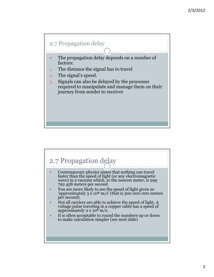
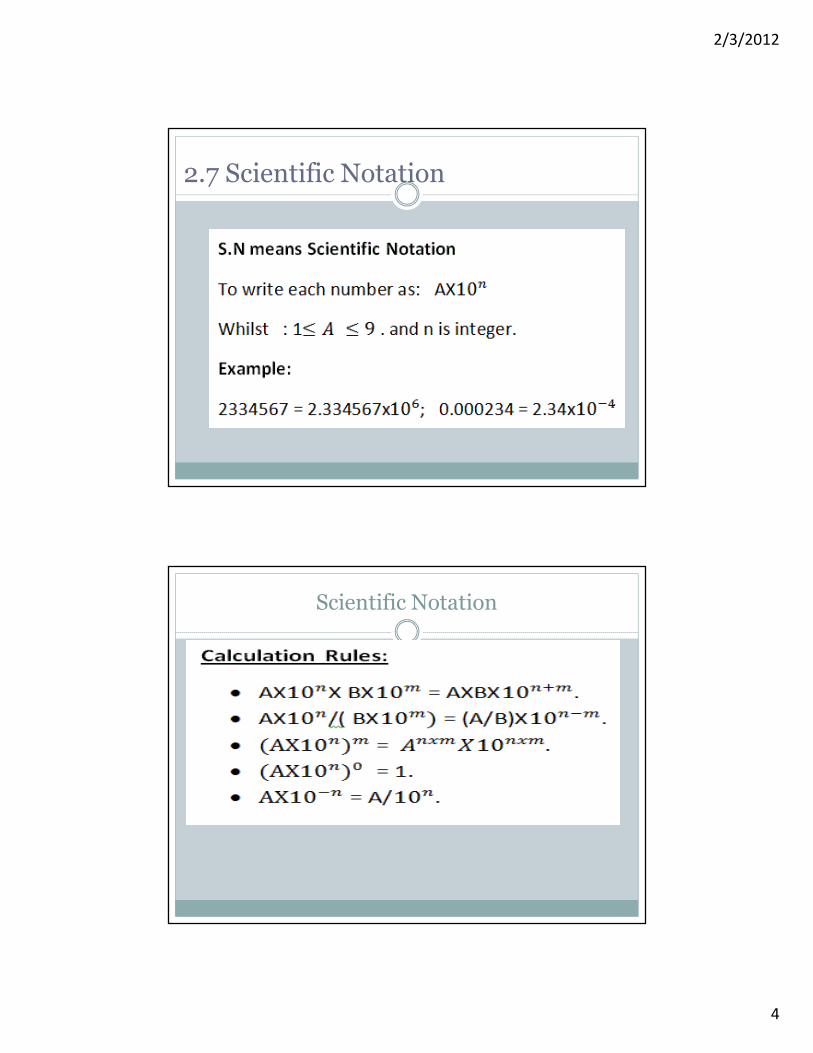
2.7 Scientific Notation
Scientific Notation

2/3/2012
5
� the longer the number, the less significant the right-most digit becomes.
� The digits at the left-hand end that are significant.� the degree of accuracy required by choosing how many left-hand digits we consider to be significant for our purposes. We call these significant figures. Then we round the original number up or down until all but the required significant figures are shown as 0s.
2.7 Rounding
Examples: � round 3482 to 3 significant figures � 3480 (we chose to round down since 3482 is closer to 3480 than 3490)
� round 3482 to 2 significant figures � 3500 (we chose to round up since 3482 is closer to 3500 than 3400)
� round 2.14565879 x 10⁸ to 4 significant figures � 2.146 x 10⁸� round 2.14565879 x10⁸ to 3 significant figures � 2.15 x 10⁸� round 299 792 458 m/s to 4 significant figures � 299 800 000
� round 299 792 458 m/s to 3 significant figures � 300 000 000
2.7 Rounding

2/3/2012
6
Wired Network
Lecture 3 Part 2
3 Wired networks
� This section starts by broadly classifying different types of network, first by the nature of the communication links used to connect devices and then by a network's geographical spread.
� Wired network configuration.
� LANs and Ethernet.
� Routers
� Magnitude comparisons
2/3/2012
7
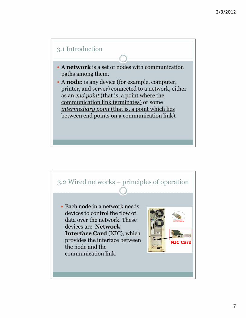
3.1 Introduction
� A network is a set of nodes with communication paths among them.
� A node: is any device (for example, computer, printer, and server) connected to a network, either as an end point (that is, a point where the communication link terminates) or some intermediary point (that is, a point which lies between end points on a communication link).
3.2 Wired networks – principles of operation
� Each node in a network needs devices to control the flow of data over the network. These devices are Network Interface Card (NIC), which provides the interface between the node and the communication link.

2/3/2012
8
3.2 Wired networks – principles of operation
� Media Access Control (MAC) address: Each node is assigned an identity number ( by the manufacturer) known as a MAC ( Media Access Control) address to distinguish it from all the other nodes on the network. It is used by other nodes when they want to send data to a particular destination.
� Frames: Messages between nodes are broken up into small chunks called packets, number of packets are placed together in one frame,( frame is like a bus which collect many passengers) which are sent one at a time.� Each frame includes some information which enables it to be routed
through the network and delivered to the intended destination. � All frames include the MAC address of both the destination node and the
sending node. � In some networks, frames are not routed specifically to the destination
node but are sent to every node on the network. ( this is the broadcasting ),Each node picks out those frames where the destination address matches its own.
3.2 Wired networks – principles of operation
� Again problem of attenuation: signals representing data get weaker the further they travel. This is one of the factors that could limit the maximum length of a communication link in a LAN. This limitation is overcome by the use of repeaters.
� Repeater: increases the practical distance between nodes by regenerating the signal and passing it on.

2/3/2012
9
� Networks classification:A) According to communication links nature:
1. Wired Network: networks that use a physical communication link such as cable – for example, copper or fiber-optic cable.
2. Wireless network: no physical connections between the nodes.
B) According to Geographical spread:1. Personal Area Networks (PANs): cover small areas such as a home, a single
room within a home or even a car. A PAN is a type of LAN. 2. Local Area Networks (LANs): connect together a number of nodes within a single
building or group of buildings situated close to each other. A LAN can connect together as few as 2 or 3 nodes or hundreds of nodes.
3. Wide Area Networks (WANs) connect together two or more LANs that are geographically separated. A WAN could include the LANs in offices of a national company and could even cross international boundaries.
C) According to shape or different node arrangements (topologies)
3.3 Networks classification:
3.3 Wired network configurations (topologies)
� Network nodes can be connected together in different arrangements known as topologies. We are going to describe four common topologies that you may come across

2/3/2012
10
3.3 Wired network configurations (topologies)
1. Bus topology: all the nodes connect to a single network cable and can communicate with every other attached node by placing a message onto the cable.
� How it works?� Each node connects to the same cable, so a frame sent by one
node will arrive at every other node. � Each node must read the destination MAC address in the frame
to decide whether or not to accept it.
� If any node becomes inoperable, all the other nodes are still able to communicate with each other,
–ve: Any cable failure will result in the loss of communication between nodes on opposite sides of the failure point.
3.3 Wired network configurations (topologies)
� Extended star topology: hubs are joined together so that nodes connected to one hub can communicate with nodes connected to another hub.
2/3/2012
11
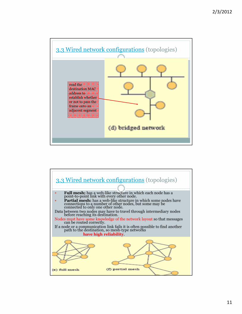
read the destination MAC address to establish whether or not to pass the frame onto an adjacent segment
3.3 Wired network configurations (topologies)
3.3 Wired network configurations (topologies)
� Full mesh: has a web-like structure in which each node has a point-to-point link with every other node.
� Partial mesh: has a web-like structure in which some nodes have connections to a number of other nodes, but some may be connected to only one other node.
Data between two nodes may have to travel through intermediary nodes before reaching its destination.
Nodes must have some knowledge of the network layout so that messages can be routed correctly.
If a node or a communication link fails it is often possible to find another path to the destination, so mesh-type networks
have high reliability.

2/3/2012
12
3.3 Wired network problems
� Problem: in some network topologies, only one node at a time is allowed to place a frame onto the network. This means that every node has to compete with every other node for access to the network. As a network grows and traffic increases, a point is reached where competition becomes so great that the network becomes unacceptably slow.
� Solution: Segmentation� A segment is a discrete portion of a network in which all nodes share
the communication link.� A switch or bridge : are devices used to join segments together. � Switches and bridges will examine each frame as it arrives and read
the destination MAC address to establish whether or not to pass the frame onto an adjacent segment.
� A segment will receive only frames destined for nodes within it or frames that need to be routed through it to reach other segments further along the network.
� In some networks each segment could contain just a single node
3.4 Routers
� A router: One type of network device which generally works at the edge of a LAN rather than within it.
� A router holds information about the structure of a network� A router can make decisions about how data should be routed through it.
� A router used to� Connect together different types of LAN, for example used to join an Ethernet LAN with a LAN that uses different protocols
� Connect different types of network. For example a router would be used to connect a LAN to a WAN

2/3/2012
13
3.5 protocols & standards
� Protocols – rules to govern how information is sent, transmitted and received.
� A number of organizations have taken responsibility for ensuring that particular communication protocols are clearly stated, recorded and made available to others.
� These organizations agree on and produce the necessary standards, which are a kind of technical specification that sets out the rules and requirements to ensure interoperability.
3.5 Establishing Ethernet standard
� A standards document is drawn up with the involvement and agreement of all interested parties, for example representatives of users, manufacturers and government agencies.
� The dominant standard in wired LANs is one that is commonly known as Ethernet.
� Establishing Ethernet standards� When: The first Ethernet network was developed in the early 1970,
long before the World Wide Web and personal computers (PCs). � Where: Ethernet was designed by researchers at the Xerox Palo Alto
Research Centre in California, USA to connect the Center's ‘Alto’ computers to an office printer.
� Why succeeded: One of the main reasons for its success lies with the decision to publish the standard (used open standards)

2/3/2012
14
� Open standards: are published and available to everyone.
� Availability of Open Standards helps to establish related products in the marketplace:
� Many different manufacturers are able to produce products that are compatible.
� This increases competition and drives down the costs to consumers.
� It increases manufacturers’ confidence in the market and so encourages them to invest in and develop products.
� This in turn is likely to lead to greater reliability.
3.5 Establishing Ethernet standard
� The standardizing body for Ethernet: the IEEE.� The Institute of Electrical and Electronics Engineers (IEEE):� The IEEE was formed from two earlier organizations: the American
Institute of Electrical Engineers (AIEE) and the Institute of Radio Engineers (IRE). As technology developed, the boundaries between these two organizations became more and more blurred and eventually, in 1963, they merged. The IEEE is based in the USA but is essentially a global association of professionals working in technical areas such as computing, telecommunications, power engineering and electronics
� How standards are developed:� The IEEE to establish a committee of interested bodies. � This committee forms a working group to collaborate and agree on the
details of the proposed standard. � The working group set up to standardize network technologies took its
name from the month and year (February 1980) of its formation, and became known as the ‘802 working group’.
� Task forces appointed to work on particular aspects of networking are each identified by a further number. The Ethernet taskforce and Ethernet standards are all identified by IEEE 802.3.
3.5 Establishing Ethernet standard
2/3/2012
15
Magnitude and estimates:
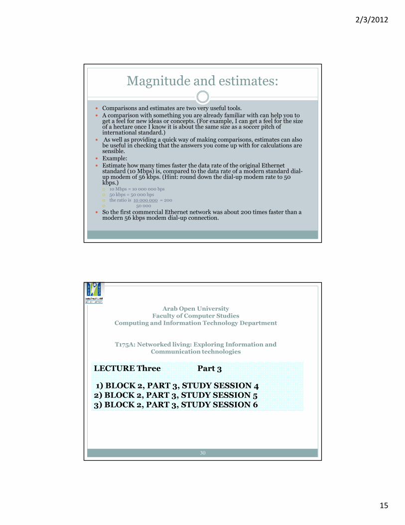
� Comparisons and estimates are two very useful tools. � A comparison with something you are already familiar with can help you to
get a feel for new ideas or concepts. (For example, I can get a feel for the size of a hectare once I know it is about the same size as a soccer pitch of international standard.)
� As well as providing a quick way of making comparisons, estimates can also be useful in checking that the answers you come up with for calculations are sensible.
� Example:� Estimate how many times faster the data rate of the original Ethernet
standard (10 Mbps) is, compared to the data rate of a modern standard dial-up modem of 56 kbps. (Hint: round down the dial-up modem rate to 50 kbps.)� 10 Mbps = 10 000 000 bps� 50 kbps = 50 000 bps� the ratio is 10 000 000 = 200� 50 000
� So the first commercial Ethernet network was about 200 times faster than a modern 56 kbps modem dial-up connection.
30
Arab Open UniversityFaculty of Computer Studies
Computing and Information Technology Department
T175A: Networked living: Exploring Information and Communication technologies
LECTURE Three Part 3
1) BLOCK 2, PART 3, STUDY SESSION 42) BLOCK 2, PART 3, STUDY SESSION 53) BLOCK 2, PART 3, STUDY SESSION 6
2/3/2012
16
4 Wireless networks31
� Main Points:
� How wireless transmissions take place?
� the principles of wireless transmission
� Wireless standards – WiFi and Bluetooth: � network structure
� how stations find each other in a network
� sharing the medium
� Data rate
� throughput
� operating range
� number of stations
4 Wireless networks32
• The focus of Section 3 was on LANs that use some kind of physical medium (for example, copper wires or fibre-optic cables) to connect together network nodes. In this section we'll be examining wireless...

2/3/2012
17
4.1 Introduction:33
� Wireless networks –, networks that transmit data through the air (or space) using radio waves.
� The principles of transmitting information using radio waves were discovered over a century ago.
� Using radio waves to provide the transmission links in a network is a relatively new and fast-growing technology.
� It enables us to connect into networks in public places like airports and city centers without needing a wired link.
4.2 Basic principles of wireless transmission34
� Aerial / Antenna: a special electrical conductor that picks up the radio signals. It can be used to both 1) receive and 2) send radio signals :
� “antennas convert electromagnetic waves into electrical currents and vice versa” From Wikipedia, the free encyclopedia
� 1) Receive:A) Radio signals arrive through the air as fluctuations in the (تقلبات)electromagnetic field of a radio wave. B) This induces (يستحث) a fluctuating electrical current to flow in the antenna. C) These fluctuations are detected and translated into data.
� 2) Send: Fluctuations in electrical current flowing in an antenna can also emit ( يبعث( a radio signal,
� Most devices operating in radio networks are transceivers (they can both send and receive radio signals) and will use the same antenna when sending and receiving.

2/3/2012
18
4.2 Basic principles of wireless transmission35
4.2 Basic principles of wireless transmission36
� When signals are traveling in cables, they follow the path of the cable, even though this may twist and turn. For this reason, cables are described as ‘guided’ media.
� Radio signals are not guided in this way. � The electromagnetic waves carrying the
signal can propagate in all directions, and may spread out in a spherical pattern as shown in Figure 12.
� The wavefronts refers to all points on a wave that are equidistant from its source.
� In figure wave fronts are represented by the concentric circles in both figures.
� The circles become fainter with distance from the centre, representing the way the signal weakens.
side view From above
This Fig. shows the energy radiation
of a non-directional Antenna
2/3/2012
19
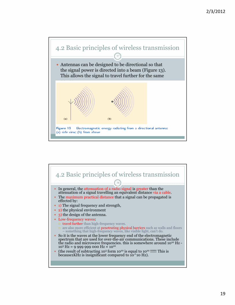
4.2 Basic principles of wireless transmission37
� Antennas can be designed to be directional so that the signal power is directed into a beam (Figure 13). This allows the signal to travel further for the same power.
4.2 Basic principles of wireless transmission38
� In general, the attenuation of a radio signal is greater than the attenuation of a signal travelling an equivalent distance via a cable.
� The maximum practical distance that a signal can be propagated is effected by:
� 1) The signal frequency and strength, � 2) the physical environment � 3) the design of the antenna. � Low-frequency waves:
� travel further than high-frequency waves. � are also more efficient at penetrating physical barriers such as walls and floors
– something that high-frequency waves, like visible light, can’t do.
� So it is the waves at the lower frequency end of the electromagnetic spectrum that are used for over-the-air communications. These include the radio and microwave frequencies. this is somewhere around 1010 Hz -103 Hz = 9 999 999 000 Hz ≈ 1010
� (the result of subtracting 103 form 1010 is equal to 1010 !!!!! This is because1KHz is insignificant compared to 10^10 Hz).

2/3/2012
20
4.3 Regulation 39
� Increasing demand for wireless technology means that the radio frequencies must be carefully managed and allocated by governments to satisfy all the different users and to prevent interferencebetween them.
� Before transmitting radio signals, organizations must usually obtain a license permitting them to use a specified frequency or band of frequencies.
40
� The industrial, scientific and medical (ISM)radio band : Band of radio frequencies which is available internationally for unlicensed users and lying between 2.4000 GHz and 2.4835 GHz . also referred to simply as the 2.4 GHz frequency band –(Some countries also allocate additional frequencies for unlicensed users.)
4.3 Regulation

2/3/2012
21
41
� Two wireless standards designed to operate within the ISM band of radio frequencies.
� WiFi, developed by the IEEE and covered by the IEEE 802.11 family of wireless LAN standards.
� Bluetooth, developed by the Bluetooth Special Interest Group (SIG) and covered by the IEEE 802.15 family of wireless PAN standards
4.3 Regulation
Study Session 4: Wireless communication42
Main Points:
� Wi-Fi communication technology
� Bluetooth communication technology

2/3/2012
22
4.4 WiFi43
� ‘Wireless Fidelity’ (WiFi): is used to connect devices together in one of two network configurations known as ‘ad hoc’ and ‘infrastructure’.
� In wireless LANs, nodes are referred to as stations –because each communicating device acts as a radio station with transmitter and receiver. These functions, and the necessary control functions, are provided by a wireless network interface card (wireless NIC) in a similar way to wired networks.
4.4WiFi Network Structure (operation modes)44
� 1) Ad hoc mod� ‘ad hoc’ means ‘for a specific purpose, impromptu, not pre-planned’.� In an ad hoc network, stations communicate with each other directly,
no intermediary or central control. � how it is established?� When one WiFi device comes within range of another, a direct
communication channel can be set up between them. This is known as peer-to-peer communication.
� Additional devices can join the network, all communicating with each other in a broadcast fashion. Here it means that a message sent by one node will arrive at every other node in the network, regardless of the destination address.
� An ad hoc network is independent of, and isolated from, any other network
� Where it can be used:� For ex. In a business meeting, sharing information between portable
devices (lap-top computers or personal digital assistants (PDAs))
2/3/2012
23
4.4 WiFi Network Structure (operation modes)
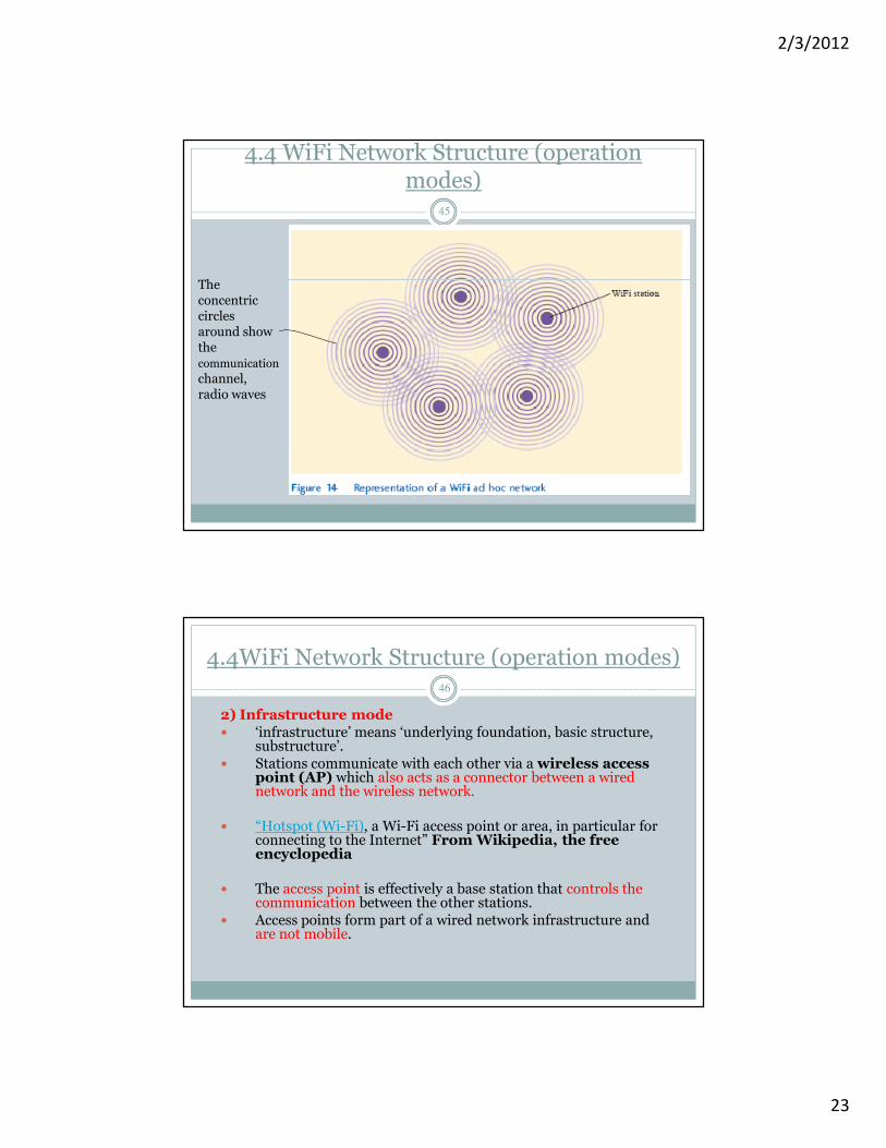
45
The concentric circles around show the communication
channel, radio waves
4.4WiFi Network Structure (operation modes)46
2) Infrastructure mode� ‘infrastructure’ means ‘underlying foundation, basic structure,
substructure’.� Stations communicate with each other via a wireless access
point (AP) which also acts as a connector between a wired network and the wireless network.
� “Hotspot (Wi-Fi), a Wi-Fi access point or area, in particular for connecting to the Internet” From Wikipedia, the free encyclopedia
� The access point is effectively a base station that controls the communication between the other stations.
� Access points form part of a wired network infrastructure and are not mobile.

2/3/2012
24
4.4 How WIFI stations find each other47
� A WiFi station determines whether it is in range of an AP by transmitting an enquiry, known as a probe request frame (a management frame – a type of frame that does not carry any message data. ), and waiting for a response.
� If more than one AP responds, the station will choose to communicate with the one that has the strongest signal.
� Just like the nodes on an Ethernet network, each station must have a means of being uniquely identified by a MAC address.
� Every frame in addition to the original data contain the MAC address of the source, destination and access point, as well as other management data that enables the frames to be correctly sequenced and errors to be detected.
48
� Sharing the medium
� All the stations in a WiFi network share the same communication channel � only one station at a time can send data.
� A station waits until it detects a period of inactivity and then uses a special protocol which prevents two or more stations sending data at exactly the same time.
� The exchanges involved in these protocols are another example of management data.
4.4 WiFi
2/3/2012
25
49
� Data rate� The first WiFi standard was developed in 1997. � At the time of writing, the latest WiFi standard to be published –
IEEE 802.11g – defines a data rate of 54 Mbps.� Rate for transmitting messages between stations is affected by:
1) The management information that is included with each frame.
2) the protocols used to enable multiple stations to share the communication channel;
� both points 1 & 2 impose an overhead that uses up some of the capacity of the communication channel � reduces the capacity available for sending message data (as compared to management data) -> effective data rate will be lower than the value quoted.3) Multiple users on a WiFi network.
� As the number of users increases, the data rate available to each individual user decreases.
4.4 WiFi
50
� throughput : The practical message data rate that can be achieved in a wireless network
� Even in ideal operating conditions, the throughput may be only 50% to 75% of the maximum data rate.
� For WiFi, throughput is generally about half the maximum data rate possible on the communication channel, giving about 30 Mbps for 802.11g networks, and this has to be shared between all the stations on the network
4.4 WiFi

2/3/2012
26
51
� Operating range is affected by:1) Distance from the AP (or in the case of an ad hoc network, with distance from other stations) � will reduce as the distance increases.
� Maximum data rates can be achieved only within about 30 m of an AP, tailing off at distances greater than this.
� For 802.11g networks the data rate drops to as low as 1 or 2 Mbps at 100 m.
2) Physical barriers such as partitions and walls will further reduce the maximum rate possible at a given distance from the AP.
4.4 WiFi
52
� Number of stations (no limit but in practical manufacture may put one to prevent congestion)
� The WiFi standards do not define any upper limit on the number of stations that can join a network.
� As the number of communicating stations increases, the channel capacity available for each station decreases.
� A point will eventually be reached when the network becomes too congested to provide an adequate service.
4.4 WiFi

2/3/2012
27
53
4.5 Bluetooth
� Why it was developed? ( the need for it)� to eliminate the need for connecting wires between local ICT devices such as keyboards, monitors, printers, PDAs (Personal Digital Assistants), cell phones and headsets.
� Infrared would solve the problem so why Bluetooth?
� Infrared require line-of-sight positioning while Bluetooth signals do not.
54
� The Bluetooth standard: (when developed and the parties involved)
� Is part of the IEEE 802.15 family of standards for wireless PANs. It was developed by a group of five interested parties who, in 1998, formed the Bluetooth Special Interest Group (SIG) and founded the Bluetooth consortium. Now the consortium has over 2,000 members.
� Frequency used: Like WiFi, Bluetooth uses the 2.4 GHz ISM frequency band.
� Microchip instead of wireless NIC: Bluetooth wireless transceiver and control functions are embedded in a small, low-cost microchip that is more suitable for incorporation into small devices, and has a much lower power requirement than a WiFi NIC.
4.5 Bluetooth

2/3/2012
28
55
� How devices found each other in a Bluetooth network?When switched on, Bluetooth devices find each other by transmitting a message which alerts other Bluetooth devices in the vicinity
� Bluetooth network structure: � Any two Bluetooth-enabled devices can form an ad hoc connection and establish a personal area network (PAN) known as a piconet
� One device in the piconet becomes the master unit and the others act as slaves, responding to ‘commands’ from the master.
� Piconet which can connect together up to eight communicating devices, each being identified by its MAC address.
4.5 Bluetooth
56
� Sharing the medium: The master unit controls all aspects of the communication within the piconet, designating dedicated time slots when each slave can communicate. This prevents slaves from sending data simultaneously.
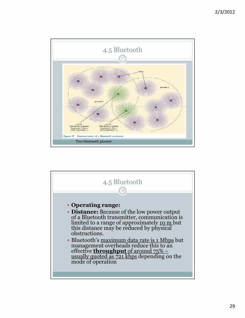
� Number of stations:� eight active devices forms a piconet� when need for more than eight active devices � two or more piconets can be connected together into what is known as a scatter net.
� In scatter net, every piconet must have one master, but a device could be a slave in one piconet and a master in another.
� Information can then be passed from piconet to piconet under the control of the piconets’ master units.
4.5 Bluetooth
2/3/2012
29
57
4.5 Bluetooth
Two bluetooth piconet
58
� Operating range:� Distance: Because of the low power output of a Bluetooth transmitter, communication is limited to a range of approximately 10 m but this distance may be reduced by physical obstructions.
� Bluetooth’s maximum data rate is 1 Mbps but management overheads reduce this to an effective throughput of around 75% –usually quoted as 721 kbps depending on the mode of operation
4.5 Bluetooth