Sigma δelta - Barry Rudolph:::Recording Engineering ... 5. Sigma δelta Operation 22 The Remote App...
44
Sigma δelta Remote-Controlled Analogue Mix Engine User Guide Sigma δelta. This is SSL. www.solidstatelogic.com
Transcript of Sigma δelta - Barry Rudolph:::Recording Engineering ... 5. Sigma δelta Operation 22 The Remote App...

Sigma δeltaRemote-Controlled Analogue Mix Engine
User Guide
Sigma δelta. This is SSL.
www.solidstatelogic.com
2
Table of Contents
1. Introduction 4About this User Guide 4Sigma δelta Overview 5
What is Sigma δelta and what was the idea behind it? 5How do I operate Sigma δelta? 5How does Sigma work? 6Setup Concepts 6Typical Sigma δelta Setup 7
2. Hardware Installation 8Installation Overview 8Front Panel 9Rear Panel 10CHIP (Channel inputs) and CHOP (Channel direct outputs) 11Miscellaneous Connections 11
3. Software Installation and Configuration 12Installing the Remote App 12Installing the δelta-Control Plug-in 13
iLok 13Installing ipMIDI Software 14Nucleus Remote Profile 14Sigma’s Internal Software 14
4. Network Setup 15General 15
Sigma’s IP Address 15Useful Built-In Features 15
Network Connection Examples 161. Fixed IP – Direct Connection 162. Router (and Switch) Connection using DHCP – Allows Access to Internet 183. Connection in a facility that has multiple SSL Consoles/Multiple ipMIDI devices 19
System Workflow tips 20Boot Order 20Channel Names 20δelta Plug-ins 20Sigma Delta Nucleus Profile 20SSL Console Transport Master 20Web Browser Interface 21Copying Sigma Settings from earlier software 21Translating Sigma v1.0.3.x Automation to the δelta System 21

3
5. Sigma δelta Operation 22The Remote App Interface 22MASTER 23
Master Meter 23Mix Bus Inserts 23Level Control 23B TO A Function 24USER Buttons 24MON/MONITORING Box 24H/P Box 25MIDI LEARN 25FOOTSWITCH 25DIM SETTINGS 25iJack Input 25
CHANNELS 26GLOBAL SETUP 27
SETTINGS 28SETUP Box 28NETWORK Box 30MISCELLANEOUS Box 30
SAVE and LOAD Buttons 32
6. Sigma δelta-Control Automation 33Overview 33The δelta-Control Advantage 33Workstation Setup - Pro Tools 33The δelta-Control GUI 34Workflow Setup 34Mixing with δelta-Control 35Using DAW Editing Tools 35
For Pro Tools, Cubase, Nuendo and Ableton Live 35Other DAWs 35
7. Automating Sigma’s Mix Busses 36Setup Instructions 36
Appendices 37Appendix A – Connectors & Pinouts 37Appendix B – Signal Flow Block Diagram 39Appendix C – Support 40
FAQs 40Required Software 41Sigma’s Internal Software 41Hardware 42
Appendix D – Specifications 43Technical & Environmental 43
Appendix E – Limited Warranty 43
1. Introduction
AboUT THIS USer GUIDeCongratulations on purchasing your Solid State Logic Sigma δelta. This User Guide will help you to install and configureyour Sigma δelta for your studio.
This User Guide is arranged into the following sections:
Introduction An overview of Sigma δelta’s features
Hardware Installation Provides information on Sigma δelta’s physical connections and how to connectthem to your existing studio equipment
Software Installation Lists all the software required to make Sigma δelta work with your DAW
Network Setup Guides you through configuring Sigma δelta to work on your computer network andtablet/smartphone
Connecting to and Using Sigma Details how to operate Sigma δelta and discusses control from the Remote app
δelta-Control Automation plug-in Explains how to use the δelta-Control plug-in to automate Sigma channel volumeand mutes
Appendices Contains additional documentation for reference
4
Document History82BMSM02A March 2016 Initial Release

Page 5
SIGmA δeLTA overvIew
what is Sigma δelta and what was the idea behind it?Sigma δelta consists of three independent elements – one hardware component and two software components – whichwhen combined, form the central hub of a hybrid music production studio.
The hardware is a 2U, remote-controllable analogue mix engine with 16 stereo/mono inputs and outputs, 2 mix buses (Aand B), mix bus insert points, comprehensive monitoring, a talkback input and customisable user buttons. The idea ofthe Sigma δelta mix engine was to bring the sound of an SSL console together with all the workflow advantages of mixingin a DAW. Sigma is built upon the same Superanalogue technology as our Duality and AWS consoles. Superanaloguecircuit design gives you extended frequency response, precise stereo imaging, clarity and depth. Sigma is designed forthe professional looking to add that extra 10% to their sound that even the best plug-in emulation cannot achieve.
The Sigma δelta mix engine features LED metering on all 16 channel strips and an additional high resolution stereo mastermeter. The blue rotary encoder is switchable (via a push function) between controlling the following levels: control roommonitor level, headphones, Mix Bus A and Mix Bus B master “fader” gains.
The Sigma δelta Remote app is a cross-platform app through which all the mix engine functions can be accessed. The appalso takes care of loading and saving settings, enabling remote control options, as well as updating the Sigma firmware.
The third element is the δelta-Control plug-in. Originally developed to replace the iconic stand-alone mix system in SSLlarge format music consoles, the plug-in allows Sigma volume and mute information to be seamlessly incorporated intothe DAW workflow, so that volume rides can be entered directly into the DAW automation but are played out in theanalogue domain after processing has been applied – as would happen in a traditional analogue mix-down situation.
The δelta-Control plug-in does not support the Audio Units plug-in format – Sigma δelta is not compatible withApple's Logic Pro DAW.
For users who wish to use the legacy A-FADA automation scheme, please see the legacy Sigma User Manual whichis located here: Sigma User Manual
How do I operate Sigma δelta?Each of Sigma δelta’s controls can be accessed through the Remote app interface. The CHANNeLS page is used toconfigure and control each of Sigma’s 16 channels, whilst the mASTer page is used to configure the monitoring and mixbus sections and supplementary features, including user buttons and MIDI-Learn functionality. The SeTTINGS pageprovides configuration options plus the loading and saving of Sigma δelta setup data. In addition to MAC and PC versions,the iOS(iPad) operating systems is supported for remote control from a tablet-based computer – available Spring 2016
The Sigma δelta mix engine can also be controlled from any SSL control surface which supports the ipMIDI ‘MIDI overEthernet’ protocol. With a controller, such as the SSL Nucleus, control of Channel level, Mute, Solo, Mono/Stereo, Mix Busrouting and Mono panning is supported. Monitoring and Talkback functions have been mapped to MCU Function keys foradditional flexibility; channel labels are also returned to the control surface.
Sigma Delta is compatible with MCU controllers that use ipMIDI. This includes SSL Nucleus, Matrix, AWS and Duality.Other MCU controllers may be partially compatible but are not supported at this time.
If DAW control from Nucleus (or equivalent) is no longer required, the 2 MCU or HUI controllers in your DAW controllersetup can be deleted.

Page 6
The following four simple steps are all that is required to automate Sigma channel volume:
1. Open the Sigma Remote app
2. Instantiate a δelta-Control plug-in on a DAW track
3. Select the number of the Sigma channel to be automated from the plug-in drop-down menu
4. Activate the relevant automation mode on the DAW track
At this point, Sigma volume automation can be written directly from the plug-in GUI fader or by using the standard DAWedit tools. If a compatible MCU surface has been assigned to Sigma δelta, then the controller fader will automaticallyactivate writing automation instead of needing to use the mouse. Sigma δelta, plus a control surface – such as Nucleus,in conjunction with the δelta-Control plug-in, offers a hands-on automated mix experience formerly reserved for systemscosting many thousands of dollars more.
The Remote app must be open on your DAW PC/Mac for a control surface to communicate with Sigma δelta.
How does Sigma work?Sigma works using SSL Logictivity™ proprietary control protocols over a standard TCP/IP network. Sigma is connected viathe network to the computer hosting the DAW software and the Remote app. Both the app and the plug-in communicatewith Sigma using UDP messages to ensure minimum latency. ipMIDI messages between a compatible MCU controller, theDAW software and Sigma also share the network.
Setup ConceptsSigma communicates with your computer a little differently to what you may be used to... it is worth reading thefollowing – all of which is covered in detail in the User Guide – before setting up.
• Sigma δelta is an analogue summing unit which can be simultaneously controlled from a cross-platform Remote app,from an MCU compatible control surface using MIDI control and from a DAW via the δelta-Control plug-in
• The Remote app and the δelta-Control plug-in use a standard Ethernet connection to communicate with Sigma
• MCU control and MIDI control use the 'ipMIDI' application which runs on your computer to route MIDI data to Sigma viathe same Ethernet cable that carries the Remote app and δelta-Control messages. The MCU or MIDI controller shouldhave a network port – not a USB port – and must be ipMIDI compatible. SSL’s Nucleus controller meets theserequirements.
• δelta-Control, the Remote app and ipMIDI require that a network connection exists (via Ethernet) between yourcomputer and Sigma. This is set up in a similar way to configuring a wireless hub and requires selection of appropriatesettings in your network control panel in your computer.
• To use a tablet device (iPad, etc.) to control Sigma, you will need a wireless router or wireless access point (AP), towhich your computer and Sigma are already connected (using physical Ethernet cables). You simply connect to yourtablet via WI-FI from the wireless router or access point. This allows the Remote app to control Sigma. This is necessaryas Sigma does not have a wireless connection of its own.
• The network and MIDI control aspects of Sigma are entirely separate to the audio side of Sigma. All audio connectionsare made between the Sigma unit and your computer audio interface/converters.

Typical Sigma δelta Setup
Page 7
DAW
Audio Interface
Outboard
Sigma δelta
Audio – Sigma I/O
Audio – Sigma I/O
MCU Control for SigmaHUI Control for DAW
δelta-ControlRemote App
MCU
DHCP Server
Logictivity™
Sigma Remote App
Network
Mac / PC
I/O
δelta-Control plug-in
Control Surface
Page 8
2. Hardware Installation
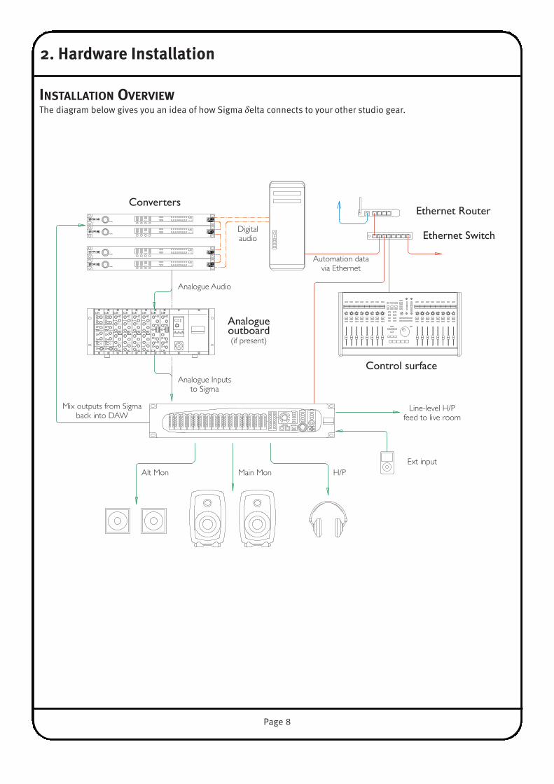
INSTALLATIoN overvIewThe diagram below gives you an idea of how Sigma δelta connects to your other studio gear.
POWERMADI RATE CLOCK LEVEL OUTPUTS INPUTS
MX16 - 4
POWERMADI RATE CLOCK LEVEL OUTPUTSINPUTS
MX4 - 16
POWERMADI RATE CLOCK LEVEL OUTPUTS INPUTS
MX16 - 4
POWERMADI RATE CLOCK LEVEL OUTPUTSINPUTS
MX4 - 16
Ext input
Control surface
Ethernet SwitchDigital audio
Mix outputs from Sigmaback into DAW
Converters
Analogueoutboard(if present)
Line-level H/Pfeed to live room
H/PAlt Mon Main Mon
Ethernet Router
Automation datavia Ethernet
Analogue Audio
Analogue Inputsto Sigma
Page 9
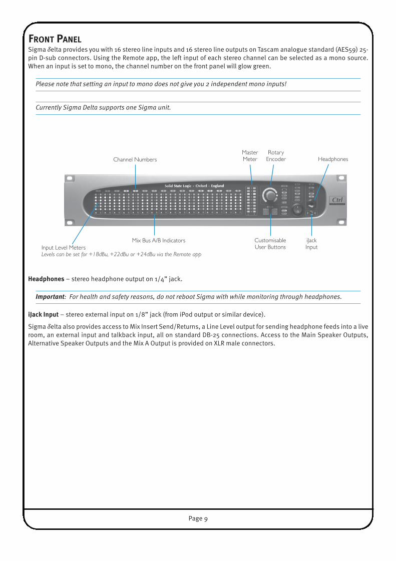
FroNT PANeLSigma δelta provides you with 16 stereo line inputs and 16 stereo line outputs on Tascam analogue standard (AES59) 25-pin D-sub connectors. Using the Remote app, the left input of each stereo channel can be selected as a mono source.When an input is set to mono, the channel number on the front panel will glow green.
Please note that setting an input to mono does not give you 2 independent mono inputs!
Currently Sigma Delta supports one Sigma unit.
Headphones – stereo headphone output on 1/4” jack.
Important: For health and safety reasons, do not reboot Sigma with while monitoring through headphones.
iJack Input – stereo external input on 1/8” jack (from iPod output or similar device).
Sigma δelta also provides access to Mix Insert Send/Returns, a Line Level output for sending headphone feeds into a liveroom, an external input and talkback input, all on standard DB-25 connections. Access to the Main Speaker Outputs,Alternative Speaker Outputs and the Mix A Output is provided on XLR male connectors.
CustomisableUser Buttons
Rotary Encoder
MasterMeter
iJackInput
HeadphonesChannel Numbers
Mix Bus A/B IndicatorsInput Level MetersLevels can be set for +18dBu, +22dBu or +24dBu via the Remote app
Page 10
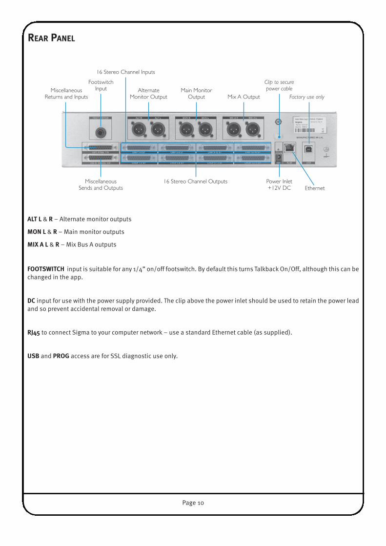
reAr PANeL
ALT L & r – Alternate monitor outputs
moN L & r – Main monitor outputs
mIX A L & r – Mix Bus A outputs
FooTSwITCH input is suitable for any 1/4” on/off footswitch. By default this turns Talkback On/Off, although this can bechanged in the app.
DC input for use with the power supply provided. The clip above the power inlet should be used to retain the power leadand so prevent accidental removal or damage.
rJ45 to connect Sigma to your computer network – use a standard Ethernet cable (as supplied).
USb and ProG access are for SSL diagnostic use only.
AlternateMonitor Output
Main MonitorOutput Mix A Output
FootswitchInput
Clip to securepower cable
Factory use only
Power Inlet+12V DC
MiscellaneousSends and Outputs
MiscellaneousReturns and Inputs
16 Stereo Channel Outputs
16 Stereo Channel Inputs
Ethernet
Page 11
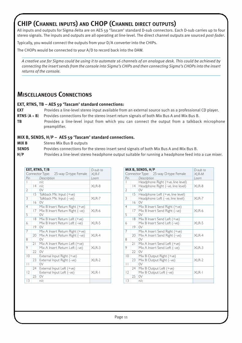
CHIP (CHANNeL INPUTS) AND CHoP (CHANNeL DIreCT oUTPUTS)All inputs and outputs for Sigma δelta are on AES 59 ‘Tascam’ standard D-sub connectors. Each D-sub carries up to fourstereo signals. The inputs and outputs are all operating at line-level. The direct channel outputs are sourced post-fader.
Typically, you would connect the outputs from your D/A converter into the CHIPs.
The CHOPs would be connected to your A/D to record back into the DAW.
A creative use for Sigma could be using it to automate 16 channels of an analogue desk. This could be achieved byconnecting the insert sends from the console into Sigma’s CHIPs and then connecting Sigma’s CHOPs into the insertreturns of the console.
mISCeLLANeoUS CoNNeCTIoNS
eXT, rTNS, Tb – AeS 59 ‘Tascam’ standard connections:eXT Provides a line-level stereo input available from an external source such as a professional CD player.rTNS (A + b) Provides connections for the stereo insert return signals of both Mix Bus A and Mix Bus B.Tb Provides a line-level input from which you can connect the output from a talkback microphone
preamplifier.
mIX b, SeNDS, H/P – AeS 59 ‘Tascam’ standard connections.mIX b Stereo Mix Bus B outputsSeNDS Provides connections for the stereo insert send signals of both Mix Bus A and Mix Bus B. H/P Provides a line-level stereo headphone output suitable for running a headphone feed into a cue mixer.
eXT, rTNS, T/b D-sub toXLR-F Loom
Connector Type: 25-way D-type FemalePin Description1 n/c
XLR-814 n/c2 0V
15 Talkback Mic Input (+ve)XLR-73 Talkback Mic Input (–ve)
16 0V4 Mix B Insert Return Right (+ve)
XLR-617 Mix B Insert Return Right (–ve)5 0V
18 Mix B Insert Return Left (+ve)XLR-56 Mix B Insert Return Left (–ve)
19 0V7 Mix A Insert Return Right (+ve)
XLR-420 Mix A Insert Return Right (–ve)8 0V
21 Mix A Insert Return Left (+ve)XLR-39 Mix A Insert Return Left (–ve)
22 0V10 External Input Right (+ve)
XLR-223 External Input Right (–ve)11 0V
24 External Input Left (+ve)XLR-112 External Input Left (–ve)
25 0V13 n/c
mIX b, SeNDS, H/P D-sub toXLR-M Loom
Connector Type: 25-way D-type FemalePin Description1 Headphone Right (+ve, line level)
XLR-814 Headphone Right (–ve, line level)2 0V
15 Headphone Left (+ve, line level)XLR-73 Headphone Left (–ve, line level)
16 0V4 Mix B Insert Send Right (+ve)
XLR-617 Mix B Insert Send Right (–ve)5 0V
18 Mix B Insert Send Left (+ve)XLR-56 Mix B Insert Send Left (–ve)
19 0V7 Mix A Insert Send Right (+ve)
XLR-420 Mix A Insert Send Right (–ve)8 0V
21 Mix A Insert Send Left (+ve)XLR-39 Mix A Insert Send Left (–ve)
22 0V10 Mix B Output Right (+ve)
XLR-223 Mix B Output Right (–ve)11 0V
24 Mix B Output Left (+ve)XLR-112 Mix B Output Left (–ve)
25 0V13 n/c
Page 12
3. Software Installation and Configuration
Sigma δelta requires the following software to be installed onto your computer:
• Sigma remote app – control of your Sigma δelta
• δ-Ctrl plug-in – to automate Sigma δelta channel volume and mutes directly from a DAW
• ipmIDI software – Direct hardware control of Sigma from a compatible networked control surface using the MCU(Mackie Control Unit) protocol
• Nucleus remote – Only required if using an SSL Nucleus as a remote control surface.
Locate either the SSL Delta Control.dmg disk image (Macintosh) or the SSL Delta Control Setup.zip file (Windows),included as part of the Sigma downloads – these contain the Sigma Remote and ipMIDI applications, the plug-in installer,the Nucleus Remote profile and the latest version of the installation and operating instructions.
The files can be downloaded from the Update section of SSL’s website here: Update
Please note: to access the Update section, the Sigma δelta unit must be registered to a user account.
INSTALLING THe remoTe APP
remote App (macintosh)Open the disk image and then the Sigma Remote Control.pkg;follow the installation steps in the installer.
remote App (windows)Open the zip file and run the SSL Sigma Remote.exe file;follow the installation steps in the installer.

Page 13
INSTALLING THe δeLTA-CoNTroL PLUG-IN
δ-Ctrl Plug-in (macintosh)Open the disk image and mount the SSL Delta Control Plug-in.pkg; follow the installation steps as shown below:
δ-Ctrl Plug-in (windows)Open the zip file and run the SSL Delta Control Setup.exe file; follow the installation steps as shown below:
iLokThe plug-in uses the industry standard iLok copy protection scheme – users will need an iLok2 USB key.
In the case of a new unit 1 licence is included as standard, additional licences are be available from the SSL web store.Existing V1.0.3 customers will need to purchase a license from the SSL web store.

INSTALLING IPmIDI SoFTwAre
ipmIDI (macintosh)After downloading the Sigma Mac Support File from the Downloadssection, install the ipMIDI.dmg file. Note that you will be asked tologout and in again once you have completed the installation. Onceyou have logged back in open Audio mIDI Setup (in the Utilitiesfolder on your Mac) and double click on the ipMIDI icon (in MIDIWindow view). Set the number of ports to 20 in the resulting pop-up.
There are two version of ipMIDI for Mac: V1.5 is suitable for OS X10.5 whilst V1.6 runs on OS X 10.6 upwards. Please choose thecorrect version for your Mac.
If you are upgrading an older copy of ipMIDI you must uninstall it before running the installer. To uninstall ipMIDIsimple delete: ‘/Library/Audio/MIDI Drivers/ipMIDIDriver.plugin’. You should empty the Trash after deleting the‘.plugin’ file before running the installer.
ipmIDI (windows)After downloading the Sigma Windows Support File from the downloads page, install theipMIDI.exe. Note that you will have to restart the computer at the end of the setup process.Once the computer has restarted, double-click on the ipMIDI icon in the bottom-right taskbarof Windows and set the number of MIDI ports to 20 in the resulting pop-up.
Note that if you are upgrading an older copy of ipMIDI you must uninstall (using Add/Removeprograms) it before running the installer.
NUCLeUS remoTe ProFILeIn the Nucleus Remote click on Edit Profiles to bring up the Profile Editor popup and click Restore. In the pop-up whichappears, locate the file Sigma Delta.zip from the software download and click on Open. The restored Profile will appearin the Profile list which can be assigned to a Nucleus layer in the usual manner.
Note that you must have a working USB connection between Nucleus and the DAW computer for these features to work
SIGmA’S INTerNAL SoFTwAreSigma δelta has internal software that comes pre-installed from the factory. There may be infrequent updates for thissoftware. Please refer to Section 5, page 31: ‘Software Update’ for more information on how to check your Sigma softwareversion and how to update the software.
Page 14

4. Network Setup
GeNerALSigma δelta communicates with its Remote app and the δelta-Control plug-in over a standard TCP/IP Ethernet connection.
The ipMIDI software driver – required to run MCU control – uses multicast UDP, rather than TCP/IP, to ensure minimumlatency. Routers that support high data transfer rates should be used. Some domestic routers have experienced problems,so please check your router specification if problems occur. See following note.
Notes for Network Technicians:Because ipMIDI uses multicast UDP packets, messages between one computer and Sigma will be received by allother computers on the network, potentially causing problems with other ipMIDI devices on your network. The UDPpackets can be blocked by using a firewall router and connecting the main network by the WAN connector. The firewallcan then be configured to allow all traffic apart from UDP ports 21928 through 21947 which are used by ipMIDI. Notethat it may be necessary to use a separate Ethernet switch in place of an integrated firewall router switch, as someof these can not support the high data transfer rate required. A pre-configured LAN Integration Network Switch can be purchased from the SSL web store. Also see setup example 3 on page 19 for more details.
Sigma’s IP AddressBy default, Sigma uses a fixed IP address of 192.168.1.201. Alternatively, Sigma can be set to use a dynamically assigned(DHCP) address if your installation precludes a simple direct connection. Switching between the two options is done inSigma’s SeTTINGS page in the app.
Useful built-In Features reverting from DHCP to Fixed IPIf a situation arises where Sigma δelta is set to DHCP but you are unable to connect via a DHCP, take the following steps:
1. Power Sigma off2. Set your computer network settings to be a fixed IP address3. Power Sigma on
This will force Sigma into reverting to its fixed IP address.
How to Check the Current IP Address of Sigma δeltaOnce connected to Sigma, it is possible to change the fixed IP address as desired. In a situation whereyou forget what the fixed IP address is set to, press and hold the first USer button on the front paneland whilst keeping this held down, press the second USer button. Sigma will use the front panel LEDsto readout the IP address it is set to.
Page 15

Page 16
NeTwork CoNNeCTIoN eXAmPLeS
1. Fixed IP – Direct Connection This is the simplest way to setup Sigma with your computer. Sigma comes configured to use a fixed IP on first startup.
Please note that Macintosh computers with multiple Ethernet ports can only use one of those ports at any one time!
Using mac ‘Airport’ and ipmIDIIf you are using a Macintosh computer, you should ensure that Airport is switched off. Westrongly recommend this as Airport is known to cause conflicts with ipMIDI data and maystop Sigma from working. If you wish to use the internet, we suggest you configure Sigmawith a Router/Switch (see example 2).
DAWComputer
EthernetConnection

Page 17
Network Connection Configuration – macintosh• On your computer go to System Preferences and click on the Network icon.• Set Configure IPv4 to manually then fill in the IP Address and Subnet mask boxes with the numbers shown. The IP
address should be in the 192.168.1.X range with a Subnet of 255.255.255.0.
‘X' should be a number between 3 and 254. Make sure that the ‘X’ number is not the same as Sigma’s address, orany other device on the network.
Network Connection Configuration – windows• Go to Network and go into Local Area Connection Properties.• Open up the option Internet Protocol version 4 (TCP/IPv4). • Select Use the following IP address and then fill in the IP Address and Subnet mask boxes as shown below.
Page 18
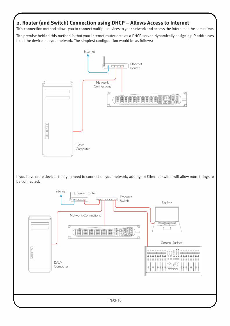
2. router (and Switch) Connection using DHCP – Allows Access to InternetThis connection method allows you to connect multiple devices to your network and access the internet at the same time.
The premise behind this method is that your Internet router acts as a DHCP server, dynamically assigning IP addressesto all the devices on your network. The simplest configuration would be as follows:
If you have more devices that you need to connect on your network, adding an Ethernet switch will allow more things tobe connected.
Internet
EthernetRouter
NetworkConnections
DAWComputer
Internet Ethernet RouterEthernetSwitch
Control Surface
Network Connections
Laptop
DAWComputer
Page 19
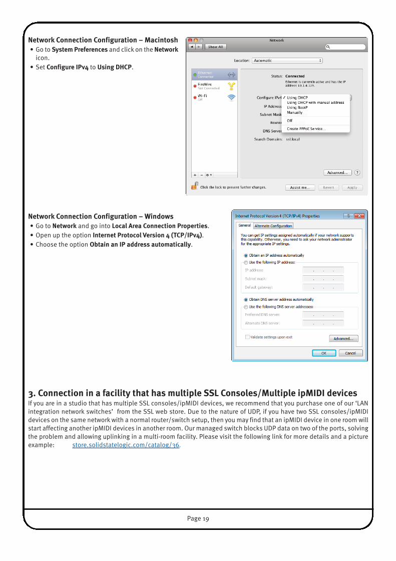
Network Connection Configuration – macintosh• Go to System Preferences and click on the Network
icon.• Set Configure IPv4 to Using DHCP.
Network Connection Configuration – windows• Go to Network and go into Local Area Connection Properties.• Open up the option Internet Protocol version 4 (TCP/IPv4).• Choose the option obtain an IP address automatically.
3. Connection in a facility that has multiple SSL Consoles/multiple ipmIDI devicesIf you are in a studio that has multiple SSL consoles/ipMIDI devices, we recommend that you purchase one of our ‘LANintegration network switches’ from the SSL web store. Due to the nature of UDP, if you have two SSL consoles/ipMIDIdevices on the same network with a normal router/switch setup, then you may find that an ipMIDI device in one room willstart affecting another ipMIDI devices in another room. Our managed switch blocks UDP data on two of the ports, solvingthe problem and allowing uplinking in a multi-room facility. Please visit the following link for more details and a pictureexample: store.solidstatelogic.com/catalog/36.

SySTem workFLow TIPSThis is a suggested workflow for the Sigma Delta system, incorporating Sigma hardware, Remote app, δelta-Control plug-in, control surface and DAW.
boot orderIt is recommended to boot Sigma, control surface and the Remote app before the DAW and δelta-Control plug-ins. If at anypoint Sigma, the control surface or the Remote app is closed/rebooted with the DAW and δelta-Control plug-ins open, thesystem should be booted from the start to ensure proper communication.
The Remote app must be open on your DAW PC/Mac at all times in order for an SSL control surface and the δelta-Controlplug-ins to communicate. This includes situations where an iOS or OSC device is being used to control Sigma.
Channel NamesContrary to the previous Sigma software (v1.0.3.x) channel names are no longer read from the DAW when the δelta protocolis in use. You will notice that the NAMES: DAW button is greyed out in the Remote app in δelta mode.
Channel names should be entered manually in the Remote app using the computer keyboard. When a δelta Plug-in isassigned to that Sigma channel in the DAW the channel name is displayed on the left hand side of the top panel.
δelta Plug-insIt is recommended that these are inserted and assigned a channel at the beginning of the session. Do not copy a plug-into another insert slot once it has been assigned to a channel as this can disrupt the connection to Sigma. Using the auto-increment feature of the plug-in is recommended. See section 6 of this User Guide for detailed information on the δeltaPlug-in.
Sigma δelta Nucleus ProfileA Nucleus Profile is included in the software download package. This maps some Sigma controls to Nucleus switches foreasy access from the control surface, as shown:
mIX A = F1 CUT = SAVEmIX b = F2 ALT L/S = UNDODIm = ENTER T/b = CTRLmoNo = ESC
The MIX A and MIX B channel assignments are used in conjunction with the Nucleus SEL switch.
The talkback (T/B) function is non-latching.
An SSL Nucleus (or other compatible MCU controller) needs one of its DAW layers dedicated to Sigma. This is assigned inthe Sigma Remote app.
If, for example, you want to use Nucleus DAW layer 2 to communicate with Sigma, ipMIDI ports 3+4 should be assignedto Channels 1-8 and 9-16 respectively in the Sigma Remote app.
SSL Console Transport masterWhen your DAW is assigned to one SSL console DAW layer and Sigma to another, toretain transport control when the Sigma layer is in focus assign the transport masterto the DAW layer. Click on the appropriate button in the Transport Master area of theconsole Remote’s DAW tab to assign this to your DAW layer.
Page 20
DAW Sigma MIDI CC
UPGrADING From SIGmA 1.0.3.X To SIGmA δeLTA
web browser InterfaceThis method of controlling Sigma remains available to allow translation of Sigma settings to the Remote app.
Important: The web browser interface should be closed at all times except when copying settings as outlined below.Leaving it open can disrupt proper communication in the Delta system.
Copying Sigma Settings from earlier softwareSigma settings stored with v1.0.3.x software or earlier can be recalled via the web browser using the Load tab. It isrecommended to re-save the settings in the Remote app for further use.
Translating Sigma v1.0.3.x Automation to the δelta SystemIf you have DAW projects that you wish to continue using with the δelta system, the automation data must be translatedto the Delta plug-in in the DAW.
Pro Tools (HUI):• View and select the track Volume automation data• Edit > Copy (or Cut)• Change automation view to SSL δelta Control (Volume)• Edit > Paste Special > To Current Automation Type • Do this for each of the 16 Sigma channels
Cubase, Nuendo and Ableton Live:• View and select the track Volume automation data• Edit > Copy (or Cut)• Change automation view to SSL δelta Control (Volume)• Edit > Paste • Do this for each of the 16 Sigma channels
Page 21

Page 22
5. Sigma δelta operation
THe remoTe APP INTerFACeOnce the app is running and connected, you have access to all of Sigma’s functions. The interface is arranged as follows:
Three Buttons for Sigma’sOperational Control
Buttons for Saving andRecalling Settings

mASTerWhen launching the Remote app you will be looking at the mASTer page. Most functions that can be set by the app – suchas monitoring source or insert points in/out – will also be reflected on Sigma δelta’s front panel.
master meterThe front panel Master Meter is to the right of the 16channels. The ‘0’ mark indicates 0 dBFS (default is+24dBu). Master and channel meter calibration can be setglobally in the SETTINGS page.
The app allows you to switch the master meter sourcebetween the following: moN Master Meter follows the current monitoring
source(s)mIX A Lock the Master Meter to follow the post-
fader level of Mix Bus AmIX b Locks the Master Meter to follow the post-
fader level of Mix Bus B
mix bus InsertsThe Mix A and Mix B insert points are enabled byclicking on the mIX A and mIX b buttons inside theINSerT box. Inserts have a ‘Σ’ function which sumsthe insert return with the original main stereo mix bussignal. This may be useful for a several reasons: it willallow you to link the mix busses of two Sigmastogether by connecting the mix bus output from thesecond Sigma into the insert return of the first Sigma;or you could use this function with one Sigma to createa parallel compression effect, using the compressor’soutput level to control the amount of compressedsignal present.
Level ControlThe front panel of Sigma has a blue rotary encoder,surrounded by an LED ring. Pushing the encoder in willcycle through the options moN, H/P, mIX A and mIX b,enabling independent level control of each one.moN Main/Alternate monitor levelH/P Headphones output levelmIX A Mix Bus A levelmIX b Mix Bus B level
When setting the level of Mix A or Mix B, the dot thatbreaks up the LED ring will light red to indicate 0dB.
Push and hold the rotary encoder for two seconds, then release. The dimly lit LEDring now indicates that you are in Fine adjustment mode
Coarse: level steps in 0.5 dBFine: level steps in 0.1dB
Pushing and holding the rotary encoder again will return it to Coarse operation.
The rotary encoder is speed-sensitive; slower turns will allow you to changegains more accurately.
Page 23
SoUrCe rANGe
moN 0 to 12
H/P 0 to 12
mIX A -� to +10dB (red dot indicates 0dB)
mIX b -� to +10dB (red dot indicates 0dB)
App Control Panel
mIDILearn
Footswitch(F/S) Box
Headphone(H/P) Box
monBox
InsertSelection
UserButtons
LevelAssignment
MeterSource
LevelIndicator
DImBox
PowerButton
iJackInput
InsertBox
UserButtons
Headphone(H/P) Box
monBox
LevelBox
MasterMeter
RotaryEncoder
Unit Front Panel
Page 24
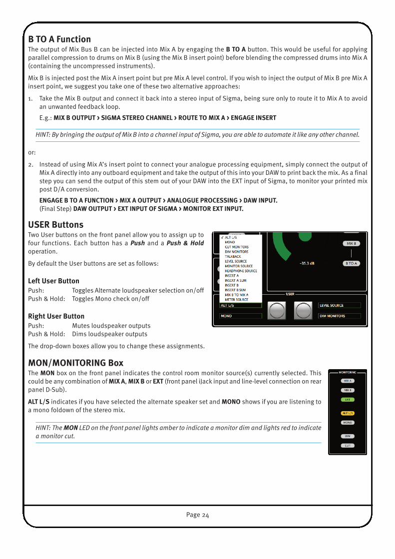
b To A FunctionThe output of Mix Bus B can be injected into Mix A by engaging the b To A button. This would be useful for applyingparallel compression to drums on Mix B (using the Mix B insert point) before blending the compressed drums into Mix A(containing the uncompressed instruments).
Mix B is injected post the Mix A insert point but pre Mix A level control. If you wish to inject the output of Mix B pre Mix Ainsert point, we suggest you take one of these two alternative approaches:
1. Take the Mix B output and connect it back into a stereo input of Sigma, being sure only to route it to Mix A to avoidan unwanted feedback loop.
E.g.: mIX b oUTPUT > SIGmA STereo CHANNeL > roUTe To mIX A > eNGAGe INSerT
HINT: By bringing the output of Mix B into a channel input of Sigma, you are able to automate it like any other channel.
or:
2. Instead of using Mix A’s insert point to connect your analogue processing equipment, simply connect the output ofMix A directly into any outboard equipment and take the output of this into your DAW to print back the mix. As a finalstep you can send the output of this stem out of your DAW into the EXT input of Sigma, to monitor your printed mixpost D/A conversion.
eNGAGe b To A FUNCTIoN > mIX A oUTPUT > ANALoGUe ProCeSSING > DAw INPUT. (Final Step) DAw oUTPUT > eXT INPUT oF SIGmA > moNITor eXT INPUT.
USer buttonsTwo User buttons on the front panel allow you to assign up tofour functions. Each button has a Push and a Push & Holdoperation.
By default the User buttons are set as follows:
Left User button Push: Toggles Alternate loudspeaker selection on/offPush & Hold: Toggles Mono check on/off
right User button Push: Mutes loudspeaker outputsPush & Hold: Dims loudspeaker outputs
The drop-down boxes allow you to change these assignments.
moN/moNITorING boxThe moN box on the front panel indicates the control room monitor source(s) currently selected. Thiscould be any combination of mIX A, mIX b or eXT (front panel iJack input and line-level connection on rearpanel D-Sub).
ALT L/S indicates if you have selected the alternate speaker set and moNo shows if you are listening toa mono foldown of the stereo mix.
HINT: The MON LED on the front panel lights amber to indicate a monitor dim and lights red to indicatea monitor cut.
Page 25
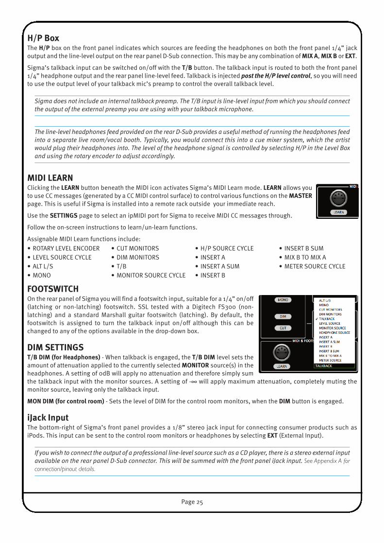
H/P boxThe H/P box on the front panel indicates which sources are feeding the headphones on both the front panel 1/4” jackoutput and the line-level output on the rear panel D-Sub connection. This may be any combination of mIX A, mIX b or eXT.
Sigma’s talkback input can be switched on/off with the T/b button. The talkback input is routed to both the front panel1/4” headphone output and the rear panel line-level feed. Talkback is injected post the H/P level control, so you will needto use the output level of your talkback mic’s preamp to control the overall talkback level.
Sigma does not include an internal talkback preamp. The T/B input is line-level input from which you should connectthe output of the external preamp you are using with your talkback microphone.
The line-level headphones feed provided on the rear D-Sub provides a useful method of running the headphones feedinto a separate live room/vocal booth. Typically, you would connect this into a cue mixer system, which the artistwould plug their headphones into. The level of the headphone signal is controlled by selecting H/P in the Level Boxand using the rotary encoder to adjust accordingly.
mIDI LeArNClicking the LeArN button beneath the MIDI icon activates Sigma’s MIDI Learn mode. LeArN allows youto use CC messages (generated by a CC MIDI control surface) to control various functions on the mASTerpage. This is useful if Sigma is installed into a remote rack outside your immediate reach.
Use the SeTTINGS page to select an ipMIDI port for Sigma to receive MIDI CC messages through.
Follow the on-screen instructions to learn/un-learn functions.
Assignable MIDI Learn functions include:
FooTSwITCHOn the rear panel of Sigma you will find a footswitch input, suitable for a 1/4” on/off(latching or non-latching) footswitch. SSL tested with a Digitech FS300 (non-latching) and a standard Marshall guitar footswitch (latching). By default, thefootswitch is assigned to turn the talkback input on/off although this can bechanged to any of the options available in the drop-down box.
DIm SeTTINGST/b DIm (for Headphones) - When talkback is engaged, the T/b DIm level sets theamount of attenuation applied to the currently selected moNITor source(s) in theheadphones. A setting of 0dB will apply no attenuation and therefore simply sumthe talkback input with the monitor sources. A setting of -∞ will apply maximum attenuation, completely muting themonitor source, leaving only the talkback input.
moN DIm (for control room) - Sets the level of DIM for the control room monitors, when the DIm button is engaged.
iJack InputThe bottom-right of Sigma’s front panel provides a 1/8” stereo jack input for connecting consumer products such asiPods. This input can be sent to the control room monitors or headphones by selecting eXT (External Input).
If you wish to connect the output of a professional line-level source such as a CD player, there is a stereo external inputavailable on the rear panel D-Sub connector. This will be summed with the front panel iJack input. See Appendix A forconnection/pinout details.
• ROTARY LEVEL ENCODER• LEVEL SOURCE CYCLE• ALT L/S• MONO
• CUT MONITORS• DIM MONITORS• T/B• MONITOR SOURCE CYCLE
• H/P SOURCE CYCLE • INSERT A• INSERT A SUM• INSERT B
• INSERT B SUM• MIX B TO MIX A• METER SOURCE CYCLE
Page 26
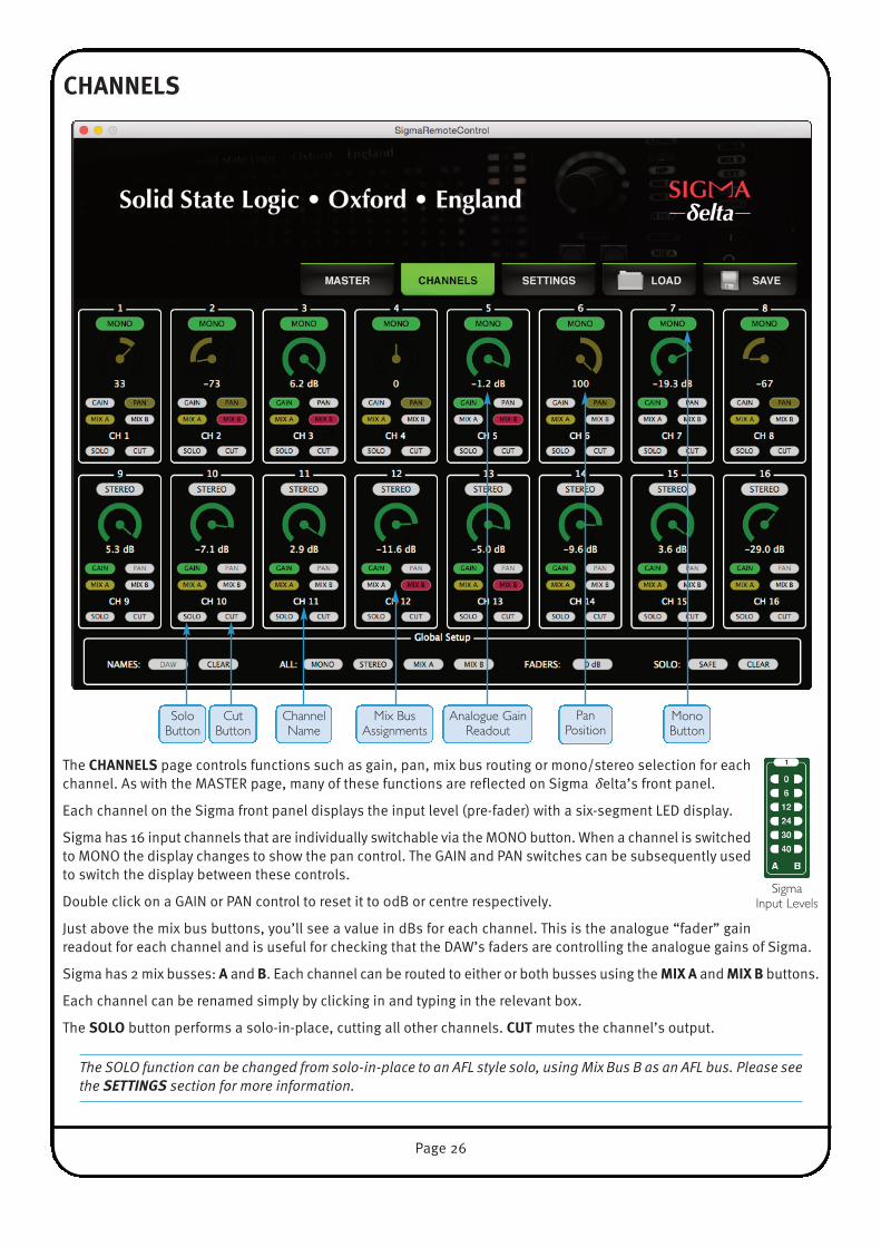
CHANNeLS
The CHANNeLS page controls functions such as gain, pan, mix bus routing or mono/stereo selection for eachchannel. As with the MASTER page, many of these functions are reflected on Sigma δelta’s front panel.
Each channel on the Sigma front panel displays the input level (pre-fader) with a six-segment LED display.
Sigma has 16 input channels that are individually switchable via the MONO button. When a channel is switchedto MONO the display changes to show the pan control. The GAIN and PAN switches can be subsequently usedto switch the display between these controls.
Double click on a GAIN or PAN control to reset it to 0dB or centre respectively.
Just above the mix bus buttons, you’ll see a value in dBs for each channel. This is the analogue “fader” gainreadout for each channel and is useful for checking that the DAW’s faders are controlling the analogue gains of Sigma.
Sigma has 2 mix busses: A and b. Each channel can be routed to either or both busses using the mIX A and mIX b buttons.
Each channel can be renamed simply by clicking in and typing in the relevant box.
The SoLo button performs a solo-in-place, cutting all other channels. CUT mutes the channel’s output.
The SOLO function can be changed from solo-in-place to an AFL style solo, using Mix Bus B as an AFL bus. Please seethe SETTINGS section for more information.
PanPosition
Analogue GainReadout
ChannelName
SoloButton
CutButton
Mix BusAssignments
Sigma Input Levels
MonoButton
Page 27
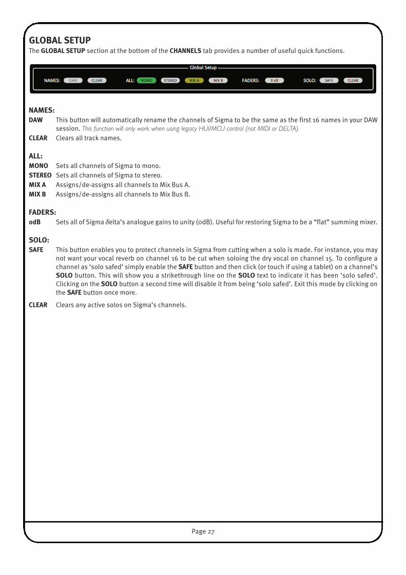
GLobAL SeTUPThe GLobAL SeTUP section at the bottom of the CHANNeLS tab provides a number of useful quick functions.
NAmeS:DAw This button will automatically rename the channels of Sigma to be the same as the first 16 names in your DAW
session. This function will only work when using legacy HUI/MCU control (not MIDI or DELTA).CLeAr Clears all track names.
ALL:moNo Sets all channels of Sigma to mono.STereo Sets all channels of Sigma to stereo.mIX A Assigns/de-assigns all channels to Mix Bus A.mIX b Assigns/de-assigns all channels to Mix Bus B.
FADerS:0db Sets all of Sigma δelta’s analogue gains to unity (0dB). Useful for restoring Sigma to be a “flat” summing mixer.
SoLo:SAFe This button enables you to protect channels in Sigma from cutting when a solo is made. For instance, you may
not want your vocal reverb on channel 16 to be cut when soloing the dry vocal on channel 15. To configure achannel as ‘solo safed’ simply enable the SAFe button and then click (or touch if using a tablet) on a channel’sSoLo button. This will show you a strikethrough line on the SoLo text to indicate it has been ‘solo safed’.Clicking on the SoLo button a second time will disable it from being ‘solo safed’. Exit this mode by clicking onthe SAFe button once more.
CLeAr Clears any active solos on Sigma’s channels.
Page 28
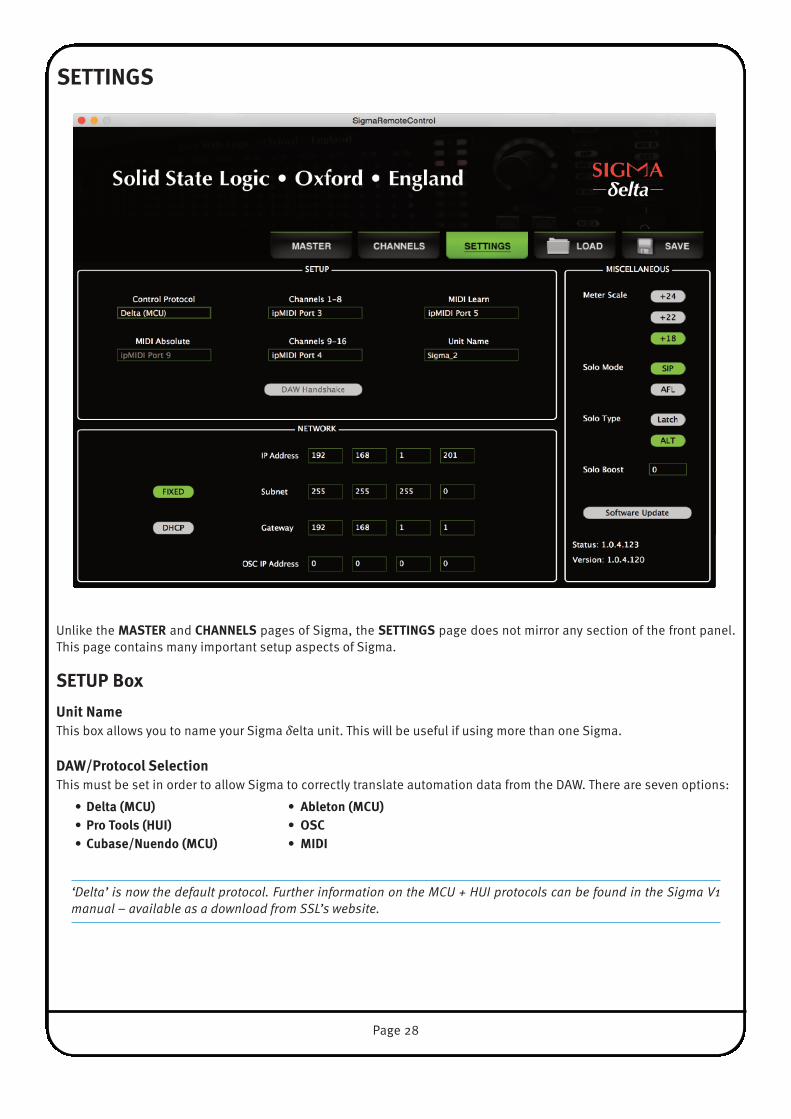
SeTTINGS
Unlike the mASTer and CHANNeLS pages of Sigma, the SeTTINGS page does not mirror any section of the front panel.This page contains many important setup aspects of Sigma.
SeTUP boxUnit NameThis box allows you to name your Sigma δelta unit. This will be useful if using more than one Sigma.
DAw/Protocol Selection This must be set in order to allow Sigma to correctly translate automation data from the DAW. There are seven options:
• Delta (mCU) • Ableton (mCU)• Pro Tools (HUI) • oSC• Cubase/Nuendo (mCU) • mIDI
‘Delta’ is now the default protocol. Further information on the MCU + HUI protocols can be found in the Sigma V1manual – available as a download from SSL’s website.

Page 29
ipmIDI PortsCHANNeLS 1-8 Select the ipMIDI Port number corresponding to the master section and channels 1-8 of the MCU
controller layer designated for Sigma communication.
CHANNeLS 9-16 Select the ipMIDI Port number corresponding to channels 9-16 of the MCU controller layer designatedfor Sigma communication.
In Delta (MCU) Protocol, these are matched to your control surface ipMIDI ports. In Pro Tools, Cubase, Nuendo andAbleton protocols, these are matched to the HUI/MCU units assigned in your DAW.
mIDI AbsoluteThe mIDI Absolute box will become available if mIDI is selected in the DAw/ProToCoL drop-down list. mIDI Absoluteoffers an alternative way of controlling Sigma’s analogue gains directly from the DAW. Instead of using the Delta controlplug-in or receiving volume messages over the HUI/MCU protocol, mIDI Absolute works by receiving MIDI volumemessages directly from the outputs of MIDI tracks within the DAW. Set the MIDI Absolute ipMIDI port to be the same asthe ipMIDI port that your 16 MIDI Track outputs are set to in the DAW.
Note the Channels 1-8 and Channels 9-16 drop-down boxes have no effect when MIDI is being used.
mIDI LearnMany functions on the mASTer page of Sigma can be enabled/disabled from an external MIDI controller sending CCmessages (e.g. the CC layer available on an SSL Nucleus). You should set this drop-down to match the ipMIDI port numberfrom which the MIDI CC messages are being sent on. For instance, if Nucleus’ CC layer is setup on DAW Layer 3, this drop-down should be set to ipmIDI Port 5.
The mIDI Learn drop down box only allows access to ipMIDI ports. If you wish to use a MIDI device/interface that does notuse ipMIDI, you can download a free program called ‘MIDI Patchbay’ to route the output of your chosen MIDI device intoan ipMIDI port.

Page 30
NeTwork boxYou are able to choose between a FIXeD IP address or DHCP configuration. The static IP address of Sigma defaults to192.168.1.201. Please see NeTwork SeTUP section for more information.
mISCeLLANeoUS boxThis section contains a number of miscellaneous settings.
meter ScaleMeter scaling is applied globally to all channel meters and the master meter. Set to match the 0dBFS reference of yourA/D D/A converter. The three options are: +24dBu, +22dBu or + 18dBu. By default, Sigma is set to +24dBu = 0dBFS.
Solo modeThis controls how the SoLo function works in the CHANNeLS page. If you are unfamiliar with different solo modes thenthe following explains the differences between the two:
SIP (Solo-In-Place) Soloing a channel causes all other channels to be muted.
AFL (After Fader Level) Soloing a channel moves that signal onto a separate stereo mix bus, normally known as the AFLbus.
Sigma does not have a dedicated AFL bus. However, selecting the AFL option in SoLo moDe will hijack Mix Bus B and usethis as an AFL bus. Sigma will automatically switch the monitor source selection to Mix Bus B when soloing in this mode.
AFL is useful when you want to solo a channel just to check something whilst printing a mix back into the DAW. If you wereto use SIP, you would disrupt the printing process as soloing in this mode mutes all other channels.
Please note that if you are operating Sigma in AFL Solo Mode, you will be unable to route channels to Mix Bus B. Also,upon changing to AFL Solo Mode, any channels currently routed to Mix Bus B will be un-routed.
By default, Sigma is set to SIP (Solo-In-Place).
Solo TypeLATCH When one channel is in solo, pressing a second SoLo button adds this channel to the first rather than cancelling
the original channel.ALT When ALT is selected the SoLo buttons are prevented from latching, introducing inter-cancellation between
SoLo buttons: pressing a second SoLo button cancels the first SoLo.
By default, Sigma is set to LATCH.
Solo boostAutomatically increases the monitor level by the set amount when a SoLo is activated (range 0 - 10dB). This is useful whenmixing to help reduce the level difference apparent when changing from listening to the whole mix to just one soloedchannel.
Page 31
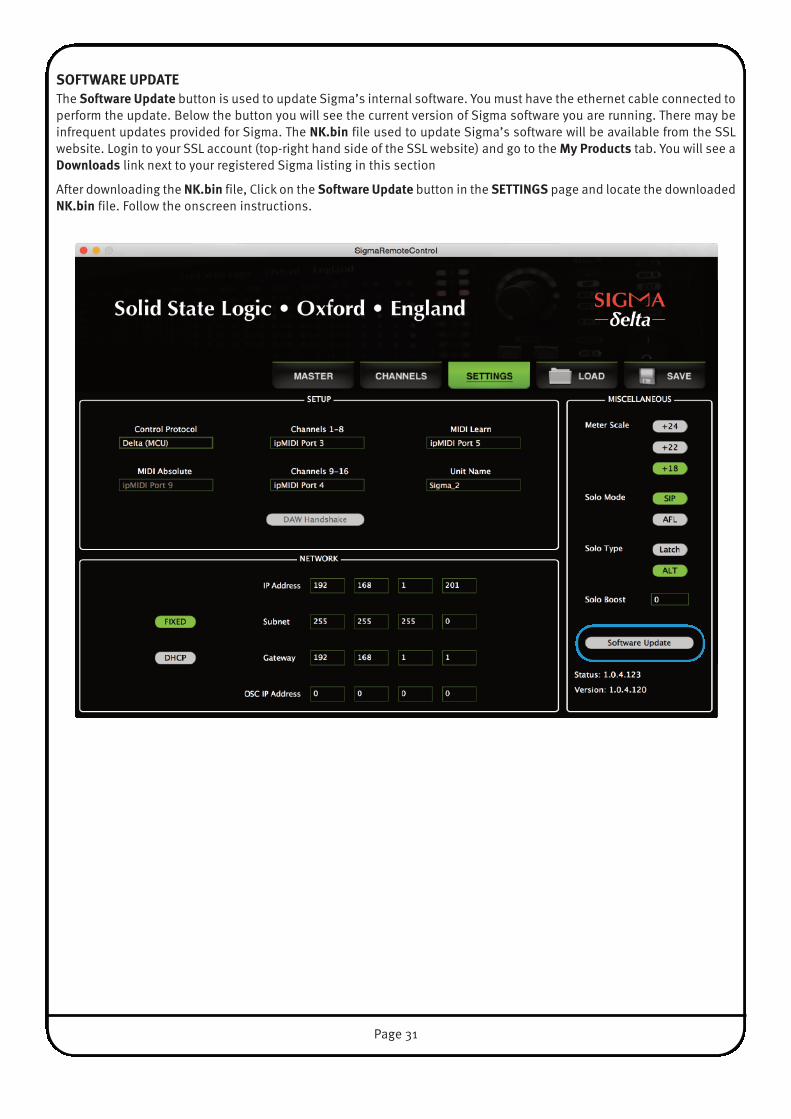
SoFTwAre UPDATeThe Software Update button is used to update Sigma’s internal software. You must have the ethernet cable connected toperform the update. Below the button you will see the current version of Sigma software you are running. There may beinfrequent updates provided for Sigma. The Nk.bin file used to update Sigma’s software will be available from the SSLwebsite. Login to your SSL account (top-right hand side of the SSL website) and go to the my Products tab. You will see aDownloads link next to your registered Sigma listing in this section
After downloading the Nk.bin file, Click on the Software Update button in the SeTTINGS page and locate the downloadedNk.bin file. Follow the onscreen instructions.

Page 32
rebooT bUTToNWhen you make a change in the SeTTINGS page that requires Sigma to be restarted in order for the change to have effect,a message will prompt you to perform a restart. The Software Update button will temporarily change to a rebooT button.Click this to restart Sigma.
SAve AND LoAD bUTToNSThe SAve button will save all of Sigma’s settings across the three main pages - mAIN,CHANNeLS and SeTTINGS.
Upon clicking the SAve button you will be presented with a pop-up asking you to namethe file and choose a destination on your computer/network.
The LoAD button enables you to recall a previously saved Sigma setup.
Upon clicking the LoAD button you will be prompted to locate a saved Sigma file from your computer/network.
Sigma files are saved as .xml type files.

Page 33
6. Sigma δelta-Control Automation
overvIewδ-Ctrl is a native AAX/RTAS/VST/VST3 plug-in that allows the user to automate Sigma channel Volume and Mute data, asthough they were standard DAW Plug-in parameters. The δ-Ctrl plug-in is inserted into a DAW mixer channel, which thenreceives and sends control data for the assigned Sigma channel via a high speed Network connection. Any associatedaudio on the track is unaffected and passes through the plug-in slot unprocessed.
The channel volume and mutes are represented as plug-in parameters and will have automation data saved in theassociated plug-in track automation playlist. This data together with any associated automation record enable commandsgenerated from an MCU surface connected to Sigma are streamed via the same network connection that carries ipMidiand the Remote app messages using proprietary SSL Logictivity Network protocols. The plug-in decodes the messages andconverts them to conventional plug-in parameter values, which can be saved as automation streams in the DAW track. InAutomation Playback the plug-in converts the stored automation data, from the DAW automation playlists, into δ-Ctrlmessages and routes these back to Sigma via the Logictivity Network connection.
These automation playlists can be viewed and edited as normal plug-in data in the DAW tracks and will be saved alongsidethe rest of the session data. The Plug-in’s data values are expressed in dB units for faders or as text for the mutes, whichrelate directly to the parameter being controlled when automation moves are viewed in the track automation lanes forediting. Sigma Volume data is saved using the same dB law as Pro Tools Fader automation so that the ‘Paste Special’command can be used to copy existing Pro Tools fader data into the plug-in. This feature is DAW specific and may notnecessarily be available with other systems.
THe δeLTA-CoNTroL ADvANTAGe• All fader moves are captured and played with the same accuracy as any other DAW automation parameter • True 10 bit fader resolution.• TCP/IP Network based UDP control protocol - not embedded MIDI messages.• DAW editing tools can be used to draw and edit console fader and switch automation data.• Sigma Channel levels and mutes are automatically reset when a DAW project is loaded.• The system is class compliant, no driver installation is required.
workSTATIoN SeTUP – Pro TooLSBefore mixing with the plug-in, the following options should be enabled in the Pro Tools Setup / Preferences / Mixingmenu :
1. Plug-in Controls Default to Auto-Enabled – Otherwise the parameters will need to be manually enabled for automation from eachindividual plug-in window either manually or using the Command-Option-Control-click (MAC) or Control-Alt-Start-click (PC) short cut.
2. Latching Behaviour for Switch Controls in Touch – This ensure that console switch automation is recorded correctly when thetrack automation mode is set to Touch.
3. Set the SSL δ-Ctrl Plug-in as a Favourite by Command-click (Mac) or Control-click (PC) the Insert Selector and thenselecting the SSL plug-in from the Other category. It will then appear at the top of the Insert Selector pop-up menufor fast access.
Page 34
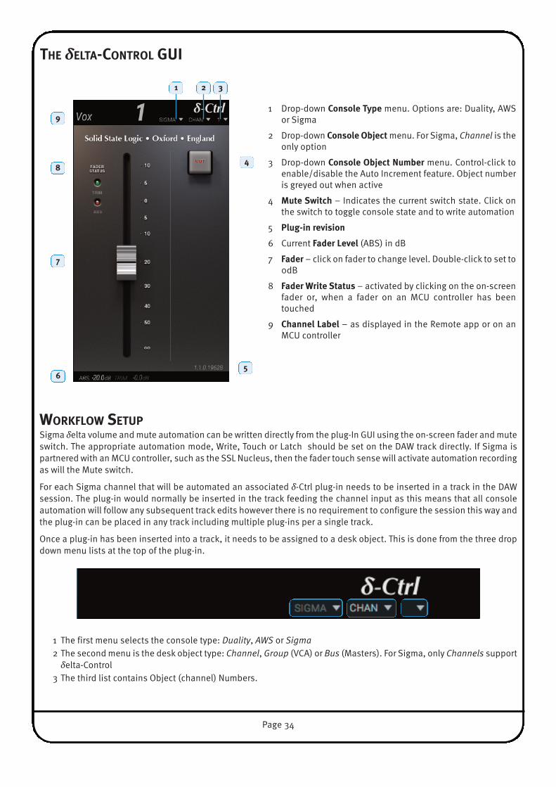
THe δeLTA-CoNTroL GUI
workFLow SeTUPSigma δelta volume and mute automation can be written directly from the plug-In GUI using the on-screen fader and muteswitch. The appropriate automation mode, Write, Touch or Latch should be set on the DAW track directly. If Sigma ispartnered with an MCU controller, such as the SSL Nucleus, then the fader touch sense will activate automation recordingas will the Mute switch.
For each Sigma channel that will be automated an associated δ-Ctrl plug-in needs to be inserted in a track in the DAWsession. The plug-in would normally be inserted in the track feeding the channel input as this means that all consoleautomation will follow any subsequent track edits however there is no requirement to configure the session this way andthe plug-in can be placed in any track including multiple plug-ins per a single track.
Once a plug-in has been inserted into a track, it needs to be assigned to a desk object. This is done from the three dropdown menu lists at the top of the plug-in.
1 The first menu selects the console type: Duality, AWS or Sigma2 The second menu is the desk object type: Channel, Group (VCA) or Bus (Masters). For Sigma, only Channels supportδelta-Control
3 The third list contains Object (channel) Numbers.
1
1 Drop-down Console Type menu. Options are: Duality, AWSor Sigma
2 Drop-down Console object menu. For Sigma, Channel is theonly option
3 Drop-down Console object Number menu. Control-click toenable/disable the Auto Increment feature. Object numberis greyed out when active
4 mute Switch – Indicates the current switch state. Click onthe switch to toggle console state and to write automation
5 Plug-in revision
6 Current Fader Level (ABS) in dB
7 Fader – click on fader to change level. Double-click to set to0dB
8 Fader write Status – activated by clicking on the on-screenfader or, when a fader on an MCU controller has beentouched
9 Channel Label – as displayed in the Remote app or on anMCU controller
2 3
4
5
9
8
7
6
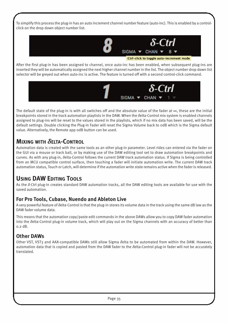
To simplify this process the plug-in has an auto increment channel number feature (auto-inc). This is enabled by a control-click on the drop down object number list.
After the first plug-in has been assigned to channel, once auto-inc has been enabled, when subsequent plug-ins areinserted they will be automatically assigned the next higher channel number in the list. The object number drop down listselector will be greyed out when auto-inc is active. The feature is turned off with a second control-click command.
The default state of the plug-in is with all switches off and the absolute value of the fader at ∞, these are the initialbreakpoints stored in the track automation playlists in the DAW. When the δelta-Control mix system is enabled channelsassigned to plug-ins will be reset to the values stored in the playlists, which if no mix data has been saved, will be thedefault settings. Double clicking the Plug-in Fader will reset the Sigma Volume back to 0dB which is the Sigma defaultvalue. Alternatively, the Remote app 0dB button can be used.
mIXING wITH δeLTA-CoNTroLAutomation data is created with the same tools as an other plug-in parameter. Level rides can entered via the fader onthe GUI via a mouse or track ball, or by making use of the DAW editing tool set to draw automation breakpoints andcurves. As with any plug-in, δelta-Control follows the current DAW track automation status. If Sigma is being controlledfrom an MCU compatible control surface, then touching a fader will initiate automation write. The current DAW trackautomation status, Touch or Latch, will determine if the automation write state remains active when the fader is released.
USING DAw eDITING TooLSAs the δ-Ctrl plug-in creates standard DAW automation tracks, all the DAW editing tools are available for use with thesaved automation.
For Pro Tools, Cubase, Nuendo and Ableton LiveA very powerful feature of δelta-Control is that the plug-in stores its volume data in the track using the same dB law as theDAW fader volume data.
This means that the automation copy/paste edit commands in the above DAWs allow you to copy DAW fader automationinto the δelta-Control plug-in volume track, which will play out on the Sigma channels with an accuracy of better than0.2 dB.
other DAwsOther VST, VST3 and AAX-compatible DAWs still allow Sigma δelta to be automated from within the DAW. However,automation data that is copied and pasted from the DAW fader to the δelta-Control plug-in fader will not be accuratelytranslated.
Page 35

7. Automating Sigma’s mix busses
The gains of Sigma’s Mix Busses can also be automated from your DAW. The Mix Bus gains are controlled using two MIDItracks outputting on ipMIDI Port 20. Please note that Mix Bus control is fixed to ipMIDI Port 20 and this has no impact onthe settings you have already established to control channel gains.
Setup Instructions1) Make sure that ipMIDI has 20 ports enable in the AudioMidi
Setup on your computer.
2) Insert two new MIDI tracks into your DAW session. Set the first to output on ipMIDI Port 20,Channel 1 and set the second to output on ipMIDI Port 20 Channel 2.
3) The first MIDI track will control Mix A master gain and the second will control Mix B master gain.
Using this method, you will be able to control Mix Bus gains, regardless of whether you areusing Delta or HUI/MCU/MIDI to automate channel gains. Both can work simultaneously.
Page 36

Appendices
APPeNDIX A – CoNNeCTorS & PINoUTS
Page 37
‘CHIP’ – Channel Input Connectors †Connector Type: 25-way D-type Female
Pin Description1 Channel 4 Right (+ve)
14 Channel 4 Right (–ve)2 0V
15 Channel 4 Left (+ve)3 Channel 4 Left (–ve)
16 0V4 Channel 3 Right (+ve)
17 Channel 3 Right (–ve)5 0V
18 Channel 3 Left (+ve)6 Channel 3 Left (–ve)
19 0V7 Channel 2 Right (+ve)
20 Channel 2 Right (–ve)8 0V
21 Channel 2 Left (+ve)9 Channel 2 Left (–ve)
22 0V10 Channel 1 Right (+ve)
23 Channel 1 Right (–ve)11 0V
24 Channel 1 Left (+ve)12 Channel 1 Left (–ve)
25 0V13 n/c
‘CHoP’ – Channel output Connectors †Connector Type: 25-way D-type Female
Pin Description1 Channel 4 Right (+ve)
14 Channel 4 Right (–ve)2 0V
15 Channel 4 Left (+ve)3 Channel 4 Left (–ve)
16 0V4 Channel 3 Right (+ve)
17 Channel 3 Right (–ve)5 0V
18 Channel 3 Left (+ve)6 Channel 3 Left (–ve)
19 0V7 Channel 2 Right (+ve)
20 Channel 2 Right (–ve)8 0V
21 Channel 2 Left (+ve)9 Channel 2 Left (–ve)
22 0V10 Channel 1 Right (+ve)
23 Channel 1 Right (–ve)11 0V
24 Channel 1 Left (+ve)12 Channel 1 Left (–ve)
25 0V13 n/c
eXT, rTNS, T/b † D-sub toXLR-F Loom
Connector Type: 25-way D-type Female
Pin Description1 n/c
XLR-814 n/c2 0V
15 Talkback Mic Input (+ve)XLR-73 Talkback Mic Input (–ve)
16 0V4 Mix B Insert Return Right (+ve)
XLR-617 Mix B Insert Return Right (–ve)5 0V
18 Mix B Insert Return Left (+ve)XLR-56 Mix B Insert Return Left (–ve)
19 0V7 Mix A Insert Return Right (+ve)
XLR-420 Mix A Insert Return Right (–ve)8 0V
21 Mix A Insert Return Left (+ve)XLR-39 Mix A Insert Return Left (–ve)
22 0V10 External Input Right (+ve)
XLR-223 External Input Right (–ve)11 0V
24 External Input Left (+ve)XLR-112 External Input Left (–ve)
25 0V13 n/c
mIX b, SeNDS, H/P † D-sub toXLR-MLoom
Connector Type: 25-way D-type Female
Pin Description1 Headphone Right (+ve, line level)
XLR-814 Headphone Right (–ve, line level)2 0V
15 Headphone Left (+ve, line level)XLR-73 Headphone Left (–ve, line level)
16 0V4 Mix B Insert Send Right (+ve)
XLR-617 Mix B Insert Send Right (–ve)5 0V
18 Mix B Insert Send Left (+ve)XLR-56 Mix B Insert Send Left (–ve)
19 0V7 Mix A Insert Send Right (+ve)
XLR-420 Mix A Insert Send Right (–ve)8 0V
21 Mix A Insert Send Left (+ve)XLR-39 Mix A Insert Send Left (–ve)
22 0V10 Mix B Output Right (+ve)
XLR-223 Mix B Output Right (–ve)11 0V
24 Mix B Output Left (+ve)XLR-112 Mix B Output Left (–ve)
25 0V13 n/c
† : D-type connector wiring follows AES59 (‘Tascam’) standard and binding posts are 4-40 UNC thread.

Appendix A – Connectors & Pinouts... Continued
main monitor outputConnector Type: XLR 3-pin Male
Pin Description1 0V (Chassis)2 Signal +ve3 Signal –ve
iJack InputConnector Type: 3.5mm Stereo Jack
DescriptionTip Signal Left
Ring Signal RightSleeve 0V (Chassis)
HeadphonesConnector Type: 0.25" Stereo Jack
DescriptionTip Signal Left
Ring Signal RightSleeve 0V (Chassis)
Alternate monitor outputConnector Type: XLR 3-pin Male
Pin Description1 0V (Chassis)2 Signal +ve3 Signal –ve
mix A outputConnector Type: XLR 3-pin Male
Pin Description1 0V (Chassis)2 Signal +ve3 Signal –ve
Foot Switch InputConnector Type: 0.25" Stereo Jack
DescriptionTip Signal
Ring 0V (Chassis)Sleeve 0V (Chassis)
Page 38

APPeNDIX b – SIGNAL FLow bLoCk DIAGrAm
Page 39

APPeNDIX C – SUPPorT
FAQsSupport information for the entire SSL range is always available through our online support site:
www.solidstatelogic.com/support
If you can’t find the answer or solution for your particular issue, questions and queries can be submitted to our supportstaff.
Page 40

required Software In order for Sigma to integrate with your DAW, ipMIDI software must be installed on your computer. Configuration of Sigmawill require the use of the Remote app.
Please login to your SSL account via the website (top right-hand side) or create a new account by clicking ‘Register’ (alsofound at the top-right of the web page).
Once registered, you will be able to sign-in and download the ipMIDI software which allows Sigma to work with your DAW.
Sigma’s Internal SoftwareThe Software Update button is used to update Sigma’s internal software. The currently installed software version is shownbelow the button. You will need to have the Ethernet cable connected to perform the update.
• Login to your SSL account here: User Loginand then select the my Products tab
• You will see a Downloads link next to yourregistered Sigma – download the Nk.binfile
• Click on the Software Update button andlocate the downloaded Nk.bin file.
• Follow the on-screen instructions to installthe update
Page 41

HardwareThe diagram below can be used in conjunction with our troubleshooting support videos for replacing Sigma’s hardware.
Rev
isio
n: 1
.0
She
et: 1
of 1
Sig
ma
Inte
rnal
Wiri
ng D
iagr
am Drg
No:
Sym
bol K
eyC
onne
ctor
Lab
el{n
ame}
Ana
logu
e A
udio
Dig
ital D
ata
6291
60X
1 - M
ain
Car
d
6291
60X
1 - C
onne
ctor
Car
d{P
L1B
}
{PL3
B}
{PL1
A}
{PL3
A}
{PL5
}
{PL7}
{SK5}{SK
7}
6261
40X
1 - C
PU
6291
61X
1 - J
ack
Car
d
{PL2B}
6291
61X
1 - D
ispl
ay C
ard
{PL2A}
Page 42
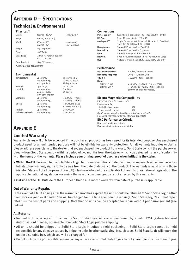
APPeNDIX D – SPeCIFICATIoNS
Technical & environmental
APPeNDIX eLimited warrantyWarranty claims will only be accepted if the purchased product has been used for its intended purpose. Any purchasedproduct used for an unintended purpose will not be eligible for warranty protection. For all warranty inquiries or claimsplease address your claim to the dealer that you purchased the product from – or to Solid State Logic if the purchase wasdirectly from Solid State Logic – within a period of two months from the date on which you detected its lack of conformitywith the terms of the warranty. Please include your original proof of purchase when initiating the claim.
• within the eU: Pursuant to the Solid State Logic Terms and Conditions under European consumer law the purchaser hasfull statutory warranty rights for two years from the date of delivery of the product. The warranty is valid only in thoseMember States of the European Union (EU) who have adopted the applicable EU law into their national legislation. Theapplicable national legislation governing the sale of consumer goods is not affected by this warranty.
• outside of the eU: Outside of the European Union a 12 month warranty from date of purchase is applicable.
out of warranty repairsIn the event of a fault arising after the warranty period has expired the unit should be returned to Solid State Logic eitherdirectly or via your local dealer. You will be charged for the time spent on the repair (at Solid State Logic's current repairrate) plus the cost of parts and shipping. Note that no units can be accepted for repair without prior arrangement (seebelow).
All returns• No unit will be accepted for repair by Solid State Logic unless accompanied by a valid RMA (Return Material
Authorisation) number, obtainable from Solid State Logic prior to shipping.• All units should be shipped to Solid State Logic in suitable rigid packaging – Solid State Logic cannot be held
responsible for any damage caused by shipping units in other packaging. In such cases Solid State Logic will return theunit in a suitable box, which you will be charged for.
• Do not include the power cable, manual or any other items – Solid State Logic can not guarantee to return them to you.
Physical *Depth 320mm / 12.75" casing only
Height 89mm / 3.5" (2 RU)
Width 435mm / 17" casing only482mm / 19" inc’ rack ears
Weight 5kg / 11 pounds
Power < 60 Watts
Boxed size 510mm x 570mm x 280mm20" x 22.5" x 11"
Boxed weight 10kg / 22 pounds
* All values are approximate
environmentalTemperature Operating: +5 to 30 deg. C
Non-operating: –20 to 50 deg. CMax. gradient: 15 deg. C/hour
Relative Operating: 20 to 80%Humidity Non-operating: 5 to 90%
Max. wet bulb: 29 deg. C(non-condensing)
Vibration Operating: < 0.2 G (3 – 100Hz)Non-operating: < 0.4 G (3 – 100Hz)
Shock Operating: < 2 G (10ms max.)Non-operating: < 10 G (10ms max.)
Altitude Operating: 0 to 3000m(above sea level) Non-operating: 0 to 12000m
ConnectionsPower Supply IEC320 3-pin connector, 100 – 240 Vac, 50 – 60 HzDC Power 2mm DC power jack, +12V, < 3AAnalogue I/o 25-pin D-type socket, balanced, Zin > 10kΩ, Zo ≈ 100Ω
3-pin XLR-M, balanced, Zo ≈ 100Ω
Headphones Stereo 1/4" jack socket, Zo ≈ 75Ω
Footswitch Stereo 1/4" jack socket (1 circuit)iJack Stereo 3.5mm jack socket, Zi ≈ 10kNetwork 8P8c modular connector; ‘RJ-45’ type (100bT, Cat5)USb 1 x type-B chassis socket (SSL diagnostic use only)
Performancemaximum I/o Level +18dBu, +22dBu or 24dBuFrequency response 20Hz – 40kHz ±0.3dBTHD + N < 0.025% (20Hz – 20kHz)Noise
CHIP to CHOP < –83dBu @ +24dBu (20Hz – 20kHz)CHIP to MIX A < –75dBu @ +24dBu (20Hz – 20kHz)
(stereo, all channels routed)
electro magnetic CompatibilityEN55103-1:2009, EN55103-2:2009Environment E4
Initial in-rush current 10A5 sec in-rush current 10A
Braid-screened cables should be used where applicableStar Quad cables should be used where applicable
emC Performance CriteriaLine level inputs and outputsMeasure at mid-gain, noise <–56dBu
Page 43
Visit SSL at: www.solidstatelogic.com
82BMSM02A© Solid State Logic
All Rights reserved under International and Pan-American Copyright Conventions
Matrix, Nucleus, SSL and Solid State Logic are trademarks of Solid State Logic
All other product names and trademarks are the property of their respective owners and are herebyacknowledged
No part of this publication may be reproduced in any form or by any means, whether mechanical orelectronic, without the written permission of Solid State Logic, Oxford, OX5 1RU, England
As research and development is a continual process, Solid State Logic reserves the right to changethe features and specifications described herein without notice or obligation.
Solid State Logic cannot be held responsible for any loss or damage arising directly or indirectlyfrom any error or omission in this manual.
E&OE
www.solidstatelogic.com