SIERRA - Free Instruction Manualsto allow enough free movement to gauge and fit the shower column....
16
SIERRA INSTALLATION AND USER GUIDE TM SQUARE SHOWER COLUMN
Transcript of SIERRA - Free Instruction Manualsto allow enough free movement to gauge and fit the shower column....
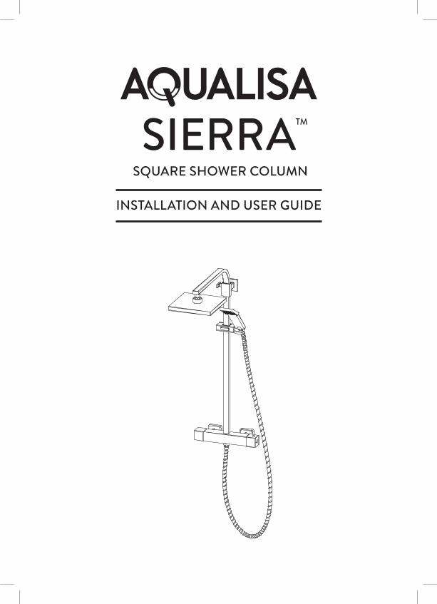
SIERRAINSTALLATION AND USER GUIDE
TM
SQUARE SHOWER COLUMN
2
GENERAL INFORMATIONThis product complies with EN1111.
This product must be fitted in compliance with the UK Water Supply (Fittings) Regulations. If in doubt please contact your local water authority.
TOOLS REQUIRED (TOOLS NOT SUPPLIED)
We have taken great care to ensure that this product reaches you in perfect condition. However should any parts be damaged or missing please contact your point of purchase. This does not affect your statutory rights. In addition if you require replacement parts please contact the Aqualisa customer helpline on 01959 560010 for assistance.
CONTENTS
General Information 2Tools Required (Tools not supplied) 2Components 3Warranty 4Before You Start 4Installation 5Cartridge Temperature Adjustment 10General Maintenance 11General Cleaning 13User Instructions 13Trouble Shooting 14
3
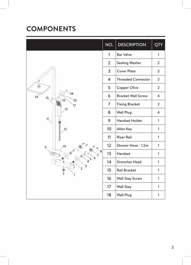
COMPONENTS
NO. DESCRIPTION QTY
1 Bar Valve 1
2 Sealing Washer 2
3 Cover Plate 2
4 Threaded Connector 2
5 Copper Olive 2
6 Bracket Wall Screw 4
7 Fixing Bracket 2
8 Wall Plug 4
9 Handset Holder 1
10 Allen Key 1
11 Riser Rail 1
12 Shower Hose - 1.5m 1
13 Handset 1
14 Drencher Head 1
15 Rail Bracket 1
16 Wall Stay Screw 1
17 Wall Stay 1
18 Wall Plug 1
1418
13
12
10
10
98
7
17
5 64
32
1
11
1615
4
WARRANTY
Aqualisa products are supplied complete with a 1 year guarantee that can be upgraded by registering this product with Aqualisa.
For details see: www.aqualisa.co.uk/warranty
BEFORE YOU START
This shower should be installed by a competent person in compliance with current Water Supply Regulations. For further details contact your Local Water Authority.a. Identify all components and check pack contents.b. Turn off water supplies.c. Suitable full bore isolation valves must be fitted to both supplies in
accordance with current Water Supply Regulations and our terms of warranty. Valves must be accessible for warranty and servicing.
Before making any pipe connections all supplies MUST be thoroughly flushed to remove any debris.
WATER SUPPLY REQUIREMENTS
Hot Water Maximum: 65˚C Cold Water Minimum: 5˚CRecommended 60-65˚C Recommended 10-15˚C
Always maintain a 10˚C difference between hot system temperature and maximum hot setting of valve.
Operating Pressure Range: Min. 1.0 bar, Max. 5.0 bar
When water pressure is higher than 5 bar a pressure reducing valve (not supplied) must be fitted before the mixer. A setting of 3 bar is recommended.
This valve is suitable for gravity boosted, balanced high pressure and combination boiler systems.
For gravity pumped systems use 22mm supply pipes and reduce to 15mm to protrude through the finished wall.
5
Pump Installation: PUMPS MUST NOT BE FITTED DIRECTLY TO A WATER MAIN. REFER TO PUMP MANUFACTURERS INSTALLATION GUIDELINES. Ensure there is adequate flow through the pump to activate the flow switches.
Combination boiler: MUST have a minimum rating of 24kW (80,000 Btu) and be of the type fitted with a fully modulating gas valve.
Boiler performance may affect outlet temperature.
Operating pressures: Hot and cold supplies should be kept as even as possible in order to ensure the maximum efficiency of the mixer.
INSTALLATIONFitting the Bar Valve
1 Ensuring adequate provision to allow the water to discharge safely to waste, turn on the supplies to flush the system through. Attach pressure test equipment and pressure test the system in accordance with Water Supply Regulations.
2 Turn off the water supply following system flushing.
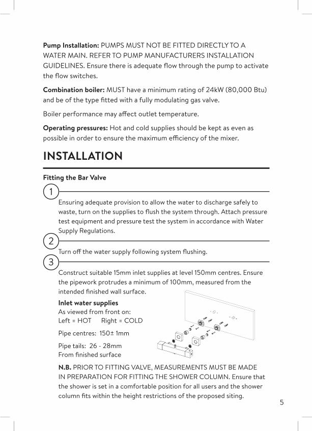
3 Construct suitable 15mm inlet supplies at level 150mm centres. Ensure the pipework protrudes a minimum of 100mm, measured from the intended finished wall surface.
N.B. PRIOR TO FITTING VALVE, MEASUREMENTS MUST BE MADE IN PREPARATION FOR FITTING THE SHOWER COLUMN. Ensure that the shower is set in a comfortable position for all users and the shower column fits within the height restrictions of the proposed siting.
Inlet water suppliesAs viewed from front on: Left = HOT Right = COLD
Pipe centres: 150± 1mm
Pipe tails: 26 - 28mm From finished surface
6
This product incorporates an adjustable height shower column.
Height adjustment: *805-1180mm
N.B. *Measured from inlet pipe centres to the top of the arm.
4 Once the wall surface has been finished, flush through the pipe work prior to trimming the length of the pipes to 26-28mm, measured from the finished wall surface.
N.B. We recommend using a rotary type cutter but if a hacksaw is used, ensure the cut is straight and the pipe ends must be carefully deburred and chamfered.
N.B. If plastic pipe is used, tube inserts must be fitted and must not increase the diameter or extend the cut off length by more than 2mm. It may be easier to fit the pipe inserts AFTER fitting the copper olives.
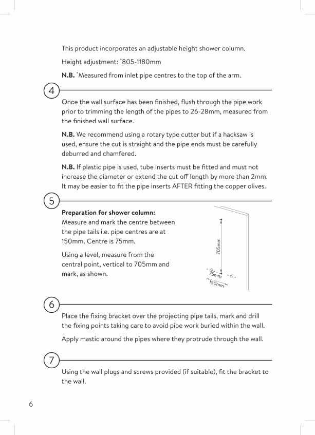
5 Preparation for shower column: Measure and mark the centre between the pipe tails i.e. pipe centres are at 150mm. Centre is 75mm.
Using a level, measure from the central point, vertical to 705mm and mark, as shown.
150mm
75mm
705m
m
6 Place the fixing bracket over the projecting pipe tails, mark and drill the fixing points taking care to avoid pipe work buried within the wall.
Apply mastic around the pipes where they protrude through the wall.
7 Using the wall plugs and screws provided (if suitable), fit the bracket to the wall.
7
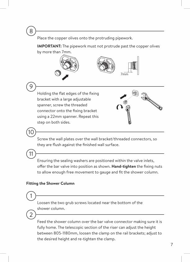
8 Place the copper olives onto the protruding pipework.
IMPORTANT: The pipework must not protrude past the copper olives by more than 7mm.
7mm
9 Holding the flat edges of the fixing bracket with a large adjustable spanner, screw the threaded connector onto the fixing bracket using a 22mm spanner. Repeat this step on both sides.
10 Screw the wall plates over the wall bracket/threaded connectors, so they are flush against the finished wall surface.
11 Ensuring the sealing washers are positioned within the valve inlets, offer the bar valve into position as shown. Hand-tighten the fixing nuts to allow enough free movement to gauge and fit the shower column.
Fitting the Shower Column
1 Loosen the two grub screws located near the bottom of the shower column.
2 Feed the shower column over the bar valve connector making sure it is fully home. The telescopic section of the riser can adjust the height between 805-1180mm, loosen the clamp on the rail brackets; adjust to the desired height and re-tighten the clamp.
8
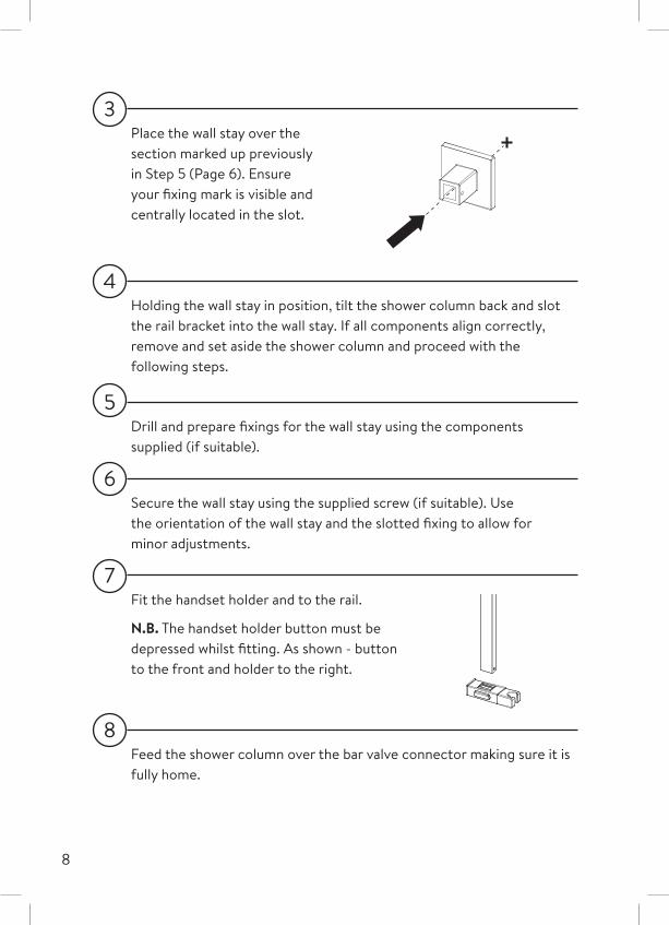
3 Place the wall stay over the section marked up previously in Step 5 (Page 6). Ensure your fixing mark is visible and centrally located in the slot.
4 Holding the wall stay in position, tilt the shower column back and slot the rail bracket into the wall stay. If all components align correctly, remove and set aside the shower column and proceed with the following steps.
5 Drill and prepare fixings for the wall stay using the components supplied (if suitable).
6 Secure the wall stay using the supplied screw (if suitable). Use the orientation of the wall stay and the slotted fixing to allow for minor adjustments.
7 Fit the handset holder and to the rail.
N.B. The handset holder button must be depressed whilst fitting. As shown - button to the front and holder to the right.
8 Feed the shower column over the bar valve connector making sure it is fully home.
9
9 Tilt the shower column back and slot the rail bracket into the wall stay, hold in place by gently tightening the grub screws (final adjustment will be made in step 10).
10 Tighten the bar valve fixing nuts using a suitable tool, taking care not to overtighten and adjust the rail bracket to ensure the shower column is level, tighten grub screws to secure.
11 Turn on water supplies and check for leaks.
12 Ensuring the hose washer is in position; attach the non-conical end of the hose to the bar valve. Run the shower for a few seconds to clear any debris that may be present.
13 Pass the conical end of the shower hose through the hose restraint.
14 Ensuring the hose washer is in position; attach the conical end of the hose to the shower head, then place the hose in the handset holder.
15 Fitting drencher head: Ensure the washer is in place, screw the drencher head onto the arm, taking care not to damage the plated surface. Tighten carefully using a suitable tool taking care not to overtighten.
10
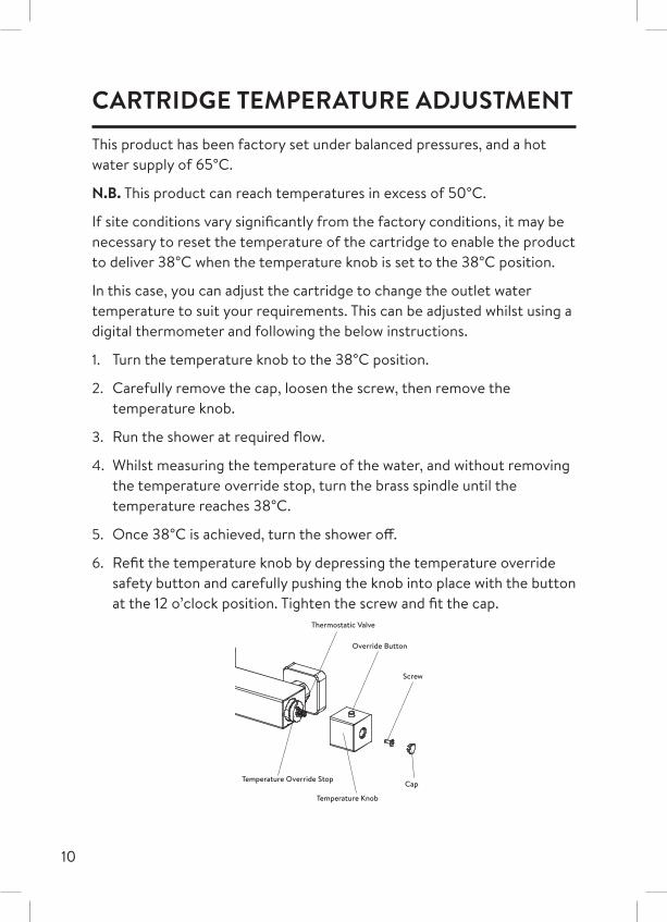
CARTRIDGE TEMPERATURE ADJUSTMENTThis product has been factory set under balanced pressures, and a hot water supply of 65°C.
N.B. This product can reach temperatures in excess of 50°C.
If site conditions vary significantly from the factory conditions, it may be necessary to reset the temperature of the cartridge to enable the product to deliver 38°C when the temperature knob is set to the 38°C position.
In this case, you can adjust the cartridge to change the outlet water temperature to suit your requirements. This can be adjusted whilst using a digital thermometer and following the below instructions.
1. Turn the temperature knob to the 38°C position.
2. Carefully remove the cap, loosen the screw, then remove the temperature knob.
3. Run the shower at required flow.
4. Whilst measuring the temperature of the water, and without removing the temperature override stop, turn the brass spindle until the temperature reaches 38°C.
5. Once 38°C is achieved, turn the shower off.
6. Refit the temperature knob by depressing the temperature override safety button and carefully pushing the knob into place with the button at the 12 o’clock position. Tighten the screw and fit the cap.
Cap
Screw
Override Button
Temperature Knob
Temperature Override Stop
Thermostatic Valve
11
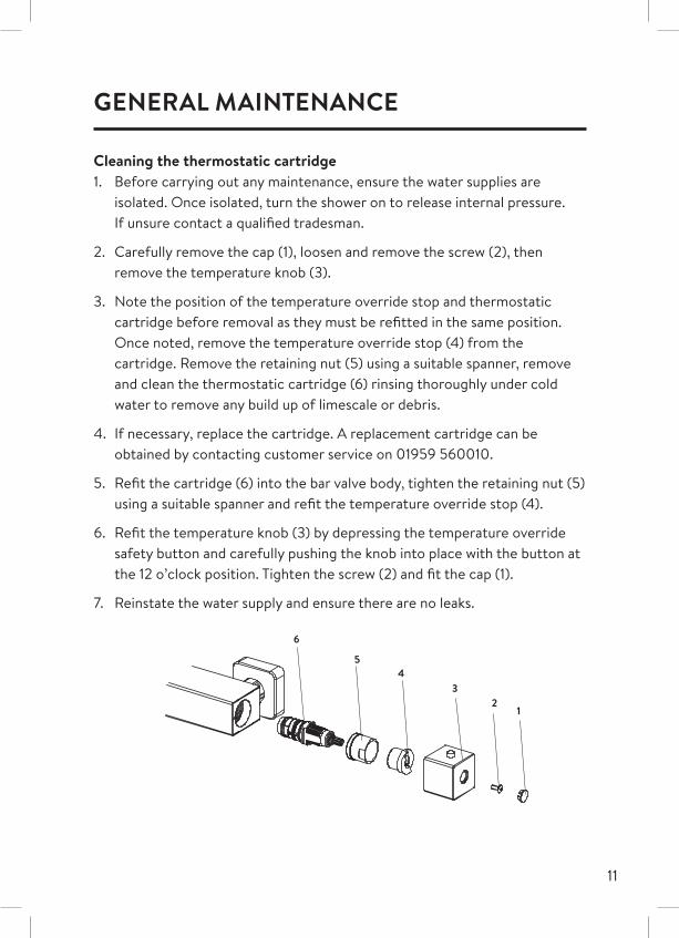
GENERAL MAINTENANCE
Cleaning the thermostatic cartridge1. Before carrying out any maintenance, ensure the water supplies are
isolated. Once isolated, turn the shower on to release internal pressure. If unsure contact a qualified tradesman.
2. Carefully remove the cap (1), loosen and remove the screw (2), then remove the temperature knob (3).
3. Note the position of the temperature override stop and thermostatic cartridge before removal as they must be refitted in the same position. Once noted, remove the temperature override stop (4) from the cartridge. Remove the retaining nut (5) using a suitable spanner, remove and clean the thermostatic cartridge (6) rinsing thoroughly under cold water to remove any build up of limescale or debris.
4. If necessary, replace the cartridge. A replacement cartridge can be obtained by contacting customer service on 01959 560010.
5. Refit the cartridge (6) into the bar valve body, tighten the retaining nut (5) using a suitable spanner and refit the temperature override stop (4).
6. Refit the temperature knob (3) by depressing the temperature override safety button and carefully pushing the knob into place with the button at the 12 o’clock position. Tighten the screw (2) and fit the cap (1).
7. Reinstate the water supply and ensure there are no leaks.
12
34
5
6
12
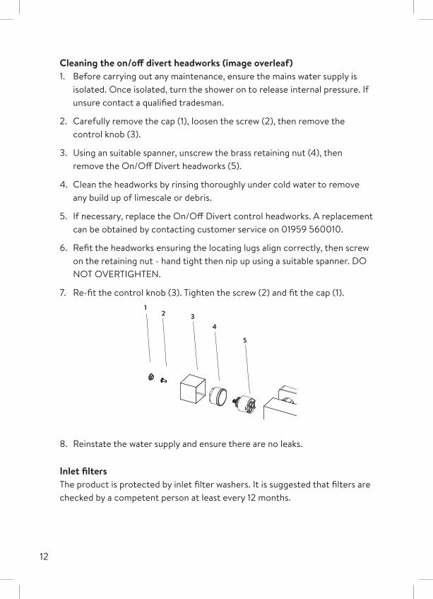
Cleaning the on/off divert headworks (image overleaf)1. Before carrying out any maintenance, ensure the mains water supply is
isolated. Once isolated, turn the shower on to release internal pressure. If unsure contact a qualified tradesman.
2. Carefully remove the cap (1), loosen the screw (2), then remove the control knob (3).
3. Using an suitable spanner, unscrew the brass retaining nut (4), then remove the On/Off Divert headworks (5).
4. Clean the headworks by rinsing thoroughly under cold water to remove any build up of limescale or debris.
5. If necessary, replace the On/Off Divert control headworks. A replacement can be obtained by contacting customer service on 01959 560010.
6. Refit the headworks ensuring the locating lugs align correctly, then screw on the retaining nut - hand tight then nip up using a suitable spanner. DO NOT OVERTIGHTEN.
7. Re-fit the control knob (3). Tighten the screw (2) and fit the cap (1).
4
5
12 3
8. Reinstate the water supply and ensure there are no leaks.
Inlet filtersThe product is protected by inlet filter washers. It is suggested that filters are checked by a competent person at least every 12 months.
13
GENERAL CLEANINGWhilst modern plating techniques are used in the manufacture of these fittings, the plating will wear if not cleaned properly. The safest way to clean your product is to wipe with a soft damp cloth. Stains can be removed using washing up liquid.
DO NOT USE ABRASIVE CLEANERS.
LimescaleRub the nozzles of the shower head to break down scale build up. Should chemical descaling of the head become necessary, remove the shower head fully and immerse in a mild proprietary descaler.
IT IS IMPERATIVE THAT DESCALING IS CARRIED OUT STRICTLY IN ACCORDANCE WITH THE MANUFACTURERS INSTRUCTIONS. SUBSTANCES THAT ARE NOT SUITABLE FOR PLASTICS AND ELECTROPLATED SURFACES MUST NOT BE USED.
USER INSTRUCTIONS
Shower valve - The bar valve and fixing bracket assembly MUST NOT be used as a grab rail or means of support.
Controls - As viewed from the front: On/Off Divert - Left Temperature - RightTo turn on the drencher head rotate the left hand control knob towards the wall.
To turn on the handset rotate the left hand control knob away from the wall.
Turn the shower off by bringing the control knob back to the central position.
The shower is at mid-blend position when the button on the right hand knob is centrally at the top.
N.B. The mid blend temperature is dictated by the temperature of the incoming supplies.
14
To select a comfortable showering temperature, depress the override button and rotate the dial using the temperature markings as a guide.
For cooler temperature - rotate towards the wall.
For warmer temperature - rotate away from the wall.
N.B. With all Sierra shower valves fitted to combination boiler systems, it may be necessary to adjust the flow control knob and reduce the flow to achieve a comfortable showering temperature. Shower head
1. To select the preferred height of the handset, depress the handset holder button to enable the slider to be moved up or down the rail.
2. Angular adjustment is made by carefully but firmly pulling the shower head forwards, or pushing the shower head back towards the wall.
N.B. The tension of the handset holder can be adjusted with a screwdriver.
3. The height of the shower column can be adjusted, refer to Page 7, section 2.
NEVER ATTEMPT TO MAKE ANY ADJUSTMENT TO THE SHOWER HEAD BY PULLING ON THE SHOWER HOSE.
TROUBLE SHOOTING
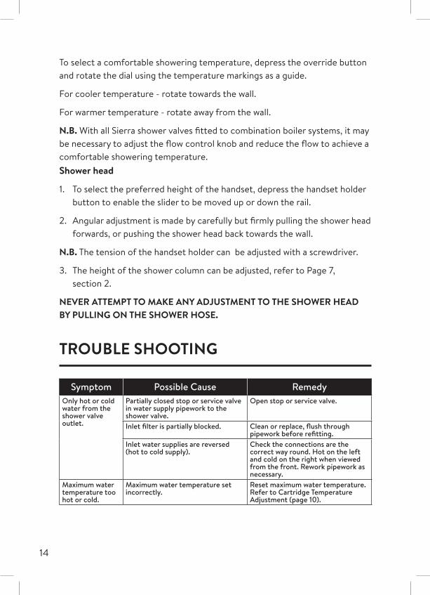
Symptom Possible Cause RemedyOnly hot or cold water from the shower valve outlet.
Partially closed stop or service valve in water supply pipework to the shower valve.
Open stop or service valve.
Inlet filter is partially blocked. Clean or replace, flush through pipework before refitting.
Inlet water supplies are reversed (hot to cold supply).
Check the connections are the correct way round. Hot on the left and cold on the right when viewed from the front. Rework pipework as necessary.
Maximum water temperature too hot or cold.
Maximum water temperature set incorrectly.
Reset maximum water temperature. Refer to Cartridge Temperature Adjustment (page 10).
15
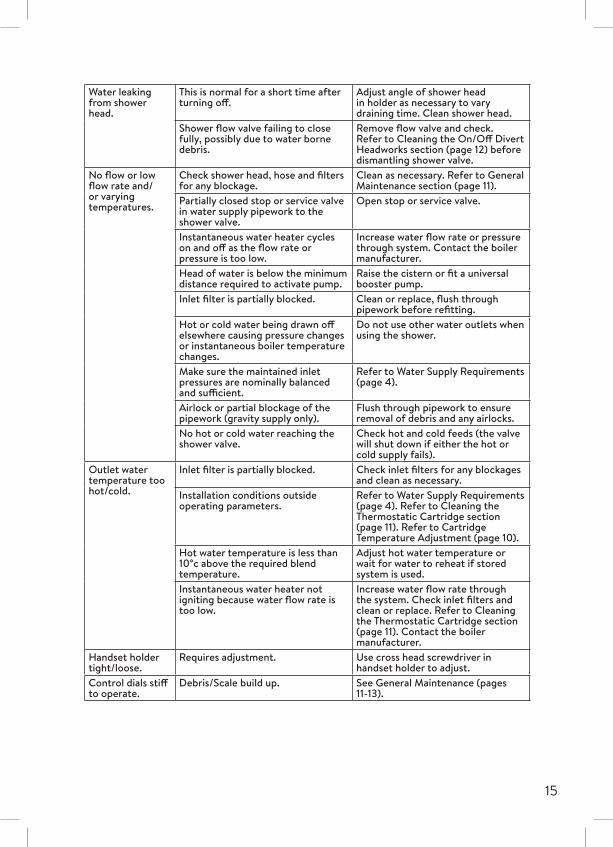
Water leaking from shower head.
This is normal for a short time after turning off.
Adjust angle of shower head in holder as necessary to vary draining time. Clean shower head.
Shower flow valve failing to close fully, possibly due to water borne debris.
Remove flow valve and check.Refer to Cleaning the On/Off Divert Headworks section (page 12) before dismantling shower valve.
No flow or low flow rate and/or varying temperatures.
Check shower head, hose and filters for any blockage.
Clean as necessary. Refer to General Maintenance section (page 11).
Partially closed stop or service valve in water supply pipework to the shower valve.
Open stop or service valve.
Instantaneous water heater cycles on and off as the flow rate or pressure is too low.
Increase water flow rate or pressure through system. Contact the boiler manufacturer.
Head of water is below the minimum distance required to activate pump.
Raise the cistern or fit a universal booster pump.
Inlet filter is partially blocked. Clean or replace, flush through pipework before refitting.
Hot or cold water being drawn off elsewhere causing pressure changes or instantaneous boiler temperature changes.
Do not use other water outlets when using the shower.
Make sure the maintained inlet pressures are nominally balanced and sufficient.
Refer to Water Supply Requirements (page 4).
Airlock or partial blockage of the pipework (gravity supply only).
Flush through pipework to ensure removal of debris and any airlocks.
No hot or cold water reaching the shower valve.
Check hot and cold feeds (the valve will shut down if either the hot or cold supply fails).
Outlet water temperature too hot/cold.
Inlet filter is partially blocked. Check inlet filters for any blockages and clean as necessary.
Installation conditions outside operating parameters.
Refer to Water Supply Requirements (page 4). Refer to Cleaning the Thermostatic Cartridge section (page 11). Refer to Cartridge Temperature Adjustment (page 10).
Hot water temperature is less than 10°c above the required blend temperature.
Adjust hot water temperature or wait for water to reheat if stored system is used.
Instantaneous water heater not igniting because water flow rate is too low.
Increase water flow rate through the system. Check inlet filters and clean or replace. Refer to Cleaning the Thermostatic Cartridge section (page 11). Contact the boiler manufacturer.
Handset holder tight/loose.
Requires adjustment. Use cross head screwdriver in handset holder to adjust.
Control dials stiff to operate.
Debris/Scale build up. See General Maintenance (pages 11-13).
Aqualisa Products LimitedThe Flyers WayWesterham Kent TN16 1DE
Customer Helpline: 01959 560010 | Brochure Hotline: 0800 652 3669 Website: www.aqualisa.co.uk | Email: [email protected]: www.aqualisa.co.uk/warranty
Republic of IrelandSales enquiries: 01-864-3363Service enquiries: 01-844-3212
Part No: 704450 Issue 02 July 19
Please note that calls may be recorded for training and quality purposes.
The company reserves the right to alter, change or modify the product specifications without prior warning.
™ Trademark of Aqualisa Products Limited.