Siemens UMR50 Rncomnf
383
UTRAN Operation Radio Network Controller OMN:RNC Radio Network Configuration - Basics A50016-G5000-G176-2-7619 ND-57508-702(E)-02
-
Upload
mykeenzo5658 -
Category
Documents
-
view
50 -
download
1
description
Siemens
Transcript of Siemens UMR50 Rncomnf

UTRAN
Operation
Radio Network Controller
OMN:RNC Radio Network Configuration -Basics
A50016-G5000-G176-2-7619ND-57508-702(E)-02

2Siemens AG:A50016-G5000-G176-2-7619NEC Corporation:ND-57508-702(E)-02
OMN:RNC Radio Network Configuration -Basics
OperationRadio Network Controller
f Important Notice on Product Safety
DANGER - RISK OF ELECTRICAL SHOCK OR DEATH - FOLLOW ALL INSTALLATION INSTRUCTIONS.
The system complies with the standard EN 60950 / IEC 60950. All equipment connected to the system mustcomply with the applicable safety standards.Hazardous voltages are present at the AC power supply lines in this electrical equipment. Some components mayalso have high operating temperatures.Failure to observe and follow all installation and safety instructions can result in serious personal injuryor property damage.Therefore, only trained and qualified personnel may install and maintain the system.
The same text in German:
Wichtiger Hinweis zur Produktsicherheit
LEBENSGEFAHR - BEACHTEN SIE ALLE INSTALLATIONSHINWEISE.
Das System entspricht den Anforderungen der EN 60950 / IEC 60950. Alle an das System angeschlossenenGeräte müssen die zutreffenden Sicherheitsbestimmungen erfüllen.In diesen Anlagen stehen die Netzversorgungsleitungen unter gefährlicher Spannung. Einige Komponentenkönnen auch eine hohe Betriebstemperatur aufweisen.Nichtbeachtung der Installations- und Sicherheitshinweise kann zu schweren Körperverletzungen oderSachschäden führen.Deshalb darf nur geschultes und qualifiziertes Personal das System installieren und warten.
Caution:This equipment has been tested and found to comply with EN 301489. Its class of conformity is defined in tableA30808-X3247-X910-*-7618, which is shipped with each product. This class also corresponds to the limits for aClass A digital device, pursuant to part 15 of the FCC Rules.These limits are designed to provide reasonable protection against harmful interference when the equipment isoperated in a commercial environment.This equipment generates, uses and can radiate radio frequency energy and, if not installed and used in accor-dance with the relevant standards referenced in the manual “Guide to Documentation”, may cause harmful inter-ference to radio communications.For system installations it is strictly required to choose all installation sites according to national and local require-ments concerning construction rules and static load capacities of buildings and roofs.For all sites, in particular in residential areas it is mandatory to observe all respectively applicable electromagneticfield / force (EMF) limits. Otherwise harmful personal interference is possible.
Trademarks:
All designations used in this document can be trademarks, the use of which by third parties for their own purposescould violate the rights of their owners.
Copyright (C) Siemens AG / NEC Corporation 2005-2006.
Issued by:Siemens AG, Communications, Hofmannstrasse 51, 81359 München, Germany andNEC Corporation, 7-1, Shiba 5-chome, Minato-ku, Tokyo, Japan
Technical modifications possible.Technical specifications and features are binding only insofar as they are specifically and expressly agreed upon in a written contract.
OperationRadio Network Controller
OMN:RNC Radio Network Configuration -Basics
Siemens AG: A50016-G5000-G176-2-7619NEC Corporation: ND-57508-702(E)-02 3
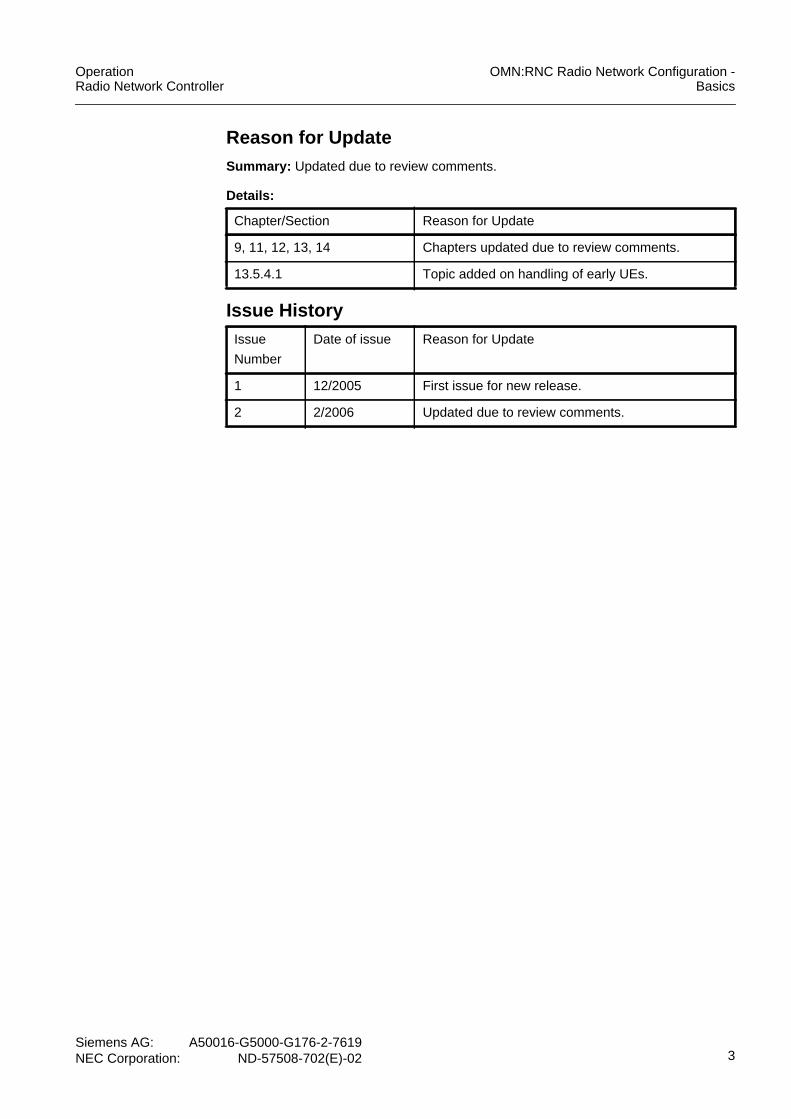
Reason for UpdateSummary: Updated due to review comments.
Details:
Chapter/Section Reason for Update
9, 11, 12, 13, 14 Chapters updated due to review comments.
13.5.4.1 Topic added on handling of early UEs.
Issue HistoryIssue
Number
Date of issue Reason for Update
1 12/2005 First issue for new release.
2 2/2006 Updated due to review comments.
OMN:RNC Radio Network Configuration -Basics
OperationRadio Network Controller
4Siemens AG:A50016-G5000-G176-2-7619NEC Corporation:ND-57508-702(E)-02
This document consists of 383 pages. All pages are issue 2.
Contents
1 Introduction . . . . . . . . . . . . . . . . . . . . . . . . . . . . . . . . . . . . . . . . . . . . . . . . . 161.1 Characteristics of UTRAN Cells . . . . . . . . . . . . . . . . . . . . . . . . . . . . . . . . . . 181.2 Radio Resource Management Functions. . . . . . . . . . . . . . . . . . . . . . . . . . . 19
2 UTRAN Cell . . . . . . . . . . . . . . . . . . . . . . . . . . . . . . . . . . . . . . . . . . . . . . . . . 222.1 Adjacent Cells . . . . . . . . . . . . . . . . . . . . . . . . . . . . . . . . . . . . . . . . . . . . . . . 272.1.1 Adjacent Cell List . . . . . . . . . . . . . . . . . . . . . . . . . . . . . . . . . . . . . . . . . . . . . 302.1.2 Cell Individual Offset . . . . . . . . . . . . . . . . . . . . . . . . . . . . . . . . . . . . . . . . . . 31
3 Hierarchical Cell Structures . . . . . . . . . . . . . . . . . . . . . . . . . . . . . . . . . . . . . 353.1 Hierarchical Cell Structure Scenarios . . . . . . . . . . . . . . . . . . . . . . . . . . . . . 37
4 Geographical Coordinates of a Cell . . . . . . . . . . . . . . . . . . . . . . . . . . . . . . . 39
5 Area Concepts . . . . . . . . . . . . . . . . . . . . . . . . . . . . . . . . . . . . . . . . . . . . . . . 405.1 Location Areas and Routing Areas . . . . . . . . . . . . . . . . . . . . . . . . . . . . . . . 415.2 Location Area Update and Routing Area Update. . . . . . . . . . . . . . . . . . . . . 435.3 UE Service States and RRC Connection States . . . . . . . . . . . . . . . . . . . . . 445.4 Paging . . . . . . . . . . . . . . . . . . . . . . . . . . . . . . . . . . . . . . . . . . . . . . . . . . . . . 455.5 Handling of the PLMN Value Tag. . . . . . . . . . . . . . . . . . . . . . . . . . . . . . . . . 455.6 Location Services. . . . . . . . . . . . . . . . . . . . . . . . . . . . . . . . . . . . . . . . . . . . . 46
6 Common Channel-Related Information . . . . . . . . . . . . . . . . . . . . . . . . . . . . 476.1 Mapping of Transport Channels to Physical Channels . . . . . . . . . . . . . . . . 486.2 Iub-related Common Channel Information . . . . . . . . . . . . . . . . . . . . . . . . . . 516.3 Downlink Common Transport Channel . . . . . . . . . . . . . . . . . . . . . . . . . . . . 526.3.1 Downlink Common Channel Control . . . . . . . . . . . . . . . . . . . . . . . . . . . . . . 526.3.2 High-Speed Downlink Packet Access Channel . . . . . . . . . . . . . . . . . . . . . . 536.4 Uplink Common Transport Channel. . . . . . . . . . . . . . . . . . . . . . . . . . . . . . . 54
7 Radio Bearer Translation . . . . . . . . . . . . . . . . . . . . . . . . . . . . . . . . . . . . . . . 557.1 Basic Mechanism for Radio Bearer Translation. . . . . . . . . . . . . . . . . . . . . . 577.2 Mapping Models. . . . . . . . . . . . . . . . . . . . . . . . . . . . . . . . . . . . . . . . . . . . . . 617.3 Mapping Procedures . . . . . . . . . . . . . . . . . . . . . . . . . . . . . . . . . . . . . . . . . . 637.3.1 RRC Connection Setup . . . . . . . . . . . . . . . . . . . . . . . . . . . . . . . . . . . . . . . . 657.3.2 CS Bearer Setup . . . . . . . . . . . . . . . . . . . . . . . . . . . . . . . . . . . . . . . . . . . . . 667.3.2.1 Addition of a CS Bearer to a PS Bearer. . . . . . . . . . . . . . . . . . . . . . . . . . . . 677.3.3 PS Bearer Setup . . . . . . . . . . . . . . . . . . . . . . . . . . . . . . . . . . . . . . . . . . . . . 687.3.3.1 Addition of a PS Streaming/Conversational Bearer to a PS I/B Bearer . . . . 697.3.4 CS Bearer Release . . . . . . . . . . . . . . . . . . . . . . . . . . . . . . . . . . . . . . . . . . . 707.3.5 PS Bearer Release . . . . . . . . . . . . . . . . . . . . . . . . . . . . . . . . . . . . . . . . . . . 707.3.5.1 Release of a PS Streaming/Conversational Bearer
if a PS I/B Bearer Remains . . . . . . . . . . . . . . . . . . . . . . . . . . . . . . . . . . . . . 717.3.6 Release of the Last Bearer . . . . . . . . . . . . . . . . . . . . . . . . . . . . . . . . . . . . . 717.3.7 Mapping Procedures for HSDPA . . . . . . . . . . . . . . . . . . . . . . . . . . . . . . . . . 71
8 Radio Bearer Control . . . . . . . . . . . . . . . . . . . . . . . . . . . . . . . . . . . . . . . . . . 758.1 Bearer Services . . . . . . . . . . . . . . . . . . . . . . . . . . . . . . . . . . . . . . . . . . . . . . 78

OperationRadio Network Controller
OMN:RNC Radio Network Configuration -Basics
Siemens AG: A50016-G5000-G176-2-7619NEC Corporation: ND-57508-702(E)-02 5
8.1.1 RAB Services for User Plane Traffic. . . . . . . . . . . . . . . . . . . . . . . . . . . . . . 798.1.2 Bearers for Control Plane Traffic (Signaling Radio Bearers) . . . . . . . . . . . 838.2 Iu Quality of Service Mechanism . . . . . . . . . . . . . . . . . . . . . . . . . . . . . . . . 838.3 Data Rate Management . . . . . . . . . . . . . . . . . . . . . . . . . . . . . . . . . . . . . . . 848.3.1 State Management . . . . . . . . . . . . . . . . . . . . . . . . . . . . . . . . . . . . . . . . . . . 878.3.1.1 Radio Resource Control Connection States . . . . . . . . . . . . . . . . . . . . . . . . 888.3.1.2 Internal RNC States . . . . . . . . . . . . . . . . . . . . . . . . . . . . . . . . . . . . . . . . . . 908.3.1.3 RRC Connection States for HSDPA . . . . . . . . . . . . . . . . . . . . . . . . . . . . . . 938.3.2 Transport-Channel-Type Switching . . . . . . . . . . . . . . . . . . . . . . . . . . . . . . 948.3.2.1 Switching Between Cell_FACH and Cell DCH state. . . . . . . . . . . . . . . . . . 968.3.2.2 Switching between Cell_FACH and Cell_PCH/URA_PCH . . . . . . . . . . . . . 978.3.2.3 Switching between Cell_PCH/URA_PCH and Idle mode . . . . . . . . . . . . . . 988.3.3 Bit Rate Adaptation . . . . . . . . . . . . . . . . . . . . . . . . . . . . . . . . . . . . . . . . . . . 988.3.3.1 Evaluation of the UL Radio Link Quality . . . . . . . . . . . . . . . . . . . . . . . . . . 1008.3.3.2 Evaluation of the DL Radio Link Quality . . . . . . . . . . . . . . . . . . . . . . . . . . 1008.3.3.3 Resource Demand Evaluation Based on Traffic Measurement . . . . . . . . 1048.3.3.4 Data Rate Change . . . . . . . . . . . . . . . . . . . . . . . . . . . . . . . . . . . . . . . . . . 1098.3.3.5 Node B Dedicated Measurements for Bit Rate Adaptation. . . . . . . . . . . . 1128.3.4 Data Rate Management for PS I/B RABs . . . . . . . . . . . . . . . . . . . . . . . . . 1148.3.4.1 Handling of Early UEs. . . . . . . . . . . . . . . . . . . . . . . . . . . . . . . . . . . . . . . . 1178.3.5 Data Rate Management for HSDPA . . . . . . . . . . . . . . . . . . . . . . . . . . . . . 1208.3.6 Load-Based Bit Rate Adaptation. . . . . . . . . . . . . . . . . . . . . . . . . . . . . . . . 1218.4 RRC Connection and RAB Establishment on Common Channels . . . . . . 1248.5 SMS Cell Broadcast Service. . . . . . . . . . . . . . . . . . . . . . . . . . . . . . . . . . . 1268.6 HSDPA RAB Handling . . . . . . . . . . . . . . . . . . . . . . . . . . . . . . . . . . . . . . . 130
9 Higher Layer Filtering . . . . . . . . . . . . . . . . . . . . . . . . . . . . . . . . . . . . . . . . 133
10 Power Control . . . . . . . . . . . . . . . . . . . . . . . . . . . . . . . . . . . . . . . . . . . . . . 13510.1 Basic Mechanism of Power Control . . . . . . . . . . . . . . . . . . . . . . . . . . . . . 13810.1.1 Radio Link Setup and Power Control . . . . . . . . . . . . . . . . . . . . . . . . . . . . 13910.2 Open Loop Power Control . . . . . . . . . . . . . . . . . . . . . . . . . . . . . . . . . . . . 14010.2.1 RACH Tx Power . . . . . . . . . . . . . . . . . . . . . . . . . . . . . . . . . . . . . . . . . . . . 14010.2.2 UL DPCCH Initial Power . . . . . . . . . . . . . . . . . . . . . . . . . . . . . . . . . . . . . . 14210.2.3 DL DPCCH Initial Power . . . . . . . . . . . . . . . . . . . . . . . . . . . . . . . . . . . . . . 14310.2.4 Basic Concept to Calculate the Initial Values for Power Control . . . . . . . 14510.2.4.1 Parameters Calculated in the SRNC . . . . . . . . . . . . . . . . . . . . . . . . . . . . 14510.2.4.2 Parameters Calculated in the CRNC/DRNC. . . . . . . . . . . . . . . . . . . . . . . 14610.3 Closed Loop Power Control . . . . . . . . . . . . . . . . . . . . . . . . . . . . . . . . . . . 14710.3.1 Inner Loop Power Control . . . . . . . . . . . . . . . . . . . . . . . . . . . . . . . . . . . . . 14810.3.1.1 UL DPCCH/DPDCH Tx Power Setting . . . . . . . . . . . . . . . . . . . . . . . . . . . 14910.3.1.2 DL DPCH Tx Power Setting . . . . . . . . . . . . . . . . . . . . . . . . . . . . . . . . . . . 15210.3.2 Outer Loop Power Control (OLPC) . . . . . . . . . . . . . . . . . . . . . . . . . . . . . . 15510.3.2.1 Basic Concept of Outer Loop Power Control . . . . . . . . . . . . . . . . . . . . . . 15710.3.2.2 Basic Mechanism of Uplink Outer Loop Power Control . . . . . . . . . . . . . . 15810.4 Power Balancing . . . . . . . . . . . . . . . . . . . . . . . . . . . . . . . . . . . . . . . . . . . . 16610.4.1 Power Balancing Algorithm. . . . . . . . . . . . . . . . . . . . . . . . . . . . . . . . . . . . 16710.4.2 Procedure Activation. . . . . . . . . . . . . . . . . . . . . . . . . . . . . . . . . . . . . . . . . 170

OMN:RNC Radio Network Configuration -Basics
OperationRadio Network Controller
6Siemens AG:A50016-G5000-G176-2-7619NEC Corporation:ND-57508-702(E)-02
10.4.3 Update of the DL Reference Power PREF . . . . . . . . . . . . . . . . . . . . . . . . . 17110.4.4 Feature Control over the Iur Interface . . . . . . . . . . . . . . . . . . . . . . . . . . . . 172
11 Admission Control . . . . . . . . . . . . . . . . . . . . . . . . . . . . . . . . . . . . . . . . . . . 17311.1 Admission Control and Load Calculation . . . . . . . . . . . . . . . . . . . . . . . . . . 17511.1.1 Load Thresholds . . . . . . . . . . . . . . . . . . . . . . . . . . . . . . . . . . . . . . . . . . . . 17711.1.2 Calculation of the Load for a New Bearer . . . . . . . . . . . . . . . . . . . . . . . . . 17911.2 Interdependencies of Admission Control and Congestion Control. . . . . . . 18011.3 SRNC/DRNC - CRNC Interface . . . . . . . . . . . . . . . . . . . . . . . . . . . . . . . . . 18111.4 Basic Algorithm of Admission Control . . . . . . . . . . . . . . . . . . . . . . . . . . . . 18211.4.1 Uplink Call Admission Procedure. . . . . . . . . . . . . . . . . . . . . . . . . . . . . . . . 18811.4.2 Downlink Call Admission Procedure . . . . . . . . . . . . . . . . . . . . . . . . . . . . . 19211.4.3 Higher Layer Filtering. . . . . . . . . . . . . . . . . . . . . . . . . . . . . . . . . . . . . . . . . 19411.5 Admission Control for PS Interactive/Background RABs. . . . . . . . . . . . . . 19411.6 Handling of Emergency Calls. . . . . . . . . . . . . . . . . . . . . . . . . . . . . . . . . . . 19511.7 Admission Control for HSDPA . . . . . . . . . . . . . . . . . . . . . . . . . . . . . . . . . . 19611.8 Restriction Control . . . . . . . . . . . . . . . . . . . . . . . . . . . . . . . . . . . . . . . . . . . 19611.8.1 Restriction Control Mechanism . . . . . . . . . . . . . . . . . . . . . . . . . . . . . . . . . 19911.8.2 Restriction Control in the CRNC for HSDPA . . . . . . . . . . . . . . . . . . . . . . . 20111.9 Admission Control in the Node B . . . . . . . . . . . . . . . . . . . . . . . . . . . . . . . . 20211.9.1 Admission Control in the Node B . . . . . . . . . . . . . . . . . . . . . . . . . . . . . . . . 20411.10 Pre-Emption . . . . . . . . . . . . . . . . . . . . . . . . . . . . . . . . . . . . . . . . . . . . . . . . 20411.10.1 RNC-Based Radio Link Pre-Emption . . . . . . . . . . . . . . . . . . . . . . . . . . . . . 20511.10.1.1SRNC Setting of the DCH Allocation/Retention Priority. . . . . . . . . . . . . . . 20611.10.1.2DRNC Handling of the DCH Allocation/Retention Priority . . . . . . . . . . . . . 20711.10.1.3SRNC/DRNC Mapping of the DCH to the
Radio Link Allocation/Retention Priority . . . . . . . . . . . . . . . . . . . . . . . . . . . 20711.10.1.4CRNC Radio Link Pre-Emption . . . . . . . . . . . . . . . . . . . . . . . . . . . . . . . . . 20811.10.1.5Release of Resources . . . . . . . . . . . . . . . . . . . . . . . . . . . . . . . . . . . . . . . . 21011.10.1.6Establishment of Resources . . . . . . . . . . . . . . . . . . . . . . . . . . . . . . . . . . . 21211.10.1.7Parallel Pre-Emption Procedures. . . . . . . . . . . . . . . . . . . . . . . . . . . . . . . . 21211.10.1.8Radio Link Pre-Emption Failure . . . . . . . . . . . . . . . . . . . . . . . . . . . . . . . . . 21211.10.2 Pre-Emption for HSDPA. . . . . . . . . . . . . . . . . . . . . . . . . . . . . . . . . . . . . . . 21211.11 Scrambling and Channelization Codes . . . . . . . . . . . . . . . . . . . . . . . . . . . 21311.11.1 Code and Power Allocation for HSDPA . . . . . . . . . . . . . . . . . . . . . . . . . . . 214
12 Congestion Control . . . . . . . . . . . . . . . . . . . . . . . . . . . . . . . . . . . . . . . . . . 21912.1 Basic Concept of Congestion Control . . . . . . . . . . . . . . . . . . . . . . . . . . . . 22012.1.1 Congestion Decision . . . . . . . . . . . . . . . . . . . . . . . . . . . . . . . . . . . . . . . . . 22312.1.1.1 Thresholds 1 and 2 (UL) . . . . . . . . . . . . . . . . . . . . . . . . . . . . . . . . . . . . . . 22412.1.1.2 Thresholds 1 and 2 (DL) . . . . . . . . . . . . . . . . . . . . . . . . . . . . . . . . . . . . . . 22412.1.1.3 Congestion Threshold Update . . . . . . . . . . . . . . . . . . . . . . . . . . . . . . . . . . 22412.1.1.4 Handling of Lost Events . . . . . . . . . . . . . . . . . . . . . . . . . . . . . . . . . . . . . . . 22512.1.1.5 Higher Layer Filtering. . . . . . . . . . . . . . . . . . . . . . . . . . . . . . . . . . . . . . . . . 22612.1.2 Congestion Handling . . . . . . . . . . . . . . . . . . . . . . . . . . . . . . . . . . . . . . . . . 22712.1.2.1 Stage 1. . . . . . . . . . . . . . . . . . . . . . . . . . . . . . . . . . . . . . . . . . . . . . . . . . . . 22812.1.2.2 Stage 2. . . . . . . . . . . . . . . . . . . . . . . . . . . . . . . . . . . . . . . . . . . . . . . . . . . . 23012.2 Congestion Control and Pre-Emption . . . . . . . . . . . . . . . . . . . . . . . . . . . . 230

OperationRadio Network Controller
OMN:RNC Radio Network Configuration -Basics
Siemens AG: A50016-G5000-G176-2-7619NEC Corporation: ND-57508-702(E)-02 7
12.3 Congestion Control Algorithm for HSDPA . . . . . . . . . . . . . . . . . . . . . . . . 231
13 Handover Control . . . . . . . . . . . . . . . . . . . . . . . . . . . . . . . . . . . . . . . . . . . 23213.1 Handover Functions in UMTS. . . . . . . . . . . . . . . . . . . . . . . . . . . . . . . . . . 23513.2 Measurement Control . . . . . . . . . . . . . . . . . . . . . . . . . . . . . . . . . . . . . . . . 24113.3 Compressed Mode . . . . . . . . . . . . . . . . . . . . . . . . . . . . . . . . . . . . . . . . . . 24513.3.1 Basic Mechanism of Compressed Mode . . . . . . . . . . . . . . . . . . . . . . . . . 24513.3.2 Compressed Mode for Inter-System Measurements . . . . . . . . . . . . . . . . 24813.3.3 Compressed Mode for Inter-Frequency Handover . . . . . . . . . . . . . . . . . . 25113.4 Intra-Frequency Handover Control . . . . . . . . . . . . . . . . . . . . . . . . . . . . . . 25313.4.1 Handover Mechanism for Intra-Frequency Handover Control . . . . . . . . . 25413.4.1.1 Basic Algorithm for Intra-Frequency Handover. . . . . . . . . . . . . . . . . . . . . 25713.4.2 Failure Handling for Intra-Frequency Handover . . . . . . . . . . . . . . . . . . . . 26013.5 Inter-Frequency Handover Control . . . . . . . . . . . . . . . . . . . . . . . . . . . . . . 26213.5.1 Load Control . . . . . . . . . . . . . . . . . . . . . . . . . . . . . . . . . . . . . . . . . . . . . . . 26413.5.1.1 Load-Overflow Mechanism . . . . . . . . . . . . . . . . . . . . . . . . . . . . . . . . . . . . 26413.5.1.2 Load-Balancing Mechanism . . . . . . . . . . . . . . . . . . . . . . . . . . . . . . . . . . . 26813.5.2 Basic Mechanisms for Inter-Frequency Handover Control . . . . . . . . . . . . 26913.5.3 Inter-Frequency Handover Triggered by Air-Interface Condition . . . . . . . 27013.5.3.1 Loss of Coverage . . . . . . . . . . . . . . . . . . . . . . . . . . . . . . . . . . . . . . . . . . . 27013.5.3.2 Adjacent-Cell Interference . . . . . . . . . . . . . . . . . . . . . . . . . . . . . . . . . . . . 27113.5.4 Handover Decision . . . . . . . . . . . . . . . . . . . . . . . . . . . . . . . . . . . . . . . . . . 27113.5.4.1 Events 2D and 2D’ . . . . . . . . . . . . . . . . . . . . . . . . . . . . . . . . . . . . . . . . . . 27213.5.4.2 Events 2A and 2B . . . . . . . . . . . . . . . . . . . . . . . . . . . . . . . . . . . . . . . . . . . 27513.5.5 Timing Maintained Handover . . . . . . . . . . . . . . . . . . . . . . . . . . . . . . . . . . 27613.5.6 Timing Re-Initialized Handover. . . . . . . . . . . . . . . . . . . . . . . . . . . . . . . . . 27913.6 Inter-System Handover Control . . . . . . . . . . . . . . . . . . . . . . . . . . . . . . . . 28313.6.1 Basic Mechanism for Inter-System Handover. . . . . . . . . . . . . . . . . . . . . . 28413.6.1.1 Basic Algorithm for Inter-System Handover . . . . . . . . . . . . . . . . . . . . . . . 28713.6.1.2 Measurement Quantities. . . . . . . . . . . . . . . . . . . . . . . . . . . . . . . . . . . . . . 29013.6.2 Cell Change Order . . . . . . . . . . . . . . . . . . . . . . . . . . . . . . . . . . . . . . . . . . 29413.7 IMSI Based Handover. . . . . . . . . . . . . . . . . . . . . . . . . . . . . . . . . . . . . . . . 29913.7.1 Cell_DCH State. . . . . . . . . . . . . . . . . . . . . . . . . . . . . . . . . . . . . . . . . . . . . 30013.7.2 Idle Mode and Cell_FACH State. . . . . . . . . . . . . . . . . . . . . . . . . . . . . . . . 30213.8 HSDPA Mobility Handling . . . . . . . . . . . . . . . . . . . . . . . . . . . . . . . . . . . . . 30313.8.1 Scenarios for Mobility Handling of HS-DSCH . . . . . . . . . . . . . . . . . . . . . . 30313.8.1.1 Inward Mobility (DCH -> HS-DSCH) . . . . . . . . . . . . . . . . . . . . . . . . . . . . . 30413.8.1.2 Change of the Serving HS-DSCH Cell . . . . . . . . . . . . . . . . . . . . . . . . . . . 30413.8.1.3 Outward Mobility (HS-DSCH -> DCH) . . . . . . . . . . . . . . . . . . . . . . . . . . . 30613.8.2 UE Differentiation . . . . . . . . . . . . . . . . . . . . . . . . . . . . . . . . . . . . . . . . . . . 309
14 Relocation . . . . . . . . . . . . . . . . . . . . . . . . . . . . . . . . . . . . . . . . . . . . . . . . . 31214.1 SRNC Relocation on Cell_FACH . . . . . . . . . . . . . . . . . . . . . . . . . . . . . . . 31314.2 SRNC Relocation on Cell_DCH . . . . . . . . . . . . . . . . . . . . . . . . . . . . . . . . 31514.3 Inter/Intra PLMN Relocation . . . . . . . . . . . . . . . . . . . . . . . . . . . . . . . . . . . 31614.3.1 Inter-Frequency Inter-PLMN Relocation . . . . . . . . . . . . . . . . . . . . . . . . . . 31714.3.1.1 Selection of Cells to be Measured . . . . . . . . . . . . . . . . . . . . . . . . . . . . . . 31714.3.1.2 Triggers for Inter-Frequency Inter-PLMN Relocation . . . . . . . . . . . . . . . . 319

OMN:RNC Radio Network Configuration -Basics
OperationRadio Network Controller
8Siemens AG:A50016-G5000-G176-2-7619NEC Corporation:ND-57508-702(E)-02
14.3.2 Intra-Frequency Intra-PLMN Relocation . . . . . . . . . . . . . . . . . . . . . . . . . . 32014.3.2.1 Triggers for Intra-Frequency Intra-PLMN Relocation
(Iur Interface Present) . . . . . . . . . . . . . . . . . . . . . . . . . . . . . . . . . . . . . . . . 32014.3.2.2 Triggers for Intra-Frequency Intra-PLMN Relocation
(Iur Interface Not Present) . . . . . . . . . . . . . . . . . . . . . . . . . . . . . . . . . . . . . 32114.3.3 Intra-Frequency Inter-PLMN Relocation . . . . . . . . . . . . . . . . . . . . . . . . . . 32314.3.4 Relocation Procedure. . . . . . . . . . . . . . . . . . . . . . . . . . . . . . . . . . . . . . . . . 32414.3.4.1 Relocation Preparation in the Source RNC . . . . . . . . . . . . . . . . . . . . . . . . 32414.3.4.2 Relocation Resource Allocation in the Target RNC . . . . . . . . . . . . . . . . . . 32614.3.4.3 Relocation Execution . . . . . . . . . . . . . . . . . . . . . . . . . . . . . . . . . . . . . . . . . 32714.3.4.4 Relocation Completion . . . . . . . . . . . . . . . . . . . . . . . . . . . . . . . . . . . . . . . . 327
15 Cell Selection and Reselection . . . . . . . . . . . . . . . . . . . . . . . . . . . . . . . . . 32815.1 Basic Mechanism of Cell Selection and Reselection . . . . . . . . . . . . . . . . . 32915.1.1 Cell Selection . . . . . . . . . . . . . . . . . . . . . . . . . . . . . . . . . . . . . . . . . . . . . . . 33215.1.2 Cell Reselection . . . . . . . . . . . . . . . . . . . . . . . . . . . . . . . . . . . . . . . . . . . . . 333
16 Appendix . . . . . . . . . . . . . . . . . . . . . . . . . . . . . . . . . . . . . . . . . . . . . . . . . . 33416.1 Parameters for Cell Configuration . . . . . . . . . . . . . . . . . . . . . . . . . . . . . . . 33416.1.1 Adjacent UTRAN Cells. . . . . . . . . . . . . . . . . . . . . . . . . . . . . . . . . . . . . . . . 34016.1.2 External UTRAN Cells . . . . . . . . . . . . . . . . . . . . . . . . . . . . . . . . . . . . . . . . 34116.1.3 Adjacent GSM Cells . . . . . . . . . . . . . . . . . . . . . . . . . . . . . . . . . . . . . . . . . . 34216.1.4 External GSM Cell Information. . . . . . . . . . . . . . . . . . . . . . . . . . . . . . . . . . 34316.1.5 Geographical Coordinates of a Cell . . . . . . . . . . . . . . . . . . . . . . . . . . . . . . 34516.1.6 Common Channel Related Information . . . . . . . . . . . . . . . . . . . . . . . . . . . 34616.2 Parameters for Radio Resource Management. . . . . . . . . . . . . . . . . . . . . . 34916.2.1 Parameters for Radio Bearer Translation . . . . . . . . . . . . . . . . . . . . . . . . . 34916.2.2 Parameters for Radio Bearer Control. . . . . . . . . . . . . . . . . . . . . . . . . . . . . 35016.2.2.1 Parameters for Radio Link Quality Measurements . . . . . . . . . . . . . . . . . . 35216.2.2.2 Parameters for Traffic Measurements . . . . . . . . . . . . . . . . . . . . . . . . . . . . 35316.2.2.3 Parameters for Call Tracing . . . . . . . . . . . . . . . . . . . . . . . . . . . . . . . . . . . . 35516.2.3 Parameters for Pre-Emption . . . . . . . . . . . . . . . . . . . . . . . . . . . . . . . . . . . 35616.2.4 Parameters for Higher Layer Filtering . . . . . . . . . . . . . . . . . . . . . . . . . . . . 35616.2.4.1 Admission Control . . . . . . . . . . . . . . . . . . . . . . . . . . . . . . . . . . . . . . . . . . . 35616.2.4.2 Congestion Control . . . . . . . . . . . . . . . . . . . . . . . . . . . . . . . . . . . . . . . . . . 35716.2.4.3 Outer Loop Power Control . . . . . . . . . . . . . . . . . . . . . . . . . . . . . . . . . . . . . 35716.2.4.4 Dedicated Measurement Information . . . . . . . . . . . . . . . . . . . . . . . . . . . . . 35716.2.5 Parameters for Power Control . . . . . . . . . . . . . . . . . . . . . . . . . . . . . . . . . . 35816.2.5.1 Parameters for Uplink Outer Loop Power Control . . . . . . . . . . . . . . . . . . . 35816.2.5.2 Parameters for Inner Loop Power Control . . . . . . . . . . . . . . . . . . . . . . . . . 35916.2.5.3 Parameters for Power Balancing . . . . . . . . . . . . . . . . . . . . . . . . . . . . . . . . 36016.2.6 Parameters for Handover Control . . . . . . . . . . . . . . . . . . . . . . . . . . . . . . . 36116.2.6.1 Parameters for Intra-Frequency Handover Control . . . . . . . . . . . . . . . . . . 36116.2.6.2 Parameters for Inter-Frequency Handover Control . . . . . . . . . . . . . . . . . . 36416.2.6.3 Parameters for Inter-System Handover Control. . . . . . . . . . . . . . . . . . . . . 36816.2.6.4 IMSI Based Handover . . . . . . . . . . . . . . . . . . . . . . . . . . . . . . . . . . . . . . . . 37116.2.7 Parameters for Cell Selection and Reselection Control . . . . . . . . . . . . . . . 37216.2.8 Parameters for Hierarchical Cell Structure Control . . . . . . . . . . . . . . . . . . 37416.2.9 Parameters for Admission Control . . . . . . . . . . . . . . . . . . . . . . . . . . . . . . . 376

OperationRadio Network Controller
OMN:RNC Radio Network Configuration -Basics
Siemens AG: A50016-G5000-G176-2-7619NEC Corporation: ND-57508-702(E)-02 9
16.2.10 Parameters for Congestion Control . . . . . . . . . . . . . . . . . . . . . . . . . . . . . 38016.2.11 HSDPA RAB Handling . . . . . . . . . . . . . . . . . . . . . . . . . . . . . . . . . . . . . . . 38216.2.12 HSDPA Code and Power Allocation and Redimensioning . . . . . . . . . . . . 383

OMN:RNC Radio Network Configuration -Basics
OperationRadio Network Controller
10Siemens AG:A50016-G5000-G176-2-7619NEC Corporation:ND-57508-702(E)-02
IllustrationsFig. 1.1 Used symbols . . . . . . . . . . . . . . . . . . . . . . . . . . . . . . . . . . . . . . . . . . . . . 17
Fig. 1.2 Cell i and adjacent cells as part of a location area . . . . . . . . . . . . . . . . . 18
Fig. 1.3 Logical overview on radio resource management functions . . . . . . . . . . 20
Fig. 1.4 Logical roles of the RNC . . . . . . . . . . . . . . . . . . . . . . . . . . . . . . . . . . . . . 20
Fig. 1.5 Radio resource management functions in the SRNC . . . . . . . . . . . . . . . 21
Fig. 1.6 Radio resource management functions in the CRNC . . . . . . . . . . . . . . . 21
Fig. 2.1 Cell i with adjacent intra-frequency, inter-frequency andinter-system cells . . . . . . . . . . . . . . . . . . . . . . . . . . . . . . . . . . . . . . . . . . 27
Fig. 2.2 Cell i with external neighbor cells . . . . . . . . . . . . . . . . . . . . . . . . . . . . . . 28
Fig. 2.3 Cell i with adjacent UTRAN cells . . . . . . . . . . . . . . . . . . . . . . . . . . . . . . 28
Fig. 2.4 Cell i with adjacent GSM cells. . . . . . . . . . . . . . . . . . . . . . . . . . . . . . . . . 28
Fig. 2.5 Cell selection/reselection and handover relations. . . . . . . . . . . . . . . . . . 31
Fig. 2.6 Cell individual offset . . . . . . . . . . . . . . . . . . . . . . . . . . . . . . . . . . . . . . . . 32
Fig. 2.7 Cells with their adjacent intra-frequency cells. . . . . . . . . . . . . . . . . . . . . 33
Fig. 2.8 The blue cell and the red cell are added to the green cell . . . . . . . . . . . 34
Fig. 2.9 Configurations after deletion of the red and the green cell . . . . . . . . . . . 34
Fig. 3.1 Hierarchical cell structures . . . . . . . . . . . . . . . . . . . . . . . . . . . . . . . . . . . 35
Fig. 3.2 Macro-macro scenario consisting of two layers with identical coverage. 37
Fig. 3.3 Macro-macro scenario with possible target cells . . . . . . . . . . . . . . . . . . 37
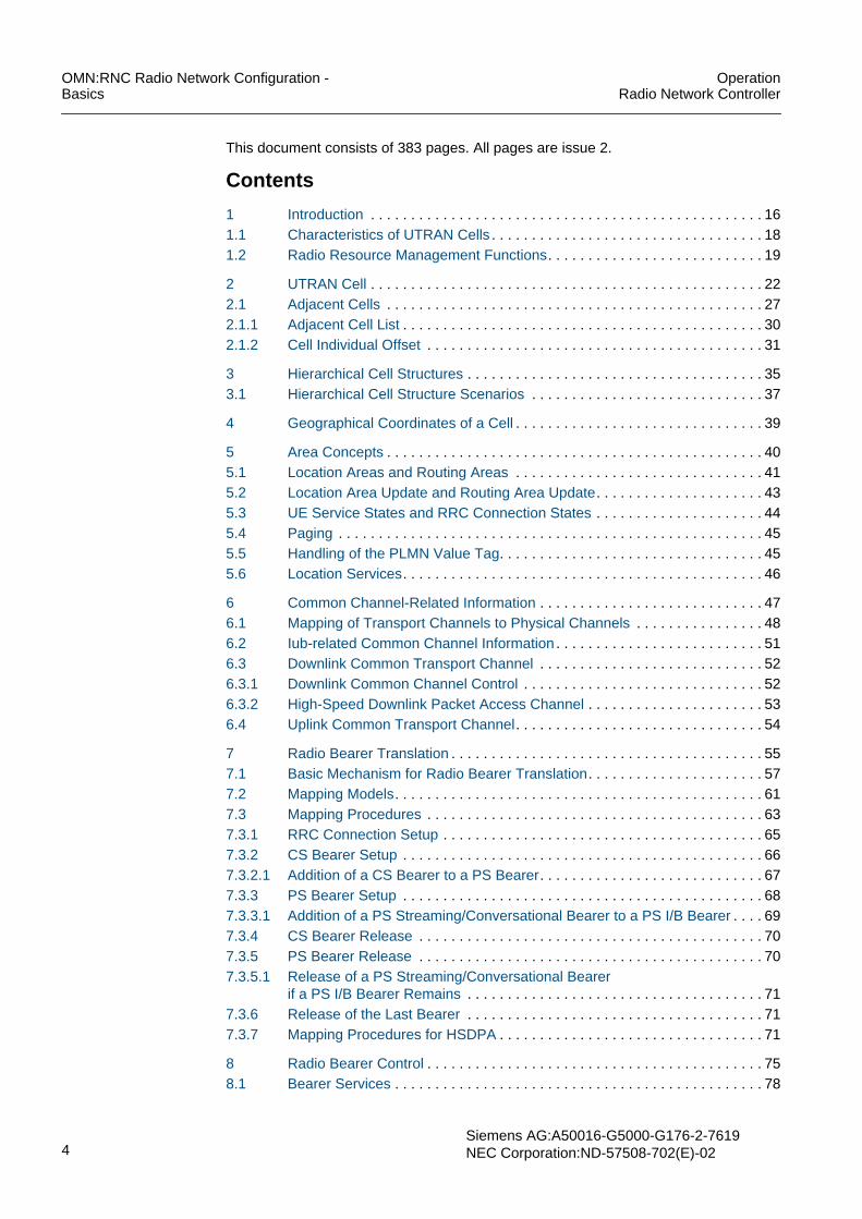
Fig. 3.4 Macro-micro scenario consisting of two layers with different coverage . 38
Fig. 3.5 Macro-micro scenario with possible target cells . . . . . . . . . . . . . . . . . . . 38
Fig. 5.1 Area concepts (cells are not shown). . . . . . . . . . . . . . . . . . . . . . . . . . . . 40
Fig. 5.2 UE registration and connection setup for 3G MSC and 3G SGSN . . . . . 41
Fig. 6.1 Common channel-related information of a cell . . . . . . . . . . . . . . . . . . . . 47
Fig. 6.2 Mapping of transport channels to physical channels . . . . . . . . . . . . . . . 48
Fig. 6.3 RACH handling . . . . . . . . . . . . . . . . . . . . . . . . . . . . . . . . . . . . . . . . . . . . 49
Fig. 6.4 Mapping of transport channels to physical channels for HSDPA . . . . . . 50
Fig. 6.5 Downlink common channel information . . . . . . . . . . . . . . . . . . . . . . . . . 52
Fig. 6.6 Uplink common channel information. . . . . . . . . . . . . . . . . . . . . . . . . . . . 54
Fig. 7.1 Interaction of radio bearer translation with other RRM functions . . . . . . 55
Fig. 7.2 Interactions of radio bearer translation . . . . . . . . . . . . . . . . . . . . . . . . . . 58
Fig. 7.3 Radio bearer translation upon radio bearer setup . . . . . . . . . . . . . . . . . 59
Fig. 7.4 Interactions of radio bearer translation with AC, CC, and RBC . . . . . . . 60
Fig. 7.5 Mapping models on dedicated channels. . . . . . . . . . . . . . . . . . . . . . . . . 61
Fig. 7.6 Mapping model on common channels . . . . . . . . . . . . . . . . . . . . . . . . . . 62
Fig. 7.7 Radio bearer translation steps . . . . . . . . . . . . . . . . . . . . . . . . . . . . . . . . 63
Fig. 7.8 Mapping procedure for an RRC connection setup . . . . . . . . . . . . . . . . . 65
Fig. 7.9 Mapping procedure for a CS bearer setup . . . . . . . . . . . . . . . . . . . . . . . 66
Fig. 7.10 Mapping procedure for the addition of a CS bearer to a PS bearer . . . . 67
Fig. 7.11 Mapping procedure for the setup of an interactive/background bearer . 68
Fig. 7.12 Mapping procedure for the addition of a PS streaming/conversationalbearer to a PS I/B bearer . . . . . . . . . . . . . . . . . . . . . . . . . . . . . . . . . . . . 69

OperationRadio Network Controller
OMN:RNC Radio Network Configuration -Basics
Siemens AG: A50016-G5000-G176-2-7619NEC Corporation: ND-57508-702(E)-02 11
Fig. 7.13 Mapping procedure for the release of a CS bearerif a PS bearer remains . . . . . . . . . . . . . . . . . . . . . . . . . . . . . . . . . . . . . . 70
Fig. 7.14 Mapping procedure for the release of a PS interactive/background bearerif a CS bearer remains . . . . . . . . . . . . . . . . . . . . . . . . . . . . . . . . . . . . . . 70
Fig. 7.15 Mapping procedure for the release of the last bearer . . . . . . . . . . . . . . 71
Fig. 7.16 Radio bearer translation steps . . . . . . . . . . . . . . . . . . . . . . . . . . . . . . . . 72
Fig. 7.17 HS-DSCH and DCH configuration . . . . . . . . . . . . . . . . . . . . . . . . . . . . . 73
Fig. 8.1 Interaction of radio bearer control with other RRM functions. . . . . . . . . 75
Fig. 8.2 UMTS QoS architecture. . . . . . . . . . . . . . . . . . . . . . . . . . . . . . . . . . . . . 78
Fig. 8.3 Trigger events for radio bearer control functions . . . . . . . . . . . . . . . . . . 85
Fig. 8.4 Interworking with other radio resource management functions . . . . . . . 86
Fig. 8.5 Relationship between RRC states, RRC sub-states, and rate states . . 87
Fig. 8.6 UE states and trigger conditions for transport-channel-type switching . 88
Fig. 8.7 General model for PS interactive/background + CS AMR services. . . . 91
Fig. 8.8 UE state model for HSDPA . . . . . . . . . . . . . . . . . . . . . . . . . . . . . . . . . . 93
Fig. 8.9 Channel-type switching . . . . . . . . . . . . . . . . . . . . . . . . . . . . . . . . . . . . . 94
Fig. 8.10 Interactions of transport-channel-type switching control . . . . . . . . . . . . 95
Fig. 8.11 Channel switching between common and dedicated channel . . . . . . . . 96
Fig. 8.12 Coverage area for different bit rates . . . . . . . . . . . . . . . . . . . . . . . . . . . 99
Fig. 8.13 Downlink radio link set quality state transition . . . . . . . . . . . . . . . . . . . 101
Fig. 8.14 Data rate change algorithm based on DL transmitted code powermeasurements . . . . . . . . . . . . . . . . . . . . . . . . . . . . . . . . . . . . . . . . . . . 102
Fig. 8.15 Data rate change algorithm based on UL traffic measurements . . . . . 105
Fig. 8.16 Measuring and averaging buffer utilization . . . . . . . . . . . . . . . . . . . . . 106
Fig. 8.17 Data rate change algorithm based on DL traffic measurements . . . . . 107
Fig. 8.18 Data rate change based on DL traffic measurements . . . . . . . . . . . . . 108
Fig. 8.19 Data rate setting during radio bearer mapping . . . . . . . . . . . . . . . . . . 109
Fig. 8.20 Selecting the initial rate . . . . . . . . . . . . . . . . . . . . . . . . . . . . . . . . . . . . 110
Fig. 8.21 Subsequent rate allocation . . . . . . . . . . . . . . . . . . . . . . . . . . . . . . . . . 112
Fig. 8.22 General model for PS interactive/background + CS AMR services. . . 114
Fig. 8.23 Admission control thresholds . . . . . . . . . . . . . . . . . . . . . . . . . . . . . . . . 121
Fig. 8.24 Thresholds for load-based bit rate adaptation and admission control . 123
Fig. 10.1 Interaction of power control with other RRM functions . . . . . . . . . . . . 135
Fig. 10.2 Control functions and items for power control . . . . . . . . . . . . . . . . . . . 138
Fig. 10.3 Open loop power control . . . . . . . . . . . . . . . . . . . . . . . . . . . . . . . . . . . 140
Fig. 10.4 PRACH structure . . . . . . . . . . . . . . . . . . . . . . . . . . . . . . . . . . . . . . . . . 141
Fig. 10.5 Power ramping mechanism . . . . . . . . . . . . . . . . . . . . . . . . . . . . . . . . . 142
Fig. 10.6 Process flow for the UL DPCCH initial power setting . . . . . . . . . . . . . 143
Fig. 10.7 Allowable range for the DPDCH initial power . . . . . . . . . . . . . . . . . . . 144
Fig. 10.8 The process flow for the DL DPCH initial power setting . . . . . . . . . . . 144
Fig. 10.9 Closed loop power control in UL . . . . . . . . . . . . . . . . . . . . . . . . . . . . . 147
Fig. 10.10 Closed loop power control configuration (UL) . . . . . . . . . . . . . . . . . . . 148
Fig. 10.11 Inner loop power control operational sequence (UL) . . . . . . . . . . . . . . 149
Fig. 10.12 UL DPCCH/DPDCH power determination by inner loop power control 151

OMN:RNC Radio Network Configuration -Basics
OperationRadio Network Controller
12Siemens AG:A50016-G5000-G176-2-7619NEC Corporation:ND-57508-702(E)-02
Fig. 10.13 Inner loop power control operational sequence (DL) . . . . . . . . . . . . . . 152
Fig. 10.14 DL DPCH power determination by inner loop power control . . . . . . . . 154
Fig. 10.15 UL target SIR determination by outer loop power control . . . . . . . . . . . 155
Fig. 10.16 UL outer loop power control . . . . . . . . . . . . . . . . . . . . . . . . . . . . . . . . . 156
Fig. 10.17 OLPC: functional entities and how they interact . . . . . . . . . . . . . . . . . . 157
Fig. 10.18 Interactions of uplink outer loop power control . . . . . . . . . . . . . . . . . . . 158
Fig. 10.19 Algorithm for outer loop power control . . . . . . . . . . . . . . . . . . . . . . . . . 165
Fig. 10.20 DL power drift between radio links . . . . . . . . . . . . . . . . . . . . . . . . . . . . 166
Fig. 10.21 UE with multiple established radio links . . . . . . . . . . . . . . . . . . . . . . . . 167
Fig. 10.22 DL power balancing and inner loop power control . . . . . . . . . . . . . . . . 168
Fig. 11.1 Interaction of admission control with other RRM functions . . . . . . . . . . 173
Fig. 11.2 General flow of admission control . . . . . . . . . . . . . . . . . . . . . . . . . . . . . 176
Fig. 11.3 Interworking between admission control and congestion control . . . . . 180
Fig. 11.4 Congestion thresholds and load levels for admission control . . . . . . . . 181
Fig. 11.5 Interactions between admission control and code allocation . . . . . . . . 183
Fig. 11.6 Hierarchical concept for call admission control . . . . . . . . . . . . . . . . . . . 184
Fig. 11.7 Schematic view of the admission control algorithm . . . . . . . . . . . . . . . 185
Fig. 11.8 Theoretical flow estimation . . . . . . . . . . . . . . . . . . . . . . . . . . . . . . . . . . 186
Fig. 11.9 Load adjustment . . . . . . . . . . . . . . . . . . . . . . . . . . . . . . . . . . . . . . . . . . 187
Fig. 11.10 Interference modelling in the uplink . . . . . . . . . . . . . . . . . . . . . . . . . . . 188
Fig. 11.11 Basic relation of CIR and SIR . . . . . . . . . . . . . . . . . . . . . . . . . . . . . . . . 188
Fig. 11.12 Rate availability function for PS BE bearer . . . . . . . . . . . . . . . . . . . . . . 195
Fig. 11.13 Basic code allocation strategy . . . . . . . . . . . . . . . . . . . . . . . . . . . . . . . 214
Fig. 11.14 Basic code allocation strategy (code tree) . . . . . . . . . . . . . . . . . . . . . . 216
Fig. 12.1 Interaction of congestion control with other RRM functions . . . . . . . . . 219
Fig. 12.2 Interactions of congestion control . . . . . . . . . . . . . . . . . . . . . . . . . . . . . 221
Fig. 12.3 Basic concept for congestion control . . . . . . . . . . . . . . . . . . . . . . . . . . 222
Fig. 12.4 Failure handling of lost events . . . . . . . . . . . . . . . . . . . . . . . . . . . . . . . 226
Fig. 12.5 Congestion handling flow . . . . . . . . . . . . . . . . . . . . . . . . . . . . . . . . . . . 227
Fig. 12.6 Congestion handling in stage 1. . . . . . . . . . . . . . . . . . . . . . . . . . . . . . . 229
Fig. 13.1 Interaction of handover control with other RRM functions . . . . . . . . . . 232
Fig. 13.2 Handover controlled by macro diversity function . . . . . . . . . . . . . . . . . 236
Fig. 13.3 UE handovers . . . . . . . . . . . . . . . . . . . . . . . . . . . . . . . . . . . . . . . . . . . . 237
Fig. 13.4 Cells in the active set and in the monitored set . . . . . . . . . . . . . . . . . . 237
Fig. 13.5 UTRAN handovers . . . . . . . . . . . . . . . . . . . . . . . . . . . . . . . . . . . . . . . . 239
Fig. 13.6 System information block type 11 . . . . . . . . . . . . . . . . . . . . . . . . . . . . . 241
Fig. 13.7 MEASUREMENT CONTROL message . . . . . . . . . . . . . . . . . . . . . . . . 242
Fig. 13.8 Compressed mode . . . . . . . . . . . . . . . . . . . . . . . . . . . . . . . . . . . . . . . . 245
Fig. 13.9 Compressed mode . . . . . . . . . . . . . . . . . . . . . . . . . . . . . . . . . . . . . . . . 246
Fig. 13.10 Intra-frequency handovers . . . . . . . . . . . . . . . . . . . . . . . . . . . . . . . . . . 253
Fig. 13.11 Interactions of intra-frequency handover control. . . . . . . . . . . . . . . . . . 254
Fig. 13.12 Intra-frequency handover procedure. . . . . . . . . . . . . . . . . . . . . . . . . . . 256
Fig. 13.13 Basic intra-frequency handover algorithm . . . . . . . . . . . . . . . . . . . . . . 257
Fig. 13.14 Illustration of event 1A and event 1A’ . . . . . . . . . . . . . . . . . . . . . . . . . . 261

OperationRadio Network Controller
OMN:RNC Radio Network Configuration -Basics
Siemens AG: A50016-G5000-G176-2-7619NEC Corporation: ND-57508-702(E)-02 13
Fig. 13.15 UTRAN handovers. . . . . . . . . . . . . . . . . . . . . . . . . . . . . . . . . . . . . . . . 262
Fig. 13.16 Load-overflow mechanism. . . . . . . . . . . . . . . . . . . . . . . . . . . . . . . . . . 265
Fig. 13.17 Load-balancing mechanism. . . . . . . . . . . . . . . . . . . . . . . . . . . . . . . . . 268
Fig. 13.18 Coverage-triggered handover due to temporaryair-interface conditions. . . . . . . . . . . . . . . . . . . . . . . . . . . . . . . . . . . . . 270
Fig. 13.19 Coverage-triggered handover due to border of frequency layers . . . . 270
Fig. 13.20 Adjacent-cell interference triggered handover . . . . . . . . . . . . . . . . . . . 271
Fig. 13.21 Algorithm for a blind handover . . . . . . . . . . . . . . . . . . . . . . . . . . . . . . . 277
Fig. 13.22 Blind handover procedure . . . . . . . . . . . . . . . . . . . . . . . . . . . . . . . . . . 278
Fig. 13.23 Timing re-initialized handover procedure . . . . . . . . . . . . . . . . . . . . . . 280
Fig. 13.24 Algorithm for a timing re-initialized handover triggered by event 2A . . 281
Fig. 13.25 Algorithm for a timing re-initialized handover triggered by event 2B . . 282
Fig. 13.26 Inter-system handover procedure . . . . . . . . . . . . . . . . . . . . . . . . . . . . 286
Fig. 13.27 Activation of compressed mode for inter-system handover . . . . . . . . . 288
Fig. 13.28 Algorithm for a inter-system handover triggered by event 3A . . . . . . . 289
Fig. 13.29 Deactivation of compressed mode due to event 2F’ . . . . . . . . . . . . . . 290
Fig. 13.30 Triggering of compressed mode if combined measurements are used 292
Fig. 13.31 Network structure with inter-PLMN inter-system handover (example). 299
Fig. 13.32 Evaluation of neighbor cells . . . . . . . . . . . . . . . . . . . . . . . . . . . . . . . . . 300
Fig. 13.33 Inward mobility . . . . . . . . . . . . . . . . . . . . . . . . . . . . . . . . . . . . . . . . . . . 304
Fig. 13.34 Change of the serving HS-DSCH cell within a Node B . . . . . . . . . . . . 305
Fig. 13.35 Change of the serving HS-DSCH cell between two Node Bs . . . . . . . 305
Fig. 13.36 Outward mobility between two Node Bs . . . . . . . . . . . . . . . . . . . . . . . 306
Fig. 13.37 Outward mobility between two RNCs . . . . . . . . . . . . . . . . . . . . . . . . . 307
Fig. 13.38 Outward mobility between two RNCs (SRNC relocation) . . . . . . . . . . 308
Fig. 13.39 Outward mobility between different frequencies/systems . . . . . . . . . . 309
Fig. 14.1 Intra-Frequency Intra-PLMN relocation (UE not involved) . . . . . . . . . . 312
Fig. 14.2 Intra-Frequency Inter-PLMN relocation (UE involved) . . . . . . . . . . . . . 313
Fig. 14.3 Example of Inter-PLMN handover with IMSI based restriction . . . . . . 318
Fig. 14.4 Example of intra-PLMN intra-frequency handover. . . . . . . . . . . . . . . . 320
Fig. 14.5 Scenario in the moment before event 1A is triggeredby the target RNC cell C . . . . . . . . . . . . . . . . . . . . . . . . . . . . . . . . . . . 322
Fig. 14.6 Scenario immediately after the hard handover to cell C triggeredby event 1A . . . . . . . . . . . . . . . . . . . . . . . . . . . . . . . . . . . . . . . . . . . . . 323
Fig. 15.1 Cell selection and reselection in idle mode . . . . . . . . . . . . . . . . . . . . . 330

OMN:RNC Radio Network Configuration -Basics
OperationRadio Network Controller
14Siemens AG:A50016-G5000-G176-2-7619NEC Corporation:ND-57508-702(E)-02
TablesTab. 2.1 UTRA/FDD frequency bands . . . . . . . . . . . . . . . . . . . . . . . . . . . . . . . . . 24
Tab. 2.2 UARFCN definition . . . . . . . . . . . . . . . . . . . . . . . . . . . . . . . . . . . . . . . . . 24
Tab. 2.3 UARFCN definition for additional Band II channels . . . . . . . . . . . . . . . . 25
Tab. 8.1 Single RAB Services. . . . . . . . . . . . . . . . . . . . . . . . . . . . . . . . . . . . . . . . 80
Tab. 8.2 Multi-RAB services . . . . . . . . . . . . . . . . . . . . . . . . . . . . . . . . . . . . . . . . . 81
Tab. 8.3 Rate combinations supported by early UEs . . . . . . . . . . . . . . . . . . . . . 117
Tab. 8.4 Trigger for comparing the load with the bit rate adaptation threshold. . 122
Tab. 8.5 Information defined for all HS-DSCH categories . . . . . . . . . . . . . . . . . 131
Tab. 9.1 Measurements and filter types for higher layer filtering . . . . . . . . . . . . 133
Tab. 10.1 Scaling factor for OLPC . . . . . . . . . . . . . . . . . . . . . . . . . . . . . . . . . . . . 159
Tab. 10.2 Initial UL SIR target parameters . . . . . . . . . . . . . . . . . . . . . . . . . . . . . . 161
Tab. 10.3 OLPC status evaluation . . . . . . . . . . . . . . . . . . . . . . . . . . . . . . . . . . . . 163
Tab. 10.4 OLPC status re-evaluation after handover . . . . . . . . . . . . . . . . . . . . . . 163
Tab. 11.1 Minimum DL spreading factor for single PS BE bearer . . . . . . . . . . . . 199
Tab. 11.2 Allocation/retention priority . . . . . . . . . . . . . . . . . . . . . . . . . . . . . . . . . . 205
Tab. 11.3 Mapping of failure types and cause values. . . . . . . . . . . . . . . . . . . . . . 217
Tab. 12.1 The “etpchr” and “ebd” parameters in congestion handling . . . . . . . . . 228
Tab. 13.1 Handover functions in UMTS . . . . . . . . . . . . . . . . . . . . . . . . . . . . . . . . 240
Tab. 13.2 Procedures for transferring a UTRAN connection to a GSM/GPRS cell. . .294
Tab. 13.3 Interdependency between UE differentiation, load control, cellconfiguration and UE type. . . . . . . . . . . . . . . . . . . . . . . . . . . . . . . . . . . 310
Tab. 14.1 Events that trigger SRNC relocation on Cell_FACH . . . . . . . . . . . . . . . 313
Tab. 14.2 Supported scenarios for SRNC relocation on Cell_DCH . . . . . . . . . . . 316
Tab. 16.1 Parameters for cell configuration . . . . . . . . . . . . . . . . . . . . . . . . . . . . . 334
Tab. 16.2 Parameters for NAS configuration . . . . . . . . . . . . . . . . . . . . . . . . . . . . 336
Tab. 16.3 Timers . . . . . . . . . . . . . . . . . . . . . . . . . . . . . . . . . . . . . . . . . . . . . . . . . . 337
Tab. 16.4 Parameters for adjacent UTRAN cells . . . . . . . . . . . . . . . . . . . . . . . . . 340
Tab. 16.5 Parameters for cell configuration . . . . . . . . . . . . . . . . . . . . . . . . . . . . . 341
Tab. 16.6 Parameters for adjacent GSM cells . . . . . . . . . . . . . . . . . . . . . . . . . . . 342
Tab. 16.7 Parameters for external GSM cells . . . . . . . . . . . . . . . . . . . . . . . . . . . . 343
Tab. 16.8 Parameters for the geographical coordinates of cell. . . . . . . . . . . . . . . 345
Tab. 16.9 Parameters for DL common channel control . . . . . . . . . . . . . . . . . . . . 346
Tab. 16.10 Parameters for UL common channel control . . . . . . . . . . . . . . . . . . . . 347
Tab. 16.11 Parameters for radio bearer translation . . . . . . . . . . . . . . . . . . . . . . . . 349
Tab. 16.12 Radio bearer control parameters . . . . . . . . . . . . . . . . . . . . . . . . . . . . . 350
Tab. 16.13 Node B transmission code power . . . . . . . . . . . . . . . . . . . . . . . . . . . . . 352
Tab. 16.14 Buffer utilization measurement parameters . . . . . . . . . . . . . . . . . . . . . 353
Tab. 16.15 Traffic volume measurement parameters . . . . . . . . . . . . . . . . . . . . . . . 355
Tab. 16.16 Parameters for call tracing . . . . . . . . . . . . . . . . . . . . . . . . . . . . . . . . . . 355
Tab. 16.17 Pre-emption parameters . . . . . . . . . . . . . . . . . . . . . . . . . . . . . . . . . . . . 356
Tab. 16.18 Parameters for admission control needed for higher layer filtering. . . . 356
Tab. 16.19 Parameters for congestion control needed for higher layer filtering . . . 357

OperationRadio Network Controller
OMN:RNC Radio Network Configuration -Basics
Siemens AG: A50016-G5000-G176-2-7619NEC Corporation: ND-57508-702(E)-02 15
Tab. 16.20 Parameters for outer loop power control neededfor higher layer filtering . . . . . . . . . . . . . . . . . . . . . . . . . . . . . . . . . . . . 357
Tab. 16.21 Dedicated measurement information for event A. . . . . . . . . . . . . . . . . 357
Tab. 16.22 Dedicated measurement information for event F. . . . . . . . . . . . . . . . . 357
Tab. 16.23 Parameters for outer loop power control . . . . . . . . . . . . . . . . . . . . . . . 358
Tab. 16.24 Measurement filter coefficient parameter for outer loop power control 358
Tab. 16.25 Parameters for power control initialization . . . . . . . . . . . . . . . . . . . . . . 359
Tab. 16.26 Parameters specified for downlink power balancing . . . . . . . . . . . . . . 360
Tab. 16.27 Parameters for intra-frequency handover control per RNC . . . . . . . . . 361
Tab. 16.28 Parameter for intra-frequency handover controlper UTRAN cell and external UTRAN cell . . . . . . . . . . . . . . . . . . . . . . 363
Tab. 16.29 Parameter for intra-frequency handover controlper adjacent UTRAN cell . . . . . . . . . . . . . . . . . . . . . . . . . . . . . . . . . . . 364
Tab. 16.30 Parameter for radio link failure handling by the Node B . . . . . . . . . . . 364
Tab. 16.31 RNC-wide parameters for inter-frequency handover . . . . . . . . . . . . . . 364
Tab. 16.32 Measurement parameter configured per RNC. . . . . . . . . . . . . . . . . . . 365
Tab. 16.33 Parameters for inter-frequency handover controlper adjacent UTRAN cell. . . . . . . . . . . . . . . . . . . . . . . . . . . . . . . . . . . 367
Tab. 16.34 Parameters for inter-system handover control per RNC . . . . . . . . . . . 368
Tab. 16.35 Parameters for inter-system handover per adjacent GSM cell . . . . . . 371
Tab. 16.36 Parameters for IMSI based handover control . . . . . . . . . . . . . . . . . . . 371
Tab. 16.37 Parameter for cell selection and reselection per UTRAN cell . . . . . . . 372
Tab. 16.38 Parameter for cell selection and reselection controlper adjacent UTRAN cell . . . . . . . . . . . . . . . . . . . . . . . . . . . . . . . . . . . 373
Tab. 16.39 Parameter for cell selection and reselection controlper adjacent GSM cell . . . . . . . . . . . . . . . . . . . . . . . . . . . . . . . . . . . . . 374
Tab. 16.40 Optional parameters for HCS per external UTRAN cell. . . . . . . . . . . . 374
Tab. 16.41 Optional parameters for HCS per external GSM cell . . . . . . . . . . . . . . 374
Tab. 16.42 Parameters for HCS per UTRAN cell. . . . . . . . . . . . . . . . . . . . . . . . . . 375
Tab. 16.43 Parameters per UTRAN cell instance . . . . . . . . . . . . . . . . . . . . . . . . . 376
Tab. 16.44 Parameters that are configurable by the operator per cell. . . . . . . . . . 380
Tab. 16.45 Measurement filter coefficient parameter for congestion control . . . . . 382
Tab. 16.46 HSDPA-related parameters for RAB handling . . . . . . . . . . . . . . . . . . . 382
Tab. 16.47 Parameters for HSDPA measurement information . . . . . . . . . . . . . . . 382
Tab. 16.48 HSDPA-related information on code and power allocation andredimensioning. . . . . . . . . . . . . . . . . . . . . . . . . . . . . . . . . . . . . . . . . . . 383

OMN:RNC Radio Network Configuration -Basics
OperationRadio Network Controller
16Siemens AG:A50016-G5000-G176-2-7619NEC Corporation:ND-57508-702(E)-02
1 Introduction
The Operation Manual OMN:RNC is divided into the following two parts:• Basics
This part of the OMN:RNC provides detailed background information on all availablefunctions. Furthermore, example configurations as well as links to the related featuredescriptions, procedures, and commands in the Command Manual CML:RNC aregiven.The Basics part is subdivided into the following main topics:– Equipment Configuration - Basics– Software Management - Basics– Fault and Test Management - Basics– Performance Management - Basics– Transport Network Configuration - Basics– Radio Network Configuration - Basics– Trace Management - Basics– Network Management - Basics
• ProceduresThe Procedures part of the OMN:RNC provides procedures for all available opera-tion tasks. Entry point for an operation task is the task list that is related to this topic.The procedures contain command sequences required for a specific task andprovide links to the related sections in the Command Manual CML:RNC and to therelated topic in the Basics part.The Procedure part is subdivided into the following main topics:– Master Procedures– Equipment Configuration - Procedures– Software Management - Procedures– Fault and Test Management - Procedures– Performance Management - Procedures– Transport Network Configuration - Procedures– Radio Network Configuration - Procedures– Trace Management - Procedures
This part of the OMN describes configuration aspects of the radio access part:• Characteristics of UTRAN Cells• Radio Resource Management Functions
This chapter provides an overview of all topics required to understand the tasks andrelated procedures, see Task List of the OMN:RNC Radio Network Configuration -Procedures part.
iThis document is prepared as a standard edition that may include descriptions notapplying to your system.

OperationRadio Network Controller
OMN:RNC Radio Network Configuration -Basics
Siemens AG: A50016-G5000-G176-2-7619NEC Corporation: ND-57508-702(E)-02 17
Symbols used
The following symbols are used in this manual:
Fig. 1.1 Used symbols
Reference to another procedure step or chapter
Symbol Explanation
ESD (Electrostatically Sensitive Devices) precautions to be taken
b
h
Use LMT to enter commands
☞ Reference to another chapter or document
Reference to another procedure. Return after finishing.i
i
!DANGER: Danger for life and limbWARNING: Dangers that can lead to serious injuryCAUTION: Dangers that can lead to damage or destruction
NOTE: Helpful information

OMN:RNC Radio Network Configuration -Basics
OperationRadio Network Controller
18Siemens AG:A50016-G5000-G176-2-7619NEC Corporation:ND-57508-702(E)-02
1.1 Characteristics of UTRAN CellsUTRAN cells are the basic elements of the whole network. For an effective networkmanagement and support of call handover, the creation of a cell takes into account thecharacteristics of this cell as well as information on:• Adjacent Cells
The spatial relationships between cells must be specified.• Hierarchical Cell Structures
The operator can assign a hierarchical priority to cells within a cell structure that iscomposed of different layers using different frequencies and cell sizes.
• Area ConceptsThe location area or routing area is used, for example, during CN-initiated paging.
• Geographical Coordinates of a CellThe accurate definition of the position, size, and shape of a cell is an importantnetwork planning parameter that can affect for example the assignment of adjacentcells and handover control.
• Common Channel-Related InformationCommon channels are used simultaneously by several UEs. Their properties arespecified per cell.
Fig. 1.2 shows cell i and adjacent cells as part of a location area.
Fig. 1.2 Cell i and adjacent cells as part of a location area
LA RA URA
LA1
RA1 RA2
RA handled by one 3G SGSNLA handled by one 3G MSC/VLR
RF2
RF1
i

OperationRadio Network Controller
OMN:RNC Radio Network Configuration -Basics
Siemens AG: A50016-G5000-G176-2-7619NEC Corporation: ND-57508-702(E)-02 19
1.2 Radio Resource Management FunctionsRadio Resource Management (RRM) functions are the functions for managing radiointerface resources of the UMTS Terrestrial Radio Access Network (UTRAN). The RRMfunctions aim to ensure an optimum coverage and high call quality as well as tomaximize the system performance through efficient use of radio resources.
Radio resource management functions provided by the RNC are:• Radio Bearer Translation
The radio bearer translation function maps the Radio Access Bearer (RAB)parameters to the Radio Bearer (RB) parameters in order to establish a radio accessbearer between UE and Core Network (CN). This mapping has to be performed foreach new incoming bearer request.
• Radio Bearer ControlThe set of radio bearer control functions aims to optimize the usage of radioresources by adapting the amount of resources assigned to a UE depending on itstraffic load. This is achieved by managing the bit rate adaptation of the radio bearersto the source bit rate and quality of service (QoS) requirements. The mapping takesinto account the actual system load as well as the actual bit rate and quality ofservice requirements of the considered radio bearer.
• Power ControlThe power control function ensures good call quality by adjusting transmissionpowers in uplink and downlink. A low interference among subscribers is an importantissue, because some subscribers share the same frequency band in W-CDMAtechnology.The Node B controls the power of both the UE and its own transmission. It controlsthe output power by means of inner-loop and outer-loop power control mechanisms.
• Admission ControlBasically, the admission control function decides whether or not a new or reconfig-ured radio link can be accepted according to the cell load.
• Congestion ControlThe congestion control function monitors, detects, and handles situations in whichthe system reaches an overload situation with the users already connected.
• Handover ControlThe Handover and Relocation functions ensure the mobility of the user equipmentwhen a UE moves from one cell to another. Handover control transfers a connectedcall to the destination cell.
• Cell Selection and ReselectionThe cell selection and reselection functions are used by UEs in Idle mode. If a UE isswitched on, it selects a suitable cell to camp on. When camped on this cell, the idleUE regularly searches for a better cell. If a better cell is found, that cell is(re)selected.
The Appendix provides topic-oriented tables for an overview of all parameters related toradio resource management.
Fig. 1.3 shows interactions between radio resource management functions.

OMN:RNC Radio Network Configuration -Basics
OperationRadio Network Controller
20Siemens AG:A50016-G5000-G176-2-7619NEC Corporation:ND-57508-702(E)-02
Fig. 1.3 Logical overview on radio resource management functions
The radio resource management functions reside in either the Serving RNC, theControlling RNC, the UE or the Node B. SRNC and CRNC are logical roles of the RNC,see Fig. 1.4.
Fig. 1.4 Logical roles of the RNC
Outer LoopPower Control
Load Control
Admission
CongestionControl
Control/Code Allocation
SRNC CRNC Node B UE
MeasurementControl
Radio BearerTranslation
Radio BearerControl
HandoverControl
RAB assignment,
release, ...
RL setup
removal ...
Transport/physicalchannel
RL addition/
Traffic VolumeThroughput
Measurements
CommonMeasurements
DedicatedMeasurements
Intra-frequencyMeasurements
Traffic VolumeMeasurements
removal ...
reconfiguration ...
RL addition/
OAM Data
OAM Data
Core
Iu
IurUE
Node B
Node B
Iub
Iub
Network
SRNC
DRNC Iu
CRNC
CRNC

OperationRadio Network Controller
OMN:RNC Radio Network Configuration -Basics
Siemens AG: A50016-G5000-G176-2-7619NEC Corporation: ND-57508-702(E)-02 21
The logical roles of the RNC are defined as follows:• Serving RNC (SRNC):
The SRNC is responsible for the functions that are related to a specific radio link.The SRNC holds the current UE context and establishes a link whenever thesubscriber requests communication represents the SRNS. Furthermore, the UE hasaccess to the CN via the SRNS.Fig. 1.5 shows the radio resource management functions in the SRNC.
• Controlling RNC (CRNC):The CRNC is responsible for the functions that are related to a particular cell. TheUE is connected to the CRNC via the Iub interface.Fig. 1.6 shows the radio resource management functions in the CRNC.
• Drift RNC (DRNC):The DRNC controls the next serving area into which the UE is likely to drift during ahandover or relocation. The SRNC and the DRNC are connected via Iur interface.
Fig. 1.5 Radio resource management functions in the SRNC
Fig. 1.6 Radio resource management functions in the CRNC
Radio BearerParameter Control
Radio BearerTranslation
Radio BearerControl
Transport ChannelType Switching
Power Control
Outer Loop PowerControl
Handover Control
Intra-frequencyHandover Control
UE/Node B/SRNCMeasurem. Control
MeasurementReporting Control
Bit RateAdaptation
Initial Values forPower Control
Inter-frequencyHandover Control
Inter-systemHandover Control
Resource
Admission
Load Control
Inter-frequency
Congestion
CongestionControl
Node B Measurem.
MeasurementReporting Control
Power Control
Initial Values forPower Control
Code Allocation,
RestrictionControl
Allocation Control Control
Control
Release
Load Control
Preemption

OMN:RNC Radio Network Configuration -Basics
OperationRadio Network Controller
22Siemens AG:A50016-G5000-G176-2-7619NEC Corporation:ND-57508-702(E)-02
2 UTRAN CellA UTRAN cell is a radio network element that can be uniquely identified by a UE from acell identification that is broadcast over a geographical area from one UTRAN accesspoint, in other words a Node B. Cells are the basic elements of the whole network.Depending on the traffic, a cell can cover a radius of up to several kilometers.
With respect to cell coverage and determined by maximum transmit power in each cellthree types of cells have to be considered:• Macro cells
are preferred for rural areas.• Micro cells
are preferred for urban zones, e.g. streets, commercial zones, stadiums.• Pico cells
mainly provide indoor coverage, e.g. for office buildings, hotels, airports.
With respect to the radiation pattern two types of cells have to be considered:• Omnidirectional cells
reach out in all directions from its hosting Node B.• Sectored cells
cover a sector of e.g. 120˚, seen from the Node B. In this example, a set of threecells is necessary to provide access from all directions.
The cell area is basically defined by the CPICH coverage. The criterion for the CPICHquality is the received Ec/N0. The CPICH quality depends on:• CPICH output power• Interference situation - load• Antenna alignment
Because a cell can only accommodate a limited number of subscribers and transport alimited amount of traffic, a larger number of (smaller) cells must be used to cover areaswhere more traffic is expected. These traffic hot-spot areas, such as highly populatedareas, trade fair centers and railway stations, require several layers of UTRAN cells toguarantee smooth traffic without interruptions and interference. These layers of cells areorganized as Hierarchical Cell Structures. The number of cells per site is defined by thenumber of cells per frequency and the number of available frequencies per operator.
Due to the comparably small size of UTRAN cells and high mobility of subscribers, asubscriber will not be found dwelling in a certain cell for extended amounts of time.When reaching the end of the coverage area of a cell, an ongoing call needs to betransferred to a neighboring cell. This transfer is known as a handover, see HandoverControl.
Cell-related information
Cell-related information is specified by individual commands. This section provides anoverview on commands that are involved. Entry point for related operation tasks is theTask List of the OMN:RNC Radio Network Configuration - Procedures part.
The cell iub CLI command or the GUI Cell window creates Iub interface-related data ofa cell and consists of parameter groups specifying:• The attributes that characterize the cell within a Node B and within the network• The initial values of the inner loop power control, see Inner Loop Power Control• Common channel attributes, see Iub-related Common Channel Information

OperationRadio Network Controller
OMN:RNC Radio Network Configuration -Basics
Siemens AG: A50016-G5000-G176-2-7619NEC Corporation: ND-57508-702(E)-02 23
In addition to the cell iub CLI command, the following information has to be specifiedbefore a cell can be activated for the first time:• cell adc CLI command or the GUI Cell window
This command specifies parameters related to admission control, see AdmissionControl.
• cell cctl CLI command or the GUI Cell windowThis command specifies parameters related to congestion control, see CongestionControl.
• cell rslc CLI command or the GUI Cell windowThis command specifies parameters related to cell selection and reselection control,see Cell Selection and Reselection.
• ulcc CLI command or the GUI Uplink Common Channel windowThis command specifies common uplink channel information, see Uplink CommonTransport Channel.
• dlcc CLI command or the GUI Downlink Common Channel windowThis command specifies common uplink and downlink channel information, seeDownlink Common Channel Control.
The following information can be specified in a second step:• hsdpa CLI command or the GUI High Speed Downlink Packet Access Channel
windowThis command specifies high speed downlink packet access channel for HSDPA,see High-Speed Downlink Packet Access Channel.
• hsrrm CLI command or the GUI HS-DSCH Radio Resource Management windowThis command specifies the HS-DSCH-related radio resource management data.
• cell aci CLI command or the GUI Cell windowThis command specifies adjacent UTRAN cell information, see Adjacent UTRANcells.
• cell agci CLI command or the GUI Cell windowThis command specifies adjacent GSM cell information, see Adjacent GSM cells.
• cell hcs CLI command or the GUI Cell windowThis command specifies parameters for hierarchical cell structures, see HierarchicalCell Structures.
• cell gc CLI command or the GUI Cell windowThis command specifies geographical coordinates, see Geographical Coordinatesof a Cell.
Cell activation and deactivation
In contrast to GSM, the relevant standards for UTRAN do not define an administrativestate for UTRAN cells, nor is there a proper NBAP message to notify changes of such astate over Iub. Therefore there is no way of locking or unlocking a cell. However, amethod is implemented which provides a comparable mechanism. UTRAN cells can beactivated from the CLI by entering the act cell cellid=DDDDD nodebid=DDDD commandand deactivated by entering deact cell cellid=DDDDD nodebid=DDDD. The current sta-tus of a cell can be displayed using the view cell act command. The same functionalityis available from the GUI Cell window. For more information see OMN:RNC NetworkManagement - Basics.
Immediately after creation, cells are deactivated. They need to be activated before theycan provide service. Before a cell is activated, admission control information, congestioncontrol, and reselection control information must be specified by the cell adc, the cellcctl, or the cell rslc CLI commands or the GUI Cell window. Furthermore, uplink and

OMN:RNC Radio Network Configuration -Basics
OperationRadio Network Controller
24Siemens AG:A50016-G5000-G176-2-7619NEC Corporation:ND-57508-702(E)-02
downlink common channels must be specified by the cre ulcc and the cre dlcc CLI com-mands or the GUI Uplink Common Channel and Downlink Common Channel window.
Cells should be deactivated before their settings are modified. Cell deactivation instantlyinterrupts all user traffic. In order to avoid call interruptions and to shift user traffic intoother cells, it is advisable to bar the cell (see Restriction Control) an appropriate timebefore deactivating it.
Setting of the T314 timer in the RNC
The T314RNC timer is related to CS and PS RABs. It is started upon reception of:• CELL UPDATE message if there is at least one cell in the active set.• RL FAILURE INDICATION for the last RL in the active set.
T314RNC is stopped and reset upon receiving the TRANSPORT CHANNELRECONFIGURATION COMPLETE message.
T314RNC is set to the value specified by the T314 parameter of the cell where the RRCconnection was established plus a margin of 2 seconds. The T314 parameter isspecified by the cell iub CLI command or the GUI Cell window.
The UTRA absolute radio frequency channel number
The UMTS Terrestrial Radio Access (UTRA) absolute radio frequency channel number(UARFCN) designates the carrier frequency. Tab. 2.1 shows the definition for the FDD2100 frequency band (Band I) and FDD 1900 frequency band (Band II).
The UMTS Terrestrial Radio Access (UTRA) absolute radio frequency channel number(UARFCN) for uplink and downlink signals is specified by the uarfcn parameter of thecell iub CLI command or the GUI Cell window. Tab. 2.2 shows the definition of theUARFCN.
12 additional channels are defined for Band II (FDD 1900). Tab. 2.3 shows theUARFCN for these channels.
Reference OperatingBand
UL FrequenciesUE transmits,
Node B receives
DL frequenciesUE receives,
Node Btransmits
TX-RX frequencyseparation
(duplex distance)
FDD 2100 I 1920 - 1980 MHz 2110 -2170 MHz 190 MHz
FDD 1900 II 1850 -1910 MHz 1930 -1990 MHz 80 MHz.
Tab. 2.1 UTRA/FDD frequency bands
UARFCN Carrier frequency [MHz]
Uplink 5 * UL Carrier Frequency (MHz) For allowable UL Carrier Frequen-cies see Tab. 2.1.
Downlink 5 * DL Carrier Frequency (MHz) For allowable DL Carrier Frequen-cies see Tab. 2.1.
Tab. 2.2 UARFCN definition

OperationRadio Network Controller
OMN:RNC Radio Network Configuration -Basics
Siemens AG: A50016-G5000-G176-2-7619NEC Corporation: ND-57508-702(E)-02 25
The nominal channel spacing is 5 MHz, but this can be adjusted to optimizeperformance in a particular deployment scenario. The channel raster is 200 kHz whichmeans that the carrier frequency must be a multiple of 200 kHz.
where
F0 = 1924.4 MHz is the first (nominal) carrier center frequency. The spectrum used bythe first carrier extends down to 1920 MHz.
n is an integer running from 0 to 12 for the paired band and describes the channel, as ifa regular 5 MHz allocation was used.
k is used to express a deviation from the regular 5 MHz spacing in steps of 200 kHz.
The carrier allocation is slightly unsymmetrical to the middle of a 5 MHz band becausethe latter is not a multiple of the 200 kHz synthesizer spacing. The value of 1922.4 MHzgives an extra 200 kHz separation to neighboring frequencies outside UMTS.
UARFCN Carrier frequency [MHz]
Uplink 5 * (UL Carrier Frequency (MHz)- 1850.1 MHz))
UL Carrier Frequencies Supported(MHz):1852.5, 1857.5, 1862.5, 1867.5,1872.5, 1877.5, 1882.5, 1887.5,1892.5, 1897.5, 1902.5, 1907.5
Downlink 5 * (DL Carrier Frequency (MHz)- 1850.1 MHz))
DL Carrier Frequencies Supported(MHz):1932.5, 1937.5, 1942.5, 1947.5,1952.5, 1957.5, 1962.5, 1967.5,1972.5, 1977.5, 1982.5, 1987.5
Tab. 2.3 UARFCN definition for additional Band II channels
Fc F0 5 MHz n⋅ 200 kHz k⋅+ +=
i NOTEIf a channel spacing of less than 4.8 MHz is specified by the operator, spurious emissionwill adversely affect the system performance.

OMN:RNC Radio Network Configuration -Basics
OperationRadio Network Controller
26Siemens AG:A50016-G5000-G176-2-7619NEC Corporation:ND-57508-702(E)-02
Example
cre cell iub cellid=1900 nodebid=190 cellid_lcl=0uarfcn=9813,10763 max_dltp=43 t_cell=2 sac=0 rac=1 lac=1901nwom=md2 atdt=mnd tmr_cspu=60 t312=1 n312=1 t313=3 n313=20 n315=1id_ura=1 tpcu=30 t302=4000 n302=3 t307=30 sc_pcpi=101pwr_pcpit=33 po_bch=-3 po_psch=-3 po_ssch=-3 dclc_utran=6 poff-set=16 pwval_max=6 t316=30 t317=180 cio=0 t300=3000 n300=2 t309=5t314=6 t315=180 sac_cbs=1900 plmn_vt=0 po_thra=3 flag_asup=offt304=1000 n304=1 t308=320 sscode=0
cre cell iub cellid=1901 nodebid=190 cellid_lcl=1uarfcn=9813,10763 max_dltp=43 t_cell=4 sac=0 rac=1 lac=1901nwom=md2 atdt=mnd tmr_cspu=60 t312=1 n312=1 t313=3 n313=20 n315=1id_ura=1 tpcu=30 t302=4000 n302=3 t307=30 sc_pcpi=113pwr_pcpit=33 po_bch=-3 po_psch=-3 po_ssch=-3 dclc_utran=6 poff-set=16 pwval_max=6 t316=30 t317=180 cio=0 t300=3000 n300=2 t309=5t314=6 t315=180 sac_cbs=1901 plmn_vt=0 po_thra=3 flag_asup=offt304=1000 n304=1 t308=320 sscode=0
The above commands show the data of two cells that are related to the Iub interface.This two cells belong to the same Node B (nodebid=190 ). cellid identifies these cellswithin the CRNC and cellid_lcl identifies them within the Node B. uarfcn specifies theUMTS Terrestrial Radio Access (UTRA) absolute radio frequency channel number foruplink and downlink signals.
Data related to the Iub interface are specified by the cell iub CLI command or the GUICell window. For more information on RNC database files of sample configurations seeOMN:RNC Equipment Configuration.

OperationRadio Network Controller
OMN:RNC Radio Network Configuration -Basics
Siemens AG: A50016-G5000-G176-2-7619NEC Corporation: ND-57508-702(E)-02 27
2.1 Adjacent CellsTo provide effective support for network management and call handover, the spatialrelationships between cells must be specified. A cell must “know” which cells are itsneighbors. Fig. 2.1 shows cell i and some of its neighbor cells.
Fig. 2.1 Cell i with adjacent intra-frequency, inter-frequency and inter-system cells
For every cell, information on its adjacent cells must be created when the network isplanned. In the event of a handover, an Adjacent Cell List provides information onavailable adjacent cells.
Adjacency relationships are registered in both the cell to be created/modified/deletedand its neighboring cells. A cell and its own adjacency records can only be deleted if alladjacent cell information which references this cell are deleted.
Adjacent cell relationships are specified in two steps:
1. External cell information are required for:– Adjacent UTRAN cells that belong to another RNC– Adjacent GSM cells
2. Adjacent cell information are required for all of the following– Adjacent UTRAN cells– Adjacent GSM cells
The RNC provides the IEs with neighbor cell information in any application responsemessage where applicable. The difference between DL and UL UARFCN can be either190 MHz or 80 MHz.
Entry point for operation tasks related to adjacent cell information and handover controlis the Task List of the OMN:RNC Radio Network Configuration - Procedures part.
External cell information
External cell information are specified once per RNC for:• External UTRAN cells
UTRAN cells are external cells if they belong to another RNC area. They arespecified by the euc CLI command or via the GUI External UMTS Cell window.
• GSM cellsGSM cells are always external within a UTRAN network. They are specified by theegc CLI command or via the GUI External GSM Cell window.
Fig. 2.2 shows cell i with external UTRAN and GSM neighbor cells.
RF2
RF1
UTRANRF1
GERAN
i

OMN:RNC Radio Network Configuration -Basics
OperationRadio Network Controller
28Siemens AG:A50016-G5000-G176-2-7619NEC Corporation:ND-57508-702(E)-02
Fig. 2.2 Cell i with external neighbor cells
Adjacent UTRAN cells
An adjacent UTRAN cell (hereafter simply “adjacent cell”) is a cell that is a physicalneighbor of another cell in a UTRAN network.
Within the UTRAN network, adjacent UTRAN cells can either belong to the same RNCarea or - in the case of external UTRAN cells - to a different one. For external UTRANcells, External cell information have to be configured.
Adjacent UTRAN cells are specified by the cell aci CLI command or the GUI Cellwindow.
Fig. 2.3 Cell i with adjacent UTRAN cells
Adjacent GSM cells
Adjacent GSM cells need to be registered for an Inter-System Handover Control to aGERAN. Adjacent GSM cells are specified by the cell agci CLI command or the GUI Cellwindow. External cell information must be specified for all adjacent GSM cells.
Fig. 2.4 Cell i with adjacent GSM cells
ji
kUTRAN
ji
kUTRAN GERAN
i:cellid=2 k: cellid=4j: cellid=6
i: cellid=2 k: cellid_g=4j: cellid_g=6
rncid=1nodebid=1
rncid=2nodebid=1
rncid=1nodebid=1
j
i
k
i:cellid=2
k: cellid=4j: cellid=6
rncid=1nodebid=1
RF2
RF1
j
k
UTRAN
GERAN
i: cellid=2
k: cellid_g=4j: cellid_g=6
rncid=1nodebid=1
i

OperationRadio Network Controller
OMN:RNC Radio Network Configuration -Basics
Siemens AG: A50016-G5000-G176-2-7619NEC Corporation: ND-57508-702(E)-02 29
Adjacent cell measurements
The RNC supports performance measurement counters that take adjacent cells intoaccount. All adjacent cell measurements are measurements which are related to acenter cell from administrative point of view. They are focused, however, on all singlerelations between the center cell and adjacent UTRAN or GERAN cells.
The purpose of adjacent cell measurements is to:• Observe the mobility of UEs• Localize hot spots in handover/movement failures
Adjacent cells belonging to a different RNS are described by the UMTS Cell Id, that arerncId and cellid of the euc CLI command or the GUI External UMTS Cell window.Adjacent GSM cells are described by the Cell Global Id, that are mcc , mnc , lac_g , andcellid_g of the egc CLI command or the GUI External GSM Cell window.
Due to the high load caused by adjacent cell measurements, the RNC supports only alimited number of simultaneously observed center cells. For more information seeOMN: RNC Performance Measurements.
Example
cre cell aci cellid=1900 nodebid=190 mcc=262 mnc=02cellid_u=152002004 acii=all qoffset1=0 qoffset2=0 cio=0
cre cell aci cellid=1974 nodebid=197 mcc=262 mnc=02cellid_u=151901960 acii=all qoffset1=0 qoffset2=0 cio=0same_ant=false
These cre cell aci CLI commands define the cell with cellid=1974 as adjacent to the cellwith cellid=1900 and vice versa. The cells belong to different Node Bs (nodebid=190 ,nodebid=197 ). cellid_u identifies an adjacent cell uniquely within a UTRAN.
The adjacent cell information indicator acii specifies whether or not the cells areadjacent cells for handover procedures (ho ), selection and reselection procedures (srs ),or both procedures (all ). For more information see Adjacent Cell List.
qoffset1 / qoffset2 specifies the offset between the two cells. qoffset1 is used if themeasurement quantity for cell selection and reselection measurements is set to CPICHRSCP. qoffset2 applies if CPICH Ec/N0 is used.
The same_ant parameter indicates whether or not an adjacent cell with a differentfrequency and the same coverage is located at the same Node B and the same anten-na. same_ant must not be set for intra-frequency neighbor cells.

OMN:RNC Radio Network Configuration -Basics
OperationRadio Network Controller
30Siemens AG:A50016-G5000-G176-2-7619NEC Corporation:ND-57508-702(E)-02
2.1.1 Adjacent Cell ListThe operator specifies for each adjacent cell by the adjacent cell information indicatoracii whether it is an adjacent cell for:• Handover procedures (ho )• Selection and reselection procedures (srs )• Both procedures (all )
This characteristic is indicated for:• Adjacent UTRAN cells by the cell aci CLI command or the GUI Cell window• Adjacent GSM cell by the cell agci CLI command or the GUI Cell window
The operator specifies the GSM and UMTS neighbor cell information during theconfiguration of the UMTS cell information.
UEs in Idle mode and Cell_FACH state continuously monitor neighboring cells. A UEwhich is normally camped on a UMTS cell measures up to 31 adjacent cells per intra-frequency, inter-frequency, or inter-RAT measurement.
Therefore, adjacent cell lists are available for:• Intra-frequency handover
Adjacent cell information indicator set to:– Handover– All
• Inter-frequency handover
Adjacent cell information indicator set to:– Handover– All
• UTRAN-controlled inter-system hard handover
Adjacent cell information indicator set to:– Handover– All
• Inter-System cell change order procedure
Adjacent cell information indicator set to:– Selection and reselection– All
After the completion of a handover sequence, the RNC compares and merges theneighbor cell lists of all cells in the active set. The priority of the neighbor cell informationis as follows:
Latest added cell > Second latest added cell > First added cell
The RNC adds the neighbor cell information of cells that are new in the active set. Theentries of the newest cell in the active set has the highest priority. If a cell is adjacent tomore than one cell in the active list, the cell information of this cell is listed only once. Ifmore than 31 entries for neighbor cells are in the list, the RNC deletes entries related tothe oldest cell in the active set which have the lowest priority. The RNC provides the newneighbor cell lists in the next MEASUREMENT CONTROL message.
i NOTEOperators are recommended to use the OTS to specify the sequence of adjacent cellswithin the neighbor cell lists which is kept by RNC for each cell.

OperationRadio Network Controller
OMN:RNC Radio Network Configuration -Basics
Siemens AG: A50016-G5000-G176-2-7619NEC Corporation: ND-57508-702(E)-02 31
If Intra/Inter PLMN Relocation is active, see Inter/Intra PLMN Relocation orFD: Inter/Intra PLMN Relocation for more information on the handling of neighbor cellinformation.
The neighbor cell information of a UTRAN cell consists of:• rnc CLI command or the GUI RNC window:
– The mobile country code mcc and the mobile network code mnc to identify thePLMN
– The RNC ID rncid to identify the RNC in the PLMN.• cell iub CLI command or the GUI Cell window
– The cell ID cellid to identify the cell in the RNC.– The Location Area Code lac and the Routing Area Code rac .– The UTRA Absolute Radio Frequency Channel Number uarfcn .– The primary CPICH scrambling code sc_pcpi .
The neighbor cell information of a GSM cell consists of:• egc CLI command or via the GUI External GSM Cell window
– The Cell Global Identity that is the mobile country code mcc , the mobile networkcode mnc , the GSM location area code lac_g and the GSM cell ID cellid_g .
– The Absolute Radio Frequency Number arfcn .– The Base Station Identity Code that is the base station color code bcc and the
network color code ncc .
Fig. 2.5 show cell selection/reselection and handover relations.
Fig. 2.5 Cell selection/reselection and handover relations
2.1.2 Cell Individual OffsetThe load among neighboring cells can be balanced by the cell individual offset onadjacent cell level. Thus, unnecessary soft handovers in special areas, for examplecrossings, can be avoided by shifting the cell borders of a single neighbor relation. Thenetwork is optimized on a single cell relation level by adapting the cell form according tospecial geometric requirements on adjacent cell level. This increases the quality and/orthe capacity of the radio network. A handover to an individual cell, for example, can beconfigured dependent whether the UE enters this cell from a highway cell or from ashopping mall cell. For more information on this topic see FD:Cell Individual Offset.
For more information on the usage of the cell individual offset for intra-frequency Intra-PLMN relocation see Triggers for Intra-Frequency Intra-PLMN Relocation (Iur InterfaceNot Present).
Frequency 2:
Frequency 1:

OMN:RNC Radio Network Configuration -Basics
OperationRadio Network Controller
32Siemens AG:A50016-G5000-G176-2-7619NEC Corporation:ND-57508-702(E)-02
The offset can be positive or negative and the UE will add this offset to the measurementquantity before it evaluates the occurrence of a reporting event, see Fig. 2.6:• Decreasing the cell individual offset of a cell
UEs in this area tend to move to this cell.• Increasing the cell individual offset of a cell
UEs move away or are not “invited” to this cell.
Fig. 2.6 Cell individual offset
The information of cell individual offsets on adjacent cell level is provided for the UE bysystem information broadcast if the UE is in Idle mode, CELL_FACH, or CELL_URAstate. If the UE is in CELL_DCH state, these cell individual offsets are signaled in theMEASUREMENT CONTROL message.
The cell individual offset of a cell i is configured by the cio parameter of the cell iub CLIcommand or the GUI Cell window. If this value is not known, for example if that cell is inthe DRNC, then the default value 0 is taken.
The cell individual offset on adjacent cell level, for example the cell individual offset of acell i seen from a cell j, is configured by:• The cio parameter of the cell aci CLI command for adjacent UTRAN cells• The cio parameter of the cell agci CLI command for adjacent GSM cells
The same functionality is provided by the GUI Cell window.
If cell j is in the DRNC, then the value of the cio parameter is sent in the neighbor cellinfo list of the RNSAP RL SETUP/ADDITION RESPONSE message after thesetup/addition of cell j. The default value 0 is taken if the value of the cio parameter isnot sent. The cell individual offset on adjacent cell level is optional in the RNSAP RLSETUP/ADDITION RESPONSE message.
In DCH_connected mode, the cell individual offsets of both the cells in the active set andof their neighbor cells are used by the UE for the intra-frequency, inter-frequency, andinter-system handover decisions.
The cell individual offsets are signaled to the UE in the following lists:• IntraFreqCellInfolist• InterFreqCellInfolist• InterRATCellInfolist
j: cio > 0
k: cio < 0
UE
UE
UE
UE

OperationRadio Network Controller
OMN:RNC Radio Network Configuration -Basics
Siemens AG: A50016-G5000-G176-2-7619NEC Corporation: ND-57508-702(E)-02 33
These CellInfolists are signaled when setting up/modifying the intra-frequency, inter-frequency and inter-RAT measurements with the RRC MEASUREMENT CONTROLmessage whenever the activation criteria of the above measurements are fulfilled.
The information on the cell individual offset related to inter-frequency adjacent cells issent in the MEASUREMENT CONTROL message used to setup/modify the measure-ments 2D/2F. These measurements are setup after the UE switches to CELL_DCH ifcertain condition criteria are fulfilled. During the inter-frequency handover procedure, thequality of the virtual active set is evaluated ignoring the cell individual offset. Forselecting the cells in the virtual active set, however, the cell individual offset is taken intoaccount because the same measurements are used as for intra-frequency handover,i.e. measurements 1A, 1B, and 1C.
The GSM adjacent cell information, that includes the information on cell individualoffsets, is sent in the MEASUREMENT CONTROL message used to setup the 3Ameasurement. Measurement 3A is set up whenever event 2D’ has been triggered andall the remaining condition are fulfilled.
Upon cell addition, cell deletion, or cell replacement, the cell individual offsets of boththe cells in the active set and their neighbor cells is updated using the informationsignaled in the MEASUREMENT CONTROL message. If the cell individual offset of anexisting cell changes, the updated value is provided for the UE without removing the cell.
The advantages to use the cell individual offset to make the handover control adjacentcell specific are:• The cell individual offset is the only handover parameter supported via the Iur
interface.• If the cell individual offset changes, for example if a new cell with different cell
individual offset is added to the active set, the measurement control has to bemodified only. In contrary, if the hysteresis changes, the complete measurementcontrol has to be resent.
• The cell individual offset is defined on an adjacent cell basis in the 3GPP standard,in contrary to the hysteresis, which might be only defined on a cell basis.
• The cell individual offset can be used to set cell individual hysteresis and ranges.
This section provides examples on how the cell individual offsets can be determined. Itcan be seen that the master cell is always the newest cell from the active set.
Cell addition
Assuming that the UE is in soft handover with the cells i and j and that cell k is added,the cell individual offsets are overwritten by the cell individual offsets of the adjacentcells of the newly added cell. Fig. 2.7 shows three cells with their adjacent intra-frequency cells.
Fig. 2.7 Cells with their adjacent intra-frequency cells
ij
k

OMN:RNC Radio Network Configuration -Basics
OperationRadio Network Controller
34Siemens AG:A50016-G5000-G176-2-7619NEC Corporation:ND-57508-702(E)-02
In Fig. 2.8, the blue cell and finally the red cell are added to the green cell. The boldbounded cells mark the active set cells. The transparent colors indicate from which cellthe cell individual offset is taken.
Fig. 2.8 The blue cell and the red cell are added to the green cell
Cell deletion
If a cell is deleted, the cell individual offset of the deleted cell does not change to avoidping-pong effects. Furthermore, if the active set reduces from 3 to 1, the cell individualoffset of the remaining active set cell, and the cell individual offsets of the two cells justdeleted from the active set remain unchanged.
Fig. 2.9 illustrates the behavior for the deletion of the red and the green cell.
Fig. 2.9 Configurations after deletion of the red and the green cell
Cell replacement
Assuming that the UE is in soft handover with cells i, j, and k, the cell individual offsetsare determined via deletion of cell k followed by the addition of cell l if cell k has to bereplaced with cell l.
ij
ki ji
kj
i
kj j
ji
j
The green cell is deleted first
The red cell is deleted first

OperationRadio Network Controller
OMN:RNC Radio Network Configuration -Basics
Siemens AG: A50016-G5000-G176-2-7619NEC Corporation: ND-57508-702(E)-02 35
3 Hierarchical Cell StructuresHierarchical cell structures (HCS) are composed of different layers using differentfrequencies and cell sizes. By assigning hierarchical priority to cells, the operatorcreates a network with different layers. Each layer is reserved for a clearly defined typeof traffic whereas handovers are possible if, for example, congestions occur. Fig. 3.1shows an example of a hierarchical cell structure. The numbers describe the differentlayers in the hierarchy. Number 1 is the highest hierarchical layer with the highest prior-ity, that is typically the smallest cell.
Fig. 3.1 Hierarchical cell structures
Two different basic radio resource management mechanisms are provided for thesupport of hierarchical cell structures:• Load Control
Load control distributes the load within the network. This function determines thefrequency layer and cell to which a UE with a dedicated channel is assigned.
• Handover Control
Handover control decides on:– Intra-frequency soft and softer handover– Inter-frequency handover– Inter-system handover to GSM
For more information on inter-frequency handover and the related radio resourcemanagement mechanisms see Inter-Frequency Handover Control. Hierarchical cellstructures in Idle and Fach connected mode are supported via cell selection andreselection, see Cell Selection and Reselection.
Entry point for related operation tasks is the Task List of the OMN:RNC Radio NetworkConfiguration - Procedures part.
The operator controls the transition of a UE connection between two layers or betweenany two cells via measurements on target cells and via parameter settings. Thereforehysteresis and cell border offset effects can be achieved. The UE uses SIB3 and SIB11to perform measurements, rank and select cells. The corresponding procedures aredescribed in 3GPP TS 25.304.
1
2
3

OMN:RNC Radio Network Configuration -Basics
OperationRadio Network Controller
36Siemens AG:A50016-G5000-G176-2-7619NEC Corporation:ND-57508-702(E)-02
The UE measures neighboring cells to locate a suitable cell to camp on. Thesemeasurements can be prioritized by the following thresholds:• Sintrasearch (intra-frequency)• Sintersearch (inter-frequency)• Ssearch,RAT (inter-system)
The thresholds are specified per cell instance by the cell hcs CLI command or the GUICell window.
Example
cre cell hcs cellid=1975 nodebid=197 pri_hcs=0 qhcs=0 tm_pnlt=0offset1_temp=6 offset2_temp=3 tcrmax=0 ncr=8 tcrmax_hyst=0flag_sshcs=on ss_hcs=11 flag_shcsrat=on shcs_rat=1
The above cre cell hcs CLI command specifies parameters for hierarchical cellstructures for the cell with cellid=1000 and the Node B with nodebid=100 .
pri_hcs indicates the HCS priority level for serving cells and qhcs specifies the qualitythreshold levels for applying prioritized hierarchical cell reselection. The penalty timetm_pnlt indicates the temporary offset that is applied for a neighboring cell. For theduration of tm_pnlt , offset1_temp / offset2_temp specify the offset applied to thehandover and reselection criteria for a neighboring cell. offset1_temp is used if themeasurement quantity for cell selection and reselection measurements is set to CPICHRSCP. If CPICH Ec/N0 is used, offset2_temp applies.
tcrmax specifies the time for evaluating the number of cell reselection specified by ncr .ncr indicates the maximum number of cell reselections permitted for a low-mobility UEduring the time specified by tcrmax . tcrmax_hyst indicates the additional time periodbefore the UE can revert to low-mobility measurements.
flag_sshcs indicates whether HCS is used. ss_hcs indicates the threshold value forcell reselection by HCS. flag_shcsrat indicates whether or not shcs_rat is used.shcs_rat specifies the inter-RAT specific threshold that is used in the measurementrules for cell reselection when HCS is used.

OperationRadio Network Controller
OMN:RNC Radio Network Configuration -Basics
Siemens AG: A50016-G5000-G176-2-7619NEC Corporation: ND-57508-702(E)-02 37
3.1 Hierarchical Cell Structure ScenariosHierarchical cell structure scenarios are composed of any number of FDD frequencylayers. The coverage of overlapping cells on different frequencies can be identical ordifferent. In scenarios with 3 or more frequency layers, there are mixed scenarios wherethe cell coverage area for overlapping cells is identical to some frequency layers anddifferent from others. The hierarchical cell structure scenario within a UMTS network,however, depends on the number of available frequencies and the Node B capabilities.
Fig. 3.2 shows a cell structure scenario consisting of two macro layers whereoverlapping cells of two different frequencies have identical coverage.
Fig. 3.2 Macro-macro scenario consisting of two layers with identical coverage
The timing and path loss relation for inter-frequency handovers is known for the cells ofthe same Node B that are provided by the same antenna. These cells are targets for aTiming Maintained Handover. Furthermore, inter-frequency handovers are possible tocells of a different frequency residing on a different antenna where the path loss and tim-ing relations are not known. These cells are targets for a timing re-initialized handover.
Fig. 3.2 shows the possible inter-frequency handover targets for a cell structurescenario consisting of two macro layers where overlapping cells of two differentfrequencies have identical coverage.
Fig. 3.3 Macro-macro scenario with possible target cells
There are two cell structure scenarios consisting of two layers where the cell coveragein different frequency layers is different:• The cell sizes are the same, but the coverage areas of the cells are different, for
example a macro-macro scenario with different cell coverage.• The cell size and the cell coverage area are different, for example a micro-macro
deployment.
In either case, timing re-initialized handover is triggered if the handover conditions aresatisfied.
RF2
RF1
RF2
RF1
Under the same Node B
target cell for a blind handovertarget cell for a timing re-initialized handover
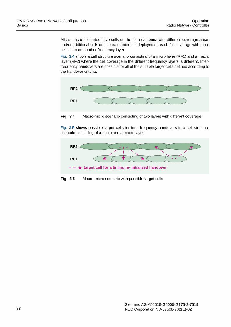
OMN:RNC Radio Network Configuration -Basics
OperationRadio Network Controller
38Siemens AG:A50016-G5000-G176-2-7619NEC Corporation:ND-57508-702(E)-02
Micro-macro scenarios have cells on the same antenna with different coverage areasand/or additional cells on separate antennas deployed to reach full coverage with morecells than on another frequency layer.
Fig. 3.4 shows a cell structure scenario consisting of a micro layer (RF1) and a macrolayer (RF2) where the cell coverage in the different frequency layers is different. Inter-frequency handovers are possible for all of the suitable target cells defined according tothe handover criteria.
Fig. 3.4 Macro-micro scenario consisting of two layers with different coverage
Fig. 3.5 shows possible target cells for inter-frequency handovers in a cell structurescenario consisting of a micro and a macro layer.
Fig. 3.5 Macro-micro scenario with possible target cells
RF2
RF1
RF2
RF1
target cell for a timing re-initialized handover

OperationRadio Network Controller
OMN:RNC Radio Network Configuration -Basics
Siemens AG: A50016-G5000-G176-2-7619NEC Corporation: ND-57508-702(E)-02 39
4 Geographical Coordinates of a CellThe accurate definition of the position, size and shape of a cell is an important networkplanning parameter that can affect the assignment of adjacent cells, handover control,etc.
Information on the position of a cell’s antenna and the positions of the vertices of apolygon approximately representing the cell’s boundaries is specified by the cell gc CLIcommand or the GUI Cell window. Entry point for related operation tasks is the Task Listof the OMN:RNC Radio Network Configuration - Procedures part.
The position of a cell’s antenna is specified by the geographical coordinates of UTRANaccess point position gc_uapp . This parameter stores information describing thelatitude and longitude of the cell’s antenna.
A cell’s shape is approximated by a polygon; the positions of this polygon’s vertices arespecified by the geographical coordinates of cell polygon data gc_cpd . A minimum ofthree vertices are specified; a maximum of 16 is allowed. For each vertex, the latitudeand longitude are defined.
Latitude and longitude are calculated using the formulas introduced in the parameterdescription of gc_uapp and gc_cpd in the command manual.
Example
cre cell gc cellid=1900 nodebid=190 gc_uapp=n1234567#-8381140
The above cell gc CLI command specifies geographical coordinates for the cell withcellid=1900 and the Node B with nodebid=190 . gc_uapp specifies informationdescribing the latitude and longitude of the cell’s antenna.

OMN:RNC Radio Network Configuration -Basics
OperationRadio Network Controller
40Siemens AG:A50016-G5000-G176-2-7619NEC Corporation:ND-57508-702(E)-02
5 Area ConceptsThe location area or routing area is used, for example, during CN-initiated paging. Atemporary identity is assigned to the UE. This identity is unique within a location area orrouting area.
For locating a subscriber, the network is divided into:• Location areas for CS services
The mapping between location area and RNC is handled within the MSC/VLR towhich the location area is assigned.A service area can be mapped on one or more cells within a location area. A cell isallowed to belong to more than one service areas.
• Routing areas for PS servicesThe mapping between routing area and RNC is handled within the SGSN/SLR thatowns this routing area.The UTRAN registration area is defined as subset of a routing area.
The RNC handles the mapping between location area and cells and between routingareas and cells, see Fig. 5.1.
Fig. 5.1 Area concepts (cells are not shown)
The location area code lac , the routing area code rac , and the service area code sacare specified by the cell iub CLI command or the GUI Cell window. Entry point for relatedoperation tasks is the Task List of the OMN:RNC Radio Network Configuration -Procedures part.
Example
cre cell iub cellid=1900 nodebid=190 cellid_lcl=0uarfcn=9813,10763 max_dltp=43 t_cell=2 sac=0 rac=1 lac=1901nwom=md2 atdt=mnd tmr_cspu=60 t312=1 n312=1 t313=3 n313=20 n315=1id_ura=1 tpcu=30 t302=4000 n302=3 t307=30 sc_pcpi=101pwr_pcpit=33 po_bch=-3 po_psch=-3 po_ssch=-3 dclc_utran=6 poff-set=16 pwval_max=6 t316=30 t317=180 cio=0 t300=3000 n300=2 t309=5t314=6 t315=180 sac_cbs=1900 plmn_vt=0 po_thra=3 flag_asup=offt304=1000 n304=1 t308=320 sscode=0
The above cell iub CLI command show the iub-related data of the Node B withnodebid=190 . lac identifies the location area code and sac the service area code. racspecifies the routing area code and id_ura the UTRAN registration area ID.
LA RA URA
LA1 LA2 LA3
RA1 RA2 RA3 RA4 RA5
RA handled by one 3G SGSNLA handled by one 3G MSC/VLR

OperationRadio Network Controller
OMN:RNC Radio Network Configuration -Basics
Siemens AG: A50016-G5000-G176-2-7619NEC Corporation: ND-57508-702(E)-02 41
5.1 Location Areas and Routing AreasThe following sections briefly describes area concepts and the relationships betweenthem. Fig. 5.2 shows the UE registration and connection principles within the UMTS.For more information see TED:UTRAN COMMON.
Fig. 5.2 UE registration and connection setup for 3G MSC and 3G SGSN
Location area (LA)
A location area is defined as a cluster of adjacent cells belonging to RNCs that areconnected to the same CN node. A location area is handled by only one CN-servingnode, i.e., by one 3G-MSC/VLR. The number of cells is at least one and at most theentire VLR area. The operator can define location areas equal to BSC/RNC areas orMSC areas.
The optimum size of a location area in terms of cells is limited by the location updateload and the paging load:• Small location area:
– Less signaling load for paging on BSC/RNC and MSC– High load for location updates on BSC/RNC and MSC
• Large location area:– High paging load for the BSC/RNC and MSC– Low load for location updates on BSC/RNC and MSC
The location area code (LAC) is an integer value (1 to 65533, 65535). The RNC can use16 LAC values.
UEPS stateCS state
UTRAN
CS state
3G MSC/VLR
CS service domain
PS state
3G SGSN/SLR
PS service domain
CS location PS location
HLR
Common
Two CN service domains
subscriptiondatabase
Two Iu signaling connections
UTRAN withdistributionfunctionality
One RRC connection

OMN:RNC Radio Network Configuration -Basics
OperationRadio Network Controller
42Siemens AG:A50016-G5000-G176-2-7619NEC Corporation:ND-57508-702(E)-02
Routing area (RA)
A routing area is a subset of a single location area. It is defined as a cluster of cellsbelonging to RNCs that are connected to the same CN node. A routing area is handledby only one CN serving node, i.e., by one 3G-SGSN.
The cells are typically adjacent in order to maximize the dwelling time within one routingarea and to prevent a large number of routing area updates. A routing area consists ofat least one cell and at most the entire location area. More than one routing areas canbe defined per location area.
Minimum and maximum values in terms of number of cells are limited by:• Paging resulting in signaling load on BSC/RNC and SGSN• Routing area update load of the SGSN, i.e., the size of a routing area
The routing area code (RAC) is an integer value between 0 and 255 defined inside alocation area. The operator specifies the routing area identity (RAI) that identifies one ormore cells. It is broadcast as system information and is used by the UE to determinewhether the routing area changes while changing a cell.
The following rules apply for the routing area identity:• RAC is only unique when presented together with LAI• LAI = MCC + MNC + LAC• RAI = MCC + MNC + LAC + RAC
The Mobile Country Code (MCC) and the Mobile Network Code (MNC) specify thepublic land mobile network (PLMN).
A UTRAN registration area is a subset of a registration area. The UTRAN registrationarea consists of 4-7 cells surrounding on central cell. A URA may have up to 15 relationswith other RNC Identifiers which would indicate that the URA stretches out over the areacovered by these RNCs. The absence of relations with other RNCs indicates that theURA is completely contained within the coverage area of this single RNC.
A cell must be allocated to at least one URA, otherwise it is not allowed for UEs inura_PCH connection state. In this case, the absence of SIB2 (system information block2 which, among others, broadcasts a list of available URA IDs) causes the UE to bemoved into cell_PCH state and back into ura_PCH at the next cell update, if possible.
A cell can be allocated to a maximum of nine [0..8] URAs.
UTRAN registration area (URA)
A UTRAN registration area is a subset of a registration area. The UTRAN registrationarea consists of 4-7 cells surrounding one central cell. Other assignments are possiblebut a URA must not cross the border of two neighboring RNC areas. One URA identifiermust be defined per cell, otherwise the cell cannot be entered by UEs in URA_PCHconnection state.

OperationRadio Network Controller
OMN:RNC Radio Network Configuration -Basics
Siemens AG: A50016-G5000-G176-2-7619NEC Corporation: ND-57508-702(E)-02 43
Service area (SA)
A service area can be mapped on one or more cells within a location area. However, thismapping is handled within UTRAN and is invisible to the core network. A cell is allowedto belong to more than one service area.
The service area matches:• One cell for the broadcast (BC) domain• One or more cells for the CS and PS domain, for example the cells of one or more
base stations
The service area code (SAC) has a length of two octets and is unique within the locationarea.
The service area identifier (SAI) is defined as:
SAI = MCC + MNC + LAC + SAC
5.2 Location Area Update and Routing Area UpdateA UE invokes a location area update procedure via the 3G-MSC if it changes thelocation area or if a certain timer has expired. If a new location area is in an area servedby another CN node, the location area update also triggers the registration of thesubscriber in the new CN node and a location update for CS services toward the HLR.
The procedure determines:• The location of the mobile subscriber in terms of the VLR address for the HLR• The authentication parameters of the mobile subscriber for the VLR concerned
Location area update is initiated by the UE if it is in state CS_IDLE independently of thePS state. If the UE is in state CS_IDLE and in state PS_CONNECTED, it initiates alocation area update when it receives information indicating a new location area.
A UE invokes a routing area update procedure via the 3G-SGSN/SLR if it changes therouting area. If the new routing area is in an area served by another CN node, the routingarea update also triggers the registration of the subscriber in the new CN node and alocation update for PS services toward the HLR.
The procedure determines:• The routing area of the mobile subscriber for the HLR• The authentication parameters of the mobile subscriber for the 3-SGSN SLR
concerned
Routing area update is initiated by the UE if it is in state PS_IDLE independently of theCS state. If the UE is in state PS_IDLE and in state CS_CONNECTED, it initiates arouting area update when it receives information indicating a new routing area. If the UEis in state PS_CONNECTED, it initiates a routing area update as soon as the routingarea identity in the mobility management (MM) system information changes.

OMN:RNC Radio Network Configuration -Basics
OperationRadio Network Controller
44Siemens AG:A50016-G5000-G176-2-7619NEC Corporation:ND-57508-702(E)-02
5.3 UE Service States and RRC Connection StatesThis section describes the UE service states for CS and/or PS services and thecorresponding RRC connection states.
A state NULL has been defined for UEs that are known to neither the CS nor the PSdomain: CS_DETACHED and PS_DETACHED.
No location area update is required in the state CS_CONNECTED, whereas in the statePS_CONNECTED an update is initiated.
CS Services• CS_DETACHED:
– The UE is not reachable for CS services– The UE does not initiate location area updates at a location area change– There are no periodic CS service updates
• CS_IDLE:– The UE is reachable by paging for CS services– The UE initiates location area updates at location area changes– The UE may initiate periodic CS service updates
• CS_CONNECTED:– The UE has signaling connection for CS services to the core network– The UE does not initiate location area updates– There are no periodic CS service updates
In CS_CONNECTED mode the position of the UE is known on a cell basis. The currentcell is known by location update, i.e., updating the cell ID. A location area update mustbe carried out at connection release.
PS services• PS_DETACHED:
– The UE is not reachable tor PS services– The UE does not initiate routing area updates at routing area changes– The are no periodic PS service updates
• PS_IDLE:– The UE is reachable by paging for PS services– The UE initiates routing area updates at a routing area change– The UE may initiate periodic PS service updates
• PS_CONNECTED:– The UE has signaling connection for PS services to the core network– The UE initiates routing updates when the routing area identity in the MM chang-
es– There are no periodic PS service updates
Correlation between RRC connection states and UE service states
RRC connection states and UE service states correspond as follows:• RRC connected:
CS_CONNECTED and/or PS_CONNECTED• RRC idle:
neither CS_CONNECTED nor PS_CONNECTED
The state RRC connected includes CELL_DCH, CELL_FACH, CELL_PCH andURA_PCH mode. For more information see State Management.

OperationRadio Network Controller
OMN:RNC Radio Network Configuration -Basics
Siemens AG: A50016-G5000-G176-2-7619NEC Corporation: ND-57508-702(E)-02 45
5.4 PagingPaging information is transmitted to an individual UE in Idle mode using the pagingcontrol channel (PCCH). A paging message to the RNC contains the paging area IDparameters, i.e., the information on the area in which the paging message is to be broad-cast. The location area or routing area is taken from a cell identifier list. If a UMTS cellis paged, the cell identifier list contains only one dummy cell from which to derive thelocation area. The RNC itself creates the list of cells to be paged in. Paging is completelyindependent for CS and PS services.
The paging procedure consists of two parts:• The part from core network to RNC via Iu interface (RANAP)• The UTRAN-internal part via Iub interface (NBAP)
The core network is responsible for the paging repetition over the Iu interface if pagingis unsuccessful.
The paging load per area within the UTRAN corresponds to the number of pagingrequests in this area. The larger the area, the more paging messages are necessary.Although the number of paged UEs is constant in the whole network, the UE must bepaged within the complete paging region resulting in a paging load in each cell of theregion.
Paging can be initiated in the following UE service states:• CS_IDLE or PS_IDLE state: CN paging for CS and PS• CELL_PCH state: UTRAN paging for PS• URA_PCH state: UTRAN paging for PS
5.5 Handling of the PLMN Value TagA PLMN Value Tag is used to indicate a unique setting of MCC+MNC+LAC/RAC. TheRNC checks automatically if there are two cells using the same PLMN Value Tag butwith different LAC/RAC settings controlled by the same RNC and rejects such configu-ration. The UE uses the PLMN Value Tag to initiate location/routing area update andselective system information reading. The PLMN value tag plmn_vt is specified by thecell iub CLI command or the GUI Cell window.

OMN:RNC Radio Network Configuration -Basics
OperationRadio Network Controller
46Siemens AG:A50016-G5000-G176-2-7619NEC Corporation:ND-57508-702(E)-02
5.6 Location ServicesLocation services (LCS) provide the capability to determine the geographic location of aUE. This information may be requested by the UE itself or by a client within or attachedto the CN. Location services are the basis for new services such as:• Localized advertising, tracking services (e.g. fleet management), navigation• Location dependent billing• Enhanced support of emergency calls by determining the originator’s location• Support of legally required or sanctioned services such as lawful intercept
It is the responsibility of the UE, Gateway Mobile Location Centre (GMLC), HLR, VMSCand MSC to check all preconditions (such as the user’s privacy settings) when a locationrequest is issued by a client other than the UE itself. Once this has been done and therequest is granted, the RNC returns the UE’s position to the MSC which, via the GMLC,passes it on to the requesting client.
The current release supports the Cell ID method and offers an accuracy of about 500 mup to 2000 m, depending on cell size. Requests are handled according to a priorityranking: highest priority is allocated to requests which are related to an emergency call,followed by requests pertaining to an ongoing call, followed by those which are notrelated to an established connection. The location of the UE is determined regardless ofits RRC connection state. If the UE is in Idle mode, it is paged by the core network.Otherwise, if the UE’s RRC connection mode does not provide for identification of thecell that it is camped on, it is paged by the RNC. If there is a soft handover in progressand there are cells involved which are owned by a drift RNC, the required data iscollected from the DRNC via Iur.

OperationRadio Network Controller
OMN:RNC Radio Network Configuration -Basics
Siemens AG: A50016-G5000-G176-2-7619NEC Corporation: ND-57508-702(E)-02 47
6 Common Channel-Related InformationCommon channels are used simultaneously by several subscribers for:• System information that is important for all UEs registered with an individual Node B• Small amounts of packet-oriented traffic for individual UEs which are routed by
in-band identification.
The properties of common channels are specified per cell. Fig. 6.1 provides an over-view of the common channel-related information of a cell and the related CLI commandsand GUI windows. In contrast to common channels, dedicated channels are exclusivelyallocated to a UE for a certain period of time.
Fig. 6.1 Common channel-related information of a cell
P-CPICH
BCH
S-CCPCH
FACH
AICHP-SCH S-SCH P-CCPCH PICH PRACH
RACHPCH
cell iub command ulcc commanddlcc command
Cell window Downlink CommonChannel window
Downlink CommonChannel window
cell

OMN:RNC Radio Network Configuration -Basics
OperationRadio Network Controller
48Siemens AG:A50016-G5000-G176-2-7619NEC Corporation:ND-57508-702(E)-02
6.1 Mapping of Transport Channels to Physical ChannelsThe following describes common transport channels and the mapped physical channelsused for radio resource management, see Fig. 6.2. For more information on radiochannels see Radio Bearer Translation and TED:UTRAN COMMON. Entry point forrelated operation tasks is the Task List of the OMN:RNC Radio Network Configuration -Procedures part.
Fig. 6.2 Mapping of transport channels to physical channels
The Paging Channel (PCH) is a common downlink transport channel used to carrycontrol information to a UE when the system does not know the location cell of the UE.The identification of the UE that currently has no connection to the UTRAN is sent viathe PCH.
The Secondary Common Control Physical Channel (S-CCPCH) carries the PCH. ThePaging Indicator Channel (PICH) is always associated with the S-CCPCH to which aPCH transport channel is mapped. It is a fixed-rate physical channel that carries thePaging Indicators (PIs).
When the UE receives its identification code, it replies via the Random Access Channel(RACH). The RACH is a common uplink transport channel that carries controlinformation from the UE. The RACH may also carry packets. The Acquisition IndicationChannel (AICH) is used together with the RACH and carries the Acquisition Indicators(AIs). The RACH is carried by the Physical Random Access Channel (PRACH).
The RACH is detected in two phases. In the first phase the UE transmits only thepreamble part of the RACH message at an increasing power level. The Node B sendsan acknowledgment on the AICH if it is able to detect the signal. In the second step theUE sends the message part which is forwarded to the RNC, see Fig. 6.3.
Transport Channels Physical Channels
Paging Channel (PCH)
Dedicated Physical Data Channel (DPDCH)
Dedicated Physical Control Channel (DPCCH)
Physical Random Access Channel (PRACH)
Secondary Common Control
Acquisition Indicator Channel (AICH)
Paging Indicator Channel (PICH)
Physical Channel (S-CCPCH)
Dedicated Channel (DCH)
Random Access Channel (RACH)
Forward Access Channel (FACH)
Common Packet Channel (CPCH) Physical Common Packet Channel (PCPCH))
Broadcast Channel (BCH) Primary Common ControlPhysical Channel (P-CCPCH)
Downlink Shared Channel (DSCH)
Common Pilot Channel (CPICH)
Synchronization Channel (SCH)
Physical Downlink Shared Channel (PDSCH)

OperationRadio Network Controller
OMN:RNC Radio Network Configuration -Basics
Siemens AG: A50016-G5000-G176-2-7619NEC Corporation: ND-57508-702(E)-02 49
Fig. 6.3 RACH handling
The RACH is always received from the entire cell, for example for initial access or non-real-time dedicated control or traffic data. Permitted signatures for access to the RACHare defined in the ulcc CLI command or via the GUI Uplink Common Channel window.The system knows the location cell of the UE if it receives the signal of a UE via theRACH and uses the downlink transport channel Forward Access Channel (FACH) tocarry control information to the UE. The FACH may also carry short user packets. TheS-CCPCH carries the FACH.
The Broadcast Channel (BCH) is used for transmission of network- or cell-specific infor-mation, for example the transmit diversity method used or available random accesscodes. It is carried by the P-CCPCH, a fixed-rate (32 kbit/s) downlink physical channel.
The primary Common Pilot Channel (CPICH) is used to control handover and cellselection/reselection mechanisms. The CPICH is a fixed-rate (30 kbit/s) downlink phys-ical channel that carries a predefined bit/symbol sequence. It is scrambled by a cell-spe-cific primary scrambling code. The scrambling code word number is defined in the ulccCLI command or via the GUI Uplink Common Channel window and should be differentin adjacent cells. The received power levels of all cells in the active set and in themonitoring set are measured by the UE in the CPICH RSCP measurement which isperiodically reported to the network.
The primary and secondary Synchronization Channels (SCH) are downlink channels forcell search and synchronization of the UE.
Mapping of transport channels to physical channels for HSDPA
Fig. 6.2 provides an overview of the mapping of transport channels to their correspond-ing physical channels.
Message Part
Preamble Part
to RNCAcknowledgeTime
RX: RACH
TX: AICH
...
Time
Sector 1
All Sectors
Sector 2
Sector 3

OMN:RNC Radio Network Configuration -Basics
OperationRadio Network Controller
50Siemens AG:A50016-G5000-G176-2-7619NEC Corporation:ND-57508-702(E)-02
Fig. 6.4 Mapping of transport channels to physical channels for HSDPA
The High Speed Downlink Shared Channel (HS-DSCH) is a downlink transport channelshared by several UEs in the same cell. The HS-DSCH is mapped to up to 15 HighSpeed Physical Downlink Shared Channels (HS- PDSCH), and one or more HS-SCCHs.
The High Speed Shared Control Channels (HS-SCCH) is a fixed rate (60 kbit/s)downlink physical channel used to carry downlink signalling related to HS-DSCH trans-mission.
The High Speed Dedicated Physical Control Channel (HS-DPCCH) carries uplink feed-back signalling related to downlink HS-DSCH transmission.
The MAC-hs functionality of the Node B performs scheduling of UEs on a per cell basis.Therefore, the UE receives the HS-DSCH of one cell and can receive DCHs of multiplecells. The cell where the HS-DSCH is currently established is called the serving HS-DSCH cell. The quality of the serving HS-DSCH cell constantly varies due to the mobilityof the UE.
Transport Channels Physical Channels
Paging Channel (PCH)
Dedicated Physical Data Channel (DPDCH)
Dedicated Physical Control Channel (DPCCH)
Physical Random Access Channel (PRACH)
Secondary Common Control
Acquisition Indicator Channel (AICH)
Paging Indicator Channel (PICH)
Physical Channel (S-CCPCH)
Dedicated Channel (DCH)
Random Access Channel (RACH)
Forward Access Channel (FACH)
Common Packet Channel (CPCH) Physical Common Packet Channel (PCPCH))
Broadcast Channel (BCH) Primary Common ControlPhysical Channel (P-CCPCH)
Stand-alone SRB for PCCH (on S-CCPCH)
Downlink Shared Channel (DSCH)
Highspeed Downlink SharedChannel (HS-DSCH)
Highspeed Physical DownlinkShared Channel (HS-PDSCH)
HS-DSCH-related Shared ControlChannel (HS-SCCH)
Dedicated Physical Control Channel (UL)for HS-DSCH (HS-DPCCH)
optional
Common Pilot Channel (CPICH)
Synchronization Channel (SCH)
Physical Downlink Shared Channel (PDSCH)
Access Preamble Acquisition IndicatorChannel (AP-AICH)
CPCH Status Indicator Channel (CSICH)
Collision-Detection/Channel-AssignmentIndicator Channel (CD/CA-ICH)

OperationRadio Network Controller
OMN:RNC Radio Network Configuration -Basics
Siemens AG: A50016-G5000-G176-2-7619NEC Corporation: ND-57508-702(E)-02 51
6.2 Iub-related Common Channel InformationThe cell iub CLI command and the GUI Cell window specify the parameters of:• P-CPICH• P-SCH• S-SCH• P-CCPCH• BCH
For the DL common channels on the radio interface, the primary CPICH transmit poweris set as an absolute value (in dBm units). All other common control channel transmitpowers are set relative to the Primary CPICH. These common control channels do notuse Power Control. The primary CPICH transmit power shall be initially determined ona cell-by-cell basis during radio network planning and optimized after site installationtests. The primary CPICH Tx power is specified by the pwr_pcpit parameter of the celliub CLI command or the GUI Cell window.
Example
cre cell iub cellid=1900 nodebid=190 cellid_lcl=0uarfcn=9813,10763 max_dltp=43 t_cell=2 sac=0 rac=1 lac=1901nwom=md2 atdt=mnd tmr_cspu=60 t312=1 n312=1 t313=3 n313=20 n315=1id_ura=1 tpcu=30 t302=4000 n302=3 t307=30 sc_pcpi=101pwr_pcpit=33 po_bch=-3 po_psch=-3 po_ssch=-3 dclc_utran=6 poff-set=16 pwval_max=6 t316=30 t317=180 cio=0 t300=3000 n300=2 t309=5t314=6 t315=180 sac_cbs=1900 plmn_vt=0 po_thra=3 flag_asup=offt304=1000 n304=1 t308=320 sscode=0
Among other parameters, the above cell iub CLI command specifies common channelparameters for the cell with cellid=1900 . max_dltp specifies the maximum power that isallowed to be used in a cell for all DL channels added together. sc_pcpi indicates theP-CPICH scrambling code that identifies a cell uniquely if the code is allocated withsufficient reuse distance. pwr_pcpit specifies the total transmitted power of the CPICH.It is needed if the UE measures the DL path loss. po_bch indicates the differencebetween the BCH power and the primary CPICH TX power. po_psch and po_sschindicate the difference between the P-SCH/S-SCH power and the P-CPICH TX power.

OMN:RNC Radio Network Configuration -Basics
OperationRadio Network Controller
52Siemens AG:A50016-G5000-G176-2-7619NEC Corporation:ND-57508-702(E)-02
6.3 Downlink Common Transport ChannelParameters related to downlink common transport channels are specified by:• Downlink Common Channel Control• High-Speed Downlink Packet Access Channel
6.3.1 Downlink Common Channel ControlThe dlcc CLI command and the GUI Downlink Common Channel window create down-link common channel information such as whether or not the physical channel S-CCPH(Secondary Common Control Physical Channel) carries the transport channel PCH(Paging Channel) or FACH (Forward Access Channel).
The dlcc CLI command and the GUI Downlink Common Channel window specify theproperties of:• S-CCPCH• FACH• PCH• PICH
Fig. 6.5 shows the basic configurations on the S-CCPCH that can be configured by theoperator. The maximum number of S-CCPCHs per cell is four.
Fig. 6.5 Downlink common channel information
Example
cre dlcc cellid=1900 nodebid=190 id_cch=0 ccho_type=0 po_pch=-3po_pich=-6 sccpch_scd=0 sccpchoff=0 sccpch_ccd=4 pich_ccd=3
cre dlcc cellid=1900 nodebid=190 id_cch=1 ccho_type=1 mfachp=-1,-1 sccpch_scd=0 sccpchoff=0 sccpch_ccd=1
cre dlcc cellid=1905 nodebid=190 id_cch=0 ccho_type=2 mfachp=-1,-1 po_pch=-3 po_pich=-6 fach_ctch=true no_rfrm=1 peri_rfrm=10frmofs_cbs=0 sccpch_scd=0 sccpchoff=0 sccpch_ccd=1 pich_ccd=3
The dlcc CLI commands must be entered after the corresponding cell has been created.There can be more than one instance of dlcc within a cell. The above commands specifycommon downlink channel information for the cells with cellid=1900 and cellid=1905.id_cch uniquely identifies a common channel.
ccho_type=0 indicates that the S-CCPCH carries PCH channels and ccho_type=1indicates that the S-CCPCH carries FACH channels. If the common channel object typeccho_type is set to 2, the SCCPCH is mapped to the PCH/FACH.
S-CCPCH PICH
PCH
S-CCPCH
FACH
PICH
PCH FACH
Zero to four FACH
S-CCPCH
FACH FACH
One to four FACH
S-CCPCH carrying PCHS-CCPCH carrying FACHS-CCPCH carrying FACH/PCH

OperationRadio Network Controller
OMN:RNC Radio Network Configuration -Basics
Siemens AG: A50016-G5000-G176-2-7619NEC Corporation: ND-57508-702(E)-02 53
po_pch/po_pich defines the difference between the PCH/PICH power and the primaryCommon Pilot Channel Transmitter (CPICH Tx) power and must only be assigned forccho_type=0 or 2.
mfachp specifies the maximum FACH power and must only be assigned forccho_type=1 or 2. mfachp consists of two values. The second value specifies the max-imum FACH power of the DTCH.
sccpch_scd indicates the DL scrambling code of the S-CCPCH and must be specifiedif ccho_type =0 . Furthermore, sccpchoff and sccpch_ccd specify the offset and theDL channelization code number for the S-CCPCH. pich_ccd=DDD indicates the DLchannelization code number for the PICH and can only be specified for ccho_type =0or 2 .
The following parameters can only be specified for ccho_type = 2 . The common trafficchannel indicator for FACH fach_ctch indicates whether or not the cell broadcast chan-nel is supported in the cell. no_rfrm specifies the number of radio frames in the trans-mission time interval of the FACH used for CTCH (MTTI). Furthermore, peri_rfrmindicates the period of radio frames and frmofs_cbs=0 specifies the cell broadcast ser-vice frame offset.
6.3.2 High-Speed Downlink Packet Access ChannelThe hsdpa CLI command specifies the properties of:• HS-DSCH• HS-PDSCH• HS-SCCH
Example
cre hsdpa cellid=1900 nodebid=190 no_pdsch=5 no_scch=3 po_dsch=3
The hsdpa CLI command specifies information on the High Speed Downlink PacketAccess channel. cellid identifies a cell unambiguously within an RNC. nodebid is theidentifier of the Node B to whom the cell belongs. no_pdsch indicates the number ofHS-PDSCH codes. no_scch specifies the number of HS-SCCH channels. The HS-DSCH Power Offset is specified by po_dsch .

OMN:RNC Radio Network Configuration -Basics
OperationRadio Network Controller
54Siemens AG:A50016-G5000-G176-2-7619NEC Corporation:ND-57508-702(E)-02
6.4 Uplink Common Transport ChannelThe ulcc CLI command and the GUI Uplink Common Channel window specify theproperties of:• PRACH• RACH• AICH
Fig. 6.6 shows the basic configuration of the uplink common control channel.The maximum number of PRACHs per cell is four.
Fig. 6.6 Uplink common channel information
Example
cre ulcc cellid=1900 nodebid=190 id_cch=0 sc_wno=0avsgn=0,1,2,3,4,5,6,7,8,9,10,11,12,13,14,15 po_aich=-4constval=-20 subch=0,1,2,3,4,5,6,7,8,9,10,11 aicht=1 aich_ccd=2prmthr=-18 pwrs=2 prmretmax=64 mmax=32 nb01min=0 nb01max=5avestr=0,0,0,0,0,0,0 aveend=15,15,15,15,15,15,15sbch_asn=1111,1111,1111,1111,1111,1111,1111factor=0.9,0.9,0.9,0.9,0.8 map_tbl=6,5,4,3,2,1,0
The ulcc CLI command must be entered after the respective cell has been created.There can only be one ulcc instance per cell. The above command specifies commonuplink channel information for the cell with cellid=1900 . id_cch uniquely identifies acommon channel. sc_wno indicates the scrambling code word number, a networkplanning parameter which should be different in adjacent cells. avsgn specifies the listof available signatures for access to the RACH, see Access classes. po_aich definesthe difference between the AICH power and the primary Common Pilot ChannelTransmitter (CPICH Tx) power.
subch indicates the number of subchannels. aicht and aich_ccd specify the transmis-sion timing and the DL channelization code number for the AICH.
The constval parameter is used for the preamble initial Tx power setting. Furthermore,the following parameters are related to the determination of the RACH initial power: Thepreamble threshold prmthr , the power ramp step pwrs , the maximum retransmissioncount per cycle prmretmax , the maximum number of cycles mmax , the minimum timeinterval between cycles nb01min , and the maximum time interval between cyclesnb01max . For more information see RACH Tx Power.
avestr and aveend indicate the available signature start and end index. Whereassbch_asn indicates the assigned sub channel number. factor specifies the persistencescaling factor and map_tbl indicates the mapping table between access classes andaccess service classes.
AICHPRACH
RACH

OperationRadio Network Controller
OMN:RNC Radio Network Configuration -Basics
Siemens AG: A50016-G5000-G176-2-7619NEC Corporation: ND-57508-702(E)-02 55
7 Radio Bearer TranslationFor each new incoming bearer or request for a radio-resource-control connection, theradio-access-bearer parameters specified by the core network must be translated intothe related radio-bearer parameters for the radio interface. The radio-access-bearer pa-rameters define the Quality of Service (QoS) that is required for the service that is to beestablished while the radio-bearer parameters indicate the radio interface configurationinformation. Furthermore, the mapping depends on the UE capabilities and the cell load.
The radio bearer translation is performed on the basis of mapping tables.
Fig. 7.1 provides an logical overview of interactions between radio bearer translationand other radio resource management functions.
Fig. 7.1 Interaction of radio bearer translation with other RRM functions
This section provides information on the following topics and related commands:• Basic Mechanism for Radio Bearer Translation• Mapping Models
– dlcc CLI command and the GUI Downlink Common Channel window• Mapping Procedures
– rbc CLI command or the GUI Radio Bearer Control window– hsrrm CLI command or the GUI HS-DSCH Radio Resource Management window
For an overview of all parameters related to radio bearer translation see Parameters forRadio Bearer Translation. Entry point for related operation tasks is the Task List of theOMN:RNC Radio Network Configuration - Procedures part.
Outer LoopPower Control
Load Control
Admission
CongestionControl
Control/Code Allocation
SRNC CRNC Node B UE
MeasurementControl
Radio BearerTranslation
Radio BearerControl
HandoverControl
RAB assignment,release, ...
RL setup
removal ...
Transport/physicalchannel
RL addition/
Traffic VolumeThroughput
Measurements
CommonMeasurements
DedicatedMeasurements
Intra-frequencyMeasurements
Traffic VolumeMeasurements
removal ...
reconfiguration ...
RL addition/
OAM Data
OAM Data

OMN:RNC Radio Network Configuration -Basics
OperationRadio Network Controller
56Siemens AG:A50016-G5000-G176-2-7619NEC Corporation:ND-57508-702(E)-02
Example
cre rbc tfach_dchue=20 tbra_riue=1280 tbra_rdue=1280 tdch_fachr=5tfach_pchr=300 tpch_idler=7200 thsdsch_fach=30 ulbra_ript=64Kulbra_rdpt=8K ul_fdpt=256 dl_upt=512 max_ccros=20 srbr=13.6dch_inact=true ch_nonrab=dedc ch_ibrab=dedc ini_pib=64_64t_strminact=0 flag_preempt=false
The above rbc CLI command defines radio bearer control information. cre rbc configuresthe radio bearer translation table, in other words the translation between radio accessbearer and radio bearer. The command is specified once per RNC.
tfach_dchue specifies the time to trigger channel-type switching from Cell_FACH toCell_DCH. tbra_riue indicates the time-to trigger bit rate adaptation to a higher datarate. The time to trigger bit rate adaptation to a lower data rate is specified by tbra_rdue .tdch_fachr specifies the time to switch from Cell_DCH to Cell_FACH. tfach_pchrindicates the time to switch from Cell_FACH to Cell_PCH. tpch_idler specifies the time-out value for switching from Cell_PCH or URA_PCH to Idle mode.
ulbra_ript specifies the uplink threshold value for moving to a higher data rate on DCH.This value must be higher than or equal to ulbra_rdpt . ulbra_rdpt indicates the uplinkthreshold value for switching to a lower data rate on DCH. This value must be equal toor less than ulbra_ript . ul_fdpt indicates the uplink threshold value for switching to aDCH. dl_upt specifies the downlink threshold value for switching to Cell_DCH.
max_ccros specifies the number of maximum allowed cell crossings in Cell_PCHbefore a switch to URA_PCH occurs. srbr specifies the rate of the standalone DCCH.dch_inact specifies whether or not the data rate can be reduced for multicall services ifthe PS RAB is inactive. ch_nonrab specifies the channel for non RAB-related RRCconnections. ch_ibrab and ini_pib indicate the channel and the initial data rate forinteractive/background RABs. If inactivity has been detected, t_strminact indicates thetime-out value for releasing a PS streaming RAB. The flag_preempt parameterindicates whether or not the Pre-Emption feature is used.
cre hsrrm ue_cate=6 cqi_cyclek=2 cqi_rep=1 ack_nack_rep=1cqi_po=5 ack_po=3 nack_po=3 hsscch_po=3
The hsrrm CLI command specifies information on HS-DSCH radio resource manage-ment. ue_cate indicates the UE category for HSDPA that is part of UE capabilities. TheCQI feedback cycle k cqi_cyclek specifies the periodicy of repetition for CQI measure-ment reports. cqi_rep indicates the number of repetitions for a CQI measurementreport. The ACK-NACK repetition factor ack_nack_rep indicates the number ofrepetitions of ACK/NACK reports. The CQI power offset cqi_po is the power offset usedin the UL between the HS-DPCCH slots carrying CQI information and the associatedDPCCH. The ACK power offset ack_po is the power offset used in the UL between theHS-DPCCH slot carrying HARQ ACK information and the associated DPCCH. TheNACK power offset nack_po is the power offset used in the UL between the HS-DPCCHslot carrying HARQ NACK information and the associated DPCCH. the HS-SCCHpower offset hsscch_po is the power offset of HS-SCCH relative to the pilot bits on theDL DPCCH.

OperationRadio Network Controller
OMN:RNC Radio Network Configuration -Basics
Siemens AG: A50016-G5000-G176-2-7619NEC Corporation: ND-57508-702(E)-02 57
7.1 Basic Mechanism for Radio Bearer TranslationA radio bearer is a data link between a UE and the network. It defines the characteristicsof data to be transferred on the radio interface. Setting up multiple radio bearers withdifferent data characteristics is available for the same UE (for the same radio interface).
The radio-access-bearer parameters and radio-bearer parameters provide the followinginformation:• Radio access bearer
Provide information between a UE and the core network on the quality requirementsthat must be satisfied for a service. This Quality of Service (QoS) is expressed byparameters such as data rate, block size, and error rate. The QoS required differsdepending on the service.
• Radio bearerProvide information between a UE and the UTRAN on configuration parameters thatare used by the radio resource control and its lower layers to set up a radio bearer.This parameters specify configuration information of the radio interface includingphysical layer, Media Access Control (MAC), and Radio Link Control (RLC). They in-clude RLC parameters, Transport Format Set (TFS), Transport Format CombinationSet (TFCS), and physical channel parameters.
The establishment of an RRC connection, in the first step, requires a radio bearer, whichis set according to the establishment cause (CCH or DCH) and the indicated SRB rate.The rate of the standalone DCCH is specified by the standalone SRB rate parametersrbr of the rbc CLI command or the GUI Radio Bearer Control window.
In later steps, the addition, reconfiguration or deletion of a radio access bearer invokedby the RAB ASSIGNMENT message requires a radio bearer translation as well. In thiscase, the mapping depends on the UE capability information sent in a previous RRCmessage. Therefore, the radio bearer translation extracts this information from theSRNC dynamic database. The radio bearer translation is then performed on the basisof a mapping table.
After the radio bearer translation, the corresponding radio links will be configured byRNSAP, NBAP, and RRC procedures. Fig. 7.2 shows the interactions of radio bearertranslation. This figure provides a logical view and the databases are not meant to bephysical databases.

OMN:RNC Radio Network Configuration -Basics
OperationRadio Network Controller
58Siemens AG:A50016-G5000-G176-2-7619NEC Corporation:ND-57508-702(E)-02
Fig. 7.2 Interactions of radio bearer translation
Radio bearer translation is initiated by the following events:• RRC connection setup
– The SRNC receives an RRC CONNECTION REQUEST message from a UE.– The SRNC sends a RADIO LINK SETUP REQUEST message to the Node B.– Relocation– Channel-type switching from common to dedicated channel– Inter-system handover from 2G to 3GThe radio bearer translation provides the parameters necessary for the RRCconnection. The QoS is defined within the SRNC as no RAB parameters arereceived from the core network.
• Radio bearer setup/release– The SRNC receives an RAB ASSIGNMENT REQUEST message from the core
network.– The SRNC sends a RADIO BEARER SETUP, RADIO BEARER RELEASE, or
RADIO BEARER RECONFIGURATION message to the UE.
The SRNC provides the UE with:– The RB parameters mapped from the RAB parameters if the first radio bearer is
set up.– The reconfigured RB parameters if a radio bearer is added or released.
RRC: RRC Connection Request
SRNCDynamicDatabase
OAMDatabase
Radio BearerTranslation
RRC:UE Capability Information
RNSAP, NBAP:Radio Link Setup Request
RNSAP/NBAP:Radio Link Reconfiguration Prepare
+
RRC: Radio Bearer Setup
RRC:Connection Setup
RRC: Radio Bearer Release
RANAP: RAB Assignment
Request, Relocation, IntersystemHandover (2G->3G)

OperationRadio Network Controller
OMN:RNC Radio Network Configuration -Basics
Siemens AG: A50016-G5000-G176-2-7619NEC Corporation: ND-57508-702(E)-02 59
• PS data rate increase/decrease– The radio bearer control sends a request message to the SRNC.– The SRNC sends a PHYSICAL CHANNEL RECONFIGURATION or
TRANSPORT CHANNEL RECONFIGURATION message to the UE.– The PS data rate decrease is triggered due to the radio link quality, see Bit Rate
Adaptation.The radio bearer control triggers the increase or decrease of the radio bearer datarate according to the traffic measurement data or congestion report and initiates theradio bearer translation.The radio bearer translation provides a reconfiguration ofthe RB parameters.
Fig. 7.3 shows the radio bearer translation during RAB setup. The core network sendsa RAB ASSIGNMENT REQUEST message to the SRNC that contains the radio-access-bearer parameters (QoS parameters). The radio resource control in the SRNCdetermines the radio bearer parameters from the RAB parameters by radio bearer trans-lation and triggers the radio bearer setup procedure for the UE.
Fig. 7.3 Radio bearer translation upon radio bearer setup
Fig. 7.3 shows the interactions of radio bearer translation with admission control (AC),congestion control (CC), and radio bearer control (RBC).
For more information see:• Interworking with admission control• Interworking with radio bearer control
UE
SRNC CNRRC:RB SETUP RANAP:RAB ASSIGNMENT REQUEST
Radio bearer parameters(radio interface configuration
information)
RAB parameters
Radio bearer translation
Mapping tables
UE capabilities,cell load
(QoS criteria)

OMN:RNC Radio Network Configuration -Basics
OperationRadio Network Controller
60Siemens AG:A50016-G5000-G176-2-7619NEC Corporation:ND-57508-702(E)-02
Fig. 7.4 Interactions of radio bearer translation with AC, CC, and RBC
Interworking with admission control
Whenever a radio bearer is to be established or reconfigured, the radio resource controlin the SRNC sends a request to the admission control in the CRNC according to theresource request obtained from the radio bearer translation.
If Admission Control receives the request to set up a radio bearer from the radio bearertranslation, it maintains the call quality by:• Restriction control, see Restriction Control Mechanism• Load Control, see Admission Control and Load Calculation
The admission control rejects a request if the requested radio bearer does not meet thecriteria for the spreading factor, in other words the radio bearer requests a higher ratethan allowed for the cell.
Furthermore, the admission control decides whether or not the request for the new radiobearer connection can be admitted by comparing the resource request with the load onthe radio bearer. When the admission control admits a radio bearer connection request,a radio link is established between the SRNC and the Node B, while at the same time aradio bearer is set up between the SRNC and the UE.
Interworking with radio bearer control
The Radio Bearer Control invokes the radio bearer translation function if a PS radiobearer is to be set up and one of the following events takes place:• Congestion is detected
If a congestion is detected on the radio interface, the Congestion Control reports itto the radio bearer control. According to this report, the radio bearer control adjuststhe PS data rate and initiates the radio bearer translation.
• Traffic measurement data is evaluatedBased on the evaluation of the traffic measurement results, the radio bearer controltriggers the change of the PS data rate and initiates the radio bearer translation.
Radio Bearer Control Congestion Control
Radio Bearer Translation
Channel-Type-Switching
Bit rateadaptation
Interference/transmitted power
Congestion Report
Restriction control
Load control
Pre-Emption
Admission Control
Mapping RAB to RB
Congestion Report
Traffic measurement evaluation
Congestion detection
Request Admission
Admission Response
RRC CONNECTION
RAB ASSIGNMENT
REQUEST
REQUEST
RB parameterreconfiguration
measurement evaluation

OperationRadio Network Controller
OMN:RNC Radio Network Configuration -Basics
Siemens AG: A50016-G5000-G176-2-7619NEC Corporation: ND-57508-702(E)-02 61
7.2 Mapping ModelsThe radio bearer translation function maps the radio access bearers (RABs) to transportchannels (DCHs, Dedicated Channels) and to a physical channel. In addition, it providesthe necessary AAL2 link characteristics of the physical layer.
Mapping of dedicated channels
The mapping of RABs to DCHs is performed according to the following rules, seeFig. 7.5:• All Signalling Radio Bearers (SRBs) are mapped onto the same DCH.
The SRB is a bearer channel used to transfer RRC messages.• All other radio bearers (including PS streaming and PS conversational) are mapped
onto individual DCHs.• In general, one radio bearer is used per service. For Adaptive Multi Rate (AMR),
however, three radio bearers are required.• One DL physical channel is established per UE.
Fig. 7.5 Mapping models on dedicated channels
RAB
RRC
RB
RLC
MAC
Logicalchannel
Physicalchannel
Transportchannel
Physicalchannel
SRB#2 SRB#3SRB#1SRB#0
AMRPSCSNAS
AMR#0RB RB AMR#1 AMR#2
DCH DCH DCH DCHDCHDCH
DCCH DCCH DCCH DTCH DTCH DTCH DTCH DTCHDCCH
DPCCHDPDCH
Channel multiplexing, transport format selection

OMN:RNC Radio Network Configuration -Basics
OperationRadio Network Controller
62Siemens AG:A50016-G5000-G176-2-7619NEC Corporation:ND-57508-702(E)-02
Mapping of common channels
The mapping of a RAB to common channels is performed according to the followingrules, see Fig. 7.6:• One Forward Access Channel (FACH) is used for all Dedicated Traffic Channels
(DTCHs) of a PS I/B RAB.• One FACH is used for Dedicated Control Channel (DCCH), Common Control
Channel (CCCH), and Broadcast Control Channel (BCCH).Therefore, the RLC-Packet Data Unit (RLC-PDU) sizes for the three channel typesdiffer only by the type of MAC header that they use.
• All FACHs are mapped onto the same Secondary Common Control PhysicalChannel (S-CCPCH) or multiplexed with the Paging Channel (PCH).
• There is only one PCH which can be mapped as stand-alone to an S-CCPCH ormultiplexed with the FACH. See ccho_type parameter of the dlcc CLI command andthe GUI Downlink Common Channel.
• The configuration of the two S-CCPCHs is reported by the BCCH.
For more information on common channel see Common Channel-Related Information.
Fig. 7.6 Mapping model on common channels
RAB
RRC
RB
RLC
MAC
Logicalchannel
Physicalchannel
Transportchannel
Physicalchannel
RB
PCHFACH1
DTCH DCCH DCCH DCCH DCCH CCCH BCCH PCCH
S-CCPCH2S-CCCPCH1
FACH2
Channel multiplexing, transport format selection
PS
Radio bearer setup, radio bearer reconfiguration, radio bearer release
Radio link control mode selection

OperationRadio Network Controller
OMN:RNC Radio Network Configuration -Basics
Siemens AG: A50016-G5000-G176-2-7619NEC Corporation: ND-57508-702(E)-02 63
7.3 Mapping ProceduresThe mapping procedure of the radio bearer translation consists of up to four mappingsteps depending on the triggering event and the bearer type set for the UE. Further-more, an optional step is provided to limit the UE supported rate depending on the UEcapability.• RRC Connection Setup: M2, M3, and M4• CS Bearer Setup: M5 (optional), M1, M2, M3, and M4• PS Bearer Setup: M5 (optional), M1, M2, M3, and M4• CS Bearer Release: M5 (optional), M1, M3, and M4• PS Bearer Release: M3 and M4
The radio bearer translation is performed individually for uplink and downlink to supportasymmetric radio resource allocation.
Fig. 7.7 shows the basic procedure for mapping the RAB parameters to physicalchannel parameters. The individual steps are explained below.
Fig. 7.7 Radio bearer translation steps
AAL2/5
RLC/RB info
RAB combination +
M5
UE capability classMax UE supportedrate for PS BE
M1RAB
TFCS
M3
Physical CH
M4DCH combination +
parameters
TFS
M2RB Type +
rate (PS BE)
DCH combination +rate (PS BE)
TFCS type
rate (PS BE)
DPCH type
DCH type
RB type
Start

OMN:RNC Radio Network Configuration -Basics
OperationRadio Network Controller
64Siemens AG:A50016-G5000-G176-2-7619NEC Corporation:ND-57508-702(E)-02
Step M5• Input
RAB combination, UE capability class• Output
UE supported rate for PS services, combination allowed/not allowed
Step M5 precedes all other mapping steps if the setting of the rate depends on the UEcapability. The UE sends the UE capability class to the SRNC by a UE CAPABILITYINFORMATION message. It is stored in the dynamic database of the SRNC.
Step M5 checks whether or not the requested service combination can be supported bythe UE by taking into account the capability class of the UE.
In addition, step M5 provides the maximum rate that the UE can support for therequested service.
Step M1• Input
RAB parameters• Output
RB Type Index, RLC parameters, AAL2/5 parameters (for Iu interface)
Step M1 is triggered after the reception of the RAB ASSIGNMENT REQUEST messageand determines the RB Type Index from the RAB parameters. Afterward, step M1outputs the RLC parameters and AAL2/AAL5 parameters associated with the RB TypeIndex. The RLC parameter set is valid for the entire duration of the RAB and cannot bechanged.
A PS Best Effort (BE) service that includes a PS Interactive/ Background RAB can bemapped onto any available rate. If the requested rate in the RAB ASSIGNMENTREQUEST message is not satisfied, the next lower rate should be chosen.
Step M2• Input
Radio bearer type, rate for PS BE bearer• Output
Transport format set (TFS)
Step M2 provides the Transport Format Set as a function of the radio bearer type andrate as follows:• CS/PS streaming radio bearer are mapped to only one TFS per direction (UL/DL).• When the UE is in Cell_FACH state, each pair of PS radio bearer type and rate is
mapped to one DCH TFS per direction and to one common channel TFS.• The same conditions for the input rate are valid for:
– PS interactive/ background bearer setup– Transport-Channel-Type Switching from common to dedicated channels– Transition from DCH INACTIVE to DCH ACTIVEThe input rate should be the closest one to the maximum bit rate requested from thecore network and smaller or equal to all of the following:– Max UE supported rate for the service combination– Initial rate– Maximum bit rate requested from the core network

OperationRadio Network Controller
OMN:RNC Radio Network Configuration -Basics
Siemens AG: A50016-G5000-G176-2-7619NEC Corporation: ND-57508-702(E)-02 65
• When the mapping is performed for a rate change due to Bit Rate Adaptation, theinput rate is determined as follows:– For rate increase, the rate on the direction (UL or DL) that triggered the event is
increased to the next supported rate.– For rate decrease, the rate on the direction that triggered the event is decreased
to the next supported rate.
Step M3• Input
DCH combination, rate (only for PS BE bearer)• Output
Transport Format Combination Set (TFCS)
Step M3 performs a mapping of the transport channel combination and PS data rate tothe transport format combination set.
Step M4• Input
DCH combination, rate (only for PS BE bearer)• Output
Physical channel parameters
Step M4 produces physical channel parameters that are related to the data rate, the slotformat, and the rate detection (SF, TFCI properties).
Parameters, however, that are related to Power Control are not produced.
7.3.1 RRC Connection SetupIf a Radio Resource Control (RRC) connection is set up, the radio bearer translationfunction maps the Signaling Radio Bearer (SRB) to dedicated channels. The SRB isused to transfer RRC messages between a UE and the SRNC.
Fig. 2 7 shows the mapping procedure for RRC connection setup.
Fig. 7.8 Mapping procedure for an RRC connection setup
Two data rates are available for mapping the signaling radio bearer on dedicatedchannels during an RRC connection setup:• 3.4 kbit/s• 13.6 kbit/s
The rate of the standalone DCCH is specified by the standalone SRB rate parametersrbr of the rbc CLI command or the GUI Radio Bearer Control window. If the operatorspecified 13.6 kbit/s for the standalone SRB, the rate is reduced to 3.4 kbit/s in the eventof a RAB setup. Likewise, the rate is changed to 13.6 kbit/s if the last bearer is released.
Physical CH
M4DCH combination +
parameters
rate (PS BE)
DPCH typeTFS
M2RB Type + rate (PS BE)
DCH type TFCS
M3DCH combination +rate (PS BE)
TFCS type
SRB

OMN:RNC Radio Network Configuration -Basics
OperationRadio Network Controller
66Siemens AG:A50016-G5000-G176-2-7619NEC Corporation:ND-57508-702(E)-02
Furthermore, the RRC connection can be set up on common channels. In general, astand-alone signaling radio bearer cannot be switched to common channels if it is setup on dedicated channels. If, however, the UE is in Cell_FACH state when the lastbearer is released, the signaling radio bearer is left on common channels.
The radio bearer translation function sets the RB Mapping Info IE so that the signalingradio bearer can also be mapped to a common transport channel.
If the admission request to the CRNC fails, no retry is performed and the connection isreleased.
The rate of the standalone DCCH is specified by the standalone SRB rate parametersrbr of the rbc CLI command or the GUI Radio Bearer Control window.
7.3.2 CS Bearer SetupA CS bearer can be set up if an RRC connection exists and the UE is in Cell_DCH orCell_FACH state. For information on the Addition of a CS Bearer to a PS Bearer seebelow.
Since CS bearers have a constant guaranteed data rate that can only be supported onDCHs, the radio access bearer parameters are mapped uniquely to the radio bearerparameters. The radio bearer translation function checks the UE capability informationto determine whether or not the output radio bearer parameters can be supported by theUE.
Fig. 7.9 shows the mapping procedure for a CS bearer setup.
Fig. 7.9 Mapping procedure for a CS bearer setup
If a CS bearer is set up, the UE is switched to Cell_DCH state if it was in Cell_FACHstate.
Only one TFS is set for each service type, and this TFS cannot be changed until the callis released.
Physical CH
M4DCH combination +
parameters
rate (PS BE)
DPCH typeTFS
M2RB Type + rate (PS BE)
DCH type TFCS
M3DCH combination +rate (PS BE)
TFCS type
AllDCHs
AAL2/5
RLC/RB info
M1RAB
RB type
Start
CSbearer

OperationRadio Network Controller
OMN:RNC Radio Network Configuration -Basics
Siemens AG: A50016-G5000-G176-2-7619NEC Corporation: ND-57508-702(E)-02 67
7.3.2.1 Addition of a CS Bearer to a PS BearerFig. 7.10 shows the mapping procedure for adding a CS bearer to a PS bearer.
Fig. 7.10 Mapping procedure for the addition of a CS bearer to a PS bearer
The mapping procedure depends on the state of the existing PS interactive/backgroundbearer:• PS interactive/background bearer is on Cell_DCH
The service combination (RAB combination) with a new CS bearer is set up on DCHACTIVE and the rate of the existing PS bearer is maintained. If the current rate is notsupported for the service combination with the CS bearer, the next lower supportedrate is chosen.
• PS interactive/background bearer is on Cell_FACH (FACH ACTIVE)The service combination with the CS bearer set up is established on DCH ACTIVE.The rate is set to the minimum rate.
Single-bearer service are treated as a service combination including signaling radiobearers.
Physical CH
M4DCH combination +
parameters
rate (PS BE)
DPCH type
TFS
M2RB Type + rate (PS BE)
DCH type
TFCS
M3DCH combination +rate (PS BE)
TFCS type
Allbearers
Start
AAL2/5
RLC/RB info
M1RAB
RB type
CSbearer
RAB combination +
M5
UE capability classMax UE supportedrate for PS BE
TFS
M2RB Type + rate (PS BE)
DCH type
AAL2/5
RLC/RB info
M1RAB
RB type
PSbearer
Servicecombination

OMN:RNC Radio Network Configuration -Basics
OperationRadio Network Controller
68Siemens AG:A50016-G5000-G176-2-7619NEC Corporation:ND-57508-702(E)-02
7.3.3 PS Bearer SetupThe following radio bearer translation procedure applies for:• The setup of a PS interactive/background bearer• The addition of a PS interactive/background bearer to a CS bearer
For information on the Addition of a PS Streaming/Conversational Bearer to a PS I/BBearer see below.
Since PS Best Effort (BE) services like PS interactive/background services does nothave a constant rate by nature, they can be supported on dedicated channels with avariable rate or on common transport channels.
The channel type (common/dedicated) that is used to set up a PS interactive/back-ground bearer is determined by the ch_ibrab parameter of the rbc CLI command or theGUI Radio Bearer Control window.
Fig. 7.11 shows the mapping procedure to set up a PS interactive/background bearer.
Fig. 7.11 Mapping procedure for the setup of an interactive/background bearer
In mapping step M5, the “UE Supported Rate” is generated. This is the maximum RABrate or the maximum PS data rate that is supported by the UE.
Physical CH
M4DCH combination +
parameters
rate (PS BE)
DPCH typeTFCS
M3DCH combination +rate (PS BE)
TFCS type
Allbearers
Start
AAL2/5
RLC/RB info
M1RAB
RB type
PSbearer
RAB combination +
M5
UE capability classMax UE supportedrate for PS BE
TFS
M2RB Type + rate (PS BE)
DCH type
PSbearer
Servicecombination
TFS
M2RB Type + rate (PS BE)
DCH type
SRB
Step M3 and M4
initial rate
set the
Step M2 sets
the initial rate
this step M2 generates
the TFS for 3.4 kbit/s
If the SRB uses 13.6 kbit/s,

OperationRadio Network Controller
OMN:RNC Radio Network Configuration -Basics
Siemens AG: A50016-G5000-G176-2-7619NEC Corporation: ND-57508-702(E)-02 69
The value of the “UE Supported Rate” is calculated based on the following information:• UE capability• Configurations of the already established SRBs (and of any CS bearer if it exists)
When a PS bearer is set up on a dedicated channel or it is switched from a commonchannel to a dedicated channel, the initial rate is allocated to the PS bearer in mappingsteps M2 to M4.
The value of the initial rate is calculated based on the following information:• Maximum rate requested by the core network• UE capability• Predefined initial rate• PS interactive/background data rate combinations supported for the service combi-
nation
7.3.3.1 Addition of a PS Streaming/Conversational Bearer to a PS I/B BearerFig. 7.12 shows the mapping procedure for the addition of a PS streaming/conversa-tional bearer to a PS interactive/background bearer.
The PS bearer is configured on a dedicated channel with a fixed rate of 8 kbit/s.
Fig. 7.12 Mapping procedure for the addition of a PS streaming/conversational bearer to a PS I/B bearer
Physical CH
M4DCH combination +
parameters
rate (PS BE)
DPCH typeTFCS
M3DCH combination +rate (PS BE)
TFCS type
Allbearers
Start
AAL2/5
RLC/RB info
M1RAB
RB type
PSbearer
RAB combination +
M5
UE capability classMax UE supportedrate for PS BE
TFS
M2RB Type + rate (PS BE)
DCH type
PSbearer
Servicecombination
Step M3 and M4
initial rate
set the
Step M2 setsthe rate to 8 kbit/s

OMN:RNC Radio Network Configuration -Basics
OperationRadio Network Controller
70Siemens AG:A50016-G5000-G176-2-7619NEC Corporation:ND-57508-702(E)-02
7.3.4 CS Bearer ReleaseFig. 7.13 shows the mapping procedure for the release of a CS bearer if a PS bearerremains.
Some of the mapping steps are re-executed to:• Reconfigure the “UE Supported Rate”• Re-acquire the TFCS and physical channel parameters
If the CS bearer to be released is the last bearer see Release of the Last Bearer.
Fig. 7.13 Mapping procedure for the release of a CS bearer if a PS bearer remains
If the PS bearer data rate is different from the minimum rate, that PS bearer data rate ismaintained after the CS bearer is released. If the current rate is not supported for thesingle PS bearer, the next lower supported rate is chosen.
If the PS bearer data rate is equal to the minimum rate, the CS bearer release triggerschannel-type switching of the PS bearer to Cell_FACH (FACH ACTIVE).
7.3.5 PS Bearer ReleaseThe following procedure applies for the release of a PS interactive/background bearer ifa CS bearer remains. For information on Release of a PS Streaming/ConversationalBearer if a PS I/B Bearer Remains see below. If the PS bearer to be released is the lastbearer see Release of the Last Bearer.
Fig. 7.14 shows the mapping procedure for the release of a PS interactive/backgroundbearer if a CS bearer remains. Some of the mapping steps are re-executed to re-acquirethe TFCS and the physical channel parameters for the CS bearer.
Fig. 7.14 Mapping procedure for the release of a PS interactive/background bearer if a CS bearer remains
Physical CH
M4DCH combination +
parameters
rate (PS BE)
DPCH typeTFS
M2RB Type + rate (PS BE)
DCH type TFCS
M3DCH combination +rate (PS BE)
TFCS type
PSbearer
Start
RAB combination +
M5
UE capability classMax UE supportedrate for PS BE
Servicecombination
Physical CH
M4DCH combination +
parameters
rate (PS BE)
DPCH typeTFCS
M3DCH combination +rate (PS BE)
TFCS type
CSbearer

OperationRadio Network Controller
OMN:RNC Radio Network Configuration -Basics
Siemens AG: A50016-G5000-G176-2-7619NEC Corporation: ND-57508-702(E)-02 71
Upon the release of a PS bearer on DCH ACTIVE or DCH INACTIVE, the state ischanged to Cell_DCH.
Upon the release of a PS bearer on FACH ACTIVE or FACH INACTIVE, the state ischanged to Cell_FACH.
7.3.5.1 Release of a PS Streaming/Conversational Bearer if a PS I/B BearerRemainsThe remaining PS interactive/background bearer is switched to Cell_FACH at the sametime as the PS streaming/conversational bearer is released. After the switch toCell_FACH, the PS bearer can use the TFCS and physical channel parameters trans-mitted via BCCH. Thus, radio bearer translation is no more necessary.
7.3.6 Release of the Last BearerUpon the release of the last bearer, the data rate of the signaling radio bearer isincreased from 3.4 kbit/s to 13.6 kbit/s if the 13.6 kbit/s rate is supported. The UE stateremains unchanged. The radio bearer translation reconfigures the signaling radio bearerif the UE is in Cell_DCH state. Fig. 7.15 shows the mapping procedure for releasing thelast bearer.
Fig. 7.15 Mapping procedure for the release of the last bearer
7.3.7 Mapping Procedures for HSDPAIf the RNC sets up the UE on HS-DSCH, the radio bearer translation algorithm outputsan HS-DSCH configuration and a DCH configuration which exist in parallel. The DLDCH in this additional combination, however, is set to 0 kbit/s.
Fig. 7.16 shows the basic procedure for mapping the RAB to physical parameters. Thisprocedure includes the new optional step M6. Furthermore, the inputs to the algorithmare modified and the existing algorithm steps M1 and 2 are modified.
Physical CH
M4DCH combination +
parameters
rate (PS BE)
DPCH typeTFS
M2RB Type + rate (PS BE)
DCH type TFCS
M3DCH combination +rate (PS BE)
TFCS type
PSbearer

OMN:RNC Radio Network Configuration -Basics
OperationRadio Network Controller
72Siemens AG:A50016-G5000-G176-2-7619NEC Corporation:ND-57508-702(E)-02
Fig. 7.16 Radio bearer translation steps
The following relation is valid upon PS BE establishment and channel-type switchingfrom FACH to DCH (+ HS-DSCH):
Rate in step M2 = Initial Rate ∈[RNC supported rate list] RAB Combination
where subsequently (due to bit rate adaptation):
Rate ∈ [minimum rate, …, maximum rate] ∈ [RNC supported rates]RAB combination
The radio bearer translation algorithm outputs an HS-DSCH configuration in addition tothe DCH configuration which exist in parallel, see Fig. 7.17. If the DTCH is mapped ontothe HS-DSCH in the DL because the UE has selected the multiplexing option withHS-DSCH in the DL, the DL DCH still exists and is configured to 0 kbit/s.
RAB
RB Type
AAL2/5
RLC/RB Info
M1
RAB Type + Rate (PS BE)
DCH Type TFS
M2
RABCombination
M5Combination +UE CapabilityClass Not Allowed
Max UE SupportedRate for PS BE
DCH
TFCS Type TFCS
M3
DCH
DPCH Type Physical CH Par
M4Combination + Rate
Combination
Allowed/
RABEstablishment
RRCConnectionEstablishment
RAB Release
BRA/CTS
UE Physical Layer Category
HS-DSCH Info
M6 New
step forHSDPA
optional

OperationRadio Network Controller
OMN:RNC Radio Network Configuration -Basics
Siemens AG: A50016-G5000-G176-2-7619NEC Corporation: ND-57508-702(E)-02 73
Fig. 7.17 HS-DSCH and DCH configuration
If HS-DSCH is required, the RAB combination allows HSDPA usage, and a suitable cellis available, call processing (CP) provides the “UE HS-DSCH Physical Layer Category”upon request for:• PS BE RAB establishment• Channel-type switching (FACH to DCH + HS-DSCH)• Channel-type switching (DCH to DCH + HS-DSCH)
If the PS I/B RAB is to be established on HS-DSCH and the radio bearer translation fails,the UE connection is established on DCH.
The radio bearer translation mechanism calculates the initial, maximum, and minimumrates for UL and DL DCH during step M2. The minimum rate is the rate supported by theRNC which is closest to the UL: 0 kbit/s, DL: 0 kbit/s rate combination.
Initial rate and maximum rate are selected within step M2 in three steps:• Step 1
The RNC creates a list of permitted rates from the list of RNC supported UL/DL PSBE DCH rates in the service combination such that all rates are equal to or less thanthe maximum rate supported by the UE. A table of permitted UL/DL DCH data ratecombinations exists for each RAB combination which uses HSDPA.The maximum UE supported rate for the UL is calculated in the same way as for non-HS-DSCH configurations. The maximum UE-supported rate for the DL, however, isnot taken into account since the maximum DCH rate that is used in the DL is set to0 kbit/s. Therefore, the “DL Capability with Simultaneous HS-DSCH Configuration”IE from the “UE Radio Access Capability” IE is ignored.
• Step 2The RNC filters the list of permitted rates from step 1 such that all rates are equal toor less than the maximum bit rate requested from the core network.If the final list of permitted rates is empty, the RNC uses the list of permitted ratesfrom step 1.This check is performed for the set of UL rates only. In other words, the UL DCHrates from step 1 are compared with the “UL Maximum Bit Rate” value received inthe RAB parameters.
• Step 3
The RNC selects from the list of permitted rates the initial and maximum rates thatcan be used during bit rate adaptation with the new service combination:– Initial Rate :
64 kbit/s is the system data value of the initial UL rate if HS-DSCH is used on the
DL
DCCH
DCH
DPCH
DTCH
DCH HS-DSCH
UL
DCCH
DCH
DPCH
DTCH
DCH

OMN:RNC Radio Network Configuration -Basics
OperationRadio Network Controller
74Siemens AG:A50016-G5000-G176-2-7619NEC Corporation:ND-57508-702(E)-02
DL. The RNC therefore restricts the permitted rates such that all rates are equalto or less than 64 kbit/s. The governing procedure fails if no rate is left in the listof permitted rates. The RNC selects the rate which is closest to the maximum bitrate requested by the core network if more than one permitted rate remains in thelist.
– Maximum rate:If more than one permitted rate remains in the list after step 2, the RNC selectsthe rate which is closest to the maximum bit rate requested by the core network.
The closest rate is defined as the UL/DL permitted rate with the smallest distance:
where (x1, y1) is the coordinate for the maximum bit rate requested by the core networkand (yi, yi) is the coordinate of the permitted rates. The DL rate is set to 0 kbit/s if HSDPAis used. Therefore, two data rate combinations cannot be equally close to the maximumbit rate requested by the core network.
Bit rate adaptation uses the pool of rates that were output from step 2 of M2. Only theUL DCH rate increases or decreases according to traffic activity if HSDPA is used. TheDL DCH rate is fixed at 0 kbit/s.
The new step M6 is introduced to obtain the HS-DSCH parameters whenever it isrequired to establish the HS-DSCH.
The HS-DSCH-related information consists of the following:• MAC-hs window size• T1• AAL2 parameters (MAC-d flow) for Iub/Iur• HS-PRLC parameters
If DCH is used, the RLC Tx/Rx window sizes of AM RLC RABs are based on the radiobearer type which is determined from the RAB parameters. The radio bearer type islimited to 384 kbit/s in the DL (largest DCH rate). If the core network signals maximumbit rates above 384 kbit/s, they are assumed to be equal to 384 kbit/s, which results inwindow sizes tuned for 384 kbit/s.
If HSDPA is used, the RLC window sizes are selected according to the availablememory in the UE rather than on the basis of a DL rate parameter supplied by the corenetwork. The DL rate signaled by the RAB parameters and supported on the air inter-face may be much larger than 384 kbit/s. The maximum rate is limited by the UE capa-bility class. The maximum rate also depends on the RLC window sizes, which in turndepend on the UE’s available memory.
di x1 xi–( )2y1 yi–( )2
+=

OperationRadio Network Controller
OMN:RNC Radio Network Configuration -Basics
Siemens AG: A50016-G5000-G176-2-7619NEC Corporation: ND-57508-702(E)-02 75
8 Radio Bearer ControlRadio bearer control manages the allocation of radio resources to a UE in UTRANconnected mode. Thus, it controls the Quality of Service (QoS) requirements and the bitrate adaptation of the radio bearers to the source bit rate. This mapping must take intoaccount the current system load as well as the current bit rate and QoS requirements ofthe radio bearer concerned. In other words, radio bearer control has the two controlfunctions channel-type-switching and bit rate adaptation. It is triggered either by trafficmeasurements or by a congestion indication.
Radio bearer control is one of the radio resource control functions implemented by theRadio Resource Control (RRC) protocol located in the Serving RNC.
The radio bearer control is applied to:• PS Interactive/Background (I/B) single-bearers that have variable data rates and can
transfer data on common channels• PS I/B and CS combined multi-bearers
The radio bearer control is not applied to:• PS conversational/streaming bearers with fixed data rates• Multi-bearers including PS conversational/streaming bearers with fixed data rates
Fig. 8.1 provides an logical overview of interactions between radio bearer control andother radio resource management functions.
Fig. 8.1 Interaction of radio bearer control with other RRM functions
Outer LoopPower Control
Load Control
Admission
CongestionControl
Control/Code Allocation
SRNC CRNC Node B UE
MeasurementControl
Radio BearerTranslation
Radio BearerControl
HandoverControl
RAB assignment,
release, ...
RL setup
removal ...
Transport/physicalchannel
RL addition/
Traffic VolumeThroughput
Measurements
CommonMeasurements
DedicatedMeasurements
Intra-frequencyMeasurements
Traffic VolumeMeasurements
removal ...
reconfiguration ...
RL addition/
OAM Data
OAM Data

OMN:RNC Radio Network Configuration -Basics
OperationRadio Network Controller
76Siemens AG:A50016-G5000-G176-2-7619NEC Corporation:ND-57508-702(E)-02
This section provides information on the following topics and related commands:• Bearer Services
– rbc CLI command or the GUI Radio Bearer Control window• Iu Quality of Service Mechanism
– uqcdm CLI command or the GUI UMTS QoS Class to DSCP Mapping window• State Management (Data Rate Management)
– The rbc CLI command or the GUI Radio Bearer Control window• Transport-Channel-Type Switching (Data Rate Management)
– The rbc CLI command or the GUI Radio Bearer Control window• Bit Rate Adaptation (Data Rate Management)
– The rbc CLI command or the GUI Radio Bearer Control window– The dmi CLI command– cell iub CLI command or the GUI Cell window– The bumi CLI command or the GUI Buffer Utilization Measurement Inf. window
• Data Rate Management for PS I/B RABs (Data Rate Management)– The rbc CLI command or the GUI Radio Bearer Control window
• Load-Based Bit Rate Adaptation (Data Rate Management)– cell adc CLI command or the GUI Cell window– cell cctl CLI command or in the Cell GUI window
• RRC Connection and RAB Establishment on Common Channels– rbc CLI command or the GUI Radio Bearer Control window
• SMS Cell Broadcast Service– cell iub CLI command or the GUI Cell window– dlcc CLI command and the GUI Downlink Common Channel window
• HSDPA RAB Handling– hsdpa CLI command or the GUI High Speed Downlink Packet Access Channel
window
For an overview of all parameters related to radio bearer control see Parameters for Ra-dio Bearer Control. Entry point for related operation tasks is the Task List of theOMN:RNC Radio Network Configuration - Procedures part.
Example
cre uqcdm cls_uqos=bcgd type_dscp=beff
cre uqcdm cls_uqos=strm type_dscp=af11
cre uqcdm cls_uqos=cnvs type_dscp=ef
The above uqcdm CLI commands modify the UMTS QoS to DSCP mapping. Thecls_uqos parameter specifies the UMTS QoS class, for example interactive/back-ground or streaming. type_dscp indicates the DSCP type, i.e., best effort, expeditedforwarding or assured forwarding. The same functionality is provided by the GUI UMTSQoS Class to DSCP Mapping window.
cre rbc tfach_dchue=20 tbra_riue=1280 tbra_rdue=1280 tdch_fachr=5tfach_pchr=300 tpch_idler=7200 thsdsch_fach=30 ulbra_ript=64Kulbra_rdpt=8K ul_fdpt=256 dl_upt=512 max_ccros=20 srbr=13.6dch_inact=true ch_nonrab=dedc ch_ibrab=dedc ini_pib=64_64t_strminact=0 flag_preempt=false
The above rbc CLI command defines radio bearer control information. cre rbc configuresthe radio bearer translation table, in other words the translation between radio accessbearer and radio bearer. The command is specified once per RNC.

OperationRadio Network Controller
OMN:RNC Radio Network Configuration -Basics
Siemens AG: A50016-G5000-G176-2-7619NEC Corporation: ND-57508-702(E)-02 77
tfach_dchue specifies the time to trigger channel-type switching from Cell_FACH toCell_DCH. tbra_riue indicates the time-to trigger bit rate adaptation to a higher datarate. The time to trigger bit rate adaptation to a lower data rate is specified by tbra_rdue .tdch_fachr specifies the time to switch from Cell_DCH to Cell_FACH. tfach_pchrindicates the time to switch from Cell_FACH to Cell_PCH. tpch_idler specifies the time-out value for switching from Cell_PCH or URA_PCH to Idle mode.
ulbra_ript specifies the uplink threshold value for moving to a higher data rate on DCH.This value must be higher than or equal to ulbra_rdpt . ulbra_rdpt indicates the uplinkthreshold value for switching to a lower data rate on DCH. This value must be equal toor less than ulbra_ript . ul_fdpt indicates the uplink threshold value for switching to aDCH. dl_upt specifies the downlink threshold value for switching to Cell_DCH.
max_ccros specifies the number of maximum allowed cell crossings in Cell_PCHbefore a switch to URA_PCH occurs. srbr specifies the rate of the standalone DCCH.dch_inact specifies whether or not the data rate can be reduced for multicall services ifthe PS RAB is inactive. ch_nonrab specifies the channel for non RAB-related RRCconnections. ch_ibrab and ini_pib indicate the channel and the initial data rate forinteractive/background RABs. If inactivity has been detected, t_strminact indicates thetime-out value for releasing a PS streaming RAB. The flag_preempt parameter indi-cates whether or not the Pre-Emption feature is used.
cre dmi mmht_a=10 po_thrai=3 mmfc_a=0 thrh_f=6 thrh_fi=6 mmfc_f=0mmht_f=10 peri_ct=10 mmfc_sir=0 mmfc_sirerr=0 mmfc_tcdp=0
Transmitted code power dedicated measurements for DL bit rate adaptation are createdby the cre dmi CLI command. The measurement hysteresis time for event A is specifiedby mmht_a . po_thrai defines the power offset for threshold A for connections via theIur interface. mmfc_a and mmfc_f (layer 3 filtering) specify the measurement filter co-efficient for event A and F. The threshold hysteresis for reporting event F is defined bythrh_f and, for connections via the Iur interface, thrh_fi . The measurement hysteresistime for event F is specified by mmht_f . The peri_ct parameter indicates the period oftime between the dedicated measurements for call trace. The three parametersmmfc_sir , mmfc_sirerr , and mmfc_tcdp indicate the measurement filter coefficient forcall trace measurements of SIR, SIR error, and the transmitted code power.
cre bumi avgperi=1000 uthr_incr=80 uthr_decr=20 tmtrg_incr=1tmtrg_decr=10 ptrg_incr=1000 ptrg_decr=1000
Buffer utilization management information is created by the cre bumi CLI command orthe GUI Buffer Utilization Measurement Information window. avgperi specifies thedownlink averaging period for bit rate adaptation. The utilization threshold for the DL rateincrease/decrease is defined by uthr_incr /uthr_decr . The time to trigger DL rate in-crease/decrease is specified by tmtrg_incr /tmtrg_decr . ptrg_incr and ptrg_decr indi-cate the pending time after a trigger for BRA rate increase/decrease.
cre hsdpa cellid=1900 nodebid=190 no_pdsch=5 no_scch=3 po_dsch=3
The hsdpa CLI command specifies information on the High Speed Downlink PacketAccess channel. cellid identifies a cell unambiguously within an RNC. nodebid is theidentifier of the Node B to whom the cell belongs. no_pdsch indicates the number ofHS-PDSCH codes. no_scch specifies the number of HS-SCCH channels. The HS-DSCH Power Offset is specified by po_dsch .

OMN:RNC Radio Network Configuration -Basics
OperationRadio Network Controller
78Siemens AG:A50016-G5000-G176-2-7619NEC Corporation:ND-57508-702(E)-02
8.1 Bearer ServicesRadio access bearer (RAB) services provide confidential transport of signaling and userdata between the UE and the CN Iu edge node.
The supported Quality of Service (QoS) for all types and speeds of traffic in the userplane and control plane is either• adequate to the negotiated UMTS bearer services or• the default QoS for signaling.
The RAB services are based on the characteristics of the radio interface and are main-tained for a moving UE. For more information on bearer services see TED:UTRANCOMMON.
Fig. 8.2 shows the layered architecture of a UMTS bearer service. On each layer,bearer services offer individual services using the services provided by the layer below.The UMTS bearer service provides the UMTS QoS. For more information on thedifferent levels of QoS according to 3GPP TS.23.107 see TED:UTRAN COMMON.
Fig. 8.2 UMTS QoS architecture
CN
TE MT UTRAN CN IuEDGENODE
CNGateway
TE
UMTS
UE
End-to-End Service
External BearerService
TE/MT Local Bearer Service
UMTS Bearer Service
CN BearerService
Radio Access Bearer Service
Radio BearerService
Iu BearerService
BackboneBearer Service
UTRAFDD Service
PhysicalBearer Service

OperationRadio Network Controller
OMN:RNC Radio Network Configuration -Basics
Siemens AG: A50016-G5000-G176-2-7619NEC Corporation: ND-57508-702(E)-02 79
8.1.1 RAB Services for User Plane TrafficRadio access bearer services consist of:• Radio bearer services
Radio bearer services cover all aspects of the radio interface transport and use theUTRA FDD.
• Iu-bearer servicesIu-bearer services provide the transport between UTRAN and CN together withphysical bearer services.
A service combination denotes a combination of multiple radio bearers. A single-bearerservice is handled as a service combination that includes Bearers for Control Plane Traf-fic (Signaling Radio Bearers).
The current release provides the RAB services as shown in Tab. 8.1 and Tab. 8.2. TheRABs are based on the prioritized reference RABs depicted in 3GPP TS 34.108.
For more information on bearer services see FD:Additional Bearer Services, FD:Real-time Gaming, and FD:Remote Modem Access.

OMN:RNC Radio Network Configuration -Basics
OperationRadio Network Controller
80Siemens AG:A50016-G5000-G176-2-7619NEC Corporation:ND-57508-702(E)-02
RAB Traffic class CS/PS Max. rate, kbps
UL DL
AMR speech Conversational CS 12.2 12.2
UDI Conversational CS 64 64
28.8 28.8
32 32
Streaming Streaming CS 14.4 14.4
28.8 28.8
57.6 57.6
PacketInteractive/Background
PS 8 8
16 16
32 8
32 32
32 64
64 8
64 64
64 128
64 144
64 256
64 384
64 HSDPA*)
128 128
128 384
144 144
384 HSDPA*)
*) for UEs of category 1-6, 11, 12
Tab. 8.1 Single RAB Services

OperationRadio Network Controller
OMN:RNC Radio Network Configuration -Basics
Siemens AG: A50016-G5000-G176-2-7619NEC Corporation: ND-57508-702(E)-02 81
The provided RAB services with their different combination of UL/DL bit rates support:• Voice with simultaneous e-mail, data upload/download or web-browsing• Video conferencing with simultaneous e-mail, data upload/download or
web-browsing• Real-time gaming• Non-real-time PS data connections and/or real-time data streaming
SMS can be provided via SMS(CS) on SRB(DCCH) on DPCH or S-CCPCH.
All bearers can be provided in the whole cell area but the probability that an individualbearer is available decreases with the distance from the Node B. Therefore the operatormust decide for which bearer and which probability the coverage should be ensured,see The radio link quality.
In general, the cell range• decreases with an increasing bearer data rate• is smaller for circuit-switched traffic than for packet-oriented traffic
The PS core network can request RABs with any possible rates for both UL and DL.These requested RABs are mapped to the next lower or equal rate combinations that
RABs Traffic classCS/PS
Max. rate [kbit/s]
1 2
1 2 UL DL UL DL
AMRspeech
UDI Conversational +Conversational (Unknown)
CS +CS
12.2 12.2 64 64
AMRspeech
Packet Conversational +Interactive/Background
CS +PS
12.2 12.2 0 0
12.2 12.2 8 8
12.2 12.2 32 32
12.2 12.2 64 64
12.2 12.2 64 128
12.2 12.2 64 256
12.2 12.2 64 384
UDI Packet Conversational +Interactive/Background
CS +PS
64 64 8 8
64 64 64 64
Packet Packet Streaming +Interactive/Background
PS +PS
8 16 8 8
16 64 8 8
8 32 8 8
16 128 8 8
32 256 8 8
Packet Packet Conversational +Interactive/Background
PS +PS
8 8 8 8
16 16 8 8
Tab. 8.2 Multi-RAB services

OMN:RNC Radio Network Configuration -Basics
OperationRadio Network Controller
82Siemens AG:A50016-G5000-G176-2-7619NEC Corporation:ND-57508-702(E)-02
are supported by the RNC. If there is no next lower rate, the nearest possible ratecombination is chosen.
CS AMR speech connections can be established for an existing PS I/B RAB and viceversa. Both connections can be released independently from each other. In combinationwith a PS streaming RAB, a PS interactive/background UL: 8 kbit/s, DL: 8 kbit/s RAB isset up. The PS I/B RAB is maintained for the whole connection time of the streamingRAB. The PS UL: 8 kbit/s, DL: 8 kbit/s RAB handles signaling information as well as aneventually established low data rate NRT application.
The dch_inact parameter of the rbc CLI command and the GUI Radio Bearer Controlwindow specify whether the inactive interactive/background PS RABs of multi-callservices can be reconfigured to UL: 0 kbit/s, DL: 0 kbit/s at low traffic activity.
PS Streaming
Streaming is a real-time UMTS QoS class which preserves time relation (variation)between information entities of the stream. Streaming defines a guaranteed bit rate anda maximum transfer delay, unlike interactive and background services.
The PS streaming RAB is bi-directional and always used in combination with aninteractive/background PS RAB. Both the media (RTP) and the control (RTCP) flows arecarried over a streaming bearer while the signaling flow (RTSP) is multiplexed on thenon-real- time (NRT) interactive/background PS bearer.
If a UE with an active non-real-time PS RAB (always on PDP context) starts a streamingservice, the streaming server and the UE streaming application negotiate the QoSrequired for the service. The negotiation is transparent to UTRAN and core network.
The agreed QoS parameters are notified to the UE NAS layer. The UE requests asecondary/second PDP context for the streaming PS and requests the RNC to set upthe PS Streaming RAB.
The RNC sets up the streaming PS RAB with the required QoS and reconfigures theexisting interactive/background PS RAB to UL:8 kbit/s, DL: 8 kbit/s. The PS streaming+ PS interactive/background combination is established on Cell_DCH state.
During the lifetime of the streaming service, the RNC does not reduce or increase therate of the streaming PS below or above the rate selected for the PS Streaming RABupon RAB setup. The interactive/background PS rate is fixed to UL:8 kbit/s, DL:8 kbit/s.
If congestion cannot be resolved by actions on non-real-time RABs, the RNC releasesthe streaming RABs together with the associated interactive/background PS service.Streaming and conversational RABs are treated in the same way during congestion. Formore information see Congestion Control.
If the core network (CN) initiates the release of the streaming PS RAB, the UE and thePS CN negotiate this release via NAS signaling. The PS CN releases the second-ary/second PDP context and requests the RNC to release the streaming PS. The RNCreleases the streaming PS RAB and maintains the interactive/background PS RAB oncommon channel.
Upon detection of user-plane inactivity, the UTRAN requests the release of the PSstreaming RAB. Thus, the secondary/second PDP context is not deleted.

OperationRadio Network Controller
OMN:RNC Radio Network Configuration -Basics
Siemens AG: A50016-G5000-G176-2-7619NEC Corporation: ND-57508-702(E)-02 83
Radio bearer combinations for HSDPA
The Single PS BE RAB + DCCH radio bearer combination uses the HS-DSCH resource:• The PS BE RAB is mapped onto the HS-DSCH in the downlink.
It uses a bidirectional DCH with zero rate on the downlink.• The DCCH is mapped onto a bidirectional DCH.
A PS interactive/background RAB is used with PS (UL: 64 kbit/s, DL: 0 kbit/s) +PS (UL: 384 kbit/s, DL: 0 kbit/s) in combination with HS-DSCH on the downlink.
Any other radio bearer combination is mapped onto DCH only or onto DCH/FACH forthe DCCH only radio bearer combination.
8.1.2 Bearers for Control Plane Traffic (Signaling Radio Bearers)The following signaling radio bearers are provided in the control plane:• UL:3.4 kbit/s, DL:3.4 kbit/s, DCCH, DPCH• UL:13.6 kbit/s, DL:13.6 kbit/s, DCCH, DPCH
8.2 Iu Quality of Service MechanismThe traffic flow of interactive/background services is differentiated from streaming trafficservices (DiffServ) on the Iu interface depending on the required level of quality definedby traffic characteristics. IETF differentiated states are specified by 3GPP TS 23.107and IETF RFC2474. For more information on IETF differentiated services seeTED:UTRAN COMMON.
UMTS QoS classes are mapped to DiffServ code points (DSCP). The mapping dependson bandwidth and provisioning of resources among the different DiffServ classes. TheRNC maintains an internal QoS-matrix that reflects the setting of DSCPs to specificUMTS QoS classes.
The mapping of the UMTS QoS to DSCP can be modified or displayed by the uqcdmCLI command or the GUI UMTS QoS Class to DSCP Mapping window. Three IETF QoSclasses are provided:• Best effort (BE)• Expedited forwarding (EF)• Assured forwarding (AF)
The traffic flow is controlled by the RNC in the uplink traffic while the SGSN controls thedownlink traffic for the Iu-PS. The RNC indicates the appropriate DiffServ code point inthe type of service (TOS) field of the IP header for each packet. This is based on themapping between UMTS QoS and DSCP as specified by the operator. This marking ofthe TOS field with DSCP is performed for all the uplink traffic in the PRLC, whichterminates IP/UDP/GTP.
Bandwidth management is based on:• Average bit rate for the background/interactive calls• Guaranteed bit rate for streaming calls
Average bit rate and guaranteed bit rate are determined by a translation table for eachRAB. Furthermore, the RNC performs connection admission control based on theaverage bit rate and guaranteed bit rate for background/interactive and streaming trafficrespectively.
Average bit rate for the background/interactive calls, as well as guaranteed bit rate forstreaming calls, are valid while the call is in DCH state. However, different rates are

OMN:RNC Radio Network Configuration -Basics
OperationRadio Network Controller
84Siemens AG:A50016-G5000-G176-2-7619NEC Corporation:ND-57508-702(E)-02
applied when the RRC status of the call changes to Cell_FACH, Cell_PCH, andURA_PCH. For more information see Radio Resource Control Connection States.When the RRC status of the call changes from Cell_DCH to Cell_FACH, the bandwidthof the PS RAB is set to 2 kbit/s. Likewise, the bandwidth of the PS RAB is set to 0 kbit/swhen the RRS status of the call is changed from Cell_FACH to Cell_PCH or URA_PCH.
8.3 Data Rate ManagementThe radio bearer control is applied to:• PS Interactive/Background (I/B) single-bearers that have variable data rates and can
transfer data on common channels• PS interactive/background and CS combined multi-bearers
The radio bearer control is not applied to:• PS conversational/streaming bearers with fixed data rates• Multi-bearers including PS conversational/streaming bearers with fixed data rates
Data rates of interactive/background PS services change dynamically. Therefore amaximum bit rate is specified for this services instead of a minimum or guaranteed bitrate. The data rate on the air interface is adjusted to the current need of a service by a“best effort” approach. Since these PS services consume resources corresponding totheir data rate, the related radio access bearer rates can be adapted to the currentdemands and bandwidth.
The mechanisms for managing the resources on the air interface are:• Transport-Channel-Type Switching
Channel-type switching performs transitions between dedicated and commonchannels (DCH and FACH/RACH) in order to keep up with changes in the trafficvolume.Channel-type switching re-allocates resources from “silent” UEs toward “active”ones for efficient use of the available resources on the air interface. The procedureinvolves shifting of users who did not transfer data for a given period of time fromdedicated to common channels, and vice versa for active users.
This control function is applied to:– PS I/B single-bearers capable of transferring data on common channels
• Bit Rate AdaptationBit rate adaptation increases or decreases the bit rate of the dedicated transportchannel to match the source bit rate as well as the cell load.Bit rate adaptation improves the dedicated radio resource usage and the user QoSby adapting the dedicated rate to the need of the service. Additionally, it minimizescall drops due to poor radio link conditions and failures of PS interactive/backgroundRAB establishment.
This control function is applied to– PS interactive/background single-bearers– PS interactive/background + CS multi-bearers
For radio bearer control, states are defined such as radio resource control (RRC) states,radio resource control sub-states, and rate states. These states conceptualize how radioresources are allocated to the UE; that is, they represent UE states in terms of thechannel type, traffic activity/inactivity, data rate, etc. During the time from the RRCconnection establishment until its release, the UE is managed through a particular stateor combined states.

OperationRadio Network Controller
OMN:RNC Radio Network Configuration -Basics
Siemens AG: A50016-G5000-G176-2-7619NEC Corporation: ND-57508-702(E)-02 85
The radio bearer control is capable of controlling radio resource allocation by switchingUE states according to UE’s resource requests. For more information see State Man-agement.
Radio bearer control initiation
Radio bearer control is triggered by:• Traffic measurements
“Traffic” mentioned here refers to the data stored within the Radio Link Control (RLC)send buffer in the UE or SRNC. Medium Access Control (MAC) measures the trafficand, if the state where a threshold is exceeded or underrun lasts for a specified timeduration, sends an internal TRAFFIC VOLUME MEASUREMENT REPORT mes-sage to the radio resource control in the SRNC.The radio resource control in the SRNC executes a channel-type switching or datarate change (BRA) based on the received TRAFFIC VOLUME MEASUREMENTREPORT.
• Congestion indicationCongestion control located in the CRNC is charged with monitoring congestion onthe radio interface. If a congestion occurs, the congestion control sends a conges-tion indication to the radio bearer control in the SRNC. Triggered by this congestionindication, the radio bearer control executes a channel-type switching or data ratechange (BRA).
Fig. 8.3 shows the trigger events for the radio bearer control function.
Fig. 8.3 Trigger events for radio bearer control functions
Radio bearer control is related to the following radio resource management functions:• Congestion Control
Radio bearer control obtains the congestion information as its triggering event.• Radio Bearer Translation
Radio bearer control requests a radio bearer reconfiguration after a channel-typeswitching or data rate change.
Send Buffer(Traffic)
RLC
MAC
RRC
Send Buffer(Traffic)
RLC
MAC
RRC
Radio Bearer Control
PS
PS/PS + CS BRA
CTS
UE SRNC CRNC
RRC: TRAFFIC VOLUMEMEASUREMENT REPORT
CongestionIndication
DL TrafficMeas. Report
UL TrafficMeas. Report

OMN:RNC Radio Network Configuration -Basics
OperationRadio Network Controller
86Siemens AG:A50016-G5000-G176-2-7619NEC Corporation:ND-57508-702(E)-02
If the radio bearer control changes the data rate, it initiates the radio bearer translationfunction for a radio bearer reconfiguration at the same time. On the basis of the resourcerequest given by the radio bearer translation, the radio resource control in the SRNCsends an admission request to the admission control function in the CRNC.
If the bearer connection is admitted,• a radio link is established between the SRNC and the Node B• a radio bearer is established between the SRNC and the UE
Fig. 8.4 shows the interworking of radio bearer control with congestion control and radiobearer translation.
Fig. 8.4 Interworking with other radio resource management functions
Radio bearer control
BRA
CTS
Radio linkevaluation
Traffic meas.evaluation
SRNC
Radio bearer translation
Radio bearerreconfiguration
Initiation(RB parameterreconfigurationafter rate change)
Admission request
response(Requested rate)/
CRNC
Admissioncontrol
Congestioncontrol
Congestiondetected
Congestionindication

OperationRadio Network Controller
OMN:RNC Radio Network Configuration -Basics
Siemens AG: A50016-G5000-G176-2-7619NEC Corporation: ND-57508-702(E)-02 87
8.3.1 State ManagementTwo operation modes are defined to control inter-node communications for radioresource control:• Idle mode
Only common control channels are transmitted such as:– Broadcast Control Channel (BCCH)– Paging Control Channel (PCCH)– Common Control Channel (CCCH)The UE is in Idle mode during the time after it is powered on and until the RRCconnection is established. In Idle mode, the UE can only be addressed by UTRANvia paging.When the RRC CONNECTION SETUP message is received from the UTRAN, theUE switches to UTRAN Connected mode.
• UTRAN Connected mode
In UTRAN Connected mode, user data channels are transmitted such as:– Dedicated Control Channel (DCCH)– Dedicated Traffic Channel (DTCH)These data channels are called bearer channels which are configured using com-mon control channels while in Idle mode. When the call ends, the bearer channelsare released and the UE changes back to Idle mode.
While in Connected mode, the UE is managed in accordance with states indicating thechannel type allocated, traffic activity/inactivity, and data rate.
Fig. 8.5 shows the relationship between radio resource control states, radio resourcesub-states, and rate states.
Fig. 8.5 Relationship between RRC states, RRC sub-states, and rate states
Connected mode
RRC state RRC sub-state Rate state
DCH INACTIVE
FACH ACTIVE
FACH INACTIVE
DCH ACTIVE
Initial rate
Maximum rate
Minimum rate
Idle mode
Cell_PCH/URA_PCH
Cell_DCH
Cell_FACH

OMN:RNC Radio Network Configuration -Basics
OperationRadio Network Controller
88Siemens AG:A50016-G5000-G176-2-7619NEC Corporation:ND-57508-702(E)-02
8.3.1.1 Radio Resource Control Connection StatesWhile in Connected mode, the UE can assume four different RRC states depending onthe transport channel type allocated to it:• Cell_DCH state• Cell_FACH state• Cell_PCH state• URA_PCH state
A transition from one radio resource control state to another is triggered by channel-typeswitching initialized by the radio bearer control or by a specific event. The radio resourcemanagement states Cell_DCH and Cell_FACH are defined in 3GPP TSG RAN WG2:RRC Protocol Specification, TS 25.331. Fig. 8.6 shows the radio resource control(RRC) connection states and transition between the states. The individual states aredescribed below.
Fig. 8.6 UE states and trigger conditions for transport-channel-type switching
Cell_FACH
URA_PCH
Cell_
FACH
Cell_FACH
Cell_PCH
Cell_
FACH
Cell_
FACHCell_FACH
Cell_DCH
IdleMode
URA change
Time-out T PCH_Idle_RNCmax. number ofRRC connections
RRCRel.
RRCSetup
RRCRel.
Data received
Dat
a re
ceiv
ed Time-out T PCH_Idle_RNCmax. number ofRRC connections
Cell changeMax. number ofcell updates
Tim
eto
Trig
ger
and
buffe
r em
pty
Transitions triggered bytransport channel typeswitching algorithm
Other protocoltransitions
RRC states Transient staterequired for signaling
Cell_DCH+HS-DSCH
CTS:HSDPA cell availableMobility(coverage)
Cell reselection
Time to Trigger T FAC
H-P
CH
_RN
C
TDCH_FACH_RNC
TFACH_DCH_UE
THS-DSCH_FACH
Serving cell changeHS-DSCH/HS-DSCH
Time to trigger
exceededexceeded
exceeded

OperationRadio Network Controller
OMN:RNC Radio Network Configuration -Basics
Siemens AG: A50016-G5000-G176-2-7619NEC Corporation: ND-57508-702(E)-02 89
Cell_DCH state
The UE has dedicated channel resources allocated and knows DCHs, DSCHs, and theircombinations.
The UE is known on cell level according to the current active set. The Cell_DCH statecan be entered directly from Idle mode or from Cell_FACH state by establishing adedicated physical channel. A mobility update is performed by handover in Cell_DCHstate.
Supported services:• SRB• SRB + CS• SRB + PS• SRB + PS + PS• SRB + CS + PS
Cell_FACH state
The UE is allocated to the FACH. No dedicated channels are signed.
The UE can receive downlink data via the Forward Access Channel (FACH). In uplink,the UE uses available common channel resources as needed according to the accessprocedure for each transport channel.
The position of the UE is known on cell level according to the cell where the last cellupdate occurred. The transition to Cell_PCH state or URA_PCH state occurs when theTFACH-PCH timer expires and no data is to be transmitted. The transition to Cell_DCHstate is initiated via signaling when a dedicated physical channel is established. The UEsends a Cell_UPDATE message when entering a new cell. TFACH-PCH is specified bythe tpch_pchr parameter of the rbc CLI command and the GUI Radio Bearer Control.
Supported services:• SRB• SRB + PS
Cell_PCH state
The position of the UE is known on cell level according to the cell where the last cellupdate occurred in Cell_FACH state. The UE is allocated to the PCH. Uplink channelsare associated and can be reached only by paging via PCH. When entering a new cell,the UE temporarily switches into Cell_FACH state and sends a CELL_UPDATEmessage.
In downlink, the UE uses discontinuous reception (DRX) in order to save battery powerand receives Paging Channel (PCH) messages via the Paging Indicator Channel(PICH). (There is no uplink transmission.)
A transition from Cell_PCH to Cell_FACH state is carried out by paging from UTRAN orby uplink access. The mobility update is performed by cell reselection procedures inCell_PCH state. When selecting a new UTRA cell, the UE moves to Cell_FACH stateand performs a cell update procedure.
Supported services:• SRB + PS

OMN:RNC Radio Network Configuration -Basics
OperationRadio Network Controller
90Siemens AG:A50016-G5000-G176-2-7619NEC Corporation:ND-57508-702(E)-02
URA_PCH state
The location of the UE is known on UTRAN registration area level according to theUTRAN registration area (URA) assigned to the UE during the last URA update inCell_FACH state. The current position of the UE with URA is not known to UTRAN. TheUE can only be reached by paging. URA updating is initiated by the UE which sends theregistration and update information on the RACH of the new cell to the network.
The UE is transferred to Cell_FACH state by any activity. No RRC connection releaseis possible in URA_PCH state. The mobility update is performed by URA reselectionprocedures. If the UE selects a new cell that belongs to a URA different from the onecurrently used by the UE, the UE moves to Cell_FACH state and initiates a URA updatetoward the network.
The UE is allocated to the PCH. No uplink channels are allocated. The UE may usediscontinuous reception controlled by the DRX cycle in order to save battery power.
Supported services:• SRB + PS
8.3.1.2 Internal RNC StatesFig. 8.22 shows the logical model of transitions due to bit rate adaptation and channel-type switching for interactive and background PS services. The model includes allallowed transitions when an PS interactive/background RAB is combined with eitherCS AMR or CS UDI RABs. The dch_inact parameter of the rbc CLI command and theGUI Radio Bearer Control window specifies whether the DCH_INACTIVE state isavailable and inactive PS interactive/background RABs of multi-call services can bereconfigured to UL: 0 kbit/s, DL: 0 kbit/s.

OperationRadio Network Controller
OMN:RNC Radio Network Configuration -Basics
Siemens AG: A50016-G5000-G176-2-7619NEC Corporation: ND-57508-702(E)-02 91
Fig. 8.7 General model for PS interactive/background + CS AMR services
The logical model of bit rate adaptation and channel-type-switching transitions for PSinteractive/background RABs uses the following internal RNC states:• DCH ACTIVE
Cell_DCH sub-state when a PS interactive/background RAB is combined with a CSAMR/UDI RAB.Contains all supported PS interactive/background data rates for RAB combinationsexcept UL: 0 kbit/s, DL: 0 kbit/s.Bit rate adaptation is performed. Fast rate switching is performed. If the CS RAB isAMR and dch_inact parameter of the rbc CLI command and the GUI Radio BearerControl window is set to true , inactivity detection is performed. In other words, thesystem starts a traffic inactivity timer and, if no traffic is detected until the timerexpires, switches the UE to DCH INACTIVE.
FACH INACTIVE
Cell update(ULdata/paging
response)
BRA
Cell_DCH
Cell_FACH
PS data rate transitionsfor Single PS I/B + SRB
PS data rate transitionsfor PS I/B + CS AMR + SRB
Cell_PCH / URA_PCH
UL OR DLDTCH activity
FACH ACTIVE
No IU CS ANDSRB4 inactivity
UL OR DL RLCbuffer overflow
UL AND DLDTCH inactivity
(timer DCH->FACH)
Maximum rate
Initial rate
Minimum rate
PSI/B RABestablishmenton Cell_DCH
DCH ACTIVE (BRA)
Cell_DCH
Maximum rate
Initial rate
Minimum rate
CS RAB establishment
CS RAB/Iu release
0/0 kbit/s
BRA triggerrate increase
BRA triggerrate decrease
BRA triggerrate increase
UL AND DLDTCH inactivity
(timer DCH->FACH)
BRA triggerrate decrease
UL AND DLDTCH inactivity detection
timer FACH->PCH
CS RAB establishment
CS RAB/Iu release
CS Iu Release ANDSRB4 inactivity
PSI/B RABestablishmenton Cell_FACH
DCH INACTIVE
UL OR DLDTCH activity
UL AND DLDTCH inactivity
detectiontimer FACH->PCH
PSI/B RABestablishmenton Cell_DCH
CS RAB establishment
CS RAB/Iu release
Initialdirecttransfer
DL DTCHactivity

OMN:RNC Radio Network Configuration -Basics
OperationRadio Network Controller
92Siemens AG:A50016-G5000-G176-2-7619NEC Corporation:ND-57508-702(E)-02
• DCH INACTIVECell_DCH sub-state when a PS interactive/background RAB is combined with a CSAMR, the dch_inact is set to true , and the PS interactive/background data rateUL: 0 kbit/s, DL: 0 kbit/s is supported.Activity detection is performed. SRB4 inactivity is monitored.
• FACH ACTIVECell_FACH sub-state when the single PS interactive/background RAB is active.Inactivity detection is monitored. In other words, the system starts a traffic inactivitytimer and, if no traffic is detected until the timer expires, switches the UE to FACHINACTIVE.
• FACH INACTIVECell_FACH sub-state when the single PS interactive/background RAB is inactive.SRB 4 inactivity is monitored.
Furthermore, the UE can assume three rate states while in DCH ACTIVE:• Maximum rate
The maximum rate is defined as the maximum PS I/B data rate allowed for a givenservice combination.
The maximum rate is a function of:– maximum supported data rate– UE capabilities– The maximum CN requested data rate
• Initial rateThe PS I/B bearer is set to the Initial rate upon:– PS I/B establishment on dedicated channels– PS I/B re-establishment– Channel-type switching from common to dedicated channels– State transition from DCH INACTIVE to DCH ACTIVE.
The initial rate is a function of:– The PS CN maximum rate requirement– UE capabilities– Operator preferred initial rate– Supported PS interactive/background rate combinations for a given RAB
combinationThe parameter ini_pib of the rbc CLI command and the GUI Radio Bearer Controlwindow limits the maximum initial PS interactive and background data rateallocation.
There is a trade-off relation between the quality (throughput) and the capacity:– Quality Priority: Initial rate = 64/384 kbit/s or 64/128 kbit/s– Capacity Priority: Initial rate = 32/32 kbit/s or 64/64 kbit/sIt is recommended to choose an initial rate that is equal to or smaller than the ratethat covers the entire cell in order to minimize call loss due to a high initial rateassignment, see The radio link quality.
• Minimum rateThe minimum rate for a given service combination is defined as the RNC supportedrate which is closest to the UL: 0 kbit/s, DL: 0 kbit/s rate. If applicable, the minimumrate is used for the retry mechanism.

OperationRadio Network Controller
OMN:RNC Radio Network Configuration -Basics
Siemens AG: A50016-G5000-G176-2-7619NEC Corporation: ND-57508-702(E)-02 93
8.3.1.3 RRC Connection States for HSDPAFig. 8.22 shows the RRC connection state model for HSDPA. PS streaming/conversa-tional + PS BE combinations are not shown. These RAB combinations are supported onDCH. Channel-type switching from HS-DSCH to DCH occurs if a PS streaming/conver-sational RAB is added to an existing PS BE RAB and this PS BE RAB is currently onHS-DSCH. RAB establishment resulting in a single PS BE RAB leads to HS-DSCHassignment if all relevant conditions are met.
If the PS streaming/conversational RAB of a PS streaming/conversational + PS BE RABcombination is released, a switch to Cell_FACH state is performed. If the CS (AMR/UDI)RAB of a CS (AMR/UDI) + PS BE RAB combination is released, a switch fromDCH_ACTIVE state to Cell_DCH or Cell_FACH state takes place, that is, a switch toHS-DSCH never occurs.
Fig. 8.8 UE state model for HSDPA
Cell_DCH
Cell_FACH
Cell_PCH
DCH_ACTIVE
DCH_INACTIVE
CS RAB release
Cell_DCH +HS-DSCH
Inward Mobility
CTS triggers HSDPA cellunavailable
CTS triggers HSDPA cell
available
CS RAB setup
Outward Mobility
CS RAB setup
CS RAB release
CS RAB setup
CS Iu Release ANDSRB4 inactivity

OMN:RNC Radio Network Configuration -Basics
OperationRadio Network Controller
94Siemens AG:A50016-G5000-G176-2-7619NEC Corporation:ND-57508-702(E)-02
8.3.2 Transport-Channel-Type SwitchingChannel-type switching is applied to the PS I/B single-bearer. It includes the switchingbetween the states RACH/FACH, DCH/DCH and DCH/HS-DSCH, see Fig. 8.9.
All transitions are initiated via explicit signaling. A RRC connection is either set up on aDCH or a CCH. The time for triggering transport-channel-type switching is defined in therbc CLI command or the GUI Radio Bearer Control window.
Fig. 8.9 Channel-type switching
Transport-channel-type switching can be invoked by:• External triggers:
– Traffic volume measurement report– Congestion control– Cell update
• Time-outs that occur in the corresponding states
“Traffic” refers to the data within the RLC send buffer in the UE/SRNC. The UE’s RLCbuffer contains uplink traffic, and the SRNC’s RLC buffer contains downlink traffic. Forthe radio bearer control in the SRNC, different traffic thresholds are specified for UL andDL. The UE measures the traffic in its RLC buffer based on the MEASUREMENTCONTROL message sent from the SRNC.
Fig. 8.10 shows the interactions of transport-channel-type switching control. For moreinformation on the radio resource control (RRC) connection states and transitionbetween the states see Radio Resource Control Connection States.
Connected mode
Idle mode
Cell_PCH/URA_PCH
Cell_DCH
Cell_FACH
OperationRadio Network Controller
OMN:RNC Radio Network Configuration -Basics
Siemens AG: A50016-G5000-G176-2-7619NEC Corporation: ND-57508-702(E)-02 95
Fig. 8.10 Interactions of transport-channel-type switching control
RRC:Traffic VolumeMeasurementReport (Uplink)
SRNCinternal
procedure:Channel Switch
Complete/Failure
(Idle Mode,CellL_DCH (+HS),
Cell_FACH,Cell_PCH,URA_PCH)
TransportChannel
TypeSwitchingExecution(ProtocolHandling)
Transport-Channel-Type Switching Control
TransportChannel
TypeSwitchingDecision
SRNCinternal
procedure:Channel Switch
Initiation(Idle Mode,
Cell_DCH (+HS),Cell_FACH,Cell_PCH,URA_PCH)
Cell_DCHRNSAP, NBAP: Radio Link Setup Request
RNSAP/NBAP: Radio Link Deletion Request
RNSAP/NBAP: Radio Link Setup Response/Failure
RRC: Paging Type 1
RANAP: Iu Release Request
+
CRNCMeasure-
mentDatabase
SRNCDynamic
Database,Timers
OAMDatabase
Idle Mode
Cell_FACH
Cell_PCH
Cell_DCH,Cell_FACH,Cell_PCH
URA_PCH
Idle Mode
SRNC internalprocedure:Traffic VolumeMeasurementReport (Downlink)Inactivitydetection
SRNC internalprocedure:Radio LinkLoad Indication(from CongestionControl)
RRC:Cell Update
NBAP: CommonMeasurement Report
RNSAP,NBAP: Radio Link Deletion Response/Failure
RRC: Physical Channel ReconfigurationRRC Physical Channel ReconfigurationComplete/FailureRRC: Transport Channel ReconfigurationRRC: Physical Channel ReconfigurationComplete/Failure
RRC: RRC Connection Release
RRC: Cell UpdateRRC: Cell Update Confirm (DRX Indicator = URA)
RRC: RRC Connection Release Complete
+
Cell_DCH+HS-DSCH
NBAP: Radio Bearer ReconfigurationNBAP: Radio Bearer Reconfiguration Response/Failure

OMN:RNC Radio Network Configuration -Basics
OperationRadio Network Controller
96Siemens AG:A50016-G5000-G176-2-7619NEC Corporation:ND-57508-702(E)-02
8.3.2.1 Switching Between Cell_FACH and Cell DCH stateThe radio bearer control performs channel-type switching between RACH/FACH,DCH/DCH and DCH/HS-DSCH on the basis of:• Traffic measurements• Congestion indication (forced channel-type switching)
Channel-type switching triggered by traffic measurements
A PS interactive/background bearer is a PS Best Effort (BE) service having noguaranteed data rates by nature. Thus, it can be mapped onto any rate and isestablished on common or dedicated channels.The ch_ibrab parameter specifieswhether interactive or background class RABs are established on common or dedicatedchannels. For more information see RRC Connection and RAB Establishment on Com-mon Channels.
The transport-channel-type switching between RACH/FACH, DCH/DCH and DCH/HS-DSCH mode is based on traffic volume measurement reports and the expiry of theinactivity timer of the related radio bearer:• A switch to a dedicated channel is triggered if a specific traffic volume threshold is
exceeded for a specific period either in UL or DL.
The following traffic threshold values are set individually for UL and DL– “Uplink FACH to DCH Payload Threshold” parameter ul_fdpt– “Downlink Upper Payload Threshold” parameter dl_uptThe timer to trigger a channel-type switching from Cell_FACH to Cell_DCH isspecified by the tfach_dchue parameter. Whether the switch is made to DCH or toHS-DSCH depends on the UE- and the current cell capabilities.
• A switch to a common channel is triggered if one of the following inactivity timer hasexpired both in UL and DL:– tdch_fachr for switching from DCH to FACH– thsdsch_fach for switching from HS-DSCH to FACH
ch_ibrab , ul_fdpt dl_upt , tdch_fachr , thsdsch_fach and tfach_dchue are specifiedby the rbc CLI command or the GUI Radio Bearer Control window.
An event-triggered measurement procedure is applied in order to reduce the controltraffic loads on the RACH. Therefore, the upper payload threshold along with the time-out values correspond to the values used in the traffic volume measurement algorithm,see Fig. 8.11.
Fig. 8.11 Channel switching between common and dedicated channel
DCH Trigger (measurement report)Time to trigger T FACH_DCH_UE
CCH Trigger (expiry of inactivity timer)Time duration T DCH_FACH_RNC
TrafficVolume
Time
Payload threshold
Buffer empty

OperationRadio Network Controller
OMN:RNC Radio Network Configuration -Basics
Siemens AG: A50016-G5000-G176-2-7619NEC Corporation: ND-57508-702(E)-02 97
At the setup of a PS interactive/background call, a low initial rate is assigned andconsecutively increased in steps if needed and permissible. This reduces potential calldrop due to the assignment of high rates for example at the cell border.
If channel-type switching from dedicated to common channel fails, the RNC releases theRRC connection and all associated resources without waiting for RRC connectionreestablishment.
Channel-type switching triggered by congestion indication
The Congestion Control in the CRNC is responsible for detecting congestion bymonitoring UL interference and DL transmission powers. If a congestion occurs, thecongestion control selects target UEs and directs the radio bearer control in the SRNCto reduce the data rate for their PS bearers. If the target UE is involved in a single PSbearer, it is immediately switched to Cell_FACH.
The congestion control overrides algorithm for channel-type switching. Even if thecongestion has only occurred in either UL or DL, channel-type switching takes place inboth UL and DL. After a channel-type switching triggered by congestion indication, thetraffic measurement- triggered CTS from Cell_FACH to Cell_DCH will be blocked for acertain time.
8.3.2.2 Switching between Cell_FACH and Cell_PCH/URA_PCHThe UE constantly monitors the FACH for data to be received while in Cell_FACH. Whilein Cell_PCH/URA_PCH, however, the UE monitors the Paging Channel (PCH) on aperiodic basis. Therefore, the UE switches to Cell_PCH/URA_ PCH for power saving ifthere is no terminating data for a long time.
Radio bearer control performs channel-type switching between Cell_FACH, Cell_PCH,and URA_PCH due to:• Traffic measurement
– A UE in Cell_FACH state is switched to Cell_PCH if there is no RLC buffer datafor a time duration specified by the tfach_pchr parameter.
– The UE returns to Cell_FACH state if terminating data is detected while inCell_PCH/URA_PCH.
• Maximum number of cell crossing is exceededThe UE is switched to URA_PCH state if the cell update count exceeds the maxi-mum number of cell crossing while there is no data in the RLC buffer. The maximumnumber of cell crossing is specified by the max_ccros parameter.
tfach_pchr and max_ccros are specified by the rbc CLI command or the GUI RadioBearer Control window.

OMN:RNC Radio Network Configuration -Basics
OperationRadio Network Controller
98Siemens AG:A50016-G5000-G176-2-7619NEC Corporation:ND-57508-702(E)-02
8.3.2.3 Switching between Cell_PCH/URA_PCH and Idle modeThe radio bearer control performs a transition from Cell_PCH/URA_PCH to Idle Modedue to:• Traffic measurement• RRC connection threshold is exceeded
A switch from URA_PCH or Cell_PCH state to Idle mode occurs if the RLC buffer hasbeen empty for the time tpch_idler specified by the rbc CLI command or the GUI RadioBearer Control window. In Idle mode, no resources are allocated to the UE. A new RRCconnection is allocated if a new connection between UE and CN is established.
Although UEs in Cell_PCH/URA_PCH state require no radio resource allocation, theyactually use the SRNC’s internal resources in order to maintain their RRC connections.An increase of such UEs will consume more SRNC-internal resources and mayinevitably impede the establishment of new RRC connections. To prevent this, the RNCrandomly selects UEs in Cell_PCH/URA_PCH state and releases their RRCconnections if the number of RRC connections exceeds a predefined internal threshold.
8.3.3 Bit Rate AdaptationBit rate adaptation is a mechanism that adjusts the data rate of dedicated channels tothe current need of the service and accounts for the radio link quality. Thus, the usageand user QoS of the dedicated radio resources is improved and the maximum end-to-end delay is reduced.
Bit rate adaptation is applied to UEs with PS I/B single-bearers or PS I/B+CS AMR/UDImulti-bearers. The UE in Connected mode and DCH ACTIVE can assume three ratestates, see Internal RNC States. The bit rate adaptation controls radio resourceallocation by switching these rates for the UE. For more information on bit rateadaptation see FD:Bit Rate Adaptation.
The bandwidth of an already established AAL2 connection can be modified to increasethe available bandwidth for new calls. For more information on bit rate adaptation froma transport network management point of view see OMN:RNC Transport Network Man-agement and FD: Bandwidth Optimization during Bit Rate Adaptation.
The bit rate adaptation process consists of:• Performance evaluation
The performance evaluation accesses the radio link quality and service-specificresource demand in terms of:– Evaluation of the UL Radio Link Quality– Evaluation of the DL Radio Link Quality– Resource Demand Evaluation Based on Traffic Measurement
• Data rate changeOn the basis of the performance evaluation, the system decides whether a data rateincrease/decrease is needed and executes the Data Rate Change.

OperationRadio Network Controller
OMN:RNC Radio Network Configuration -Basics
Siemens AG: A50016-G5000-G176-2-7619NEC Corporation: ND-57508-702(E)-02 99
The radio link quality
In Wideband Code Division Multiple Access (W-CDMA) systems, there is a characteris-tic that the effective coverage area varies depending on the traffic load as a result oftrade-off between the cell coverage and traffic load capabilities. Even within the plannedcell coverage, a PS I/B bearer may not be connected depending on the data rateallocated.
A coverage area in which a particular data rate is connectable is called the “data ratecoverage”. High rate PS I/B bearers require more transmission power than low ratebearers and are expected to have smaller data rate coverage. The power consumptionin uplink and downlink increases with increasing distance from the base station and withincreasing data rate. Therefore, the radio link quality can be improved by decreasing thedata rate for connections at the cell borders. Bit rate adaptation triggered by radio linkquality minimizes call drop due to poor radio link conditions and failures of PSinteractive/background RAB establishment.
The data rate coverage areas of a cell depend on:• The bit rate of the assigned RAB
High rate RABs require more transmission power than low rate RABs and aretherefore expected to have a smaller coverage area, see Fig. 8.12.
• The cell loadThe coverage area changes dynamically for each data rate depending on the currentcell load.
Fig. 8.12 Coverage area for different bit rates
Furthermore, the radio link quality depends on the current intra-cell and inter-cellinterference.
Bit rate adaptation is invoked at:• A change of the radio link quality from good to bad or bad to good• A change of the service requirements because the traffic volume increases or
decreases
For more information see Evaluation of the UL Radio Link Quality and Evaluation of theDL Radio Link Quality.
64 kbit/s128 kbit/s384 kbit/s

OMN:RNC Radio Network Configuration -Basics
OperationRadio Network Controller
100Siemens AG:A50016-G5000-G176-2-7619NEC Corporation:ND-57508-702(E)-02
Initial data rate allocation
The radio link quality is only evaluated during an ongoing PS BE call. At call setup, thededicated measurements that are necessary to estimate the required transmissionpower would delay the RAB setup. Therefore, a small initial data rate is used that canbe supported in the whole cell. The initial rate is increased step-wise if the radio linkconditions allow an increased data rate and the service’s traffic demands higher datarates.
The system allocates the initial rate that guarantees a good radio link quality upon:• PS BE RAB establishment on dedicated channels• PS BE RAB reestablishment• Channel-type switching from common to dedicated channels• DCH INACTIVE to DCH ACTIVE transitions
After establishing the PS I/B bearer or switching it to dedicated channels, the systemconducts the bit rate adaptation. Bit rate adaptation evaluates the radio link quality bymonitoring DL transmission powers and allocates the data rate adapted to the qualityrequirement resulting from the evaluation.
The mechanism for bit rate adaptation minimizes potential call drop due to assignmentof high data rates by assigning a low initial data rate and a subsequent increase of thedata rate in small steps.
The rate allocation follows an incremental increase and decrease of data rates throughall supported rates once the PS BE RAB is established/reestablished on Cell_DCH orswitched to Cell_DCH. If possible, uplink and downlink rates are adapted independentlyaccording to the supported configurations.
For more information see Data Rate Change.
8.3.3.1 Evaluation of the UL Radio Link QualityDuring a PS BE call, the uplink data rate is adapted to the estimated uplink radio linkquality. The UE continuously monitors the state of each transport format combinationbased on its required transmission power in comparison to the maximum UE transmis-sion power on the downlink. The transport format combination indicates a combinationof transport channels that can be simultaneously transferred through layer 1. A set oftransport format combinations transferred by the UE is called the TFCS.
Transport format combinations requiring excessive power are removed from the list ofallowed transport format combinations. This function is performed in the UE MAC withmeasurements from the physical layer. Therefore, no data rate allocation control with bitrate adaptation is required in UL direction. For more information on the MAC protocolspecification see 3GPP TS 25.321.
8.3.3.2 Evaluation of the DL Radio Link QualityThe downlink radio link quality during a PS BE call is controlled by the power controlmechanism. When the DL power reaches its maximum, the power control can no longerincrease it and radio link quality degradation is highly probable. Situations where thepower is close to its maximum and the radio link quality is likely to degrade are detectedby measuring the DL transmitted code power.
The DL transmitted code power reflects the power on the pilot bits of the DPCCH. TheDL transmitted code power is measured at the Node B by NBAP/RNSAP dedicated

OperationRadio Network Controller
OMN:RNC Radio Network Configuration -Basics
Siemens AG: A50016-G5000-G176-2-7619NEC Corporation: ND-57508-702(E)-02 101
measurements specified by 3GPP TSG RAN WG3: NBAP Specification, TS 25.433 and3GPP TSG RAN WG3: UTRAN Iur Interface RNSAP Signaling. TS 25.423.
Fig. 8.13 shows the quality state transitions of a downlink radio link set.
Fig. 8.13 Downlink radio link set quality state transition
When a DEDICATED MEASUREMENT INITIATION REQUEST message is receivedfrom the SRNC, the Node B activates the measuring of the DL transmitted code power.The Node B sends a DEDICATED MEASUREMENT REPORT message to the SRNCif the measurement event A or F is identified during the measuring. Events A and F areconfigured per radio link set.
The radio bearer control in the SRNC evaluates the reported event as one of three radiolink quality states and changes the data rate to adapt to the evaluation result as follows:• Bad radio link quality
At least one of the radio link sets reports bad quality. This state indicates that the DLtransmitted code power is approaching its maximum limit and the radio link qualitystarts to degrade.Bad radio link conditions are detected by measurement event A. When the DL trans-mitted code power rises above the event A threshold and stays there for a specifictime duration, the Node B reports event A to the SRNC.Upon the reception of event A, the radio bearer control in the SRNC reduces thedata rate of the radio bearer in order to prevent radio link failures.
• Good radio link qualityAll radio link sets have good quality. Good radio link conditions are detected bymeasurement event Fbelow. When the DL transmitted code power falls below theevent Fbelow threshold and stays there for a specific time duration, the Node Breports event Fbelow to the SRNC.Upon the reception of event F, the radio bearer control in the SRNC increases thedata rate if the DL traffic is assumed to require a higher data rate.
• Unknown radio link qualityNone of the above conditions is valid.The Node B reports event Fabove if the DL transmitted code power rises above theevent F threshold and quality of the radio link starts to degrade.When the DL transmitted code power is equal to or higher than the event F thresholdbut lower than the event A threshold, the radio bearer control in the SRNC evaluatesthe DL radio link quality as “unknown” and does not change the data rate.
Initial
Unknown
Bad Good
Event FbelowEvent F
above
Event Fbelow threshold
Event A
threshold
Event Fabove
threshold
Event A
threshold

OMN:RNC Radio Network Configuration -Basics
OperationRadio Network Controller
102Siemens AG:A50016-G5000-G176-2-7619NEC Corporation:ND-57508-702(E)-02
Furthermore, the radio link is initialized to “unknown” upon successful completion ofthe following procedures:– Radio link establishment for a PS I/B single bearer, or radio link reconfiguration
for adding a new PS I/B bearer to an existing CS AMR/UDI bearer:– Bit rate adaptation from DCH INACTIVE to DCH ACTIVE– Channel-type switching from common to dedicated channels– Soft handover-triggered radio link addition to an existing PS I/B bearer– Deletion of a PS conversational/streaming bearer from an existing PS multi
bearer– Update or reset of the event A/F threshold
Events Fabove/Fbelow are ignored while decreasing the rate after receiving Event Abecause the quality state of the radio link set is reset to “unknown” upon completion ofthe bit rate adaptation procedure.
Fig. 8.14 shows the data rate change algorithm based on DL transmitted code powermeasurements.
Fig. 8.14 Data rate change algorithm based on DL transmitted code power measurements
The dedicated measurement events A/F are deactivated on all radio link sets before thisradio link set is set up on a new frequency during an inter-frequency handover. Thisavoids unnecessary rate reduction of the bit rate adaptation mechanism due to unsyn-chronized radio link sets. Measurement events A/F are activated on the new frequencywhen the radio link set is synchronized. The thresholds, however, may be different onthe new frequency.
The thresholds for event A and event F are calculated as explained below. Since thesethresholds are relative to the maximum DPDCH transmission power, they need to be re-calculated when the maximum DPDCH transmission power is updated.
TATA TF
TF
Time
DL Transmittedcode power
MaximumDL Transmittedcode power
Event AThreshold
Event FThreshold
Report A Report F Report Abelow
Report Fabove
Bad Link Radio Quality
Unknown Link Radio Quality
Good Link Radio Quality
T-Measurement Hysteresis Time

OperationRadio Network Controller
OMN:RNC Radio Network Configuration -Basics
Siemens AG: A50016-G5000-G176-2-7619NEC Corporation: ND-57508-702(E)-02 103
Calculation of event A thresholds
The Node B reports event A when the DL transmitted code power rises aboveThreshold A and stays there for the hysteresis time mmht_a specified by the dmi CLIcommand. Threshold A for a single radio link is defined as an offset relative to themaximum DL transmitted code power max DL Tx Code power:
Threshold Acell [dBm] = MaxDPDCHcell + PO3 - Poff_Acell + P-CPICH Powercell
where:
MaxDPDCHPowercell (dB) = min (SIRtarget - 10log(SF) + Poffset , Max power value)
Poffset: The power offset to specify the maximum transmission power (poffset ).
Max power value: The maximum DL transmission power on dedicated channels(pwval_max ).
Poff_A: The power offset relative to the maximum DPCCH DL Transmitted Code Powerand event A threshold (po_thra) .
poffset , pwval_max , and po_thra are specified by the cell iub CLI command or the GUICell window.
PO3: The power offset between the DPDCH power and the power of the pilot bits(DL Tx code power). PO3 cannot be specified by the operator.
SIRtarget and spreading factor SF are RAB-specific and defined for each RAB/multi-RABcombination. SIRtarget is the initial SIRtarget and cannot be specified by the operator.
For more information on SIRtarget see Power Control. The measurement filter coefficientfor event A mmfc_a is specified by the dmi CLI command.
In situations where a radio link set consists of radio links with different maximum power,the RNC assumes that the maximum transmission power of the radio link set is deter-mined by the radio link that has the smallest maximum transmission power of all radiolinks in the radio link set. The threshold is first calculated per radio link as shown above.Afterward, the thresholds are determined per cell and the minimum threshold in the ra-dio link set is chosen as threshold for event A:
Threshold Acell [dBm] = MaxDPDCHcell + PO3 - Poff_Acell + P-CPICH Powercell
Threshold ARLS [dBm] = MIN [Threshold Acell] for all cells in the RLS
Calculation of event F
The Node B reports event F when the DL transmitted power falls below Threshold F andstays there for the hysteresis time mmht_f specified by the dmi CLI command. Event Fis also reported when the DL transmitted power rises above Threshold F and stays therefor the hysteresis time. Threshold F is defined in relation to Threshold A:
(Threshold F)RLS [dB] = (Threshold A)RLS - (Poff_F)RNC
Threshold F is used as a safeguard against rate increase. If traffic requires a higher datarate, the rate is only increased when the active set quality is good enough. The activeset quality is good enough if the link quality remains good after the power increase dueto the data rate increase.
During a rate increase, the estimated power increase depends on the differencebetween the SIRtarget, the spreading factor SF, and PO3:
Poff_F =
f (SIRtarget, high rate - SIRtarget, low rate ,SFhigh rate - SFlow rate, POhigh rate - POlow rate)

OMN:RNC Radio Network Configuration -Basics
OperationRadio Network Controller
104Siemens AG:A50016-G5000-G176-2-7619NEC Corporation:ND-57508-702(E)-02
The measurement filter coefficient for event F mmfc_f and the threshold hysteresis forreport F thrh_f are specified by the dmi CLI command.
The parameters for event F are defined once per RNC. The threshold for event F, how-ever, becomes cell-specific, because it is defined as offset to poffset , the power offsetfor event A, and poffset is specified per cell.
Update/reset of threshold A/F
As described above threshold A is first calculated per RL. This allows to removeuncertainty about how to apply different parameters when they are defined on differentlevels (e.g per RNC, RLS, RL). After the thresholds are determined per cell, theminimum threshold in RLS is chosen as threshold for event A.
A and F thresholds need to be calculated every time Threshold ARLS changes. This canhappen due to active set update, SIR or SF change (rate reconfiguration or servicechange). After update/reset of thresholds A and F the radio link state for every radio linkset involved in the update is reset to “unknown”.
Connections via Iur interface
For connections via the Iur interface, a single set of Thresholds A/F is used for all radiolinks on the Iur interface. Thresholds A/F are set relative to the smallest value for themaximum DPDCH power of all radio links on the Iur interface.
The DRNC distributes the measurement activation/deactivation to all Node Bs that areconnected via the Iur interface. The SNRC sets up/deletes dedicated measurements forall Iur radio links with a single DEDICATED MEASUREMENT INTIATION REQUESTmessage. For connections via Iur interface, the SRNC uses the event A/F power offsetsspecified by the po_thrai and thrh_fi parameter of the dmi CLI command.
8.3.3.3 Resource Demand Evaluation Based on Traffic MeasurementDue to fluctuations in the traffic volume, it can happen that the data rate allocated to aPS I/B bearer does not match the actual traffic volume. To resolve such phenomenon,the radio bearer control performs channel-type switching between common anddedicated channels according to traffic fluctuations. However, since the data rate cannotbe changed by channel-type switching for the PS I/B bearer on dedicated channels,there is a possibility of using more radio resources than necessary.
Bit rate adaptation can evaluate the actual radio resource demand by traffic measure-ments and allocate the data rate adapted to the demand and therefore enable efficientuse of radio resources.
Uplink traffic volume measurements
The traffic volume to be transmitted is an indication for the bit rate adaptation of anexisting RAB. If the user wants to transmit at a higher data rate than currently allocated,the RLC buffer contains data.
RRC traffic volume measurement events 4A and 4B are used to monitor the UE RLCbuffer payload on dedicated channels. The RNC sets up the traffic volume measure-ments for the bit rate adaptation and channel-type switching during the PSinteractive/background RAB setup.

OperationRadio Network Controller
OMN:RNC Radio Network Configuration -Basics
Siemens AG: A50016-G5000-G176-2-7619NEC Corporation: ND-57508-702(E)-02 105
A single RRC MEASUREMENT CONTROL message is used to configure the events forbit rate adaptation and the FACH to DCH trigger as follows:• Event 4A on DCH => UL bit rate adaptation rate increase
– UL BRA rate increase threshold ulbra_ript– Time to trigger BRA higher data rate tbra_riue
• Event 4B on DCH => UL bit rate adaptation rate decrease– UL BRA rate decrease payload threshold ulbra_rdpt– Time to trigger BRA lower data rate tbra_rdue
• Event 4A on RACH => channel-type switching FACH to DCH– UL FACH to DCH payload threshold ul_fdpt– Time to trigger CTS from Cell_FACH to Cell_DCH tfach_dchue
The data rate is increased if the RLC buffer volume exceeds the threshold ulbra_riptfor the time tbra_riue . The data rate is decreased if the RLC buffer volume falls belowthe threshold ulbra_rdpt for the time tbra_rdue . The payload thresholds and times totrigger are specified by the rbc CLI command and the GUI Radio Bearer Control window.
Fig. 8.15 shows the data rate change algorithm based on UL traffic measurements.
Fig. 8.15 Data rate change algorithm based on UL traffic measurements
Traffic volume measurements are valid for the duration of a PS interactive/backgroundcall except in DCH INACTIVE state. The channel-type switching DCH to FACH triggerdoes not use traffic volume measurements.
In order to avoid unwanted measurement reports, the RNC stops:• Event 4A
if the PS interactive/background RAB is on the maximum allowed UL data rate• Event 4B
if the PS interactive/background RAB is on the minimum allowed UL data rate
Downlink buffer utilization measurements
DL traffic measurements are made in terms of the RLC buffer utilization. The systemdecides whether to increase or decrease the data rate on the basis of changes in theRLC buffer utilization. Direct rate measurements are unreliable, which is due to the shortlifetime of a typical web browsing tasks and typical transport control protocol effects.
If the average utilization of the channel exceeds or falls below certain thresholds, anincreased or decreased bit rate is requested. The utilization thresholds for rateincrease/decrease uthr_incr and uthr_decr are specified by the bumi CLI command orthe GUI Buffer Utilization Measurement Information window.
Traffic
Event 4Athreshold
Event 4Bthreshold
Timer TimeTimer
Event 4Athresholdexceeded
Event 4Areport
Event 4Bthresholdunderrun
Event 4Breport

OMN:RNC Radio Network Configuration -Basics
OperationRadio Network Controller
106Siemens AG:A50016-G5000-G176-2-7619NEC Corporation:ND-57508-702(E)-02
The average utilization is the sum of cycles (frames) in which the radio-link-control bufferis non-empty during the averaging period avgperi divided by the number of cycles thisperiod lasts. That is, the averaged utilization is cyclically computed by dividing theutilization counter value by the cycle counter value, see Fig. 8.16. If the computedaveraged utilization violates uthr_incr or uthr_decr and this state lasts for a certaintime duration, the system changes the data rate.
Fig. 8.16 Measuring and averaging buffer utilization
The average dedicated-channel utilization of a bearer is evaluated cyclically at the endof each averaging period. This duration of the averaging period is static and common toall users.
Two counters are maintained to determine the average utilization for each UE:• Cycle counter
The cycle counter counts the total number of frames in the averaging period regard-less of whether the RLC buffer is empty or not. The cycle counter is reset at thebeginning of each averaging period and incremented after each frame. At the end ofthe averaging period, the cycle counter is equal to the averaging period duration inframes.
• Utilization counterThe utilization counter counts the number of that frames in which the RLC buffer isnon-zero. The utilization counter is reset for each averaging period and incrementedafter each frame if the RLC buffer is non-zero.
The percentage of the utilization counter value in the cycle counter value yields the RLCbuffer utilization.
Averaging period Averaging periodTime
scales
Time [frames]
RLC buffercontent
Utilization
0 -1 -
Utilizationcounter
Frame counter = maximum util. curve (100 %)
Utilization counter
Average utilization 10/15 = 66 % 11/15 = 73 %

OperationRadio Network Controller
OMN:RNC Radio Network Configuration -Basics
Siemens AG: A50016-G5000-G176-2-7619NEC Corporation: ND-57508-702(E)-02 107
Fig. 8.17 Data rate change algorithm based on DL traffic measurements
At the end of the averaging period, the average utilization is computed by dividing theutilization by the averaging period duration:• Average utilization exceeds the upper threshold
If the RLC buffer utilization exceeds the upper threshold uthr_incr for the timetmtrg_incr and the radio link is evaluated as “good radio link quality”, the systemincreases the data rate. At the same time the “BRA Pending Time after Trigger BRARate Increase” timer ptrg_incr is started. Data rate increase is restricted until thispending timer expires.
• Average utilization is below the lower thresholdIf the RLC buffer utilization falls below the lower threshold uthr_decr for the timetmtrg_decr , the system decreases the data rate. At the same time the “BRAPending Time after Trigger BRA Rate Decrease” timer ptrg_decr is started. Datarate decrease is restricted until this pending timer expires.
RLC buffer
Upperthreshold
Lowerthreshold
TimerTime
Timer
utilizationUpper
thresholdexceeded
Rateincrease
Lowerthresholdunderrun
Ratedecrease

OMN:RNC Radio Network Configuration -Basics
OperationRadio Network Controller
108Siemens AG:A50016-G5000-G176-2-7619NEC Corporation:ND-57508-702(E)-02
Fig. 8.18 Data rate change based on DL traffic measurements
RLC buffer traffic > 0?
Yes
No
Increment thecycle counter
Upper thresholdexceeded?
No
Start trafficmeasurements
1
Increment theutilization counter
End of averagingperiod? 1
No
Yes
Calculate RL buffer utilizationand reset the counters
Yes
Time-out?
Start the wait timer
1No
Increase the rate
Yes (Note)
Start the rate increasepending timer
1
Lower thresholdundershot?
Time-out?
Start the wait timer
Decrease the rate
Yes (Note)
Start the rate decreasepending timer
1
1No
1No
Yes
Note: No rate increase/decrease can be performed whilethe rate increase/decrease pending timer is running

OperationRadio Network Controller
OMN:RNC Radio Network Configuration -Basics
Siemens AG: A50016-G5000-G176-2-7619NEC Corporation: ND-57508-702(E)-02 109
8.3.3.4 Data Rate ChangeBit rate adaptation is executed when the RNC sends an RRC TRANSPORT CHANNELRECONFIGURATION message to the UE.
Initial data rate decision
The initial rate is allocated to the PS I/B bearer upon:• PS I/B bearer establishment on dedicated channels• PS I/B bearer re-establishment• Channel-type switching from common to dedicated channels• State transition from DCH INACTIVE to DCH ACTIVE
The initial rate is allocated to the PS I/B bearer during Radio Bearer Translation, seeFig. 8.19.
Fig. 8.19 Data rate setting during radio bearer mapping
The allocated initial rate is the largest RNC supported data rate that is smaller or equalto all of the following:• The maximum UE capabilities• The initial PS interactive/background data rate parameter• The maximum PS CN requested rate
The parameter ini_pib of the rbc CLI command and the GUI Radio Bearer Controlwindow limits the maximum initial PS interactive and background data rate allocation.
There is a trade-off relation between the quality (throughput) and the capacity:• Quality priority
Initial rate = 64/384 kbit/s or 64/128 kbit/s• Capacity priority
Initial rate = 32/32 kbit/s or 64/64 kbit/s
It is recommended to choose an initial rate that is equal to or smaller than the rate thatcovers the entire cell in order to minimize call loss due to a high initial rate assignment,see The radio link quality.
The RNC assigns a PS I/B radio bearer with the minimum rate instead of the initial rateif the RRC establishment cause is “Registration”. For this establishment cause usuallyno U-Plane data occurs and the minimum rate, for example 8/8 kbit/s, is sufficient. If theUE is identified as an early UE of “Type A” or “Type B”, the RNC allocates the next avail-able rate closest to 0/0 kbit/s, that is 64/64 kbit/s. For more information on the handlingof early UEs see Handling of Early UEs.
If the maximum PS rate requested by the core network is smaller than the minimumRNC supported rate, the RNC assigns the supported rate which is closest to themaximum PS rate requested by the core network. Admission Control rejects the newconfiguration if the estimated new load is too high.
TFS
M2RB Type + rate (PS BE)
DCH type
AAL2/5
RLC/RB info
M1RAB
RB type
PSbearer

OMN:RNC Radio Network Configuration -Basics
OperationRadio Network Controller
110Siemens AG:A50016-G5000-G176-2-7619NEC Corporation:ND-57508-702(E)-02
The rate allocation follows an incremental increase and decrease of data rates throughall supported rates once the PS BE RAB is established/reestablished on Cell_DCH orswitched to Cell_DCH. If possible, uplink and downlink rates are adapted independentlyaccording to the supported configurations.
The radio bearer translation selects the initial rate by the following procedure:• M1: Mapping of RAB parameters to RB Type, RLC and Iu/Iub parameters
M1 obtains the RB Type by the following procedure:– Step 1: The RNC creates a list of permitted rates from RNC-supported UL/DL
rate combinations for PS I/B single-bearers so that all rates are equal to or smallerthan the maximum UE supported rate for a single PS I/B.
– Step 2: The RNC filters the list of permitted rates from step (1) so that all ratesare smaller than or equal to the maximum CN requested rate. If the final list ofpermitted rates is empty, the RNC uses the list of permitted rates from step (1).
– Step 3: If there is more than one permitted rate after step (2), the RNC selectsthe permitted rate which is closest to the maximum CN requested rate.
The closest rate is defined as the UL/DL permitted rate with the smallest distance to themaximum CN requested rate when DL rates are on the X axis and UL rates are on theY axis. Fig. 3?21 shows how to select the Initial Rate.:
where (x1, y1) is the coordinate for the maximum bit rate requested by the core networkand (yi, yi) is the coordinate of the permitted rates, see Fig. 8.20.
Fig. 8.20 Selecting the initial rate
di x1 xi–( )2y1 yi–( )2
+=
8
16
32
8 16
D1
D2
D3
Dcn
X
X
X
X
X=DL data rates (kbit/s)
Y=
UL
data
rat
es (
kbit/
s)
X Dcn: Maximum CN requested rateX Dx: Permitted rates from step(2)

OperationRadio Network Controller
OMN:RNC Radio Network Configuration -Basics
Siemens AG: A50016-G5000-G176-2-7619NEC Corporation: ND-57508-702(E)-02 111
Data rate increase/decrease
After a radio link is established, the initially allocated data rate may not match theresource demand depending on the radio link quality or traffic volume fluctuations. Bitrate adaptation aims to accommodate radio resource demand through gradualtransitions to supported data rates.
Triggering events for data rate change differ for radio link directions (UL and DL):• In the UL direction, the data rate is changed to match an increase or decrease in
traffic measurements.• In the DL direction, a decision to increase or decrease the data rate is made com-
prehensively based on the two evaluation criteria, the radio link quality and trafficmeasurements.
The target rate is chosen depending on the limitations of the supported rates, maximumcore network requested rate, and UE capabilities. Admission Control checks if thecurrent load situation allows the rate reconfiguration.
The data rate is increased/decreased if the following criteria are valid:• Downlink bit rate adaptation
– The DL data rate is increased if a high buffer utilization AND a good radio linkquality of the active set are reported.
– The DL data rate is decreased if a low buffer utilization OR a bad radio link qualityof the active set is reported.
The data rate is increased/decreased to the next higher/lower rate.• Uplink bit rate adaptation
– The UL data rate is increased if RLC buffer overflow is reported (= traffic volumemeasurement event 4A).
– The UL data rate is decreased if RLC buffer underflow is reported (= traffic volumemeasurement event 4B).
The data rate is increased/decreased to the next higher/lower rate.
When bit rate adaptation decides to increase or decrease the uplink or downlink rate,the final UL/DL combination may not be supported by the RNC. The highest raterequired by the service for a given direction is matched as long as the active set qualityis good. If the service requires an asymmetric data rate, the direction with the highestdata rate requirement will be matched and the other direction may be assigned a ratehigher than required due to limitation of rates, see Fig. 8.21.
The list of supported data rates is aligned to the list of supported bearer services. A datarate is supported if it is included in the database and it is allowed according to themigration flag for bit rate adaptation.

OMN:RNC Radio Network Configuration -Basics
OperationRadio Network Controller
112Siemens AG:A50016-G5000-G176-2-7619NEC Corporation:ND-57508-702(E)-02
Fig. 8.21 Subsequent rate allocation
8.3.3.5 Node B Dedicated Measurements for Bit Rate AdaptationNode B dedicated measurements are required for the following service combinations:• PS I/B• PS I/B + CS AMR• PS I/B + CS UDI
The measurements are set up whenever a PS interactive/background RAB isestablished. They are also set up when a new radio link set is set up and there is anexisting PS interactive/background RAB in the service combination. If the new radio linkset is set up on a new Node B, the dedicated measurements are configured after theRRC ACTIVE SET UPDATE COMPLETE message has been received. This means,report A due to initial synchronization is avoided. If a new radio link is added to the activeset, uplink synchronization is achieved before downlink synchronization and theACTIVE SET UPDATE COMPLETE message is received before the NBAP/RNSAPRADIO LINK RESTORE INDICATION message.
The dedicated measurement object is set to “ALL RLS”. Thresholds A and F arecalculated for all radio links. The absolute values of threshold A and F (dBm) arerounded to the nearest 0.5 dBm boundary and included in the NBAP/RNSAPDEDICATED MEASUREMENT INTIATION REQUEST message.
Node B dedicated measurements are released after:• Release of the PS interactive/background RAB• Transition to UL: 0 kbit/s, DL: 0 kbit/s (DCH INACTIVE) from a dedicated rate
Node B dedicated measurements are modified by releasing the current measurementand setting up a new measurement.
Next higher DL bit rate (e.g. 128 kbit/s)
Current DL bit rate (e.g. 64 kbit/s)
Next lower DL bit rate (e.g. 32 kbit/s)
Buffer utilization = highAND
Active set quality = good
Buffer utilization = highAND
Active set quality = good
Buffer utilization = lowOR
Active set quality = bad
Buffer utilization = lowOR
Active set quality = bad
Next higher UL bit rate (e.g. 128 kbit/s)
Current UL bit rate (e.g. 64 kbit/s)
Next lower UL bit rate (e.g. 32 kbit/s)
UL buffer overflow
UL buffer overflow UL buffer underflow
UL buffer underflow
Subsequent rate allocation in uplinkSubsequent rate allocation in downlink

OperationRadio Network Controller
OMN:RNC Radio Network Configuration -Basics
Siemens AG: A50016-G5000-G176-2-7619NEC Corporation: ND-57508-702(E)-02 113
Measurements A/F are updated in the following scenarios:• Bit-rate-adaptation transition (including fast bit rate adaptation)
The RNC calculates A and F thresholds of all radio link sets during every bit-rate-adaptation transition and updates them if they are different from the current A/Fthresholds.
• Soft handover procedureThe RNC calculates A and F thresholds of the radio link sets affected during everysoft handover procedure and updates them if they are different from the current A/Fthresholds.
• Change of the RAB combinationThe RNC recalculates the A and F thresholds for all radio link sets. If they aredifferent, a modification procedure is required for every radio link set affected.
If a bit-rate-adaptation transition is triggered due to bad radio link quality, the RNC resetsevents A and F for all radio link sets. Additionally, the RNC ignores dedicated measure-ment reports A until event A is reset to:• Ensure that event A can be reported again if the DL power remains above the
threshold• Avoid triggering of unnecessary bit-rate-adaptation rate decrease due to multiple
reports from different radio link sets• Ensure that events A/F are aligned with the radio-link-set quality state model
After the update/reset of thresholds A and F, the radio link state is reset to “unknown”for every radio link involved in the update.

OMN:RNC Radio Network Configuration -Basics
OperationRadio Network Controller
114Siemens AG:A50016-G5000-G176-2-7619NEC Corporation:ND-57508-702(E)-02
8.3.4 Data Rate Management for PS I/B RABsMany UEs have an “always on” PS I/B service and a large period of inactivity. Data ratemanagement for PS interactive/background RABs manages the usage of the physicalresources over the air interface when PS I/B data rates change during the call. For moreinformation on data rate management for PS I/B RABs see FD:Bit Rate Adaptation.
Fig. 8.22 shows the logical model of transitions due to bit rate adaptation and channel-type switching for interactive and background PS services, see State Management. Thedch_inact parameter of the rbc CLI command and the GUI Radio Bearer Controlwindow specifies whether inactive PS interactive/background RABs of multi-callservices can be reconfigured to UL: 0 kbit/s, DL: 0 kbit/s.
Fig. 8.22 General model for PS interactive/background + CS AMR services
FACH INACTIVE
Cell update(ULdata/paging
response)
BRA
Cell_DCH
Cell_FACH
PS data rate transitionsfor Single PS I/B + SRB
PS data rate transitionsfor PS I/B + CS AMR + SRB
Cell_PCH / URA_PCH
UL OR DLDTCH activity
FACH ACTIVE
No IU CS ANDSRB4 inactivity
UL OR DL RLCbuffer overflow
UL AND DLDTCH inactivity
(timer DCH->FACH)
Maximum rate
Initial rate
Minimum rate
PSI/B RABestablishmenton Cell_DCH
DCH ACTIVE (BRA)
Cell_DCH
Maximum rate
Initial rate
Minimum rate
CS RAB establishment
CS RAB/Iu release
0/0 kbit/s
BRA triggerrate increase
BRA triggerrate decrease
BRA triggerrate increase
UL AND DLDTCH inactivity
(timer DCH->FACH)
BRA triggerrate decrease
UL AND DLDTCH inactivity detection
timer FACH->PCH
CS RAB establishment
CS RAB/Iu release
CS Iu Release ANDSRB4 inactivity
PSI/B RABestablishmenton Cell_FACH
DCH INACTIVE
UL OR DLDTCH activity
UL AND DLDTCH inactivity
detectiontimer FACH->PCH
PSI/B RABestablishmenton Cell_DCH
CS RAB establishment
CS RAB/Iu release
Initialdirecttransfer
DL DTCHactivity

OperationRadio Network Controller
OMN:RNC Radio Network Configuration -Basics
Siemens AG: A50016-G5000-G176-2-7619NEC Corporation: ND-57508-702(E)-02 115
A single PS interactive/background RAB can be established on dedicated or commonchannels, see RRC Connection and RAB Establishment on Common Channels. If a CSAMR RAB exists, however, an additional PS interactive/background RAB is establishedon Cell_DCH.
If the RNC determines during initial rate allocation that there is only one possible rate,the RNC disables all bit rate adaptation triggers. Therefore, dedicated measurementevents A/F, bit-rate-adaptation-related traffic volume measurements, and bufferutilization measurements are not set up.
If the PS interactive/background RAB exists, the CS AMR/UDI RAB of a PSinteractive/background + CS AMR/UDI service combination can be established asfollows:• Existing PS interactive/background RAB on Cell_DCH
The RAB combination is established on DCH ACTIVE. The data rate of the PSinteractive/background RAB is maintained.If the current rate is not supported in combination with the CS RAB, the next lowersupported rate is chosen. If there is no supported rate lower than the current rate,the minimum supported rate is chosen.
• Existing PS interactive/background RAB on Cell_FACH (FACH ACTIVE)The RAB combination is established on DCH ACTIVE. The data rate of the PSinteractive/background RAB is set to the minimum rate.
• Existing PS interactive/background RAB on Cell_FACH (FACH INACTIVE)The RAB combination is established on DCH INACTIVE if the CS RAB is AMR andthe dch_inact parameter of the rbc CLI command or the GUI Radio Bearer Controlwindow is set to true . The data rate of the PS interactive/background RAB is set toUL: 0 kbit/s, DL: 0 kbit/s.Otherwise, the RAB combination is established on DCH ACTIVE and the data rateis set to the minimum rate.
If the conditions for bit rate adaptation and channel-type-switching transitions are ful-filled at the same time, channel-type switching of a single PS BE service is performed.
For PS interactive/background + CS AMR/UDI service combinations, a fast bit rateadaptation switching is defined in DCH ACTIVE. Thus, dedicated resources are savedand the number of bit rate adaptation transitions are reduced when PS RABs becomeinactive. Fast bit rate adaptation switching is triggered by tfach_dchue , i.e., the sametrigger as channel-type switching from DCH to FACH. The fach_dchue parameter isspecified by the rbc CLI command or the GUI Radio Bearer Control window. Uponfulfilling this trigger, the RNC performs a rate reconfiguration to the minimum rate. Thethresholds for the dedicated measurement events A/F are updated after a fast bit rateadaptation transition if required. The radio link set quality is initialized to “unknown” forall radio link sets whose measurement events A/F have been modified.

OMN:RNC Radio Network Configuration -Basics
OperationRadio Network Controller
116Siemens AG:A50016-G5000-G176-2-7619NEC Corporation:ND-57508-702(E)-02
PS interactive/background data inactivity (UL and DL DTCH) is monitored on all datarates of:• Cell_DCH (single PS BE service)
The period of time for inactivity is specified by the tdch_fachr parameter. Further-more, PS DTCH inactivity monitoring is performed on Cell_FACH to triggertransitions to Cell_PCH, tfach_pchr parameter.
• DCH ACTIVE state (PS I/B + CS AMR/UDI service combination)
Two inactivity timers are used depending on the DCH ACTIVE rate:– The timer DCH->FACH, tdch_fachr, is used to trigger a transition from any DCH
active rate to the minimum rate.– Timer FACH->PCH, tfach_pchr , is used to trigger a transition from the minimum
rate to UL: 0 kbit/s, DL: 0 kbit/s (DCH INACTIVE).
PS interactive/background data activity is monitored in DCH INACTIVE state by trafficvolume measurements. A transition to the initial rate of DCH ACTIVE is triggered upondetecting activity. If admission control fails, a retry is attempted with the minimumsupported rate. The RNC initiates PS interactive/background RAB release in the caseof a second failure.
If the UE is in DCH INACTIVE state when receiving the IU RELEASE COMMANDmessage from the CS core network, the RNC checks the status of the SRB4 inactivitydetection:• If the SRB4 is inactive, the RNC triggers a transition to Cell_PCH state.• Otherwise, the RNC triggers a transition to Cell_FACH (FACH INACTIVE).
Upon receiving a RAB ASSIGNMENT REQUEST message (for release) from the CScore network, the RNC triggers a transition to FACH INACTIVE state if the UE is in DCHINACTIVE state.
The associated channel-type-switching and bit-rate-adaptation triggers are released if aPS I/B single RAB or the PS I/B RAB of a PS I/B + CS AMR/UDI RAB is released whilethe RRC connection is maintained. The associated channel-type-switching and bit-rate-adaptation triggers are traffic volume measurements, buffer utilization, DTCH inactivity,and SRB4 inactivity.
The internal RNC states are no longer applicable upon releasing the PSinteractive/background RAB. Thus the state is changed to:• Cell_DCH if the PS interactive/background RAB is released from DCH ACTIVE or
DCH INACTIVE state• Cell_FACH if the PS interactive/background RAB is released from FACH ACTIVE,
FACH INACTIVE or Cell PCH state
Two types of bit rate adaptation failure are defined depending on whether the failuretakes place before or after the RNC sends an NBAP/RNSAP radio link reconfigurationcommit.
The following failures are taken into account before the RNC sends an NBAP/RNSAPradio link reconfiguration commit:• Admission control failure due to soft, hard blocking or rate restriction• Radio bearer translation failure because the target rate for bit rate adaptation is not
available• ALCAP failure• NBAP failure
If any of the above failures occurs, the bit rate adaptation procedure is aborted and theUE remains on the existing rate.

OperationRadio Network Controller
OMN:RNC Radio Network Configuration -Basics
Siemens AG: A50016-G5000-G176-2-7619NEC Corporation: ND-57508-702(E)-02 117
If bit rate adaptation fails after the RNC has sent an NBAP/RNSAP radio linkreconfiguration commit, the behavior depends on the cause value within the RRCTRANSPORT CHANNEL RECONFIGURATION FAILURE message:• “Incompatible simultaneous reconfiguration” , “protocol error” , or “invalid
configuration”The RRC connection is released.
• “configuration unsupported”RRC connection reestablishment is triggered and all bit-rate-adaptation triggers areswitched off. The UE is allowed to perform channel-type switching betweenCell_DCH (initial rate) and Cell_FACH as well as transitions between DCH ACTIVE(initial rate) and DCH INACTIVE (if DCH INACTIVE is an allowed state). Thishandling is intended for early UEs which may not support some new dedicated rates.
• Other causesRRC connection reestablishment is triggered.
8.3.4.1 Handling of Early UEsEarly UEs of type A, B, and C do not support all available PS BE rates both in singlecalls and in combination with CS AMR services, see Tab. 8.3.
RAB combination RAB rate Special UE supported PS BE rate
RAB 1 RAB 2
RAB 1 RAB 2 UL DL UL DL Type A Type B Type C
Single call PS BE
8 8 -- -- Supported
16 16 -- -- --
32 8 -- -- --
32 32 -- -- --
32 64 -- -- --
64 8 -- -- --
64 64 Supported Supported Supported
64 128 Supported Supported Supported
64 144 -- -- --
64 256 -- -- --
64 384 Supported Supported Supported
128 128 -- -- --
128 384 -- -- --
144 144 -- -- --
Tab. 8.3 Rate combinations supported by early UEs

OMN:RNC Radio Network Configuration -Basics
OperationRadio Network Controller
118Siemens AG:A50016-G5000-G176-2-7619NEC Corporation:ND-57508-702(E)-02
The RNC identifies this early UEs and prevents the assignment of non-supported ratecombinations in order to reduce blocking of the call or dropping of the rate.
During the RRC connection setup procedure, the RNC identifies special-type UEs by thefollowing criteria:• Type A
– RLC Capability: “Total RLC AM Buffer Size” = 10AND
– Transport channel capability -> Uplink transport channel capabilityinformation elements:“Support for turbo encoding” = TRUEAND“Max turbo coded bits transmitted” = 2560AND
– Physical channel capability:“Support of PCPCH” = TRUE
• Type B– RLC Capability: “Total RLC AM Buffer Size” = 10
AND– Transport channel capability -> Uplink transport channel capability
information elements:“Support for turbo encoding” = TRUEAND“Max turbo coded bits transmitted” = 2560AND
– Physical channel capability:“Support of PCPCH” = FALSE
Multi call AMR PS BE
12.2 12.2 0 0 -- -- Supported
12.2 12.2 8 8 -- -- Supported
12.2 12.2 32 32 -- -- --
12.2 12.2 64 64 Supported Supported Supported
12.2 12.2 64 128 Supported Supported Supported
12.2 12.2 64 256 -- -- --
12.2 12.2 64 384 Supported Supported Supported
UDI PS BE 64 64 8 8 -- -- Supported
64 64 64 64 -- -- --
RAB combination RAB rate Special UE supported PS BE rate
RAB 1 RAB 2
RAB 1 RAB 2 UL DL UL DL Type A Type B Type C
Tab. 8.3 Rate combinations supported by early UEs

OperationRadio Network Controller
OMN:RNC Radio Network Configuration -Basics
Siemens AG: A50016-G5000-G176-2-7619NEC Corporation: ND-57508-702(E)-02 119
• Type C– RLC Capability: “Total RLC AM Buffer Size” = 50
AND– Transport channel capability -> Uplink transport channel capability
information elements:“Support for turbo encoding” = TRUEAND“Max turbo coded bits transmitted” = 2560AND
– Physical channel capability:“Support of PCPCH” = FALSE
Whenever the RNC checks whether the DCH INACTIVE state is allowed it also checksif the UE type is A or B. If DCH INACTIVE state is allowed and UE Type is A or B, theRNC acts as if the DCH INACTIVE state was not allowed.
The RNC checks whether DCH INACTIVE state is allowed in the following transitions:• CS AMR RAB added to existing PS BE RAB on FACH INACTIVE state• DCH ACTIVE (minimum rate) state to DCH INACTIVE state
During the assignment of the initial rate, the RNC checks whether or not the UE is oftype A, B, or C. For this UEs, the RNC always uses the UL:64 kbit/s, DL: 64 kbit/s rate.If this rate is restricted by the operator, the RNC chooses the next closest rate supportedby the special UE type.
Early UEs and initial direct transfer
Early UEs have problems to establish a second call in Cell_FACH state due to conflictsbetween the cell update procedure and the call setup procedure. The probability of calldropping in an environment using early UEs can be reduced by performing call setup formulti-call services in Cell_DCH state rather than in Cell_FACH.
A patch is provided to enable channel-type switching triggered by an RRC INITIALDIRECT TRANSFER message. With this solution, UEs are switched from Cell_FACHto Cell_DCH and the call setup of multi-call services is performed on dedicatedchannels. This non-traffic related trigger from Cell_FACH to Cell_DCH reduces theprobability of direct transitions between Cell_FACH and multi-call on Cell_DCH, seeFig. 8.22.
When setting up a second bearer, a high Cell_DCH rate is assigned to inactive PS BERABs on Cell_URA/PCH. This rate is reduced upon fulfilling the appropriate triggercriteria but it takes a certain amount of time until optimum resource usages for thisconnection has been reached. Therefore, the decision to use the patch depends on thepercentage of early UEs in the network and the severity of the call dropping problem.
For more information on early UEs see TED:UTRAN COMMON.
Early UEs and UDI calls
In CELL_FACH state, the RNC sets the IE “Deleted UL/DL TrCH information” in the RBRELEASE message. Some early UEs, however, do not support this IE and the setup ofa UDI call would fail for early UEs in CELL_FACH or CELL_PCH state.
Therefore, the RNC does not set the IE “Deleted UL/DL TrCH information” in the RBRELEASE message in the CELL_FACH state if the RNC identifies a UE of type A or B.

OMN:RNC Radio Network Configuration -Basics
OperationRadio Network Controller
120Siemens AG:A50016-G5000-G176-2-7619NEC Corporation:ND-57508-702(E)-02
8.3.5 Data Rate Management for HSDPATraffic monitoring of a PS RAB covers:• In the RNC:
– Traffic volume measurements– Buffer utilization– Inactivity/activity detection
• In the UE:– Traffic volume measurements
If the UL direction of a PS I/B RAB remains on DCH whereas the DL is assigned toHS-DSCH, no bit rate adaptation trigger is needed in the DL since bit rate adaptation isnot performed on HS-DSCH. Therefore, buffer utilization and buffer volume measure-ments are not configured. In the UL, bit rate adaptation is possible and UE measure-ments 4A and 4B are used. Measurement events 4A and 4B are only configured if thereis an available rate for the UL which is higher or lower than the current UL rate.
Node B dedicated measurements for the DL transmitted code power (Radio Link Qualitymeasurements) are not used while HS-DSCH is on the DL. These measurements areonly applicable for controlling the DL power if the PS BE RAB uses DCH.
Channel-type switching from HS-DSCH to FACH is triggered if inactivity is detected inboth UL and DL. This is the same trigger as for channel-type switching from Cell_DCHto Cell_FACH state. The hysteresis time for switching from HS-DSCH to FACH due toinactivity detection can be specified by the operator. Channel-type switching from FACHto HS-DSCH is caused by PS RAB buffer overflow in UL or DL. This is the same triggeras for channel-type switching from FACH to DCH. The existing trigger for channel-typeswitching from FACH to DCH due to initial direct transfer is unaffected by theintroduction of HSDPA.

OperationRadio Network Controller
OMN:RNC Radio Network Configuration -Basics
Siemens AG: A50016-G5000-G176-2-7619NEC Corporation: ND-57508-702(E)-02 121
8.3.6 Load-Based Bit Rate AdaptationRate-independent thresholds are used for streaming and conversational services,whereas for interactive and background services the thresholds are rate dependent. Thesetup of conversational and streaming RABs can be prioritized by setting the admissioncontrol thresholds. Conversational RAB setup, however, will be restricted if the loadreaches the threshold for conversational RABs. The CRNC reserves resources for thesetup of CS RABs if load-based bit rate adaptation is used. For more information onload-based bit rate adaptation see FD:Load Based Bit Rate Adaptation.
Individual admission control thresholds are specified for:• New conversational radio bearer/transport-channel-type switching• New streaming radio bearer• New background bearer• New interactive bearer• Bearer addition via the Iur interface• Radio link addition for soft/softer handover
The maximum uplink load and the maximum downlink power for new bearers arespecified by the cell adc CLI command or the GUI Cell window, see Admission Control.
The operator can assign a high priority to the setup of conversational and streamingRABs by setting high admission control thresholds for this bearer, see Fig. 8.23.
Fig. 8.23 Admission control thresholds
i NOTELoad-Based Bit Rate Adaptation and Pre-Emption cannot be enabled at the same timein order to restrict the complicated interaction between these two features. The pre-ferred feature is enabled by NEC/SAG staff.For more information on Pre-Emption see FD:Pre-Emption.
Load
Rate8 kbit/s 64 kbit/s(Initial PS call rate)
384 kbit/s
Conversational bearerStreaming bearerInteractive bearerBackground bearer

OMN:RNC Radio Network Configuration -Basics
OperationRadio Network Controller
122Siemens AG:A50016-G5000-G176-2-7619NEC Corporation:ND-57508-702(E)-02
Without the Load-Based Bit Rate Adaptation feature, however, CS conversational RABsetup is restricted if the load reaches the admission control threshold for CSconversional RABs.
The Load-Based Bit Rate Adaptation feature introduces a new threshold for bit rateadaptation (UL/DL) and compares it with the current load levels upon:• Successful admission and code allocation of any bearers during the following
procedures:– RAB setup– Re-establishment– Channel-type switching from common to dedicated channels– Bit rate adaptation to a higher rate
• Successful admission and code allocation of any bearers during a handoverprocedure
• Reception of periodic NBAP COMMON MEASUREMENT REPORT messages forUL or DL
• Reception of RTWP in NBAP/RNSAP RADIO LINK SETUP RESPONSE andRADIO LINK ADDITION RESPONSE messages
If the load exceeds the UL or DL threshold, the CRNC selects UEs in single PS I/B stateor multicall state with high PS data rates as target UEs for bit rate adaptation. The CRNCreduces the cell load by bit rate adaptation and reserves the released resources for thesetup of a CS conversational RAB. The target UEs for bit rate adaptation are selectedin the same way as during congestion control Stage 1.
Load-based bit rate adaptation is not performed upon admission control during the setupof a PS Interactive/Background RAB and RAB release. Furthermore, load-based bit rateadaptation is avoided during rate decrease due to bit rate adaptation in order to avoidparallel bit rate adaptation procedures because the same bearer may be selected.
Tab. 8.4 lists the trigger for comparing the load with the bit rate adaptation threshold.
Load-based bit rate adaptation is terminated if the CRNC cannot select target UEs forbit rate adaptation.
In the event of a congestion, the congestion control handling has the highest priority withrespect to the Load-Based Bit Rate Adaptation feature. Load-based bit rate adaptation
Target Trigger
- RAB setup- Re-establishment- Channel-type switching from common to
dedicated channels- Bit rate adaptation to a higher rate(independent of the traffic class or CN domain)RAB setup includes:- Bearer setup via the Iur interface
Upon successful admission control (including code allocation)
Handover handling(independent of the traffic class or CN domain)
Upon successful admission control (including code allocation)
Common measurement report (UL/DL) Upon reception of the report
RL setup/addition response Upon reception of the RTWP
Tab. 8.4 Trigger for comparing the load with the bit rate adaptation threshold

OperationRadio Network Controller
OMN:RNC Radio Network Configuration -Basics
Siemens AG: A50016-G5000-G176-2-7619NEC Corporation: ND-57508-702(E)-02 123
is not invoked during an ongoing congestion. In general, an admission control setup-branch is rejected. Excepted from this rule is rate decrease due to bit rate adaptation.
Load-based bit rate adaptation is not invoked during a congestion upon receiving:• RTWP measurements in the RL SETUP/ADDITION RESPONSE message• RTWP/TCP values in a common measurement report
The SRNC performs bit rate adaptation in order to adjust the rate to the minimum ratefor the single-PS or multicall services of the UEs selected by the CRNC. Bit rateadaptation is not triggered if the UE has been configured to its minimum rate. UEsconnected via the Iur interface are not handled by load-based bit rate adaptation.
Threshold setting for load-based bit rate adaptation
Fig. 8.24 shows the interdependencies between the thresholds for load-based bit rateadaptation and admission control.
Fig. 8.24 Thresholds for load-based bit rate adaptation and admission control
The thresholds for load-based bit rate adaptation are specified by:• UL BRA_Thr = UL Conversational_AC_Thr - aUL * MUL
where aUL: UL scaling factor, MUL: Margin, specified by system data (default valueis the theoretical load of UDI calls)
• DL_BRA_Thr = DL_Conversational_AC_Thr - aDL * MDLwhere aDL: DL scaling factor, MDL: Margin, specified by system data (default valueis the theoretical load of UDI calls)
The admission control threshold for PS interactive/background bearer is changed to thebit rate adaptation threshold if the bit rate adaptation threshold falls below the admissioncontrol threshold for PS interactive/background bearer. This change prevents a ping-pong effect due to load-based bit rate adaptation:
UL_AC_Thr_PS(NEW)
= MIN [Slope Function: UL_AC_Thr_PS(NEWIA/BG), UL_BRA_Thr]
DL_AC_Thr_PS(NEW)
= MIN [Slope Function: DL_AC_Thr_PS(NEWIA/BG), DL_BRA_Thr]
Cell Load
0.7
0.6
Admission control threshold
CS (new)
PS (new)
BRA threshold
Time

OMN:RNC Radio Network Configuration -Basics
OperationRadio Network Controller
124Siemens AG:A50016-G5000-G176-2-7619NEC Corporation:ND-57508-702(E)-02
Selection of target UEs for load-based bit rate adaptation
Upon the initiation of load-based bit rate adaptation, UEs that satisfies all of the followingcriteria are selected and ordered by increasing DL spreading factor:• A PS I/B component above the minimum rate is part of the RAB combination• The UE is not connected via the Iur interface
The RNC selects the first N UEs and order them to decrease the rate to minimum rate.
N is specified by
N = min[K,2]
where K is the “Number of bearers that are switched/dropped/bit rate adapted in eachstep” that is used for congestion control and configurable by the cell cctl CLI commandor the GUI Cell window. A maximum value of 10 can be specified by the operator forcongestion control. A maximum value of 2, however, is specified by system data forload-based bit rate adaptation.
Target UEs for load-based bit rate adaptation are selected by a mechanism alreadyused in congestion control:• UEs in single PS or multicall state are a target for load-based bit rate adaptation
because rate reduction is possible.• UEs in CS state are a target for call drop.
UEs connected via the Iur Interface are never selected as bit rate adaptation targets.
Load-based bit rate adaptation is terminated if there are no target UEs for bit rateadaptation.
The limitations of the load-based bit rate adaptation mechanism are:• Bit rate adaptation cannot be performed for UEs connected via the Iur interface.• More resources may be released by load-based bit rate adaptation than needed to
establish the CS RAB which triggered the process, or no resources may be releasedat all.
8.4 RRC Connection and RAB Establishment on CommonChannelsA Signaling Radio Bearer (SRB) and a Radio Access Bearer (RAB) can be set up oncommon or dedicated transport channels depending on the cause of the RRCconnection establishment or traffic class of the RAB:• RRC connections for signaling
Mobility management only needs to transmit a small amount of data between the UEand the core network, for example for registration or location updates; thus, settingup dedicated channels/resources for these non RAB-related RRC connections is notnecessary.
• Call-related RRC connectionsInteractive/background RABs can be established on common channels. If morebandwidth is required, channel-type switching to a dedicated channel is triggered bytraffic-volume reports. A conversational or streaming RAB must be set up ondedicated channels because of the guaranteed data rate and traffic delayrequirements. For more information on the different levels of QoS according to 3GPPTS.23.107 see TED:UTRAN COMMON.
The ch_nonrab parameter of the rbc CLI command or the GUI Radio Bearer Controlwindow specifies whether RRC connections for signaling purposes are established on

OperationRadio Network Controller
OMN:RNC Radio Network Configuration -Basics
Siemens AG: A50016-G5000-G176-2-7619NEC Corporation: ND-57508-702(E)-02 125
common or dedicated channels. For more detailed information see FD:RAB/RRCEstablishment on RACH/FACH.
Establishment causes for non RAB-related RRC connections are:• Registration• Detach• Originating high priority signaling• Originating low priority signaling
The ch_ibrab parameter of the rbc CLI command or the GUI Radio Bearer Controlwindow specifies whether interactive or background class RABs are established oncommon or dedicated channels.
RRC establishment causes for interactive or background calls are:• Originating interactive call• Originating background call
Upon receiving the RAB ASSIGNMENT REQUEST message in the RNC, the ch_ibrabparameter is checked for interactive/background calls. If the UE is currently in Cell_DCHstate, an interactive/background RAB is always established on dedicated channels eventhough ch_ibrab is set to common .
The procedure to set up an RRC connection on a common channel does not requireNBAP(/RNSAP) or ALCAP signaling. That shared radio resources (RACH/FACH) of thecell are used of the cell on which the UE made the RRC connection request.
Furthermore, the procedure to set up a radio bearer on common channels does notrequire NBAP(/RNSAP) or ALCAP signaling to establish/reconfigure radio network ortransport network resources. If the UE is already in Cell_FACH state, the commonresources (RACH/FACH) of that cell on which the UE is currently camped on are used.If the UE is currently in Cell_DCH state, the connection is established on dedicatedchannels.

OMN:RNC Radio Network Configuration -Basics
OperationRadio Network Controller
126Siemens AG:A50016-G5000-G176-2-7619NEC Corporation:ND-57508-702(E)-02
8.5 SMS Cell Broadcast ServiceSMS cell broadcast services allow the sending of short unacknowledged messagesfrom a Cell Broadcast Center (CBC) to all UEs located in a defined geographical Servicearea (SA). This geographical service area is specified for each message. The servicearea code used for cell broadcast service is specified by the sac_cbs parameter of thecell iub CLI command or the GUI Cell window.
The messages for broadcasting may originate from the operator or from other entitieslike advertising or news services. The cell broadcast device is specified in 3GPPTS23.041. The CBC is part of the core network. For information on the location of theCBC within the UMTS-network and related protocol stacks see TED:UTRAN COMMON.The connection between the RNC and the CBC is described in theOMN:RNC Transport Network Management. For more detailed information on cellbroadcast services see FD:SMS Cell Broadcast.
Common Traffic Channel (CTCH) uses the Radio Link Control Unacknowledged Mode(RLC UM) to send cell broadcast messages to UEs via Uu interface. The CTCH ismapped onto a FACH transport channel that may share physical resources with othertransport channels. The fach_ctch parameter of the dlcc CLI command and the GUIDownlink Common Channel window indicates whether cell broadcast channel issupported in the cell.
Within a given cell, the CTCH can only be mapped to one out of several possibleS-CCPCH. SMS cell broadcast service is supported for a configuration using oneS-CCPCH for BCCH, PCCH, CCCH, DCCH and DTCH. In this configuration, the CTCHis mapped to the same FACH as BCCH, PCCH, CCCH and DCCH (logical channelmultiplexing). The FACH carrying the CTCH is mapped to the same S-CCPCH as thePCCH in order to enable “simple” UEs to read CTCH data in radio frames that aredecoded on the PCH.
The maximum capacity of the CTCH corresponds to the spreading factor and codingtype of the S-CCPCH, divided by the CTCH allocation period peri_rfrm of the dlcc CLIcommand and the GUI Downlink Common Channel window. If peri_rfrm=1, the CTCHdata is transmitted in every radio frame; if peri_rfrm=2 then CTCH data is sent in one outof every two frames, and so on. Furthermore, the number of radio frames in the TTI ofthe FACH used for CTCH is specified by the no_rfrm parameter of the dlcc CLIcommand or the GUI Downlink Common Channel window.
The resource reservation for CTCH is static. It is for example not required to dynamicallyadopt the capacity of the physical resources that carry the CTCH.
The following topics describe the procedures that are performed on the Iu interface andthe related procedures on the Uu interface.
Write-replace
This procedure is triggered upon reception of an SABP:WRITE-REPLACE message.When the RNC receives this message from the BC domain on the Iu interface, it storesthe contents of the following information: message identifier, new serial number, no. ofbroadcast requested, broadcast message content, repetition period and (if provided) oldserial number.

OperationRadio Network Controller
OMN:RNC Radio Network Configuration -Basics
Siemens AG: A50016-G5000-G176-2-7619NEC Corporation: ND-57508-702(E)-02 127
Further actions depend on whether an old message has to be replaced by a new one ora new message has to be broadcast:• Replacing an old message (old serial number is provided)
In this case an existing message is replaced by a new one. The RNC invokes the Killprocedure with message identifier, old serial number, and service area list.– If the outcome was positive, the content of the no. of broadcast completed IE is
stored.– Otherwise, the contents of the failure list, as well as that of the no.of broadcast
completed IE are stored.The write procedure on the Uu interface is invoked for each cell indicated in theservice area list and for which the Kill procedure was successful.
• Broadcasting a new message (old serial number is not provided)The write procedure on the Uu interface is invoked for each cell indicated in theservice area list.
The write procedure on the Uu interface is invoked by the write-replace procedure onthe Iu interface. The write procedure is invoked with message identifier, new serialnumber, no. of broadcast requested, broadcast message content, and repetition period.First of all, the CBCH message length, for example the concatenation of message ID,serial number, data coding scheme, and broadcast message content, is evaluated.Afterward, it is confirmed if there is sufficient capacity on the CTCH to schedule theCBCH message with the requested repetition period. If the capacity is available, thelower layer is requested to schedule the new message with the specified repetitionperiod and no. of broadcast requested. This includes the generation of a new level 2scheduling message. The message ID is stored together with the serial number.
The write procedure is terminated by a successful outcome. The write request isrejected if the capacity is not sufficient or the configuration of the lower layers fails. If aCBCH message exists with the same new serial number and message identifier, thewrite request is rejected.
If the outcome of the write-replace procedure on the Iu interface is positive for all cellsindicated in the service area list, the RNC sends a WRITE-REPLACE COMPLETEmessage to the CBC. This message contains the no. of broadcast completed IE thatcontains information on the replaced messages.
If the outcome of the write-replace procedure is negative (for example the capacity ofthe reserved radio resources turns out to be insufficient) in one or more of the cellsindicated in the service area list, the RNC sends a WRITE-REPLACE FAILUREmessage to the CBC. This message contains the failure list, as well as the “no. of broad-cast completed” IE that contains information on the replaced messages.
Kill
The kill procedure is used to stop broadcasting a certain CBCH message. When theRNC receives a SABP:KILL message on the Iu interface or internally by the Write-re-place procedure, the RNC invokes the kill procedure on the Uu interface for each cellindicated in the service area list.
The kill procedure on the Uu interface compares the message ID and the serial numberwith the corresponding values that have been stored by the write procedure. If thecontext can be identified, the lower layers are requested to stop scheduling themessage. Furthermore, the lower layers return the number of times the message hasbeen successfully broadcast. The context of the message is deleted and the CTCH

OMN:RNC Radio Network Configuration -Basics
OperationRadio Network Controller
128Siemens AG:A50016-G5000-G176-2-7619NEC Corporation:ND-57508-702(E)-02
capacity is raised according to the capacity consumption of the “killed” message. Thetotal number of successfully broadcast messages is returned to the invoker.
If the message ID and the serial number do not correspond to values that have beenstored by the write procedure, the procedure replies with an error message.
For each successful outcome of the kill procedure on the Iu interface, an entry is madein the “no. of broadcast completed” IE. All information stored with respect to themessage identifier and serial number is deleted. After receiving the results of all cellsindicated in the service area list, the RNC responds with a KILL COMPLETE messageif the failure list is empty. Otherwise, the RNC responds with a KILL FAILURE message.
For each unsuccessful outcome, an entry is made in the failure list IE.
Load status enquiry
For a successful outcome of the load status procedure on the Iu interface, the result isstored in the “available bandwidth” parameter of the radio resource loading list IE.
After receiving the results of all cells indicated in the service area list, the RNC respondswith a LOAD QUERY COMPLETE message if the failure list IE is empty. Otherwise, theRNC responds with a LOAD QUERY FAILURE message. For each unsuccessful out-come, an entry is made in the failure list.
Message status query
When the RNC receives an SABP:MESSAGE STATUS QUERY message on the Iuinterface, it stores the contents of the message identifier, old serial number and servicearea list IEs.
On the Uu interface, the message status procedure compares the message ID and theserial number with the corresponding values that have been stored by the writeprocedure. If the context can be identified, the total number of successfully broadcastmessages is returned to the invoker. If no such context can be found, the procedurereplies with an error.
For a successful outcome of the message status query procedure on the Iu interface,the result is stored in the “available bandwidth” parameter of the radio resource loadinglist. After receiving the results of all cells indicated in the service area list, the RNCresponds to the CBC with a LOAD QUERY COMPLETE message if the failure list isempty. Otherwise, the RNC responds with a LOAD QUERY FAILURE message. Foreach unsuccessful outcome, an entry is made in the failure list.
Reset
The CBC may use this procedure to stop SMS cell broadcast in a certain area. This maybe useful in order to recover from a misalignment between the RNC and the CBC. Theprocedure is invoked by the reception of a SABP:RESET message from the CBCdomain on the Iu interface. The reset procedure on the Iu interface invokes the relatedreset procedure on the Uu interface.
On the Uu interface, the scheduling of each cell broadcast message in the cell isstopped. Each message that includes scheduling information stored for the cell isdeleted. The procedure answers with a successful outcome. If no CTCH is configuredin the cell, the procedure answers with an unsuccessful outcome.
For a successful outcome of the reset procedure on the Iu interface, the RNC invokesthe reset procedure on the Uu interface for each cell indicated in the service area list.After receiving the results of all cells indicated in the service area list, the RNC responds

OperationRadio Network Controller
OMN:RNC Radio Network Configuration -Basics
Siemens AG: A50016-G5000-G176-2-7619NEC Corporation: ND-57508-702(E)-02 129
with a RESET COMPLETE message if the failure list is empty. Otherwise, the RNCresponds with a RESET FAILURE message. For each unsuccessful outcome, an entryis made in the failure list IE.
Restart indication
The RNC initiates this procedure by sending a RESTART message to the CBC on theIu interface informing it that one or more service areas are available for broadcastinginformation on the CTCH, for example after the lower layers carrying the CTCH havebecome operational. The procedure may also be invoked by the OAM subsystem.
Failure indication
This procedure informs the CBC that it is no longer possible to transmit cell broadcastmessages in one or more service areas. It is invoked by the RNC on the Iu interfaceupon indicating a failure in the lower layers that carry the CTCH.
Error indication
This procedure is invoked by the RNC on the Iu interface after a failure situationoccurred which cannot be covered by a failure procedure, for example an SABPmessage that was not understood.
Initialize
This procedure is invoked on the Uu interface, each time the physical resources thatcarry the CTCH have to be configured. Typical cases are an RNC restart or after a cellsetup.
On the Iub interface, a downlink common transport channel suitable to carry CTCH datahas to be set up. Additionally, the means to perform the scheduling of data have to beconfigured in the RNC according to the OAM parameters. All counters and buffers relat-ed to these resources are initialized. If all resources have been successfully initialized,a positive acknowledgement is forwarded to the invoker.
If a failure occurs - either on the Iub interface or at RLC/MAC configuration, the invokerreceives a negative acknowledgement with an appropriate cause value.

OMN:RNC Radio Network Configuration -Basics
OperationRadio Network Controller
130Siemens AG:A50016-G5000-G176-2-7619NEC Corporation:ND-57508-702(E)-02
8.6 HSDPA RAB HandlingThe High Speed Downlink Shared Channel (HS-DSCH) is a common transport channelthat is shared by several UEs in the same cell. The MAC-hs functionality of the Node Bperforms scheduling of UEs on a per cell basis. Therefore, the UE receives theHS-DSCH of one cell and can receive DCHs of multiple cells. The cell where theHS-DSCH is currently established is called the serving HS-DSCH cell.
The quality of the serving HS-DSCH cell constantly varies due to the mobility of the UE.If the quality is degraded or the serving HS-DSCH cell is deleted, the SRNC needs tomove the serving function to another cell where the quality is good. Furthermore, the UEmay enter or leave the area where HSDPA is supported. In this case, the SRNCperforms channel-type switching from DCH to HS-DSCH or from HS-DSCH to DCH.
This section describes:• UE support of HSDPA• RAB eligibility for HSDPA• RAB multiplexing options• Allocation of H-RNTI
For information on the procedures and information elements that enable bearermanagement in an HSDPA system see FD:Support of HSDPA.
UE support of HSDPA
The SRNC uses the UE capabilities to determine whether or not the UE supportsHSDPA and if so, which HS-DSCH physical layer category it belongs to.
The SRNC determines the UE to be HSDPA-capable if the HSDPA feature is enabledand all of the following is available:• RRC CONNECTION REQUEST message:
– Access stratum release indicator: To be set to REL-5 for an HSDPA-capable UE• RANAP RELOCATION REQUEST message:
– SRNS Relocation Info > UE radio access capability > Access stratum releaseindicator: To be set to REL-5 for an HSDPA-capable UE
• RRC CONNECTION SETUP COMPLETE message:– UE radio access capability > Physical channel capability > Support of HS-PDSCH
> Supported -> The RNC checks if this IE is present for an HSDPA-capable UE
The RNC stores the following information into the UE context that is sent in the “UERadio Access Capabilities” IE of the RRC CONNECTION SETUP COMPLETEmessage:• RLC capability:
– Total RLC AM buffer size: Total receiving and transmitting RLC AM buffer andMAC-hs reordering buffer capability in kBytes.
– Maximum RLC AM Window Size: Maximum supported RLC TX and RX windowin the UE
• Physical channel capability > Support of HS-PDSCH:– HS-DSCH physical layer category
Otherwise, the SRNC considers the UE as non-HSDPA capable.
The SRNC determines this information during RRC connection establishment, inter-RAT handover to UTRAN, or SRNS relocation procedures. It may be necessary toobtain the information via UE capability enquiry. If the UE is HSDPA-capable, it providesthe HS-DSCH physical layer category to which it belongs.

OperationRadio Network Controller
OMN:RNC Radio Network Configuration -Basics
Siemens AG: A50016-G5000-G176-2-7619NEC Corporation: ND-57508-702(E)-02 131
3GPP TS 25.306 “UE Radio Access Capabilities” defines 12 HS-DSCH physical layercategories. The Support of HSDPA feature supports all the UE categories 1 - 12.Tab. 8.5 shows the information defined for all HS-DSCH physical layer categories.HSDPA calls for UEs of categories 7, 8, 9, and 10 are set up on the HS-DSCH with aperformance equal to that of UE category 6.
RAB eligibility for HSDPA
The decision whether a RAB is eligible to be assigned to the HS-DSCH is based on:• The requesting CN domain (CS/PS)• The traffic class (conversational/streaming/interactive/background)
PS interactive and PS background RABs are supported on the HS-DSCH. All PS inter-active/background RABs belonging to Release 5 UEs supporting HSDPA are specifiedas eligible for HSDPA even if they cannot be assigned on an HS-DSCH due to theirlocation or the RAB combination.
CS RABs and PS conversational RABs are not eligible for HS-DSCH and can only besupported on DCH. This is because these RABs have very strict delay requirementswhich are difficult to meet with a shared resource such as HS-DSCH.
Parameter Usage
Maximum number of HS-DSCH codesreceived
To determine the number of HS-PDSCHchannels that the UE can receive in anyTTI
Minimum inter-TTI interval To determine the number of TTIs betweenconsecutive HS-DSCH transmissions
Maximum number of bits of an HS-DSCHtransport block received within an HS-DSCH TTI
To determine the maximum amount of datato be transmitted to the UE per TTI. Theamount of data is the size of MAC-hs PDU.
Total number of soft channel bits To determine the Process Memory Sizes ofall the HARQ processes.
Maximum number of AM RLC entities RNC uses 3 AM entities for SRB and also1 per PS BE or PS Streaming RAB.
Minimum total RLC and MAC-hs buffersize
3GPP TS 25.306 “UE Radio AccessCapabilities” defines the minimum value,but the actual value is signaled explicitly.
Tab. 8.5 Information defined for all HS-DSCH categories

OMN:RNC Radio Network Configuration -Basics
OperationRadio Network Controller
132Siemens AG:A50016-G5000-G176-2-7619NEC Corporation:ND-57508-702(E)-02
RAB multiplexing options
A PS RAB that is a candidate for HSDPA may also be mapped onto DCH and FACHduring its existence. Traffic monitoring can trigger channel-type switching betweenHS-DSCH and FACH while the RAB stays on HSDPA-enabled cells. DCH can be usedfor these RABs if the RAB combination changes or the RAB moves out of the HSDPA-enabled cells.
The “RB Mapping Info” IE is used to configure these options in the UE:• Multiplexing option 1 (for PS RABs in Cell_FACH state):
– UL transport channel type = RACH– DL transport channel type = FACH
• Multiplexing option 2 (for PS RABs in Cell_DCH state):– UL transport channel type = DCH– DL transport channel type = DCH
• Multiplexing option 3 (for HSDPA):– UL transport channel type =DCH– DL transport channel type = HS-DSCH
The radio bearer mapping configuration of multiplexing option 3 requires:• The MAC-d flow in the DL is configured in the UE and the DCH may be configured
if HS-DSCH is intended for use in the DL.• The DCH is configured in the UE in the DL and the MAC-d flow is not configured if
DCH is intended for use in the DL.
Allocation of H-RNTI
H-RNTI is the unique identifier of an HSDPA user within a cell. It is used to scramble thecontrol data on the HS-SCCH.

OperationRadio Network Controller
OMN:RNC Radio Network Configuration -Basics
Siemens AG: A50016-G5000-G176-2-7619NEC Corporation: ND-57508-702(E)-02 133
9 Higher Layer FilteringFrom the radio resource management point of view, higher layer filtering is an importanttool in order to improve the Node B measurement accuracy and avoid unnecessarymeasurement reports.
The following features use Node B measurements and benefit from higher layer filtering:• Admission Control
The cell load estimation is enhanced.cell adc CLI command or the GUI Cell window
• Congestion ControlCongestion is more accurately detected.cell cctl CLI command or in the Cell GUI window
• Bit Rate AdaptationThe detection of poor/good radio link conditions is improved.dmi CLI command
• Outer Loop Power Control (OLPC)olpc CLI command or the GUI Outer Loop Power Control window
• Call tracedmi CLI command
Tab. 9.1 shows the types of Node B measurements and the filter types for higher layerfiltering.
Higher layer filtering is specified by 3GPP TSG RAN WG3: NBAP Specification,TS 25.433. A measurement filter coefficient indicates how the measurement values arefiltered before the measurement events are evaluated and reported. The averaging isperformed according to the following formula:
Fn = (1 - a) * Fn-1 + a * Mn
where Fn is the updated filtered measurement result and Fn-1 is the old filtered measure-ment result. Mn is the latest measurement result received from physical layer measure-ments. The unit used for Mn is the same unit as the one reported in the COMMON
Node B measurements Filtering Feature that requireshigher layer filtering
Common measurements
Received total widebandpower (RTWP)
Logarithmic Admission controlCongestion control
Transmitted carrier power(TCP)
Linear Admission controlCongestion control
Dedicated measurements
Transmitted code power Logarithmic Bit rate adaptationCall trace
SIR error Logarithmic OLPCCall trace
SIR Logarithmic Call trace
Tab. 9.1 Measurements and filter types for higher layer filtering

OMN:RNC Radio Network Configuration -Basics
OperationRadio Network Controller
134Siemens AG:A50016-G5000-G176-2-7619NEC Corporation:ND-57508-702(E)-02
MEASUREMENT INITIATION RESPONSE, the COMMON MEASUREMENT REPORTmessages, or the one used in the event evaluation that is the same unit as for Fn.
The variable a is defined as 1/2(k/2) where k is the measurement filter coefficient. a de-creases if k increases, which means that the previous filtered results are weighed morethan the latest measurement value. a is set to 1 (no filtering) if the measurement filtercoefficient is not present or k = 0. Thus only the latest measured value is used and nofiltering is performed.
In order to initialize the averaging filter, F0 is set to M1 when the first measurement resultfrom the physical layer measurement is received.
The units of Mn and Fn are linear for the transmitted carrier power measurement. Theunits of Mn and Fn are logarithmic for the received total wideband power, transmittedcode power, SIR, and SIR Error.
The Node B uses the measurement filter coefficient to perform higher layer filtering uponreception of an:• NBAP COMMON MEASUREMENT INITIATION REQUEST message• NBAP DEDICATED MEASUREMENT INITIATION REQUEST message
The SRNC includes the measurement filter coefficient when creating the NBAP/RNSAPDEDICATED MEASUREMENT INITIATION REQUEST message for the transmittedcode power, SIR, or SIR error.
The SRNC retrieves the appropriate value from the related OAM object in the OMC-Rdepending on the ongoing procedure:• Bit rate adaptation
The measurement filter coefficient for event A mmfc_a and event F mmfc_f (layer3 filtering) are specified by the dmi CLI command.
• Outer loop power controlThe measurement filter coefficient for filtering SIR error measurementsmmfc_sirerr is specified by the olpc CLI command or the GUI Outer Loop PowerControl window.
• Call traceThe measurement filter coefficients mmfc_sir , mmfc_sirerr , and mmfc_tcdp forcall trace measurements of SIR, SIR error, and the transmitted code power arespecified by the dmi CLI command.
The CRNC includes the measurement filter coefficient when creating the NBAPCOMMON MEASUREMENT INITIATION REQUEST for the received total widebandpower and the transmitted carrier power. The CRNC retrieves the appropriate valuefrom the admission control object in the OMC-R.
The measurement filter coefficients for the received total wideband power mmfc_rtwpand the transmitted carrier power mmfc_tcrp are specified by:• The cell adc CLI command or the GUI Cell window for admission control
(periodic measurements)• The cell cctl CLI command or in the Cell GUI window for congestion control
(event triggered measurements)
If the value of the measurement filter coefficient is set to “0” by the OMC-R, the RNCdoes not send this coefficient within:• NBAP COMMON/DEDICATED MEASUREMENT INITIATION REQUEST message• NNSAP DEDICATED MEASUREMENT INITIATION REQUEST message
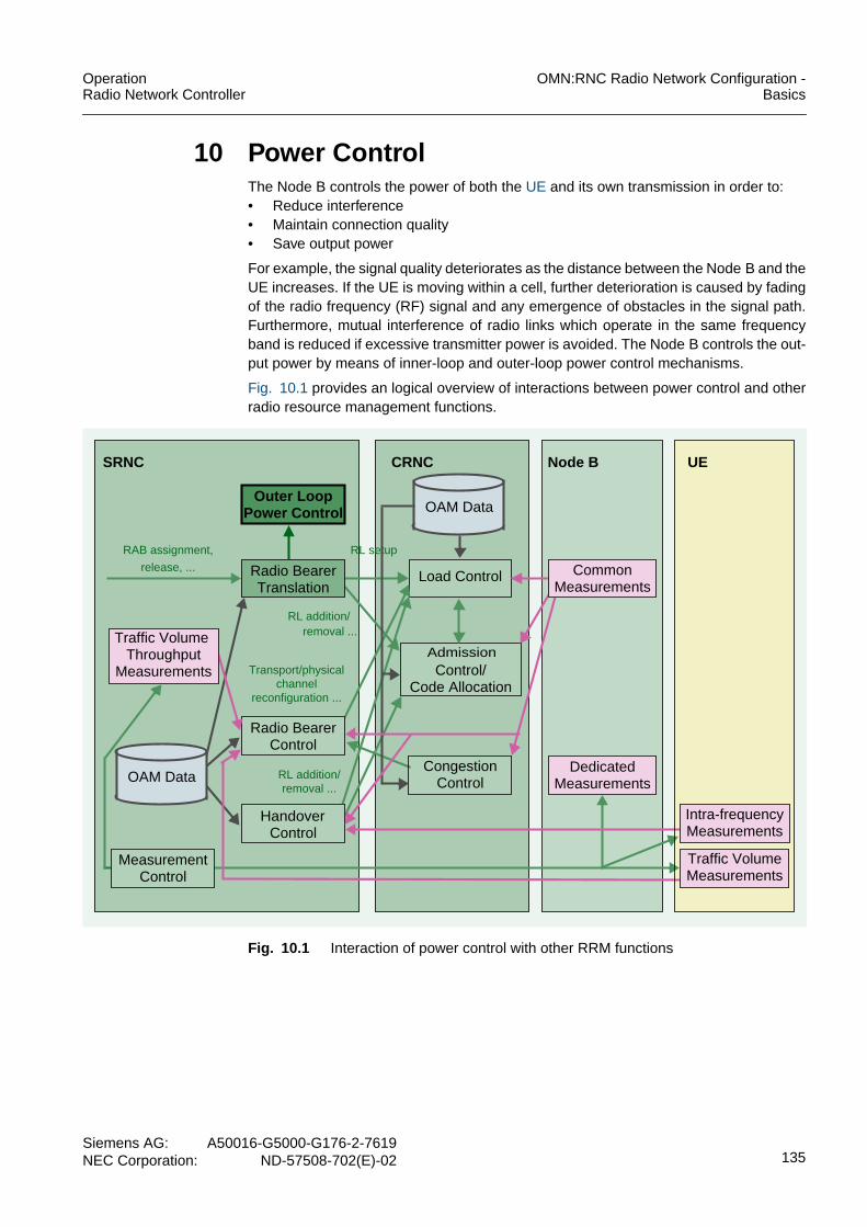
OperationRadio Network Controller
OMN:RNC Radio Network Configuration -Basics
Siemens AG: A50016-G5000-G176-2-7619NEC Corporation: ND-57508-702(E)-02 135
10 Power ControlThe Node B controls the power of both the UE and its own transmission in order to:• Reduce interference• Maintain connection quality• Save output power
For example, the signal quality deteriorates as the distance between the Node B and theUE increases. If the UE is moving within a cell, further deterioration is caused by fadingof the radio frequency (RF) signal and any emergence of obstacles in the signal path.Furthermore, mutual interference of radio links which operate in the same frequencyband is reduced if excessive transmitter power is avoided. The Node B controls the out-put power by means of inner-loop and outer-loop power control mechanisms.
Fig. 10.1 provides an logical overview of interactions between power control and otherradio resource management functions.
Fig. 10.1 Interaction of power control with other RRM functions
Outer LoopPower Control
Load Control
Admission
CongestionControl
Control/Code Allocation
SRNC CRNC Node B UE
MeasurementControl
Radio BearerTranslation
Radio BearerControl
HandoverControl
RAB assignment,
release, ...
RL setup
removal ...
Transport/physicalchannel
RL addition/
Traffic VolumeThroughput
Measurements
CommonMeasurements
DedicatedMeasurements
Intra-frequencyMeasurements
Traffic VolumeMeasurements
removal ...
reconfiguration ...
RL addition/
OAM Data
OAM Data

OMN:RNC Radio Network Configuration -Basics
OperationRadio Network Controller
136Siemens AG:A50016-G5000-G176-2-7619NEC Corporation:ND-57508-702(E)-02
Characteristics of power control are specified by:• Basic Mechanism of Power Control.
– cell iub CLI command or the GUI Cell window• Open Loop Power Control.
– cell iub CLI command or the GUI Cell window• Inner Loop Power Control (Closed loop power control).
– cell iub CLI command or the GUI Cell window– sccsr CLI command or the GUI Synchronization Configuration for Cell Setup
Request window• Outer Loop Power Control (OLPC) (Closed loop power control)
– olpc CLI command or the GUI Outer Loop Power Control window• Power Balancing
– cell iub CLI command or the GUI Cell window
For an overview of all parameters related to power control see Parameters for PowerControl. Entry point for related operation tasks is the Task List of the OMN:RNC RadioNetwork Configuration - Procedures part.
Example
cre olpc thr_upd=0.5 step_size=0.3 lowthr_sirerr=-3upthr_sirerr=3 mmfc_sirerr=0
The cre olpc CLI command specifies information on outer loop power control. Theparameters are defined once per RNC. thr_upd defines the difference between the SIRvalues of inner and outer loops that must be reached for the inner loop value to beupdated. step_size specifies the increment by which the SIR value of the outer loop isincreased if the CRC assigns this. lowthr_sirerr and upthr_sirerr define the lower andupper threshold of the SIR error. If the difference between lowthr_sirerr andupthr_sirerr is within 2.0 dB, UL OLPC may not work correctly. mmfc_sirerr specifiesthe filter coefficient for filtering SIR error measurements for event E and F.
cre cell iub cellid=1900 nodebid=190 cellid_lcl=0uarfcn=9813,10763 max_dltp=43 t_cell=2 sac=0 rac=1 lac=1901nwom=md2 atdt=mnd tmr_cspu=60 t312=1 n312=1 t313=3 n313=20 n315=1id_ura=1 tpcu=30 t302=4000 n302=3 t307=30 sc_pcpi=101pwr_pcpit=33 po_bch=-3 po_psch=-3 po_ssch=-3 dclc_utran=6 poff-set=16 pwval_max=6 t316=30 t317=180 cio=0 t300=3000 n300=2 t309=5t314=6 t315=180 sac_cbs=1900 plmn_vt=0 po_thra=3 flag_asup=offt304=1000 n304=1 t308=320 sscode=0
The cre cell iub command creates the Iub interface-related data. This commandincludes parameters to determine the initial values of the inner loop power controlinformation on a per-cell basis. max_dltp specifies the maximum power for all downlinkchannels of one cell relative to the CPICH power. pwr_pcpit indicates the total trans-mitted power of the CPICH. poffset indicates the power offset for the evaluation of themaximum downlink transmission power. pwval_max specifies the maximum powervalue.
cre dlcc cellid=1900 nodebid=190 id_cch=0 ccho_type=0 po_pch=-3po_pich=-6 sccpch_scd=0 sccpchoff=0 sccpch_ccd=4 pich_ccd=3
cre dlcc cellid=1900 nodebid=190 id_cch=1 ccho_type=1 mfachp=-1,-1 sccpch_scd=0 sccpchoff=0 sccpch_ccd=1

OperationRadio Network Controller
OMN:RNC Radio Network Configuration -Basics
Siemens AG: A50016-G5000-G176-2-7619NEC Corporation: ND-57508-702(E)-02 137
cre dlcc cellid=1905 nodebid=190 id_cch=0 ccho_type=2 mfachp=-1,-1 po_pch=-3 po_pich=-6 fach_ctch=true no_rfrm=1 peri_rfrm=10frmofs_cbs=0 sccpch_scd=0 sccpchoff=0 sccpch_ccd=1 pich_ccd=3
The dlcc CLI commands must be entered after the respective cell has been created.There can be more than one instance of dlcc within a cell. The above commands specifycommon downlink channel information for the cells with cellid=1900 and cellid=1905.id_cch uniquely identifies a common channel.
ccho_type=0 indicates that the S-CCPCH carries PCH channels and ccho_type=1indicates that the S-CCPCH carries FACH channels. If the common channel object typeccho_type is set to 2, the SCCPCH is mapped to the PCH/FACH.
po_pch/po_pich defines the difference between the PCH/PICH power and the primaryCommon Pilot Channel Transmitter (CPICH Tx) power and must only be assigned forccho_type=0 or 2.
mfachp specifies the maximum FACH power and must only be assigned forccho_type=1 or 2. mfachp consists of two values. The second value specifies the max-imum FACH power of the DTCH.
sccpch_scd indicates the DL scrambling code of the S-CCPCH and must be specifiedif ccho_type =0 . Furthermore, sccpchoff and sccpch_ccd specify the offset and theDL channelization code number for the S-CCPCH. pich_ccd=DDD indicates the DLchannelization code number for the PICH and can only be specified for ccho_type =0or 2 .
The following parameters can only be specified for ccho_type = 2 . The common trafficchannel indicator for FACH fach_ctch indicates whether or not the cell broadcastchannel is supported in the cell. no_rfrm specifies the number of radio frames in thetransmission time interval of the FACH used for CTCH (MTTI). Furthermore, peri_rfrmindicates the period of radio frames and frmofs_cbs=0 specifies the cell broadcastservice frame offset.
cre ulcc cellid=1900 nodebid=190 id_cch=0 sc_wno=0avsgn=0,1,2,3,4,5,6,7,8,9,10,11,12,13,14,15 po_aich=-4constval=-20 subch=0,1,2,3,4,5,6,7,8,9,10,11 aicht=1 aich_ccd=2prmthr=-18 pwrs=2 prmretmax=64 mmax=32 nb01min=0 nb01max=5avestr=0,0,0,0,0,0,0 aveend=15,15,15,15,15,15,15sbch_asn=1111,1111,1111,1111,1111,1111,1111factor=0.9,0.9,0.9,0.9,0.8 map_tbl=6,5,4,3,2,1,0
The ulcc CLI command must be entered after the respective cell has been created.There can only be one ulcc instance per cell. The above command specifies commonuplink channel information for the cell with cellid=190 . id_cch uniquely identifies acommon channel. sc_wno indicates the scrambling code word number, a networkplanning parameter which should be different in adjacent cells. avsgn specifies the listof available signatures for access to the RACH, see Access classes. po_aich definesthe difference between the AICH power and the primary Common Pilot ChannelTransmitter (CPICH Tx) power.
subch indicates the number of subchannels. aicht and aich_ccd specify the transmis-sion timing and the DL channelization code number for the AICH.
The constval parameter is used for the preamble initial Tx power setting. Furthermore,the following parameters are related to the determination of the RACH initial power: Thepreamble threshold prmthr , the power ramp step pwrs , the maximum retransmissioncount per cycle prmretmax , the maximum number of cycles mmax , the minimum time

OMN:RNC Radio Network Configuration -Basics
OperationRadio Network Controller
138Siemens AG:A50016-G5000-G176-2-7619NEC Corporation:ND-57508-702(E)-02
interval between cycles nb01min , and the maximum time interval between cyclesnb01max . For more information see RACH Tx Power.
avestr and aveend indicate the available signature start and end index. Whereassbch_asn indicates the assigned sub channel number. factor specifies the persistencescaling factor and map_tbl indicates the mapping table between access classes andaccess service classes.
10.1 Basic Mechanism of Power ControlA group of functions provides the power control mechanism in UL and DL for a W-CDMAsystem. Fig. 10.2 shows the functions and control items.
Fig. 10.2 Control functions and items for power control
For the DL common channels on the radio interface, the primary CPICH transmit poweris set as an absolute value (in dBm units). All other common control channel transmitpowers are set relative to the Primary CPICH. These common control channels will notuse power control. The primary CPICH transmit power shall be initially determined on acell-by-cell basis during radio network planning and optimized after site installation tests.The primary CPICH Tx power is specified by the pwr_pcpit parameter of the cell iub CLIcommand or the GUI Cell window.
Uplink power control
In a W-CDMA system, a number of UEs shares a single carrier frequency. Therefore,signals from near-by users may interfere with other users leading to an unsuccessfulsignal reception and separation.
In the UL, the “near-far effect” describes the interference between a UE that is locatedclose to the Node B and a UE that is located at the border of the cell. If both UEs transmit
UL outer loop power control
Closed Loop
Power Control Open Loop
Inner Loop
Outer Loop
RACH Tx power setting
UL DPCCH initial Tx power setting
DL DPCH initial Tx power setting
UL DPCCH/DPDCH Tx power setting
DL DPCH Tx power setting
DL power balancing
DL common channel Tx power
UL DPCCH/DPDCH Tx power setting

OperationRadio Network Controller
OMN:RNC Radio Network Configuration -Basics
Siemens AG: A50016-G5000-G176-2-7619NEC Corporation: ND-57508-702(E)-02 139
signals with the same power, the Node B receives the signals of the nearby UE with ahigh power level. The signals of the UE that is at the border of the cell, however, reachthe Node B with a low power level and interference with other signals or powerattenuation occurs.
Power control solves this “near-far effect” in UL by balancing the transmitted power ofall UEs in a cell so that all signals reach the Node B with the same power level regard-less of the distance between UE and Node B. This power control mechanism uses DLpower control signals to indicate power increase or decrease to each UE.
Downlink power control
The transmit power of the Node B per cell is shared among:• The connected UEs• The common control channels
The system capacity is directly determined by the required code power for each radioconnection, that are the UEs and the common channels.
An excessive transmit power may result in an increase of interference on adjacent cells.Therefore, power control in DL aims to maximize the system capacity by optimizing thetransmit power to a minimum level while ensuring an adequate transmission quality.
10.1.1 Radio Link Setup and Power ControlIf a UE accesses the network, the physical link is established and power control isperformed as follows:
1. The UE searches for the Synchronization Channels (SCHs) and the Common PilotChannels (CPICHs) transmitted from the Node Bs. Furthermore, the UE identifiesthe scrambling code of the Node B related to the required cell. This procedure iscalled “cell search”.
2. The UE acquires the initial transmit power and the power ramp step from the Broad-cast Channel (BCH) that is transmitted by the Primary Common Control PhysicalChannel (P-CCPCH).
3. According to the acquired system information, the UE sends a network accessrequest to the Node B by using the Random Access Channel (RACH) that is trans-mitted by the Physical Random Access Channel (PRACH).The RACH transmit power is determined based on the system information. Thepower ramping scheme is applied during the RACH transmission.
4. The UE acquires the initial transmit power from the RNC office data to set up the ULDedicated Physical Control Channel (DPCCH). Likewise, the Node B decides on theinitial transmit power for the DL DPCH.
The power control during an ongoing call consists of the following steps:
1. The Node B derives the Signalling-to-Interference-Ratio (SIR) from the DPCCH thatis sent by the UE. Based on the SIR, the Node B sends one of the following powercontrol information to the UE via DPCH (that is DPCCH/DPDCH):– increase the power– decrease the power– maintain the current level
2. According to the received power control indication, the UE changes the transmitpower and applies the new transmit power to the subsequent transmission.

OMN:RNC Radio Network Configuration -Basics
OperationRadio Network Controller
140Siemens AG:A50016-G5000-G176-2-7619NEC Corporation:ND-57508-702(E)-02
10.2 Open Loop Power ControlOpen loop power control provides a unidirectional power control mechanism that allowsthe transmitter, that is the UE in UL, to autonomously control its transmit power. No feed-back is sent by the distant end, that is the Node B in UL.
The transmitter uses open loop power control to determine its own transmit poweraccording to the propagation loss estimated from the received power.
When accessing the W-CDMA radio network, the UE uses open loop power control todetermine:• RACH Tx Power• UL DPCCH Initial Power• DL DPCCH Initial Power
Fig. 10.3 shows the open loop power control mechanism.
Fig. 10.3 Open loop power control
10.2.1 RACH Tx PowerDuring the initial network access, the UE first sets up the downlink radio link, that is thephysical link, via a cell search procedure. Afterward, the UE uses a RACH transportchannel to send a network access request to the Node B. The RACH transport channelis mapped onto the message part of a PRACH and transmitted via the PRACH.
A PRACH consists of:• One or more preambles• A message part
Each preamble contains 4096 chips. The UE transmits the preamble to the Node B priorto the message part to set up the scrambling code synchronization with a Node B. Fromthe preamble, the Node B knows the scrambling code as well as the transmission timingof the subsequent message part. Fig. 10.4 shows the PRACH structure.
Node B
UE
- Estimates propagation loss fromDL common control channel
- Calculates transmission power

OperationRadio Network Controller
OMN:RNC Radio Network Configuration -Basics
Siemens AG: A50016-G5000-G176-2-7619NEC Corporation: ND-57508-702(E)-02 141
Fig. 10.4 PRACH structure
The preamble is sent with the minimum power within the power range that is detectableby the Node B to minimize the interference on other UEs. This minimum required poweris detected by the power ramping mechanism.
Power ramping
The transmit power for the first PRACH preamble is determined by the followingprocedure:
1. The UE acquires the following system information from the BCH transmitted by theP-CCPCH:– Primary CPICH Tx power– Constant value– UL interference
2. The UE measures the Received Signal Code Power (RSCP) for the CPICH of therequired Node B.
3. The UE calculates the initial power of the preamble4. The UE sends the first preamble with the calculated power.
The initial power of the preamble is calculated by the following equation:
Preamble initial power = P-CPICH TX power (dBm) - CPICH_RSCP (dBm)+ Uplink interference (dBm) + constant value
The primary CPICH Tx power is specified by the pwr_pcpit parameter of the cell iub CLIcommand or the GUI Cell window.
The UE sends continuously preambles to the Node B until the Node B recognizes apreamble and responds via the Acquisition Indication Channel (AICH). The UE sendsthe first preamble with the initial power and continuously increases the power by apredefined ramp step. Fig. 10.5 shows the power ramping mechanism.
Preamble
Time
...
Message part
PRACH
4096chips
Preambles are sent
Data
Control signals
RACH is carriedas datauntil they are recognized
by the Node B

OMN:RNC Radio Network Configuration -Basics
OperationRadio Network Controller
142Siemens AG:A50016-G5000-G176-2-7619NEC Corporation:ND-57508-702(E)-02
Fig. 10.5 Power ramping mechanism
10.2.2 UL DPCCH Initial PowerThe UE determines the initial power of the UL DPCCH by the following procedure:
1. Acquire the DPCCH power offset from the received RRC messages, for example theRRC CONNECTION SETUP message.
2. Measure the CPICH RSCP of the required Node B.3. Calculate the UL DPCCH initial power using the following equation:
The UE transmits the first DPCCH with the calculated power. The DPCCH power offsetis set by RNC office data regardless of the distance between the UE and the Node Bwhile the CPICH RSCP measured at the UE may vary. For this reason, the DPCCHinitial power of a UE located at the cell edge tends to be higher than that of a UE locatedclose to the Node B.
Fig. 10.6 shows the process flow from the initial power determination of the UL DPCCHto the start of the inner loop power control.
... ...1 2 3 n
...... 1 2 3 n...
...1 2 3 n... Time
PR
AC
Hm
essa
gepa
rt
PreamblePreamblethreshold
Powerrampstep
Max. no of trans-missions per cycle
Max. number of cycles
Min. timebetween
Max. timebetween
two cycles two cycles Power offsetbetween themessage partand the precedingpreamble
DPCCH initial transmission power DPCCH PowerOffset dB( ) CPICH RSCP dBm( )–=

OperationRadio Network Controller
OMN:RNC Radio Network Configuration -Basics
Siemens AG: A50016-G5000-G176-2-7619NEC Corporation: ND-57508-702(E)-02 143
Fig. 10.6 Process flow for the UL DPCCH initial power setting
10.2.3 DL DPCCH Initial PowerIn the downlink, the DPCCH and DPDCH are time-multiplexed on Dedicated PhysicalChannel (DPCH). Furthermore, the DPDCH is mapped to the logical channel DCCH,that is the Dedicated Control Channel. The DPCCH initial power is determined by theoffset values PO1 to PO3 against DPDCH.
The RNC determines the initial power of the DL DPCCH by the following procedure:• Acquire the CPICH Ec/N0 measurement results from the UE via the MEASURE-
MENT REPORT message.• Calculate the DL DPDCH initial power using the following equation then include the
calculated initial power in an NBAP message, for example the RL SETUPREQUEST message.
where PDPDCH specifies the initial DPDCH power, SIRtarget the target SIR and SF thespreading factor. Margin is a fixed margin.
Afterward, the Node B sends the DPDCH with the initial power calculated by the RNC.The initial power should be within the range between the maximum and minimum trans-mit powers set by RNC, see Fig. 10.7:
Power convergence or end
Yes
of preamble transmission cycle?No
Calculates UL DPCCHinitial transmission power
Sends DPCCH power controlpreamble every 7 slots
Increases/decreases power:
step size: 1 dB
TPC= 1 -> power upTPC=-1 -> power down
Inner loop power controlcommences
DPDCH/DPCCH power offsetgain is notified to the UE
from the upper layer
DPCCH transmissioncommences
PDPDCHinitial min SIRt etarg 10 SF 2⁄( )log– Ec No⁄( )CPICH– M inarg MaxInitialPower,+[ ]=

OMN:RNC Radio Network Configuration -Basics
OperationRadio Network Controller
144Siemens AG:A50016-G5000-G176-2-7619NEC Corporation:ND-57508-702(E)-02
Fig. 10.7 Allowable range for the DPDCH initial power
The maximum/minimum Tx power, Pmax and Pmin, are specified by the followingequations:
where SIRtarget indicates the target SIR and SF the spreading factor. Delta is set to25 dB.
The power offset for determining the maximum transmit power Poffset is specified foreach cell by the poffset parameter of the cell iub CLI command or the GUI Cell window.Furthermore, the cell-specific maximum transmit power of downlink dedicated channelsMax Power value is specified by the pwval_max parameter of the same command.
Fig. 10.8 shows the process flow for the DL DPCH initial power setting.
Fig. 10.8 The process flow for the DL DPCH initial power setting
Tx Power
Pmax(Max. Tx Power)
Pmin(Min. Tx Power)
Time
Allowable range forDPDCH initial power
Pmax dB( ) MaxTxPower( ) min SIRt etarg 10 SF( )log– Poffset MaxPowervalue,+[ ]=
Pmin dB( ) MinTxPower( ) max Pmax dB( ) Delta– 35dB–,[ ]=
RNC calculates DLDPDCH initial power
Inner loop power controlcommences
UE commences DPCCHand DPDCH transmission
RNC calculates DLDPCCH initial power
Determined by PO1, PO2,and PO3 against DPDCH

OperationRadio Network Controller
OMN:RNC Radio Network Configuration -Basics
Siemens AG: A50016-G5000-G176-2-7619NEC Corporation: ND-57508-702(E)-02 145
10.2.4 Basic Concept to Calculate the Initial Values for Power ControlThis function provides the initial values for the uplink and downlink power control asspecified in the corresponding NBAP and RRC procedures. A description of thealgorithm used to calculate these parameters is provided below.
10.2.4.1 Parameters Calculated in the SRNCParameters calculated in the SRNC are:• DPCCH power offset• Initial UL SIR target• PO1, PO2, PO3, TPC step size, power control algorithm• Initial power of the DPDCH
DPCCH power offset
The power offset parameter for the DPCCH is defined per RNC and is used by the UEto calculate the initial power of the DPCCH, for more information see 3GPP TSG RANWG2: RRC Protocol Specification, TS 25.331:
Power initial for DPCCH := Power offset - CPICH RSCP measured in the UE
Initial UL SIR target
The initial UL SIR target value is specified by tables which map the BLER to the SIR.These tables differ depending on the services/applications.
P01, P02, P03, TPC step size, power control algorithm
Fixed values are specified for the parameters PO1, PO2, PO3, TPC step size, and thepower control algorithm. These parameters are not configurable by the operator.
Initial power of the DPDCH
The DL initial power value of the DPDCH is calculated in the SRNC and transmittedtogether with the UL SIR target to the CRNC via RNSAP, for more information see 3GPPTSG RAN WG3: UTRAN Iur Interface RNSAP Signaling, TS 25.423.
The initial power of the dedicated channel can be determined by
| SIROLPC,target - SIRCLPC,target | > Update_threshold
The DL Power indicates a power level relative to the primary CPICH power configuredin a cell, for more information see 3GPP TSG RAN WG3: NBAP Specification,TS 25.433:
SIRtarget denotes the DL SIR target that depends on the application in dB. (Ec/I0)CPICHis measured by the UE in dB and reported to the RNC. SF denotes the spreading factor.The margin and the maximum initial power inipwmax are specified once per RNC in dB.The maximum initial power is specified relative to CPICH and is less than or equal to15 dB.
The office data for the DL Ec/I0 is used if the (Ec/I0)CPICH is not available, for example inthe case of channel-type switching from Cell_FACH to Cell_DCH for DL activity.
PDPDCHinitial median SIRtarget 10SF2
------- Ec
I 0
------
CPICHmargin inipwmax 35dB–,,+–log–
=

OMN:RNC Radio Network Configuration -Basics
OperationRadio Network Controller
146Siemens AG:A50016-G5000-G176-2-7619NEC Corporation:ND-57508-702(E)-02
10.2.4.2 Parameters Calculated in the CRNC/DRNCParameters calculated in the CRNC/DRNC are:• Initial power of the pilot channel• Initial power of the secondary CCPCH• Initial power of the DPDCH and UL SIR target• Max/min power of the DPDCH• Max/min UL SIR
Initial power of the pilot channel
The initial power of the pilot channel is sent to the Node B and is operator-specific.
Initial power of the secondary CCPCH
The power of the secondary CCPCH is set by the network.
Initial power of the DPDCH and UL SIR target
The initial power of the DPDCH is calculated in the SRNC and sent together with the ULSIR target to the CRNC or DRNC. If the initial power is out of the range calculated below,the DRNC sends the minimum and maximum DPDCH transmission power via RNSAPRADIO LINK SETUP/ADDITION RESPONSE message to the SRNC.
If these values are not supported via RNSAP, the initial DL transmission power, whichis a relative value to the CPICH power, is calculated in the DRNC according to
Maximum/minimum power of the DPDCH
The Maximum/minimum power of the dedicated channel depends on the cell and theNode B capabilities. The DL power indicates a power level relative to the primary CPICHpower configured in a cell, for more information see 3GPP TSG RAN WG3: NBAPSpecification, TS 25.433.
SIRtarget denotes the initial SIR target in dB. (Ec/I0)CPICH is reported via RNSAP in dBsince the UL SIR target is not reported. SF denotes the spreading factor. The marginand the maximum initial power inipwmax are specified once per RNC in dB. Themaximum initial power is specified relative to CPICH and is less than or equal to 15 dB.If the UL SIR target is not sent via RNSAP from the SRNC, the office data value is usedin the DRNC instead. This value is then sent in the RL SETUP RESPONSE message tothe SRNC.
where ∆ is the RNC specific power range between maximum and minimum power andPoffset is the power offset. The Max power value is a cell-specific offset to the CPICHpower and indicates the cell specific maximum DL transmission power of a dedicatedchannel. It has to be less than or equal to 15 dB. The minimum value corresponds to the
PDPDCHinitial median SIRtarget 10SF2
------- Ec
I 0
------
CPICHmargin inipwmax 35dB–,,+–log–
=
Pmax dB( ) min SIRtarget 10 SF( )log Poffset Maxpowervalue,+–( )=
Pmaxin dB( ) max Pmax dB( ) ∆ 35dB–,–( )=
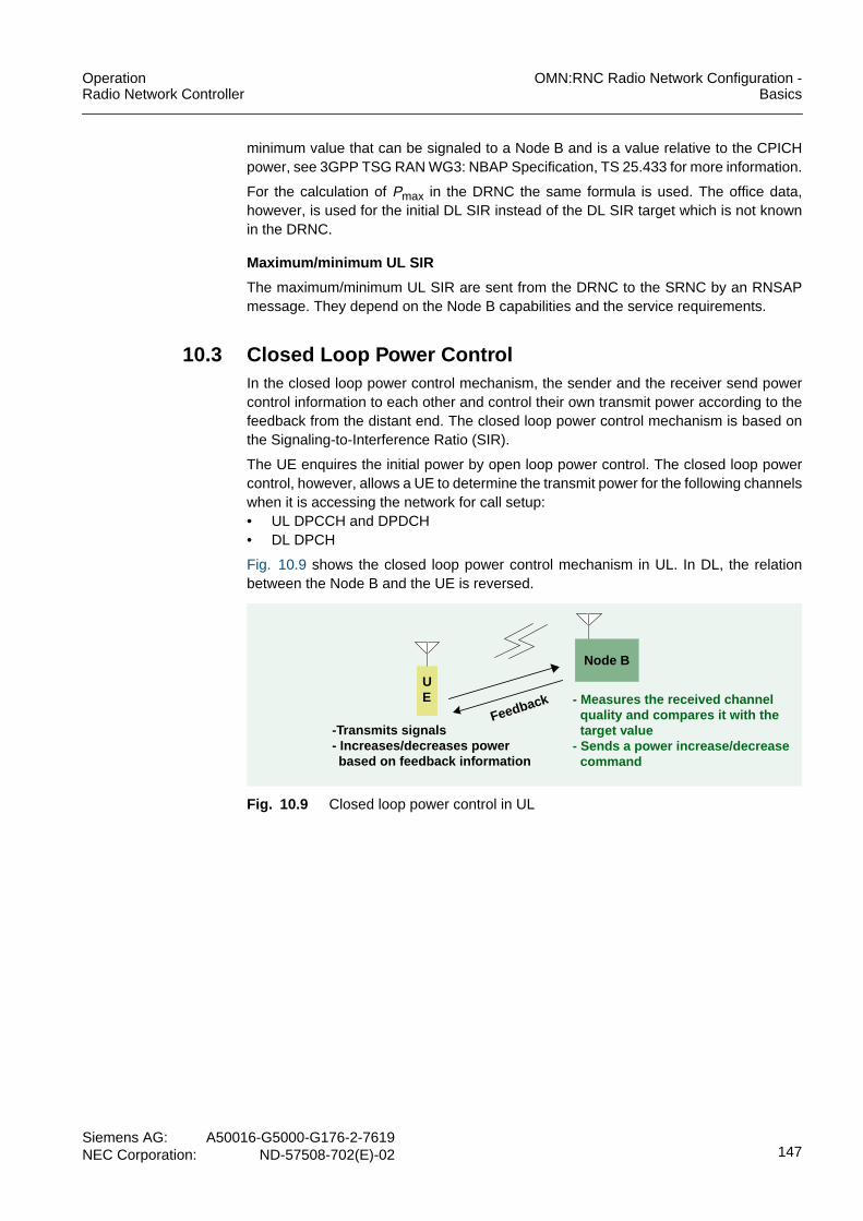
OperationRadio Network Controller
OMN:RNC Radio Network Configuration -Basics
Siemens AG: A50016-G5000-G176-2-7619NEC Corporation: ND-57508-702(E)-02 147
minimum value that can be signaled to a Node B and is a value relative to the CPICHpower, see 3GPP TSG RAN WG3: NBAP Specification, TS 25.433 for more information.
For the calculation of Pmax in the DRNC the same formula is used. The office data,however, is used for the initial DL SIR instead of the DL SIR target which is not knownin the DRNC.
Maximum/minimum UL SIR
The maximum/minimum UL SIR are sent from the DRNC to the SRNC by an RNSAPmessage. They depend on the Node B capabilities and the service requirements.
10.3 Closed Loop Power ControlIn the closed loop power control mechanism, the sender and the receiver send powercontrol information to each other and control their own transmit power according to thefeedback from the distant end. The closed loop power control mechanism is based onthe Signaling-to-Interference Ratio (SIR).
The UE enquires the initial power by open loop power control. The closed loop powercontrol, however, allows a UE to determine the transmit power for the following channelswhen it is accessing the network for call setup:• UL DPCCH and DPDCH• DL DPCH
Fig. 10.9 shows the closed loop power control mechanism in UL. In DL, the relationbetween the Node B and the UE is reversed.
Fig. 10.9 Closed loop power control in UL
Node B
UE
-Transmits signals- Increases/decreases powerbased on feedback information
Feedback - Measures the received channelquality and compares it with thetarget value
- Sends a power increase/decreasecommand

OMN:RNC Radio Network Configuration -Basics
OperationRadio Network Controller
148Siemens AG:A50016-G5000-G176-2-7619NEC Corporation:ND-57508-702(E)-02
Closed loop power control consists of two stages:• Inner Loop Power Control
The inner loop aims at controlling the UE output in short intervals, that is by a slotcycle of 0.667 msec. Therefore, it is also known as “Fast Closed Loop”.The inner loop is implemented at the Layer 1, that is the physical layer. It performsfeedback control in a way that keeps the received SIR closer to the target SIR.
• Outer Loop Power Control (OLPC)The outer loop controls the SIR in rather long intervals, for example some 100 msecor seconds.The outer loop is implemented by the Layer 3 RRC protocol. The outer loopestimates a target average Block Error Rate (BLER) and sets an SIR for maintainingthe target.
The SIR varies due to:– Multipath propagation environment changes– Dependency of the UE velocityThe set SIR is then used in the inner loop as the SIR target when performing feed-back control.
Fig. 10.10 shows the configuration of the closed loop power control in the uplink.
Fig. 10.10 Closed loop power control configuration (UL)
10.3.1 Inner Loop Power ControlInner loop power control is set up between the Node B and the UE and takes a pre-defined signal-to-interference ratio (SIR) as input (target SIR). It is performed every timeslot. The receiver, that is the Node B in the uplink, first measures the SIR of the receivedsignals and compares the measured value with the target SIR. Based on the compari-son result, the receiver sends a power increase/decrease command to the sender, thatis the UE in the uplink. Due to this command, the sender can adjust the quality of thereceived signal closer to the target.
The inner loop power control determines:• UL DPCCH/DPDCH Tx Power Setting• DL DPCH Tx Power Setting
Spread Power Amp
RAKEReceiver
Despread
UE Node B RNC
Despread
SIR Meas
Compare
Transmit PCGeneration
Spread
Compare
QualityMeas
TargetSIR
TargetQuality
Inner Loop
Outer Loop
UL
DL

OperationRadio Network Controller
OMN:RNC Radio Network Configuration -Basics
Siemens AG: A50016-G5000-G176-2-7619NEC Corporation: ND-57508-702(E)-02 149
10.3.1.1 UL DPCCH/DPDCH Tx Power SettingFig. 10.11 shows the operational sequence of inner loop power control in the uplink.
Fig. 10.11 Inner loop power control operational sequence (UL)
The Node B:• Measures the received SIR of the UL DPCCH pilot field.• Compares the measured SIR with the SIR target.• Generates a Transmit Power Control (TPC) command using the following algorithm
and transmits it in the TPC field of a DL DPCH based on the comparison result.
where SIRest specifies the measured SIR and SIRtarget the target SIR.
Since the TPC command is generated per time slot, the inner loop power control canefficiently respond to the fluctuations in the propagation paths.
Measures SIR
Compares withtarget
Sends TPCcommand
DPCCH
Pilot
TFCI
FBI TPC
DPCH
DPDCHDPCCH
DataTPC
TPCFBI
TFCI
TFCIPilot
Pilot
DPCCHIncreases/
decreases power
TFCI: Transport Format Combination Indicator
Node BUE
FBI: Feedback InformationTPC: Transmit Power Control
SIRest SIRt etarg TPC→> 1–=
SIRest SIRt etarg TPC→< 1=

OMN:RNC Radio Network Configuration -Basics
OperationRadio Network Controller
150Siemens AG:A50016-G5000-G176-2-7619NEC Corporation:ND-57508-702(E)-02
The UE:• Determines whether to increase or decrease the power of the next uplink transmis-
sion (DPCCH/DPDCH) according to the received TPC command:
• Applies the algorithm and calculates the amount of power increase/decrease takinginto account the number of paths set up at the UE:– One path: The UE increases or decreases the power by ∆DPCCH in ∆TPC steps
according to the TPC command generated per time slot (1).– Multiple paths (in soft handover cases): The UE receives TPC commands from
multiple cells. The TPC commands of the same slots received from all theinvolved Node Bs are combined to deliver the amount of power increase/decrease(2).
The transmit power after change may not exceed the lower value between themaximum UE power and the maximum power given by the upper layer. The step ofpower increase/decrease is fixed to 1 dB.
• Increases or decreases the transmit power and transmits signals.Assuming no changes in the gain factor, the DPCCH and DPDCH power are bothincreased or decreased by the same amount.
Fig. 10.12 shows the process flow for the determination of the UL DPCCH/DPDCHpower.
TPC 1 Increase power→=
TPC 1– Decrease power→=
∆DPCCH ∆TPC TPCcmd×= 1( )
TPCcmd γ W 1 W 2, …Wn,( )= 2( )

OperationRadio Network Controller
OMN:RNC Radio Network Configuration -Basics
Siemens AG: A50016-G5000-G176-2-7619NEC Corporation: ND-57508-702(E)-02 151
Fig. 10.12 UL DPCCH/DPDCH power determination by inner loop power control
UE in soft handover?
Yes
No
Node B estimates SIR ofUL DPCCH pilot
Compares measured SIRwith SIR target
Generates TPC command
SIRest > SIRtarget -> TPC =-1SIRest < SIRtarget -> TPC =1
UE combines TPC commandsof multiple paths by:
Calculates power increase
and transmits it to the UE:
TPC_cmd=γ (W1, W2, ... Wn)Applies:TPC = 1 -> Power increaseTPC = -1 -> Power decreaseStep size: 1 dB
TPC = ?
TPC = 1
TPC = -1
∆DPDCH = ∆TPC X TPC_cmdCalculates power decrease∆DPDCH = ∆TPC X TPC_cmd
Exceeds maximumUE power?
Yes
No
Makes no changesUE increase power

OMN:RNC Radio Network Configuration -Basics
OperationRadio Network Controller
152Siemens AG:A50016-G5000-G176-2-7619NEC Corporation:ND-57508-702(E)-02
10.3.1.2 DL DPCH Tx Power SettingFig. 10.13 shows the operational sequence of inner loop power control in the downlink.
Fig. 10.13 Inner loop power control operational sequence (DL)
The DPCCH and DPDCH are time multiplexed on the DPCH when transmitted over theradio interface in the downlink. Therefore, an increase or decrease of the DPCH poweraffects both the DPCCH and DPDCH.
The UE:• Generates a Transmit Power Control (TPC) command based on the measured SIR,
SIRest, and the target SIR, SIRtarget.
If multiple paths are set up (during a soft handover), the UE measures the SIR of alldownlink branches and compares the measured SIRs with the SIR target.– All the measured SIR values are below the SIR target: The UE generates TPC = 1
(power increase)– One or more measured SIR values exceeds the SIR target: The UE generates
TPC = -1 (power decrease).
• Sends the TPC command.The UE generates the TPC command per time slot and transmits it in the firsteffective TPC field of the UL DPCCH.
Measures SIR
Compares withtarget
Sends TPCcommand
DPCCH
Pilot FBI TPC
DPCH
DPDCHDPCCH
DataTPC
TFCI
TFCIPilot
Increases/decreases power
TFCI: Transport Format Combination Indicator
Node BUE
FBI: Feedback InformationTPC: Transmit Power Control
DPCH
DPDCHDPCCH
DataTPC TFCIPilot
SIRest SIRt etarg TPC→> 1–=
SIRest SIRt etarg TPC→< 1=

OperationRadio Network Controller
OMN:RNC Radio Network Configuration -Basics
Siemens AG: A50016-G5000-G176-2-7619NEC Corporation: ND-57508-702(E)-02 153
The Node B:• Determines whether to increase or decrease the power according to the received
TPC command:
• Applies the following algorithm and calculates the amount of power increase/de-crease. The step size is fixed to 1 dB.During a soft handover, TPC errors may arise at the involved Node Bs and cause apower drift between the radio links. For information on how to improve theperformance of inner loop power control see Power Balancing.
• Increases or decreases the transmit power and transmits signals.The power increase/decrease is applied to both the DPCCH and DPDCH. TheDPDCH power after the change may not be outside the range between themaximum and minimum transmit powers set by the RNC.
where Pmax and Pmin specify the maximum/minimum Tx power, SIRtarget the target SIR,and SF the spreading factor. Delta is set to 25 dB.
The power offset for determining the maximum transmit power Poffset is specified foreach cell by the poffset parameter of the cell iub CLI command or the GUI Cell window.Furthermore, the cell-specific maximum transmit power of downlink dedicated channelsMax Power value is specified by the pwval_max parameter of the same command.
Fig. 10.12 shows the process flow for the determination of the DL DPCH power.
TPC 1 Increase power→=
TPC 1– Decrease power→=
∆DPCCH ∆TPC TPCcmd×=
Pmax dB( ) min SIRt etarg 10 SF( )log– Poffset MaxPowervalue,+[ ]=
Pmin dB( ) max Pmax dB( ) Delta– 35dB–,[ ]=

OMN:RNC Radio Network Configuration -Basics
OperationRadio Network Controller
154Siemens AG:A50016-G5000-G176-2-7619NEC Corporation:ND-57508-702(E)-02
Fig. 10.14 DL DPCH power determination by inner loop power control
UE in soft handover?
Yes
No
Increase power
All measured SIRs
Decrease power
Within DPDCH transmissionpower range?
Yes
No
No change
Measures SIR of allDL branches
Compares measured SIRs
SIRest > SIRtarget -> TPC =-1SIRest < SIRtarget -> TPC =1
with target SIRs
Measures SIR of theconnected DL branch
Compares measured SIRs
SIRest > SIRtarget -> TPC =-1SIRest < SIRtarget -> TPC =1
with target SIRs
Measured SIRs< target? < target?
No
YesNo
TPC = 1TPC = -1TPC = 1
Calculate power increase/decrease∆DPDCH = ∆TPC X TPC_cmd
Node B power changeavailable?
No
No change
Increase/decrease power
Yes
Yes

OperationRadio Network Controller
OMN:RNC Radio Network Configuration -Basics
Siemens AG: A50016-G5000-G176-2-7619NEC Corporation: ND-57508-702(E)-02 155
10.3.2 Outer Loop Power Control (OLPC)Outer loop power control (OLPC) maintains a predefined connection quality in terms ofblock error rate by setting the target of the inner closed-loop power control appropriately.The SIR is kept at its optimum value, which serves to maximize system capacity and tominimize power consumption in the hardware at both ends of the connection. Further-more, interference with other radio links that share the same cell and frequency channelis kept to a minimum.
The process of outer loop power control includes:• The estimation of the target average BLER from the received signal quality
measured over a rather long time interval.• The setting of the SIR to maintain this target
Outer loop power control is performed for each Dedicated Channel and the set SIR isthen used in the Inner Loop Power Control mechanism as the SIR target when perform-ing feedback control. For FDD radio links, the OLPC function itself is located in theSRNC.
This section provides information on UL outer loop power control. DL outer loop powercontrol is performed in the UE and not subject of this manual.
Fig. 10.15 shows the determination of the UL target SIR by outer loop power control.
Fig. 10.15 UL target SIR determination by outer loop power control
SIR error specifies the offset between the target SIR currently used in the closed looppower control mechanism and the average SIR measured for a specified interval. Theouter loop power control is active as long as SIR error remains within a predefinedrange.
Node BUE SRNC
Updates target SIRfor inner looppower control
UL communication channels
Measures BLER ofUL communications
channel data streams
Updates target SIRusing CRC-based
algorithm
When the specifiedcriterion is true,
notifies the target SIRupdate to the Node B
Inactivates outer looppower control
due to SIR error
Inner loop power control
Outer loop power control
SIR error outsideallowed rangeSIR error within
allowed range
DCH: Target SIR
*) NBAP: RADIO LINK SETUP REQUESTNBAP: RADIO LINK RECONFIGURATION PREPARE
NBAP messages *)

OMN:RNC Radio Network Configuration -Basics
OperationRadio Network Controller
156Siemens AG:A50016-G5000-G176-2-7619NEC Corporation:ND-57508-702(E)-02
The RNC
1. Measures BLER of the uplink communications channels and estimates a targetBLER accordingly.
2. Determines a target SIR based on the Cyclic Redundancy Check (CRC) evaluation.For more information on the algorithm see Basic Mechanism of Uplink Outer LoopPower Control. The updated target SIR ought to be inside the range between themaximum and minimum SIRs set by RNC.
3. Compares the target SIR updated by the outer loop power control mechanism withthe SIR that is currently used in the closed loop power control mechanism. If the off-set exceeds the update threshold, the RNC sends the target SIR update to theNode B via the RADIO LINK SETUP REQUEST or RADIO LINK RECONFIGURA-TION PREPARE messages.
If the SIR error is outside the range limited by the maximum and minimum SIR errors,the outer loop power control mechanism is disabled. Outer loop power control resumeswhen the SIR error is within the limits again.
Fig. 10.16 shows the process flow for UL outer loop power control.
Fig. 10.16 UL outer loop power control
SIR error within
Yes
No
RNC sets target SIR andnotifies the Node B
CRC = ?
allowed range?
Disable outer looppower control
Bad
Raise target SIR
Good
Lower target SIR
Update thresholdexceeded?
No
Do not send updatedtarget SIR
Send updated target SIRto the Node B

OperationRadio Network Controller
OMN:RNC Radio Network Configuration -Basics
Siemens AG: A50016-G5000-G176-2-7619NEC Corporation: ND-57508-702(E)-02 157
10.3.2.1 Basic Concept of Outer Loop Power ControlOuter loop power control is performed in the RNC and is located on the Diversity Hand-over Trunk (DHT) which is associated with a UE. DHT modules terminate the Iub/Iurframe protocol for dedicated channels, see Fig. 10.17.
OLPC is based on the CRC information of the reference bearer. A new OLPC referencebearer is also selected at DCH setup and RAB assignment.
When using dedicated channels, there is one DHT resource for the RRC connection anda DHT resource for each RAB that is required. If several DHT resources are associatedwith a UE, the reference bearer (DHT ID) for the OLPC is selected according to thefollowing hierarchy (highest first):
UDI -> AMR -> PS Conversational -> Streaming (CS/PS) -> PS Interactive/Background-> SRB
Whenever an NBAP: RADIO LINK SETUP REQUEST or NBAP: RADIO LINKRECONFIGURATION PREPARE message is sent, a UL SIR target is included unlessswitching to common channels occurs.
If the reference bearer changes, the OLPC is initialized with all of the following:• The corresponding RAB parameters (BLER target)• The maximum of the old SIR target values determined by the previous reference
bearer• The values held in the OAM database for the new bearer.
Fig. 10.17 OLPC: functional entities and how they interact
OLPC
SIRErrorEvaluation
ReferenceBearerSelection
DHT Module
CLP
SIRCLPC,targetSIROLPC,target
SIRCLPC,targetSIROLPC,target
BLERtargetError_flag
DCH Setup
RAB Assignm.Averaging,Preprocessing
UL DPCH
DL DPCH+
-
SIRmeas.
CRCcheckCRC Indicator 1
...CRC Indicator n
SIRCLPC,target
Dedicated meas. report SIR error
RNCNBAP
Iub / Iur Frame Protocol
Node B
TPC

OMN:RNC Radio Network Configuration -Basics
OperationRadio Network Controller
158Siemens AG:A50016-G5000-G176-2-7619NEC Corporation:ND-57508-702(E)-02
10.3.2.2 Basic Mechanism of Uplink Outer Loop Power ControlThe uplink outer loop power control receives a platform measurement relating to theCyclic Redundancy Check (CRC) of the transmitted block as the input measurementparameter from the user frame protocol. In response to this input parameter it generatesa new UL SIR target value, which is then transmitted back to the Node B via the Iub andIur control frame protocol. Furthermore, the outer loop power control needs a qualitytarget (from radio bearer translation) and certain limits for the UL SIR target via theRNSAP radio link setup/addition response. Fig. 10.18 shows the interactions of uplinkouter loop power control.
Fig. 10.18 Interactions of uplink outer loop power control
The stable and well-known IS-95 power control algorithm is used as the basis for theouter loop power control:
1. The SIROLPC,target of a dedicated transport channel is raised by ∆ dB if a block erroroccurs.
2. The SIROLPC,target is reduced by ∆ * BLERtarget / (1 - BLERtarget ) if the frame isreceived correctly.
Consequently, the algorithm can be described as follows:
where SIROLPC,target specifies the target SIR set by outer loop power control, ∆ indicatesthe power change step, and BLERtarget is the target block error rate.
The step size ∆
The step sizes have been chosen such that in the long-term the target frame error rateBLERtarget is reached:• Each step ∆ in upward direction occurs with the probability BLERtarget• Each step ∆ in downward direction occurs with the probability 1-BLERtarget
Each step ∆ has the step size (∆ * BLERtarget)/(1 - BLERtarget).
Iub/Iur Uplink User FrameProtocol: CRC Indicator
SRNCDynamicDatabase
O&MDatabase
UplinkOuter Loop
Power Control
RNSAP:Radio Link Setup/Addition Response
Iub/Iur Downlink User FrameProtocol: Uplink Eb/No target
SIROLPC target,
SIROLPC target, ∆+ 1( )
SIROLPC target,∆ BLERtarget⋅1 BLERtarget–------------------------------------– 2( )
=

OperationRadio Network Controller
OMN:RNC Radio Network Configuration -Basics
Siemens AG: A50016-G5000-G176-2-7619NEC Corporation: ND-57508-702(E)-02 159
The value of the step size ∆ depends on the bearer type and is defined by a scalingfactor and the step_size parameter which is specified by the olpc CLI command or theGUI Outer Loop Power Control window:
∆ = step_size * scaling factor
The scaling factor is defined within office data once per RNC for each bearer type(accounting for the number of transport blocks), see Tab. 10.1. These values can notbe configured by the operator.
Default value Service type
1 DCCH 13.6k
1 DCCH 3.4k
0,5 CS UDI 64k
0,5 CS UDI 28.8k
1 CS UDI 32k
1 PS BE 8k
0,5 PS BE 16k
0,5 PS BE 32k
0,25 PS BE 64k
0,1 PS BE 128k
0,1 PS BE 144k
0,5 CS UDI 64k + PS BE 8k
0,5 CS UDI 64k + PS BE 64k
1 AMR
1 AMR + PS BE 0k
1 AMR + PS BE 8k
1 AMR + PS BE 32k
1 AMR + PS BE 64k
0,5 AMR + CS UDI 64k
1 PS Streaming 8k + PS BE 8k
1 PS Streaming 16k + PS BE 8k
0,5 PS Streaming 32k + PS BE 8k
1 CS Streaming 14.4k
0,5 CS Streaming 28.8k
0,25 CS Streaming 57.6k
1 PS Conv 8k + PS BE 8k
0,5 PS Conv 16k + PS BE 8k
Tab. 10.1 Scaling factor for OLPC

OMN:RNC Radio Network Configuration -Basics
OperationRadio Network Controller
160Siemens AG:A50016-G5000-G176-2-7619NEC Corporation:ND-57508-702(E)-02
The MRC rounds up the calculated value of ∆ to the first decimal place. The result isused to calculate the SIROLPC,target.
Maximum/minimum SIR target values
The SIR target should remain between the maximum and the minimum SIR targetvalues denoted by SIRtarget,max and SIRtarget,min which results in
where
SIRtarget,max = initial SIR target + Max UL SIR offset
and
SIRtarget,min = initial SIR target + Min UL SIR offset
Via the Iur interface, SIRmax and SIRmin could be notified to the SRNC by the DRNC.The DRNC applies the UL SIR target notified by SRNC or the default value of the InitialUL SIR within the office data.
Update of the target SIR for inner loop power control
The SIR target changes with each cyclic redundancy check. Since there are 4 TBs perTTI for PS64 kbit/s bearers, it may happen that the SIR target increases 4 * ∆ times perTTI.
If the SIR target needs to be increased, the algorithm provides for a rapid adjustment.This serves to prevent data losses, for example if an obstacle enters the signalpropagation path. In order to limit the volume of signaling traffic, new target SIR valuesare only sent to the inner loop power control if the difference between the old and newvalues exceeds the threshold value thr_upd . This threshold value is specified by theolpc CLI command or the GUI Outer Loop Power Control window.
The SIR target is signaled to the closed loop power control (CLPC) in the Node B if thefollowing inequation is satisfied:
| SIROLPC,target - SIRCLPC,target | > Update_threshold
where SIROLPC,target denotes the SIR target evaluated by the outer loop power controland SIRCLPC,target denotes the SIR target used by the closed loop power control. If theabove equation is satisfied, the target of the closed loop power control is set to the targetof the outer loop power control:
SIRCLPC,target = SIROLPC,target
This implies that the new target of the closed loop power control is sent via the Iub/Iurframe protocol from the RNC to the Node B.
SIR error is outside the specified range
The maximum and minimum SIR targets are:• SIRmax = Initial UL SIRtarget + Max UL SIR offset
Note: If Max UL SIR offset is a negative value, then the RNC replaces it with thevalue of “0”
SIROLPC target,
min SIROLPC target, ∆ SIRtarget max,,+( )
max SIROLPC target,∆ BLERtarget⋅1 BLERtarget–------------------------------------ SIRtarget min,,–
=

OperationRadio Network Controller
OMN:RNC Radio Network Configuration -Basics
Siemens AG: A50016-G5000-G176-2-7619NEC Corporation: ND-57508-702(E)-02 161
• SIRmin = Initial UL SIRtarget + Min UL SIR offsetNote: If Min UL SIR offset is a positive value, then the RNC replaces it with the valueof “0”
If the SIR error is outside the range limited by the maximum and minimum SIR errors,the outer loop power control mechanism is disabled. Outer loop power control resumeswhen the SIR error is within the limits again:
Since the Initial UL SIR target varies according to the bearer type, the derived(SIRmax, SIRmin) are bearer specific. Tab. 10.2 shows the initial value of SIR target atthe setup of a new bearer.
SIRerror SIR Measured value( ) SIRCLPC t etarg,–=
SIRerror min, SIRerror SIRerror max, Closed loop power control enabled→< <
SIRerror SIRerror min,< o r SIRerror SIRerror max, Closed loop power control endisabled→>
Service type Type and range Default value Operator-configurable
DCCH 3.4 kbit/s -8.2…17.3 dBin step of 0.1 dB
6.0 dB No
DCCH 13.6 kbit/s 5.0 dB No
UDI 28.8 kbit/s 6.0 dB No
UDI 32 kbit/s 6.0 dB No
UDI 64 kbit/s 6.5 dB No
UDI 64 kbit/s + PS 8 kbit/s 6.5 dB No
UDI 64 kbit/s + PS 64 kbit/s 8.5 dB No
PS 8 kbit/s 3.0 dB No
PS 16 kbit/s 4.0 dB No
PS 32 kbit/s 6.0 dB No
PS 64 kbit/s 5.5 dB No
PS 128 kbit/s 8.5 dB No
PS 144 kbit/s 8.5 dB No
PS 384 kbit/s 8.0 dB No
AMR 12.2 kbit/s 3.0 dB No
AMR + PS 0 kbit/s 3.0 dB No
AMR + PS 8 kbit/s 3.0 dB No
AMR + PS 32 kbit/s 5.0 dB No
AMR + PS 64 kbit/s 6.5 dB No
Tab. 10.2 Initial UL SIR target parameters

OMN:RNC Radio Network Configuration -Basics
OperationRadio Network Controller
162Siemens AG:A50016-G5000-G176-2-7619NEC Corporation:ND-57508-702(E)-02
Event triggered reporting of SIR error
At the edge of the coverage area, the SIR can be smaller than the target SIR and manyblock errors can occur even if the UE transmits with its maximum transmission power.An increased target SIR, however, has no effect on the number of block errors becauseit cannot be reached due to the power limitation of the UE. A similar effect occurs whenthe lower limit of the power control range is reached which is not as severe because thetarget SIR can be raised rapidly if necessary.
Instead of the target SIR, the event-triggered reporting of the SIR_error is used toreduce the signaling load on the Iub interface and the processing load in the RNC:
SIRerror = SIR - SIRCLPC,target
The dedicated measurement report for the SIR_error terminates in the CLP of theCCPM module. The CLP evaluates the SIR_error reported by the Node B by comparingthe lower and upper thresholds of SIR_error. If necessary, it reports an error viaerror_flag to the OLPC algorithm on the DHT module.
The reporting is based on measurement events E and F:• Measurement event E :
– Threshold1eventE = SIR_error_max– Threshold2eventE = max [SIRerror,min, SIRerror, max - 1.0 dB]
• Measurement event F :– Threshold1eventF = SIR_error_min– Threshold2eventF = min [Threshold2eventE, SIRerror,min + 2.0 dB]
The difference between SIRerror,max and SIRerror,min must be greater than 2 dB, other-wise OLPC may not work correctly. A measurement hysteresis time of 80 ms is used forboth measurements.
The lower and upper thresholds of SIR_error, lowthr_sirerr and upthr_sirerr , arespecified by the olpc CLI command or the GUI Outer Loop Power Control window. Themeasurement filter coefficient for filtering SIR error measurements mmfc_sirerr is
AMR + UDI 64 kbit/s -8.2…17.3 dBin step of 0.1 dB
6.5 dB No
CS ST 14.4 kbit/s 5.0 dB No
CS ST 28.8 kbit/s 5.0 dB No
CS ST 57.6 kbit/s 6.0 dB No
PS ST 8 kbit/s + PS 8 kbit/s 3.5 dB No
PS ST 16 kbit/s + PS 8 kbit/s 6.5 dB No
PS ST 32 kbit/s + PS 8 kbit/s 5.5 dB No
PS CO 8 kbit/s + PS 8 kbit/s 5.5 dB No
PS CO 16 kbit/s + PS 8 kbit/s 4.0 dB No
HS-DPDCH 6.0 dB No
ST: StreamingCO: Conversational
Service type Type and range Default value Operator-configurable
Tab. 10.2 Initial UL SIR target parameters

OperationRadio Network Controller
OMN:RNC Radio Network Configuration -Basics
Siemens AG: A50016-G5000-G176-2-7619NEC Corporation: ND-57508-702(E)-02 163
specified by the olpc CLI command or the GUI Outer Loop Power Control window. Formore information see Higher Layer Filtering.
A radio link set for which the measurements were not available is considered as “good”during the OLPC status evaluation, see Tab. 10.3.
MRC re-evaluates the OLPC status and decides whether to switch OLPC ON/OFF or donothing after a soft handover, inter-frequency handover and the dedicated measure-ment failure indication procedure, see Tab. 10.4.
*Note: Re-evaluate OLPC status after the soft handover branch deletion:– Stop OLPC if there is no remaining “good” RL set, or– Keep OLPC Status as “ON” if at least 1 radio link set is “ON” or “INVALID”.
Please note that a new Node B is initialized with the maximum value of the current SIRtarget and the initial SIR target if the old OLPC status is OFF.
Dedicated measurement event E and event F are initiated after the RRC procedure iscompleted, preferably in parallel to the RRC measurements.
The DHT is started with OLPC switched to “ON” after the completion of the radio linksetup procedure in the event of:• RRC connection setup• Channel-type switching from common to dedicated channels• RAB setup from common to dedicated channels• RRC connection reestablishment
RLS OLPC status OLPC status
At least one RLS All RLS
ON - ON
INVALID - ON
- OFF OFF
Tab. 10.3 OLPC status evaluation
Procedure Old OLPC status New OLPC status Actions
Soft handoverbranch addition
ON ON -
OFF ON Switch OLPC ON
Soft handoverbranch deletion
ON ON -*
OFF Switch OLPC OFF
OFF OFF -
Inter-frequencyhandover
ON ON -
OFF ON Switch OLPC ON
Dedicatedmeasurementfailure indication
ON ON -
OFF ON Switch OLPC ON
Tab. 10.4 OLPC status re-evaluation after handover

OMN:RNC Radio Network Configuration -Basics
OperationRadio Network Controller
164Siemens AG:A50016-G5000-G176-2-7619NEC Corporation:ND-57508-702(E)-02
• Inter-RAT GSM to UMTS handover (1st RL setup)
If a radio link is set up in a new Node B or a new DRNC, the OLPC status is re-evaluated.

OperationRadio Network Controller
OMN:RNC Radio Network Configuration -Basics
Siemens AG: A50016-G5000-G176-2-7619NEC Corporation: ND-57508-702(E)-02 165
Overall algorithm
Fig. 10.19 shows the outer loop power control algorithm.
Fig. 10.19 Algorithm for outer loop power control
Outer Loop Power Control
Error_flag=false ?
Yes
SIROLPC,target – SIRCPLC,target
DCH setup
Error_flag=false
Idle
SIRCLPC,target=SIRinitial,targetSIROLPC,target=SIRinitial,target
Select new
Initialize new OLPC:BLERtarget
SIROLPC,targetSIRCLPC,target
Error_flag=false
SIRerror,min ≤
Yes
NoSIRerror ≤ SIRerror,maxfor at least one radio link
in the active set?
reference bearer
Error_flag=true
Uplink lub/lur user data
Yes
No
frame of reference bearer
|SIROLPC,target - SIRCLPC,target| >Update_threshold ?
No
RAB assignmentSIRerror measurement
report
Send SIRCLPC,target vialub control frame
SIROPLC,target :=
min(SIROLPC,target + ∆,SIRtarget,max),if CRC of reference DCH is not ok,
max(SIROLPC,target – ––––––––––––,SIRtarget,min),∆ ∗ BLERtarget
1 – BLERtargetif CRC of reference DCH is ok,

OMN:RNC Radio Network Configuration -Basics
OperationRadio Network Controller
166Siemens AG:A50016-G5000-G176-2-7619NEC Corporation:ND-57508-702(E)-02
The OLPC algorithm chooses the SIR value as follows:• A RAB is added/released while the OLPC is on or off
The current value of SIR is replaced by the initial SIR target of the new bearerconfiguration. Furthermore SIRmax/SIRmin are replaced by the SIRmax/SIRmin of thenew bearer combination.
• A branch is added and the OLPC is onThe SIR target is reset to the initial SIR target.
• A branch is added and the OLPC is offThe SIR target is set to the maximum value of the current SIR target and the initialSIR target.
• The OLPC is resumed after SIR errorThe last updated value is taken if no bearer has been established/released and thebit rate has not been adapted while the OLPC was OFF. If a bearer has beenestablished/released and the bit rate has not been adapted while the OLPC wasOFF, the OLPC is resumed after SIR error with the initial SIR target of the new bearercombination.
10.4 Power BalancingWhen a UE is in soft handover state, the downlink transmission power of the Node Bsconnected to that particular UE is balanced, in other words power drifts should not occur.That is because the Transmit Power Control (TPC) commands are common to all of theNode Bs connected to a particular UE. The transmitted TPC commands, however, mightbe corrupted. This results in an imbalance in the DL transmission power of the UEs’radio links, see Fig. 10.20. One of the Node Bs might increase or decrease the trans-mitted power resulting in an increase in interference or in a loss of diversity gain. In bothcases, a loss of traffic capacity in the DL will be incurred.
Fig. 10.20 DL power drift between radio links
The objective of DL power balancing is to gradually change the DL transmission power.Thus the drift in the DL transmitted powers of the Node Bs, resulting from the erroneousTPC, is reduced without any interference to the Inner Loop Power Control procedure.
Power balancing is used for UE contexts that have multiple Node B communicationcontexts. It is activated, however, as soon as one Node B communication context exists.
Node B
UE
A
Node BB
No power increase/decrease
DL transmission powerincrease/decrease accordingto the power control mechanism
Power driftbetweenthe radio links
TPC commandTPC error
TPC command
X

OperationRadio Network Controller
OMN:RNC Radio Network Configuration -Basics
Siemens AG: A50016-G5000-G176-2-7619NEC Corporation: ND-57508-702(E)-02 167
This avoids power balancing being regularly switched on/off when the UE contextcommences/ceases to have multiple Node B communication contexts, see Fig. 10.21.
Fig. 10.21 UE with multiple established radio links
Power balancing is supported by both the SRNC and DRNC. The SRNC uses 3GPPRelease 99 procedures. For more information on the handling of 3GPP Release 5 IEsfrom other vendors’ SRNCs in the DRNC see FD:3GPP Baseline Change to Rel.5.Furthermore, this feature description provides information on the Node B requirementsfor power balancing.
Information on downlink power balancing are specified by the dlpb CLI command or theGUI Downlink Power Balancing Information window.
The dlpb CLI command is introduced with UMR4.0. Depending on the RNC, thefollowing actions apply:• System upgrade from UMR3.0/3.5 to UMR4.0
During system upgrade, the system creates the parameters specified by the dlpbcommand and sets default values. The operator cannot enter the cre dlpb . Thedefault values set by the system can be changed by mod dlpb . After the systemupgrade, the feature is deactivated. If the feature is purchased for UMR4.0, it can beactivated by mod dlpb flag_pb = true.
• New RNCIf the feature is purchased for UMR4.0, the parameters for downlink power balancingare specified by the cre dlpb command.
10.4.1 Power Balancing AlgorithmThe power balancing procedure provides a method for balancing the DL transmissionpowers of a UE’s existing radio links with multiple Node Bs. It allows the adjustment ofthe DL power level of one or more radio links in order to eliminate the DL power driftproblem between the radio links because of TPC errors. The power balancing algorithmresides in the Node B and is used in conjunction with the Inner Loop Power Controlprocedure in the DL, see Fig. 10.22.
Node B #3Node B #1
UE
TPC Commands
Node B #2

OMN:RNC Radio Network Configuration -Basics
OperationRadio Network Controller
168Siemens AG:A50016-G5000-G176-2-7619NEC Corporation:ND-57508-702(E)-02
Fig. 10.22 DL power balancing and inner loop power control
The RL SETUP REQUEST message is always set to “inactive” when a new radio link isset up. The inner loop power control procedure is only activated when receiving a DLPOWER CONTROL REQUEST message. DL power balancing is started simultaneous-ly. The power drift between a new link and any existing links is thus avoided.
The power adjustment term
The Node B calculates a power balancing term PBAL(k) once every adjustment period k:
P(i) is the code power of the last slot of the previous adjustment period. If the last slot ofthe previous adjustment period is within a transmission gap due to compressed mode,P(i) is set to the same value as the code power of the slot just before the transmissiongap. The adjustment period k is specified by the adj_prd parameter of the dlpb CLI com-mand or the GUI Downlink Power Balancing Information window.
PREF is the value of the DL reference power relative to PP-CPICH. The latter representsthe power value used on the primary CPICH.
Node BUE
SRNC
Calculates thereference power
Updates thereference power
Inner loop power control
DL power balancing
Radio link establishment via NBAP
NBAP: DL POWER CONTROL REQUEST
(DL reference power/Max. adjustment step/Adjustment period/Adjustment ratio)
Calculates the powerbalance value based
on algorithm
Calculates the DLtransmission power
PBAL k( ) 1 r–( ) PREF PP CPICH– P i( )–+( )=

OperationRadio Network Controller
OMN:RNC Radio Network Configuration -Basics
Siemens AG: A50016-G5000-G176-2-7619NEC Corporation: ND-57508-702(E)-02 169
The DL reference power
The SRNC calculates the DL reference power PREF based on the following formula:
where i,j indicate the current radio link(s) in the active set:• Pmax,i:
Maximum transmission power of the radio link i in the active set.The lowest Pmax in the active set is applied.
• Pmin,j:Minimum transmission power of the radio link j in the active set.The highest Pmin in the active set is applied.
PREF is set by the RNC via NBAP: DL POWER CONTROL REQUEST message and isupdated whenever the Pmax requirement of any cell within the active set has changed.
The calculation of Pmax is based on the spreading factor SF and SIRtarget, see DL DPCHTx Power Setting. As SF and SIRtarget can change corresponding to the service combi-nation, PREF also depends on the service combination. In addition, Pmax is determinedby the power offset poffset and the maximum power value pwval_max , cell-specificparameters specified by the cell iub CLI command or the GUI Cell window.
For the DRNC radio links (i), PMAX,i and PMIN,i are included within the RNSAP: RLSETUP/ADDITION RESPONSE message or the RNSAP: RL RECONFIGURATIONREADY message. If PMAX and PMIN are not included within the RNSAP: RLRECONFIGURATION READY message of another vendor's DRNC, the SRNC appliesthe latest stored information which was included in the RNSAP: RL SETUP/ADDITIONRESPONSE message or RNSAP: RL RECONFIGURATION READY message.
The SRNC always stores and updates the following values for each radio link setup/ad-dition/deletion/reconfiguration:• Pmax/Pmin required for each radio link within the active set (including RNSAP radio
links)• PREF,current that is the latest PREF value applied by the connected Node Bs
The update threshold
PREF is recalculated upon:• Radio link setup/addition/deletion• Radio link reconfiguration
Whenever the service combination changes (that is upon RAB setup/RAB re-lease/bit rate adaptation)
If the difference between the newly calculated value of PREF and the value of PREF thatis currently applied by the connected Node Bs exceeds a certain update threshold, PREFis reconfigured. In this case, a DL POWER CONTROL REQUEST message is sent toall the existing connected Node Bs.
Pref new, MIN Pmax i,[ ] MAX Pmin j,[ ]+( ) 2⁄=
Pmax dB( ) min SIRt etarg 10 SF( )log– Poffset MaxPowervalue,+[ ]=
Pmin dB( ) max Pmax dB( ) Delta– 35dB–,[ ]=

OMN:RNC Radio Network Configuration -Basics
OperationRadio Network Controller
170Siemens AG:A50016-G5000-G176-2-7619NEC Corporation:ND-57508-702(E)-02
For each radio link setup/addition/deletion/reconfiguration, PREF,new is calculated andthe update threshold is compared:
| PREF,new - PREF,current | > Update Threshold
where PREF,current is the PREF value currently applied by the connected Node Bs. TheUpdate Threshold is specified by the thr_upd parameter of the dlpb CLI command orthe GUI Downlink Power Balancing Information window.
The power adjustments
The adjustment ratio parameter r represents the DL power convergence coefficient. Itsvalue is determined in combination with the adjustment period parameter. If the value ofthe convergence ratio is close to zero, the impact on the inner loop power controlprocedure is large. The change due to PBAL, however, is required to be much smallerthan the effect of the TPC commands. If the value of the convergence ratio is close to1, then the adjustment speed is slower.
The power adjustments PBAL(i), resulting from the calculated PBAL(k), are applied duringthe calculation of the DL transmit power as follows:
P(i+1) = P(i) + PBAL(i + 1) + PTPC(i + 1)
where each PBAL(i)=[ PBAL(k) ] / [ total number of slots for the predefined adjustmentperiod, k].
The adjustments are started at the first slot of a frame when the CFN, modulo the valueof the adjustment period IE, is equal to 0. This process is repeated for every adjustmentperiod and restarts at the first slot of a frame with CFN=0. In order to limit the impact onthe inner loop power control procedure, the power adjustments are spread over anumber of slots determined by the maximum adjustment step that is specified by themax_adj_stp parameter of the dlpb CLI command or the GUI Downlink Power Balanc-ing Information window. max_adj_stp defines the number of slots, in which the maxi-mum power adjustment is 1 dB. The power adjustments within one adjustment periodare performed with the constraints specified by max_adj_stp and the values of Pmax andPmin known by the Node B.
10.4.2 Procedure ActivationDL power balancing is activated by the SRNC after the successful establishment of aradio link to a Node B.
When the first radio link to the first Node B is set up, i.e., the first radio link in the activeset is set up, a DL PC REQUEST message is sent. At the same time or immediately afterthat, the SRNC sends one of the following messages to the UE:• Channel-type switching (common to dedicated):
TRANSPORT CHANNEL RECONFIGURATION message• RAB setup (common to dedicated:
RADIO BEARER SETUP message• RRC connection setup on dedicated channels:
RRC CONNECTION SETUP message• Inter-frequency handover (hard handover):
PHYSICAL CHANNEL RECONFIGURATION message• RRC connection reestablishment:
TRANSPORT CHANNEL RECONFIGURATION message

OperationRadio Network Controller
OMN:RNC Radio Network Configuration -Basics
Siemens AG: A50016-G5000-G176-2-7619NEC Corporation: ND-57508-702(E)-02 171
At the first radio link setup to another Node B, i.e., in the case of a soft handover, a DLPC REQUEST message is sent immediately before or in parallel to the sending of theACTIVE SET UPDATE message to the UE.
Radio link setup/addition can be applied for the inter-frequency hard handoverprocedure, i.e., timing re-initialized or timing maintained inter-frequency hard handover.
The inter-frequency handover procedure is subdivided into an RL setup/additionprocedure followed by an RL deletion procedure.• Inter-frequency hard handover involves an RL setup procedure
DL power balancing is activated by the SRNC after a successful RL setup andimmediately before the RRC:PHYSICAL CHANNEL RECONFIGURATIONmessage is sent. The SRNC recalculates PREF based only on the new radio link tothe new frequency layer. This is because the old radio links related to the oldfrequency layer are deleted upon the completion of the inter-frequency handoverprocedure. The SRNC always sends an NBAP/RNSAP: DL PC REQUEST mes-sage to the Node B of the newly established radio link to the new frequency layer.
• Inter-frequency hard handover involves an RL addition procedureThe SRNC can apply the NBAP/RNSAP: RL addition procedure to move to a newradio link to a new frequency layer but within the same Node B. The SRNCrecalculates PREF based on the new Pmax requirements of the established RLs aftera successful NBAP/RNSAP: RL ADITION RESPONSE message and immediatelybefore sending a RRC:PHYSICAL CHANNEL RECONFIGURATION message. TheSRNC performs the recalculation of PREF based only on the new radio link to thenew frequency layer because the old radio links to the old frequency layer aredeleted when the inter-frequency handover procedure is completed.The SRNCsends the NBAP/RNSAP: DL PC REQUEST message to the Node B of the newlyestablished radio link to the new frequency layer if the difference between the newlycalculated value of PREF and the value of PREF, currently applied by the connectedNode Bs, exceeds a certain update threshold.
10.4.3 Update of the DL Reference Power P REF
This section describes the update of PREF upon:• RL setup/addition• RL deletion• RL reconfiguration
DL power balancing is started after each successful NBAP: RL setup procedure to a newNode B. This RL setup procedure can involve more than one radio link. Subsequent toa successful radio link addition procedure, DL power balancing is immediately activatedin the new link without the need for a DL POWER CONTROL REQUEST message.
The SRNC updates PREF based on the new Pmax requirements of all established radiolinks within the active set upon both• the reception of a NBAP/RNSAP: RL SETUP/ADDITION RESPONSE message and• the successful outcome of the Iub/Iur ALCAP TB setup procedure
The DL POWER CONTROL REQUEST message can only be sent to the Node B if thereis both a Radio Link AND an ALCAP connection. The Node B cannot receive the DLPOWER CONTROL REQUEST message without the ALCAP connection. This means,that a successful Radio Link Setup procedure also includes a successful ALCAPprocedure.

OMN:RNC Radio Network Configuration -Basics
OperationRadio Network Controller
172Siemens AG:A50016-G5000-G176-2-7619NEC Corporation:ND-57508-702(E)-02
Upon the reception of an NBAP/RNSAP: RL DELETION RESPONSE message, theSRNC updates PREF, based on the new Pmax requirements of the remaining radio linksin the active set.
The power range of the DL transmission power depends on the data rate and the servicecombination. Therefore, the maximum DL power and the minimum DL power are updat-ed within the radio link reconfiguration procedure. As a result, the value of the PREF mayneed to be updated, too.
The update of PREF comprises the recalculation of PREF and the comparison with theupdate threshold.
10.4.4 Feature Control over the Iur InterfaceThe power balancing algorithm is always turned ON for radio links using the Iur inter-face. The SRNC only activates the power balancing procedure if it receives an RNSAPRL SETUP RESPONSE message. SRNC sends an RNSAP: DL POWER CONTROLREQUEST message directly before sending the active set update to the UE.

OperationRadio Network Controller
OMN:RNC Radio Network Configuration -Basics
Siemens AG: A50016-G5000-G176-2-7619NEC Corporation: ND-57508-702(E)-02 173
11 Admission ControlAdmission control decides whether or not an incoming call can be accepted. A new radioconnection is admitted by the CRNC which accounts for the available resources at thecorresponding Node B. The allocation of resources includes the allocation of thecorresponding downlink spreading and channelization code pair.
The objective of admission control is to maintain call quality in each cell by limitingadmission of radio bearers. If radio bearers were granted without limit, the interferencelevel in the cell would increase, leading to degradation of the call quality.
In addition to the admission control function in the RNC, the Node B performs admissioncontrol to protect the Node B against too high transmission power requirements. TheNode B estimates the transmission power requirement of a new radio link and verifieswhether the total transmission power is below the maximum allowable transmissionpower.
Fig. 11.1 shows interactions between admission control and other radio resourcemanagement functions.
Fig. 11.1 Interaction of admission control with other RRM functions
Outer LoopPower Control
Load Control
Admission
CongestionControl
Control/Code Allocation
SRNC CRNC Node B UE
MeasurementControl
Radio BearerTranslation
Radio BearerControl
HandoverControl
RAB assignment,
release, ...
RL setup
removal ...
Transport/physicalchannel
RL addition/
Traffic VolumeThroughput
Measurements
CommonMeasurements
DedicatedMeasurements
Intra-frequencyMeasurements
Traffic VolumeMeasurements
removal ...
reconfiguration ...
RL addition/
OAM Data
OAM Data

OMN:RNC Radio Network Configuration -Basics
OperationRadio Network Controller
174Siemens AG:A50016-G5000-G176-2-7619NEC Corporation:ND-57508-702(E)-02
This section provides information on the following topics and related commands:• Admission Control and Load Calculation
– cell cctl CLI command or the GUI Cell window– cell adc CLI command or the GUI Cell window.– cell iub CLI command or the GUI Cell window
• Interdependencies of Admission Control and Congestion Control– cell adc CLI command or the GUI Cell window.– cell iub CLI command or the GUI Cell window
• SRNC/DRNC - CRNC Interface• Basic Algorithm of Admission Control
– cell adc CLI command or the GUI Cell window.– cell iub CLI command or the GUI Cell window– cell cctl CLI command or the GUI Cell window
• Admission Control for PS Interactive/Background RABs– cell adc CLI command or the GUI Cell window.
• Handling of Emergency Calls– cell adc CLI command or the GUI Cell window.– cell cctl CLI command or the GUI Cell window
• Admission Control for HSDPA– hsdpa CLI command or the GUI High Speed Downlink Packet Access Channel
window• Restriction Control:
– cell iub CLI command or the GUI Cell window– rnc CLI command or the GUI RNC window– mod rstm CLI command– cell adc CLI command or the GUI Cell window.
• Admission Control in the Node B– cell iub CLI command or the GUI Cell window
• Pre-Emption– rbc CLI command or the GUI Radio Bearer Control window
• Scrambling and Channelization Codes:– cell iub CLI command or the GUI Cell window– hsdpa CLI command or the GUI High Speed Downlink Packet Access Channel
window
For an overview of all parameters related to admission control see Parameters for Ad-mission Control. Entry point for related operation tasks is the Task List of the OMN:RNCRadio Network Configuration - Procedures part.
Example
cre cell adc cellid=1900 nodebid=190 w_ulscf=0.9 mul_ncrb=0.7mulfnsrb=0.7 mdlp_ncrb=0.83 mdlp_nsrb=0.83 mulfshrls=1mdlp_shrls=1 mul_npirb=0.7#0.7 mdlp_npirb=0.83#0.73mul_npbrb=0.7#0.7 mdlp_npbrb=0.83#0.73 mul_nrbi=0.5mdlp_nrbi=0.5 mul_emg=2 mdlp_emg=2 min_sf=8 ulpol_comm=0.5dlpol_comm=0.5 inv_ulscf=0.5 inv_dlscf=1.5 inv_thrmns=-105w_dlscf=0.9 mmfc_rtwp=0 mmfc_tcrp=0 minsf_hsdpa=8 actrc_hsdpa=0
The above cre cell adc CLI command specifies admission control for the cell withcellid=1900 at the Node B with nodebid=190 .
Individual parameters specify the maximum uplink load and the maximum downlinkpower for: new conversational radio bearers (mul_ncrb , mdlp_ncrb ), new streaming

OperationRadio Network Controller
OMN:RNC Radio Network Configuration -Basics
Siemens AG: A50016-G5000-G176-2-7619NEC Corporation: ND-57508-702(E)-02 175
radio bearers (mulfnsrb , mdlp_nsrb ), soft/softer handover radio link setups(mulfshrls , mdlp_shrls ), new PS interactive radio bearers (mul_npirb , mdlp_npirb )new PS background bearers (mul_npbrb , ndlp_npbrb ), new radio bearer via Iur inter-face (mul_nrbi , mdlp_nrbi ), and new emergency call bearers (mul_emg , mdlp_emg ).
min_sf specifies the lowest spreading factor available in the cell. The percentage ofload that can be used for common measurements is indicated by ulpol_comm /dlpol_comm . Furthermore, inv_thrmns specifies the initial value of thermal noise.
The initial values of the UL/DL scaling factor are specified by inv_ulscf and inv_dlscf .While u_dlscf and w_dlscf specify the weighting factor for averaging the UL/DL scalingfactor.
The measurement filter coefficients for received total wide band power and transmittedcarrier power are defined by mmfc_rtwp and mmfc_tcrp .
cre hsdpa cellid=1900 nodebid=190 no_pdsch=5 no_scch=3 po_dsch=3
The hsdpa CLI command specifies information on the High Speed Downlink PacketAccess channel. cellid identifies a cell unambiguously within an RNC. nodebid is theidentifier of the Node B to whom the cell belongs. no_pdsch indicates the number ofHS-PDSCH codes. no_scch specifies the number of HS-SCCH channels. The HS-DSCH Power Offset is specified by po_dsch .
11.1 Admission Control and Load CalculationAdmission control is applied to RAB setup and reconfiguration requests on dedicatedchannels (DCHs) in the event of:• Establishment of a new RAB (new call setup)• Addition of a new bearer to an existing bearer• Reconfiguration of a bearer by Bit Rate Adaptation• Reestablishment of a bearer• Soft handover• Soft handover via Iur interface
PS background and PS interactive bearer do not guarantee a minimum bit rate. There-fore, admission control performs a restriction control check before evaluating the cellload. Restriction control limits the maximum PS data rate by setting the minimum DLspreading factor available in each cell for PS BE bearer.
While admission control is a function of the CRNC, it receives from the SRNC the loadsof the individual cells that belong to the controlled Node Bs. The loads are retained bythe CRNC. When a RAB setup request is received from the SRNC, the CRNC estimatesthe new cell load after the admission of the request, see Fig. 11.2.
The admission control decision depends on:• The current load which is mainly defined by:
– The uplink interference level related to thermal noise– The total downlink transmission power related to common-channel power
• The resource requirements of the new bearer (e.g. spreading factor, SIR, BLER)
If the new cell load is higher than the relevant threshold, admission control rejects therequest. The evaluation result is reported to radio bearer translation in the SRNC.

OMN:RNC Radio Network Configuration -Basics
OperationRadio Network Controller
176Siemens AG:A50016-G5000-G176-2-7619NEC Corporation:ND-57508-702(E)-02
If a request is rejected, the SRNC reconfigures a requested PS BE bearer to theminimum rate by bit rate adaptation and performs a retry upon:• PS BE RAB establishment on DCH• PS BE RAB re-establishment on DCH• Channel-type switching from Cell_FACH to Cell_DCH• State transition from DCH_INACTIVE to DCH_ACTIVE• Soft handover
If the requested PS BE bearer is already configured to its minimum rate, the request isrejected and a connection reestablishment procedure is initiated. For more informationon the minimum rate see Internal RNC States.
Fig. 11.2 General flow of admission control
The RNC uses the common measurement initiation procedure for requesting theNode B to periodically report the values of both the received total-wide-band power andthe transmitted carrier power. The reporting period for the received total wide band
Restriction Control
Start
Decide whether to admit the
PS BE bearerincluded?
No
Yes
Yes
checks DL spreading factor
PS BE RABto be added?
No
Rate availability
Yes
computes the thresholdcorresponding to PS rate
RNSAP: RL SETUP REQUEST(for example)
Estimate the load ofthe new bearer
Acquire the thresholdcorresponding to the call stateor traffic class from office data
request by checking the cell loadafter the admission of new bearer
against the threshold
CRNC SRNC
DatabaseCurrent cell load
Radio bearertranslation
Decision result

OperationRadio Network Controller
OMN:RNC Radio Network Configuration -Basics
Siemens AG: A50016-G5000-G176-2-7619NEC Corporation: ND-57508-702(E)-02 177
power and the transmitted carrier power is specified by the mmti_rtwbp and mmti_tcpparameter of the cell cctl CLI command or the Cell GUI window.
In the event of common measurement initiation failure, the Node B replies with aCOMMON MEASUREMENT INTIATION FAILURE message. Depending on the reasonfor the failure, the Node B may send additionally a RSI (Cell Disabled) message.
The Node B does not send a RESOURCE STATUS INDICATION message if the failureoccurs because:• The measurement ID already exists• The parameters of the COMMON MEASUREMENT INITIATION REQUEST
message are inconsistent
Admission control parameters can be specified for every cell in a network. Alarmthreshold values can be specified to flag load levels that affect service operation; whenthese levels are exceeded, an alarm is sent to the operator.
11.1.1 Load ThresholdsAdmission control checks whether the cell load plus the load of the new bearer is belowan individual load threshold. If the new load is below the threshold, admission controlupdates the current cell load and admits the connection request. Admission controlrejects the request if the total new cell load is higher than the threshold.
The percentage of the maximum transmission power up to which admission is allowedis specified in the DL by the admission control threshold Pthr. This power threshold istranslated into the load threshold ρthr by using the relationship
ρthr = max(1 - Pcommon,DL / (Pthr * Ptotal,max), 0) for 0 < Pthr < 1
where Ptotal,max is the maximum allowable downlink transmission power max_dltpspecified per cell instance by the cell iub CLI command or the GUI Cell window.Pcommon,DL specifies the total downlink transmission power of common channels. Formore information see Downlink Call Admission Procedure.
A radio link addition is accepted with a higher probability than a new radio bearer andthe admission policy depends on the service class. Furthermore, admission requestsrelated to a soft handover are prioritized over initial call setup to avoid call disconnection.Therefore, the load thresholds for soft/softer handover are independent of the newbearer’s traffic class. For more information see Calculation of the Load for a New Bearer.
Individual load limits are specified for:• New conversational radio bearer
A new conversational bearer is admitted if the following condition is met for the newbearer: The cell load minus the old load plus the new load is below the conversation-al threshold ρnew,UL,Conversational / ρnew,DL,Conversational. The maximum uplink loadand the maximum downlink power for new conversational bearers are specified bythe mul_ncrb and mdlp_ncrb parameters of the cell adc CLI command or the GUICell window.
• New streaming radio bearerA new streaming bearer is admitted if the following condition is met for the newbearer: The cell load minus the old load plus the new load is below the streamingthreshold ρnew,UL,Streaming / ρnew,DL,Streaming. The maximum uplink load and themaximum downlink power for new streaming bearers are specified by the mulfnsrband mdlp_nsrb parameters of the cell adc CLI command or the GUI Cell window.

OMN:RNC Radio Network Configuration -Basics
OperationRadio Network Controller
178Siemens AG:A50016-G5000-G176-2-7619NEC Corporation:ND-57508-702(E)-02
• New background bearer (rate availability function)The admission/reconfiguration of PS interactive/background services is handled bythe rate availability function (slope function). For more information see AdmissionControl for PS Interactive/Background RABs.The admissible UL loads and the admissible DL power for new background bearersis specified by the mul_npbrb , and mdlp_npbrb parameters of the cell adc CLIcommand or the GUI Cell window.
• New interactive bearer (rate availability function)The admission/reconfiguration of PS interactive/background services is handled bythe rate availability function (slope function). For more information see AdmissionControl for PS Interactive/Background RABs.The admissible UL loads and the admissible DL power for new interactive bearers isspecified by the mul_npirb and mdlp_npirb parameters of the cell adc CLI com-mand or the GUI Cell window.
• Bearer addition via the Iur interfaceOn the Iur interface, the traffic class is not known and the DRNC sends the trafficclass “IUR” to the CRNC. Therefore, the same load thresholds are used for all trafficclasses. The maximum uplink load and the maximum downlink power are specifiedby the mulf_nrbi and mdlp_nrbi parameters of the cell adc CLI command or theGUI Cell window.
• Soft/softer handoverThe maximum uplink load and downlink power thresholds for soft/softer handoverradio link setups are specified by the mulfshrls and mdlp_shrls parameters of thecell adc CLI command or the GUI Cell window.The threshold for soft/softer handover is configured higher than for initial call setupto minimize call drop. The load thresholds for soft/softer handover are independentof the new bearer’s traffic class. Therefore, the rate availability function is not usedfor admitting PS BE bearer.
• Emergency callsThe admissible uplink load and downlink power for emergency calls are specified bythe mul_emg and mdlp_emg parameters of the cell adc CLI command or the GUICell window. These thresholds are used for both the RRC signaling (establishmentcause “emergency call”) and the emergency RAB. The CRNC applies the emergen-cy-RAB admission control thresholds if the call is detected as “Emergency Call”. Thesoft handover thresholds are used for emergency calls in the event of a softhandover.
The following load thresholds are used for admission control upon RRC connectionsetup:• Downlink:
RRC DL AC Thr = MAX [DL Conv AC Thr, DL Streaming AC Thr, DL IA 8k AC Thr,DL BG 8k Thr]
• Uplink:RRC UL AC Thr = MAX [UL Conv AC Thr, UL Streaming AC Thr, UL IA 8k AC Thr,UL BG 8k Thr]
This handling is not valid for emergency calls, see Handling of Emergency Calls.
The admission thresholds in the above formulas are derived from office data no matterif Load-Based Bit Rate Adaptation is active in the system or not.

OperationRadio Network Controller
OMN:RNC Radio Network Configuration -Basics
Siemens AG: A50016-G5000-G176-2-7619NEC Corporation: ND-57508-702(E)-02 179
11.1.2 Calculation of the Load for a New BearerUpon call setup, the new cell load is calculated by adding the load of the new bearer tothe current cell load. A new Iur bearer is admitted if the cell load minus the old load plusthe new load is below the Iur threshold ρnew,UL,Iur / ρnew,DL,Iur.
In the following, the calculation of the new cell load is described for:• Adding a new bearer to an existing bearer• Reestablishment• Bit rate adaptation
Adding a new bearer to an existing bearer
When adding a new bearer to an existing bearer, the admission control checks whetherthe cell load after the admission of the new bearer is below the admission controlthreshold for this new bearer. The cell load after the admission of the new bearer is thecell load minus the load of the existing bearer plus the load of the multi-call bearer to beadmitted. If the cell load after the admission of the new bearer is below the admissioncontrol threshold for the new bearer, the multi-call service is admitted. Otherwise, thenew bearer is rejected and the normal failure handling is applied.
The SRNC sends the traffic class of the new bearer to the admission control in order toknow which admission threshold has to be applied. If a CS RAB is added to an existingRAB, admission control checks whether the cell load after the addition of the CS RAB isbelow the admission threshold for the new CS RAB. If a PS RAB is added to an existingRAB, admission control checks whether the cell load after the addition of the PS RAB isbelow the admission threshold for the new PS RAB. On the Iur interface, the Iurthresholds are used.
Reestablishment
In the event of reestablishment, the admission control checks whether the cell load plusthe load of the new bearer is below the corresponding admission threshold. The newbearer can be a single or multi-call bearer. The SRNC sends the traffic class of the newbearer to the CRNC. For multi-call services, the SRNC sends the traffic class of bothbearers to the CRNC. The CRNC then uses the lower admission threshold.
Bit rate adaptation
In the event of bit rate adaptation, the load of the bearer can increase or decrease:• Load increase
Admission control checks the current load of the cell minus the former load of thebearer plus the new load of the bearer against the corresponding threshold for thenew bearer. For this purpose, the SRNC sends the PS BE traffic class to the CRNC.
• Load decreaseAdmission control is skipped and the new load of the bearer is the load of the newdata rate minus the former load of the bearer. Admission control has to be skippedif the rate decreases. Otherwise, the load in the cell may increase in the meantimeand the new configuration is rejected also it results in less load.

OMN:RNC Radio Network Configuration -Basics
OperationRadio Network Controller
180Siemens AG:A50016-G5000-G176-2-7619NEC Corporation:ND-57508-702(E)-02
11.2 Interdependencies of Admission Control and CongestionControlDuring admission control, it is checked whether or not congestion occurs. The check isbased on the current uplink load values and the downlink power thresholds:• Congestion in the uplink
The threshold for indicating congestion is defined as offset to the receiver noise levelat the Node B.
• Congestion in the downlinkPower thresholds similarly to admission control are used.
If congestion control detects that a cell is congested, the congestion is indicated to themeasurement database of the CRNC. Admission control references the measurementdatabase each time the setup of a bearer is requested and rejects a request for a con-gested cell, see Fig. 11.3.
Fig. 11.3 Interworking between admission control and congestion control
The load values for admission control and the thresholds for congestion control have tobe aligned carefully, in other words the congestion thresholds should not be below thecorresponding load values for the designed cell load, see Fig. 11.4. Admission control,however, evaluates the estimated cell load, while congestion control uses the measuredvalues of the received total wideband power (UL) and transmitted carrier power (DL).
Measurement
CRNC
CongestionControl
Congestion indication
Measured values database
Congestion indication
Measured valuesCongestion indication
AdmissionControl
Admission decision
Radio bearerconnection request Radio Bearer
Translation
SRNC

OperationRadio Network Controller
OMN:RNC Radio Network Configuration -Basics
Siemens AG: A50016-G5000-G176-2-7619NEC Corporation: ND-57508-702(E)-02 181
Fig. 11.4 Congestion thresholds and load levels for admission control
11.3 SRNC/DRNC - CRNC InterfaceThe SRNC sends the traffic class information to the CRNC in the RANAP RABASSIGNMENT REQUEST message or the RANAP RELOCATION REQUESTmessage.
The SRNC sends one of the following traffic class information to the CRNC:
1. CRNC_TRAFFIC_CLASS_SRB2. CRNC_TRAFFIC_CLASS_CONVERSATIONAL3. CRNC_TRAFFIC_CLASS_EMERGENCY_CALL4. CRNC_TRAFFIC_CLASS_STREAMING5. CRNC_TRAFFIC_CLASS_INTERACTIVE6. CRNC_TRAFFIC_CLASS_BACKGROUND7. CRNC_TRAFFIC_CLASS_CONVERSATIONAL_AND_INTERACTIVE8. CRNC_TRAFFIC_CLASS_CONVERSATIONAL_AND _BACKGROUND9. CRNC_TRAFFIC_CLASS_CONVERSATIONAL_AND_CONVERSATIONAL10. CRNC_TRAFFIC_CLASS_STREAMING_AND_INTERACTIVE11. CRNC_TRAFFIC_CLASS_STREAMING_AND _BACKGROUND12. CRNC_TRAFFIC_CLASS_IUR
The SRNC indicates to the CRNC whether or not a bearer is treated in congestioncontrol stage 1. Single PS BE RABs and PS BE RABs of multi-call services with a PSBE RAB higher than the minimum rate can be treated in the congestion control stage 1.PS BE RABs with minimum rate or UL: 0 kbit/s; DL: 0 kbit/s rate are excluded.
All other bearer can be treated only in the congestion control stage 2. All UEs that arehandled within stage 1 and 2 of the congestion control algorithm are selected accordingto their DL spreading factor starting with the lowest. For more information on congestioncontrol see Congestion Handling.
Congestion thresholds ULDL
Max. DL load for
Max. DL load for new
Max. DL load for new
Max. DL load for new
Max. DL load for newbackground RAB
Common channelpower
interactive RAB
streaming RAB
conversational RAB
soft handover RABMax. UL load for
Max. UL load for new
Max. UL load for new
Max. UL load for new
Max. UL load for newbackground RAB
Receiver noise
interactive RAB
streaming RAB
conversational RAB
soft handover RAB
Cel
l loa
d (D
L)
Cel
l loa
d (U
L)Relativepower valuesin AC and CC
Absolute offset toreceiver noise

OMN:RNC Radio Network Configuration -Basics
OperationRadio Network Controller
182Siemens AG:A50016-G5000-G176-2-7619NEC Corporation:ND-57508-702(E)-02
The DRNC sends the traffic class information to the CRNC in the RNSAP RL SETUPREQUEST message, the RL ADDITION REQUEST message, and the RNSAP RLRECONFIGURATION PREPARE message. The traffic class is set toCRNC_TRAFFIC_CLASS_EMERGENCY_CALL for emergency calls and toCRNC_TRAFFIC_CLASS_IUR for all other calls. In the event of an emergency call, theadmission control threshold for emergency calls is used. Otherwise, the admissioncontrol threshold for the Iur interface is used. Additionally, the SRNC checks whether ornot a bearer is treated in congestion control stage 1.
If the admission control threshold of the same traffic class/service is set to “0” only in onedirection (UL or DL), this setting is rejected by the OAM.
Admission control rejects a bearer request for soft handover, bearer setup, and bearerreconfiguration if the admission control load threshold is set to “0”. This check is per-formed with the thresholds which are derived from office data no matter if Load-BasedBit Rate Adaptation is active in the system or not. The check is not used for proceduresthat decrease the rate by bit rate adaptation or release an RAB.
If a completely new radio bearer is set up in the own RNC and the SRNC is identical tothe CRNC, all radio link setup requests via RNSAP are treated as ongoing calls(handover, call reestablishment). An identifier indicates whether the requestcorresponds to a new call or to an already established call for an RNC-internal request(between SRNC and CRNC functions that are located in the same RNC). A radio linksetup request via RNSAP identifies a soft or softer handover or a call reestablishment.It is a call reestablishment if there is already a D-RNTI allocated in the Drift RNC, where-as it is a soft or softer handover if there is no D-RNTI available.
11.4 Basic Algorithm of Admission ControlAdmission control is triggered via procedures which set up, add, delete or reconfigure aradio link or request resources on a common transport channel. According to the typeof procedure, resources must either be allocated or deallocated. Depending on theoutcome of the admission decision, the corresponding message response is generatedby admission control. The allocation of resources includes the allocation of thecorresponding downlink spreading and channelization code pair. This is handled via aCRNC-internal request from admission control to the code allocation function.
Fig. 11.5 shows the interactions of admission control and code allocation with theprotocols and the measurement, call processing, and OAM databases.

OperationRadio Network Controller
OMN:RNC Radio Network Configuration -Basics
Siemens AG: A50016-G5000-G176-2-7619NEC Corporation: ND-57508-702(E)-02 183
Fig. 11.5 Interactions between admission control and code allocation
Fig. 11.6 shows the hierarchical structure of the admission control. This mechanismprovides:• Real-time decisions on whether or not an incoming call can be accepted• Precise estimation on the network load with low processing requirements• Priorities and restrictions for individual service classes that can be flexibly specified
by the operator.
CRNCMeasure-
mentDatabase
CRNCDynamicDatabase
OAMDatabase
Yes
No
Yes
No
Yes
No
RNSAP: Radio Link Setup Request
Dea
lloca
te R
esou
rces
DL Scramblingand
ChannelizationCode
Allocation/Release
RNSAP: Radio Link Deletion Request
RNSAP: Radio Link ReconfigurationCommit
RNSAP: Radio Link ReconfigurationCancel
RNSAP: Radio Link Addition Request
RNSAP: Radio Link Setup Response
RNSAP: Radio Link Addition Failure
RNSAP: Radio Link Reconfiguration Ready
RNSAP: Radio Link Reconfiguration Failure
RNSAP: Radio Link Addition Response
RNSAP: Radio Link Setup Failure
CRNC: Congestion Indication
NBAP: Common Measurement Report
Resource Allocation
RNSAP: Radio Link ReconfigurationPrepare
AdmissionControl
RNSAP: Radio Link Deletion Response
Allo
cate
Res
ourc
es}}

OMN:RNC Radio Network Configuration -Basics
OperationRadio Network Controller
184Siemens AG:A50016-G5000-G176-2-7619NEC Corporation:ND-57508-702(E)-02
Fig. 11.6 Hierarchical concept for call admission control
Fig. 11.7 shows a schematic view of the admission control algorithm.
Prioritization ofservices and
traffic classes
Estimation ofnetwork loadand capacity
Admissiondecision
OAM Level
Load Level
Decision Level
Networkoperator
UTRANfunctions
User
Load thresholds
Measurement parameters
Service priority level
RSSI
Transmitted carrier power
Allocation/retention priority
Traffic, QoS parameters
> 100 s
~ 1 s
< 100 s
Configuration parameters
Current load parameters

OperationRadio Network Controller
OMN:RNC Radio Network Configuration -Basics
Siemens AG: A50016-G5000-G176-2-7619NEC Corporation: ND-57508-702(E)-02 185
Fig. 11.7 Schematic view of the admission control algorithm
Theoretical load estimation
Admission control decides whether or not a new bearer is admitted on the basis of thetotal cell load. The cell load refers to the level of interference in the cell, which isexpressed as the power level. The system defines the theoretical relationship betweenload and power, and adjusts the theoretical load value using the actually measuredpower.
When a cell is set up and a request is made to establish the first RAB in UL or DL, thefollowing parameter values are derived from office data:• The UL/DL scaling factor (aUL/DL) for computing the ideal UL/DL load to reflect the
actual load measurements.• All parameter values necessary to estimate the UL/DL load (ρUL/DL) of the first
bearer under ideal condition (no interference from other cells)
The initial values of the UL/DL scaling factor are specified by the inv_ulscf andinv_dlscf parameters of the cell adc CLI command or the GUI Cell window.
Upon the request to set up a second radio bearer, the UL/DL load of the second beareris estimated in the same way as for the first bearer. This new UL/DL load (ρUL/DL NEW)plus the existing UL load (ρUL/DL) is used to estimate the total UL/DL cell load after the
Admission Control
Admission/drop
Update of UL/DL load
MeasurementsSetup of new bearer
DL load evaluation
UL load evaluation
Handover of bearer
DL load evaluation
UL load evaluation
Release of bearer
Update of DL load
Update of UL load
measurementsRTWP
Carrier powermeasurements
Congestion indication?

OMN:RNC Radio Network Configuration -Basics
OperationRadio Network Controller
186Siemens AG:A50016-G5000-G176-2-7619NEC Corporation:ND-57508-702(E)-02
admission of the second bearer. The total UL/DL cell load thus estimated is comparedwith the UL/DL threshold to decide whether or not to grand the new bearer.
The existing UL/DL load (ρUL/DL) is thus the cumulative amount of the loads of allcurrently established bearers, see Fig. 11.8. Notice that this total UL/DL cell load ismultiplied by the scaling factor (aUL/DL) since it is an theoretical estimate under idealconditions.
Fig. 11.8 Theoretical flow estimation
Load calculation from measurements
If the total load of the existing bearers exceeds a certain level, admission controlupdates the UL/DL scaling factors used for load estimation based on the currentlymeasured values of the received total wideband power / transmitted carrier power, seeFig. 11.9.
When a radio link is set up, the RNC receives the measured received total widebandpower via the NBAP: RADIO LINK SETUP/ADDITION RESPONSE message. After-ward, the Node B sends the received total wideband power and the transmitted carrierpower periodically by the NBAP: COMMON MEASUREMENTS REPORT message.
Start
First bearer setup
Acquire parameters for estimatingthe total UL cell load / DL transmitted power
ρUL/DL: UL/DL load of bearer i under ideal conditions
ρUL=SIRi,UL / (ki * SFc,UL)
aUL/DL: Scaling factor
total UL cell load = aUL * ρUL
Bearer addition
Acquire parameters for estimatingthe UL/DL load of the new bearer j from office data
ρUL NEW = SIRj,UL / (kj * SFc,UL)
total UL cell load = aUL * (ρUL + ρUL NEW)
ρUL/DL NEW: UL/DL load of bearer j under ideal conditions
Office data
ρDL=SIRi,DL / (2 * SFi,DL)
from office data
total DL transmitted power = aDL * ρDL
ρDL NEW = SIRj,DL / (2 * SFj,DL)
total DL transmitted power = aDL * (ρDL + ρDL NEW)

OperationRadio Network Controller
OMN:RNC Radio Network Configuration -Basics
Siemens AG: A50016-G5000-G176-2-7619NEC Corporation: ND-57508-702(E)-02 187
The reporting period for the received total wide band power and the transmitted carrierpower is specified by the mmti_rtwbp and mmti_tcp parameter of the cell cctl CLI com-mand or the Cell GUI window.
Furthermore, the thermal noise NUL is updated if the current UL cell load nears zero. Theinitial value of thermal noise is specified by the inv_thrmns parameter of the cell adcCLI command or the GUI Cell window.
Fig. 11.9 Load adjustment
Acquire parameters for estimatingthe total UL cell load / DL transmitted power
ρUL/DL: UL/DL load of the existing bearer under ideal conditions
aUL/DL: Scaling factor
Load increase of the existing bearers
Recalculate aUL/DL
total UL cell load = aUL * (ρUL + ρUL NEW)
ρUL/DL NEW: UL/DL load of the new bearer under ideal conditions
Office datafrom office data
total DL transmitted power = aDL * (ρDL + ρDL NEW)
aUL = (1 - NUL / RTWP) / ρUL
Database
Update aUL/DL and store it in the database
total UL cell load = aUL * (ρUL + ρUL NEW)total DL transmitted power = aDL * (ρDL + ρDL NEW)
Load decrease of the existing bearers
Recalculate NUL
NUL NEW = Wn * NUL + (1- Wn) * RTWP
Update NUL and store it in the database
aDL = (1 - ρcommon,DL / TCP) / ρDL

OMN:RNC Radio Network Configuration -Basics
OperationRadio Network Controller
188Siemens AG:A50016-G5000-G176-2-7619NEC Corporation:ND-57508-702(E)-02
11.4.1 Uplink Call Admission ProcedureThe uplink admission control algorithm can be derived from the basic relations ofCarrier-to-Interference Ratio (CIR) and Signal-to-Interference Ratio (SIR).
The interference in the uplink for a new radio bearer i with the carrier power Ci, ULaccounts for:• Thermal noise• Intra-cell interference from the other radio bearers in the same cell• Inter-cell interference caused by radio bearers from neighbor cells
Fig. 11.10 Interference modelling in the uplink
Fig. 11.10 and Fig. 11.11 explain the basic modelling of interference in the uplink. Thefactor fUL denotes the ratio of other cell interference to the interference from the owncell ratio assuming the inter-cell interference is proportional to the intra-cell interference.
Fig. 11.11 Basic relation of CIR and SIR
The uplink interference is
where the factor fUL takes the neighboring cells into account.
Carrier power of other radio bearers j:
Thermal noise:
Interference coming from other cells:
Cj,UL
NUL
Σj
Cj,ULΣj
fUL
Ci,ULCarrier power of radio bearer i:
Node B
RAKE ReceiverDPCCH
RAKE ReceiverDPDCH
Closed LoopPower Control
ChannelDecoder
SIRi,UL
SIRdi,UL
Spreading Factor SFc,UL
Spreading Factor SFd,i
Bit rate Bi
Ebi/N0
Processing Gain PGi,UL = Chip rate/ Bi,UL
Carrier power: Ci,UL=Cc,i,UL+Cd,i,UL
Other bearers:
Thermal noise:
Intercell interface:
Cj,UL
NUL
Σj
Cj,ULΣj
fUL
Cc,i
Cd,i
I UL N UL 1 f UL+( ) C j UL,j
∑+=

OperationRadio Network Controller
OMN:RNC Radio Network Configuration -Basics
Siemens AG: A50016-G5000-G176-2-7619NEC Corporation: ND-57508-702(E)-02 189
Furthermore, assuming an ideal power control algorithm, the Signal-to-InterferenceRatio of the control channel of bearer i in the uplink is expressed by its processing gainspreading factor and its carrier power related to the interference from other bearers:
where Ci,c,UL specifies the received power of the control channel and SFc,UL specifiesthe spreading factor of the uplink control channel, which is fixed to 256.
Furthermore, the carrier power of the data part can be expressed by
where ßd,j specifies the gain factor of the data part and ßc,j specifies the gain factor ofthe control part. The power ratio of the data and control part is fixed by β2
d,i/ β2c,i. For
more information see 3GPP TSG RAN WG1: Physical layer procedures (FDD), TS25.214.
Therefore, the carrier power of user i can be expressed by
where the current SIR corresponds to the initial SIR target.
βc,i and βd,i are specified for each TFCS. The gains for the worst case TFC is used inthis equation in order to include all the possible TFCs.
Inserting the carrier power of user i into the equation to determine the uplink interferenceresults in:
where ρUL specifies the ideal cell load in the considered cell.
SIRi UL, SFc UL,Ci c UL, ,
I UL Ci c UL, ,–--------------------------------- SFc UL,
Ci c UL, ,I UL
------------------⋅ Ci c UL, ,⇔≈⋅ I UL
SIRi UL,SFc UL,-------------------⋅= =
Ci d UL, , Ci c UL, ,β2
d i,
β2c i,
-----------⋅=
Ci UL, Ci c UL, , Ci d UL, , I UL
SIRi UL,SFc UL,-------------------
β2c i, β2
d i,+
β2c i,
----------------------------- I UL
SIRi UL,ki SFc UL,⋅--------------------------⋅=⋅ ⋅≈+=
kiβ2
c i,
β2d i, β2
c i,+-----------------------------=
I UL
N UL
1 1 f UL+( )SIR j UL,
k j SF j UL,⋅---------------------------j
∑⋅–
------------------------------------------------------------------------N UL
1 a ρUL⋅–--------------------------=≈

OMN:RNC Radio Network Configuration -Basics
OperationRadio Network Controller
190Siemens AG:A50016-G5000-G176-2-7619NEC Corporation:ND-57508-702(E)-02
The uplink scaling factor
The scaling factor aUL = (1+ fUL) is estimated from measurements of uplink interferencein terms of received total wideband power and takes into account:• Inter-cell interference• Non-ideal power control• Unequal cell loading• Varying propagation conditions• Varying position of the users
The initial UL and DL scaling factors are specified by the inv_ulscf and inv_dlscfparameters of the cell adc CLI command or the GUI Cell window.
It has been shown by system level simulations that this equation approximates therelationship between the ideal uplink cell load ρUL and the total uplink interferenceIUL (RTWP) very well, if the parameter aUL is chosen properly. aULis estimated fromcurrent measurements of the uplink interference. In the following relationship for aUL,RTWP denotes the measured interference and ρUL denotes the ideal cell load:
Furthermore, an averaging of the scaling factor aUL derived from successive measure-ments is used to reduce the impact of measurement errors, see 3GPP TSG RAN WG4:Requirements for Support of Radio Resource Management (FDD), TS 25.133. Thisresults in the following relationship for the average of aUL in measurement cycle n:
where aUL is the current value of a derived in measurement cycle n and Wa is the weight-ing factor for the averaging of aUL (for Wa = 0 no averaging is performed and only thecurrent measurement is used). The weighting factors for averaging the UL scaling factoris specified by the w_ulscf parameter of the cell adc CLI command or the GUI Cell win-dow.
A new bearer or a soft/softer handover bearer number i can be accepted in uplink if thefollowing inequality holds:
The factor ki describes the relation of Ci and IUL and SIRi,UL. The maximum uplink loadthresholds for radio link setup are specified by the cell adc CLI command or the GUI Cellwindow. An exception is the case, when βc,i = 0. In this case, the new bearer will berejected.
aUL
1N UL
RTWP----------------–
ρUL--------------------------=
aUL: W a aUL⋅ 1 W a–( ) aUL⋅+=
aUL ρUL
SIRi UL,ki SFc UL,⋅--------------------------+⋅ ρmax new UL, ,<
aUL ρUL
SIRi UL,ki SFc UL,⋅--------------------------+⋅ ρmax HO UL, ,<

OperationRadio Network Controller
OMN:RNC Radio Network Configuration -Basics
Siemens AG: A50016-G5000-G176-2-7619NEC Corporation: ND-57508-702(E)-02 191
aUL is updated if one of the following conditions is true:• The measured received total wideband power exceeds the thermal noise NUL by a
factor of1/max(1-cUL*ρmax,new,UL, 0.5)where cUL is the UL percentage of load for the use of common measurementsulpol_comm parameter of the cell adc CLI command or the GUI Cell window. Thethreshold for updating the scaling factor changes if the UL threshold for newlyestablished conversational radio bearers changes.ρmax,new,UL is the maximum uplink load for new conversational radio bearer specifiedby the mul_ncrb parameters of the cell adc CLI command or the GUI Cell window.This limit has been introduced to avoid large errors in the evaluation of aUL causedby measurement errors of the uplink interference.
• ρUL > thr_ULwhere thr_UL is the UL threshold for updating the scaling factor and can not beconfigured by the operator.
• aUL*(ρUL + delta_UL) > ρmax,BG64k,ULwhere delta_UL can not be configured by the operator and the thresholdρmax,BG64k,UL is based on the rate availability function. This algorithm is introducedto avoid a deadlock situation such that the UL load of a new bearer is below a certainthreshold but admission control blocks the request to set up a PS BE 64 kbit/s RAB.
The calculated values of aUL is limited to a range of alimit,min and alimit,max in order to berobust against abnormal behavior of the Node B and the UE. If the value of a exceedsthe limits, the limit values are used as input for the averaging process. alimit,min andalimit,max can not be changed by the operator.
Thermal noise
The initial value of thermal noise is specified by the inv_thrmns parameter of the celladc CLI command or the GUI Cell window.
The thermal noise is measured directly in the algorithm, in other words the thermal noiseNUL is set to the level of the measured received total wideband power if ρUL = 0. This isuseful to avoid inaccuracies caused by the relatively high absolute measurement errorof the received total wideband power level.
The averaging of NUL is done with a weighting factor WN. In order to be robust againstpower spikes of the UE, NUL is not updated if the measured RTWP is margin above theNUL . WN and margin are system data.
RTWP N UL m inarg+<
N UL W N N UL 1 W N–( ) RTWP⋅+⋅=

OMN:RNC Radio Network Configuration -Basics
OperationRadio Network Controller
192Siemens AG:A50016-G5000-G176-2-7619NEC Corporation:ND-57508-702(E)-02
11.4.2 Downlink Call Admission ProcedureSimilarly, the total downlink transmission power (carrier power) may be approximatedfor the downlink call-admission procedure by
where Ptot,DL is the total downlink transmission power and Pcommon,DLis the total down-link transmission power of common channels. ρDL specifies the ideal downlink load.SIRj,DLis the SIR target in downlink and SFj,DL is the spreading factor in downlink.
Since the equation for the total downlink transmission power Ptot,DL has the same basicstructure as the equation for the total uplink interference IUL, the further derivations ofthe downlink are analogous to the uplink, which results in the admission controlalgorithm.
In downlink, however, the threshold values in terms of power are more understandableand convenient in comparison to thresholds defined as load values. Therefore, the DLadmission thresholds Pthr,DL are used instead of load thresholds ρthr,DL.
This power thresholds are translated into load thresholds by using the relationship
ρthr = max(1 - Pcommon,DL / (Pthr * Ptotal,max), 0) for 0 < Pthr < 1
where Ptotal,max is the maximum allowable downlink transmission power max_dltpspecified per cell instance by the cell iub CLI command or the GUI Cell window.Pcommon,DL specifies the total downlink transmission power of common channels. Thepower used for common channels is the basic power consumption in the cell. Theremaining power can be used up to the maximum downlink transmission power.
Since there is a one-to-one relationship between load and power for reasonable valuesof Pthr, this change does not require a change in the algorithm. If Pthr is set to 0, thenρthr is also set to 0. Furthermore, ρthr = Pthr for 1 < Pthr < 2.
The common channel power Pcommon,DL is derived only once during the cell setupprocedure by the following formula. In this formula, the power of the FACH and PCH isadded if they are configured as individual channels. If FACH and PCH are combined,the highest power value of both channels is used.
The downlink scaling factor
In the following relationship for aUL, Ptot,DL specifies the measured downlink carrierpower, Pcommon,DL indicates the downlink transmission power of common channels andρDL denotes the ideal cell load:
Ptot DL,Pcommon DL,
1 aDL
SIR j DL,2 SF j DL,⋅-------------------------
j∑⋅–
-------------------------------------------------------Pcommon DL,
1 aDL ρDL⋅–--------------------------------= =
Pcommon MAX PFACH( ) PPCH;{ }[ ] PBCH PCPICH+ +0
n
∑=
aUL
1Pcommon DL,
Ptot DL,-----------------------------–
ρDL--------------------------------------=

OperationRadio Network Controller
OMN:RNC Radio Network Configuration -Basics
Siemens AG: A50016-G5000-G176-2-7619NEC Corporation: ND-57508-702(E)-02 193
An averaging of the scaling factor aDL derived from successive measurements is usedto reduce the impact of measurement errors. This results in the following relationship forthe average of aDL in measurement cycle n:
where aDL is the current value of a derived in measurement cycle n and Wa is the weight-ing factor for the averaging of aDL (for Wa = 0 no averaging is performed and only thecurrent measurement is used). The weighting factors for averaging the DL scaling factoris specified by the w_dlscf parameter of the cell adc CLI command or the GUI Cell win-dow.
A new bearer is admitted in the downlink if the following inequation is valid:
Because of the different definition of SIR in uplink and downlink, there is a factor of twoin the denominator, see 3GPP TSG RAN WG1: Physical Layer - Measurements (FDD),TS 25.215 for more information.
aDL is updated if one of the following conditions is true:• aDL is updated if the measured downlink carrier power Ptot,DL exceeds the downlink
transmission power of common channels Pcommon,DL by a factor of1/max(1-cDL*ρmax,new,DL, 0.5)where cDL is the DL percentage of load for the use of common measurementsdlpol_comm parameter of the cell adc CLI command or the GUI Cell window. Thethreshold for updating the scaling factor changes if the DL threshold for newlyestablished conversational radio bearers changes.ρmax,new,DL is the maximum downlink power for new conversational radio bearerspecified by the mdlp_ncrb parameter of the cell adc CLI command or the GUI Cellwindow.This limit has been introduced to avoid large errors in the evaluation of aDL causedby measurement errors of the downlink carrier power.
• ρDL > thr_DLwhere thr_DL is the DL threshold for updating the scaling factor and can not beconfigured by the operator.
• aDL*(ρUL + delta_DL) > ρmax,BG64k,DLwhere delta_DL can not be configured by the operator and the thresholdρmax,BG64k,DL is based on the rate availability function. This algorithm is introducedto avoid a deadlock situation such that the UL load of a new bearer is below a certainthreshold but admission control blocks the request to set up a PS BE 64 kbit/s RAB.
The calculated values of aDL is limited to a range of alimit,min and alimit,max in order to berobust against abnormal behavior of the Node B and the UE. If the value of a exceedsthe limits, the limit values are used as input for the averaging process. alimit,min andalimit,max can not be changed by the operator.
aDL: W a aDL⋅ 1 W a–( ) aDL⋅+=
aDL ρDL
SIRi DL,2 SFc DL,⋅-------------------------+⋅ ρmax new DL, ,<
aDL ρDL
SIRi DL,2 SFc DL,⋅-------------------------+⋅ ρmax newHO DL, ,<

OMN:RNC Radio Network Configuration -Basics
OperationRadio Network Controller
194Siemens AG:A50016-G5000-G176-2-7619NEC Corporation:ND-57508-702(E)-02
11.4.3 Higher Layer FilteringHigher layer filtering is an important tool in order to improve the Node B measurementaccuracy and avoid unnecessary measurement reports. Higher layer filtering can beused to average the received total wideband power (UL) and transmitted carrier power(DL) measurement values.
The measurement filter coefficients for the received total wideband power mmfc_rtwpand the transmitted carrier power mmfc_tcrp are specified by the cell adc CLI com-mand or the GUI Cell window. If the value of the measurement filter coefficient is set to“0”, the RNC does not send this coefficient within NBAP COMMON MEASUREMENTINITIATION REQUEST message and higher layer filtering is not performed.
For more information see Higher Layer Filtering.
11.5 Admission Control for PS Interactive/Background RABsThe admission/reconfiguration of PS interactive/background services is handled by therate availability function (slope function). It is allocated in the admission control.
The rate availability function is used whenever the admission control thresholds for anew bearer are applied:• At the setup or addition of a new bearer (RNSAP RL ADDITION REQUEST or
RNSAP RL SETUP REQUEST)• At the reconfiguration of an existing bearer (RNSAP RL RECONFIGURATION
PREPARE)
The rate availability function is not used for soft handovers.
The rate availability function checks whether the new data rate is available in this cell.For this purpose, the traffic class and data rate of the bearer is sent from the SRNC tothe CRNC when the admission control is called. Rate availability and hence admissioncontrol is skipped for bearers where the rate decreases or remains unchanged.
Four different rate-availability functions are defined via the load threshold ρ8 for the8 kbit/s bearer and the load threshold ρ64 for the 64 kbit/s bearer:• Rate-availability function in UL for the traffic class PS background
fBG,UL(x) = ((ρ64,BG,UL - ρ8,BG,UL)*x + 64*ρ8,BG,UL - 8*ρ64,BG,UL)/56
• Rate-availability function in DL for the traffic class PS backgroundfBG,DL(x) = ((ρ64,BG,DL - ρ8,BG,DL)*x + 64*ρ8,BG,DL - 8*ρ64,BG,DL)/56
• Rate-availability function in UL for the traffic class PS interactivefIA,UL(x) = ((ρ64,IA,UL - ρ8,IA,UL)*x + 64*ρ8,IA,UL - 8*ρ64,IA,UL)/56
• Rate-availability function in DL for the traffic class PS interactivefIA,DL(x) = ((ρ64,IA,DL - ρ8,IA,DL)*x + 64*ρ8,IA,DL - 8*ρ64,IA,DL)/56
A new PS bearer with a certain data rate is admitted if the cell load plus the new load ofthe bearer is below the rate availability function f(x) at the point x; where x is the datarate of the requested bearer, see Fig. 11.12.
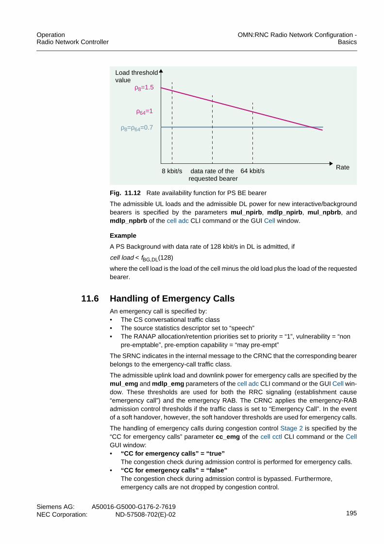
OperationRadio Network Controller
OMN:RNC Radio Network Configuration -Basics
Siemens AG: A50016-G5000-G176-2-7619NEC Corporation: ND-57508-702(E)-02 195
Fig. 11.12 Rate availability function for PS BE bearer
The admissible UL loads and the admissible DL power for new interactive/backgroundbearers is specified by the parameters mul_npirb , mdlp_npirb , mul_npbrb , andmdlp_npbrb of the cell adc CLI command or the GUI Cell window.
Example
A PS Background with data rate of 128 kbit/s in DL is admitted, if
cell load < fBG,DL(128)
where the cell load is the load of the cell minus the old load plus the load of the requestedbearer.
11.6 Handling of Emergency CallsAn emergency call is specified by:• The CS conversational traffic class• The source statistics descriptor set to “speech”• The RANAP allocation/retention priorities set to priority = “1”, vulnerability = “non
pre-emptable”, pre-emption capability = “may pre-empt”
The SRNC indicates in the internal message to the CRNC that the corresponding bearerbelongs to the emergency-call traffic class.
The admissible uplink load and downlink power for emergency calls are specified by themul_emg and mdlp_emg parameters of the cell adc CLI command or the GUI Cell win-dow. These thresholds are used for both the RRC signaling (establishment cause“emergency call”) and the emergency RAB. The CRNC applies the emergency-RABadmission control thresholds if the traffic class is set to “Emergency Call”. In the eventof a soft handover, however, the soft handover thresholds are used for emergency calls.
The handling of emergency calls during congestion control Stage 2 is specified by the“CC for emergency calls” parameter cc_emg of the cell cctl CLI command or the CellGUI window:• “CC for emergency calls” = “true”
The congestion check during admission control is performed for emergency calls.• “CC for emergency calls” = “false”
The congestion check during admission control is bypassed. Furthermore,emergency calls are not dropped by congestion control.
Load thresholdvalue
Rate8 kbit/s 64 kbit/sdata rate of the
requested bearer
ρ8=ρ64=0.7
ρ8=1.5
ρ64=1

OMN:RNC Radio Network Configuration -Basics
OperationRadio Network Controller
196Siemens AG:A50016-G5000-G176-2-7619NEC Corporation:ND-57508-702(E)-02
During congestion control stage 1, however, the “CC for emergency calls” flag is notchecked.
If RAB pre-emption is active, the emergency call uses the emergency call threshold in-stead of the highest threshold of any traffic class. If admission control rejects the setup,normal pre-emption handling is applied. For more information see Pre-Emption.
If Pre-Emption is active, emergency calls can be identified on the Iur interface based onthe allocation/retention priority. The DRNC sends the traffic class information to theCRNC in the RNSAP RL SETUP REQUEST message, the RL ADDITION REQUESTmessage, and the RNSAP RL RECONFIGURATION PREPARE message.
An emergency call is identified by the “TrCh Source Statistics” descriptor set to “speech”and the allocation/retention priorities set to priority = “1”, vulnerability = “non pre-empt-able”, pre-emption capability = “may pre-empt”. The traffic class is set toJE_CRNC_TRAFFIC_CLASS_EMERGENCY_CALL for emergency calls and toJE_CRNC_TRAFFIC_CLASS_IUR for all other calls. In the event of an emergency call,the admission control threshold for emergency calls is used. Otherwise, the admissioncontrol threshold for the Iur interface is used.
11.7 Admission Control for HSDPAThe HSDPA feature requires functionality to admit UEs onto the physical HSDPAchannel, that is the HS-PDSCH. UEs which support HSDPA are only admitted to theHS-PDSCH if certain preconditions, such as a successful load check and the support ofthe applied service or bearer on the HS-DSCH, are fulfilled.
The A-DPCH and the uplink HS-DPCCH are the only channels subject to admissioncontrol, given that the HS-PDSCH and the HS-SCCH use the power left from DCH usersand when an HS-DSCH needs to be established.
For more information see FD012249 - Support of HSDPA.
11.8 Restriction ControlManual restriction is applied by the OMC/LMT-RNC operator by changing the office dataor by issuing a command to the RNC. The restrictions prevent UEs from placing a callor even prevent them from being camped on a cell. Some types of restriction rely on anaccess class which basically is a number which is assigned to each UE. All types ofmanual restrictions can be imposed on a single cell or on a range of cells.
Access classes
All UEs are assigned an access class in the range 0..15.
The access classes from 15 to 11 are reserved for:• PLMN staff (class 15)• Emergency services (class 14)• Public utilities such as gas/water suppliers (class 13)• Security services (class 12)• PLMN operators (class 11)
i NOTEEmergency calls can be identified on the Iur interface only if the Pre-Emption feature isactive.

OperationRadio Network Controller
OMN:RNC Radio Network Configuration -Basics
Siemens AG: A50016-G5000-G176-2-7619NEC Corporation: ND-57508-702(E)-02 197
All classes from 0 to 9 denote “normal” UEs, with no further discrimination or rankingbetween them. Access classes 0..9 are allocated randomly.
Access class 10 denotes a “normal” UE which attempts to place an emergency call, i.e.,a UE temporarily takes on access class 10 instead of its assigned class when anemergency number is entered. For UEs with access classes 11 to 15, emergency callsare allowed unless both, access class 10 and the relevant access class (11 to 15), arebarred.
Manual restriction types
The following restriction types are available:• Cell barring
prevents any UE from accessing the cell. Existing calls are not affected.For example, cell barring can be used to empty a cell of all UEs prior to a plannedshut-down of the cell.
• Cell reserved for operator useprevents UEs with access classes 0..9 from accessing the cell. Existing calls are notaffected.
• Access class barringThe mod rstm CLI command defines access class restriction control levels in steps0 to 10. 10 restriction control patterns are applied to each control level. Thisrestriction control pattern consist of combinations of restricted and unrestrictedcontrolling for each access class.The restriction control level 0 means no restriction control, level 1 means 10%restriction control, and level 10 means 100% restriction control. It is possible tochange the restriction control pattern at will if necessary. It is allowed to change therestriction control pattern for each level separately.
• PS bearer maximum rate restrictionThis type is used to restrict the maximum data transmission rate available in a cellper user. The RNC does not establish or reconfigure a radio link if the requested rateis above the maximum rate specified for the cell. The maximum rate is only appliedfor the DL rate.
The supported PS services are:– 64K UL / 64K DL– 64K UL / 128K DL– 64K UL / 384K DLThe maximum rate available in a cell is specified by the cell iub CLI command or theGUI Cell window.

OMN:RNC Radio Network Configuration -Basics
OperationRadio Network Controller
198Siemens AG:A50016-G5000-G176-2-7619NEC Corporation:ND-57508-702(E)-02
Cells reserved for operator use
The operator may reserve a range of IMSIs for operator UEs only. The start and end ofthe range is configured by the rnc CLI command or the GUI RNC window.
Once the RNC has received the notification that the cell is reserved, the RNC will treatthis cell like any other cell with regard to operator UEs. However, the RNC does notallow non-operator UEs to hand over to the cell. Non-operator UEs do not camp on thecell or select it for RRC connection establishment/cell update/URA update.
If handover to the restricted cell is triggered for the UE, the RNC performs inter-frequen-cy handover instead. The handover fails and the call may eventually be lost if the UEcannot be handed over to another frequency, e.g. all available cells are currentlyreserved for operator use as well. In this case, the RNC forces the UE to attemptreestablishment on another cell by deleting all radio links for the UE. The reservation issignaled on system information.
Example
cre rstm kind=perset peri=12
cre rstm kind=acccls accrstl=0 cellid=all
cre rstm kind=accptn accrstl=1 ptn1=1000000000000000ptn2=0100000000000000 ptn3=0010000000000000ptn4=0001000000000000 ptn5=0000100000000000ptn6=0000010000000000 ptn7=0000001000000000ptn8=0000000100000000 ptn9=0000000010000000ptn10=0000000001000000
cre rstm kind=accptn accrstl=2 ptn1=1000010000000000ptn2=0100001000000000 ptn3=0010000100000000ptn4=0001000010000000 ptn5=0000100001000000ptn6=1000010000000000 ptn7=0100001000000000ptn8=0010000100000000 ptn9=0001000010000000ptn10=0000100001000000
...
cre rstm kind=accptn accrstl=10 ptn1=1111111111000000ptn2=1111111111000000 ptn3=1111111111000000ptn4=1111111111000000 ptn5=1111111111000000ptn6=1111111111000000 ptn7=1111111111000000ptn8=1111111111000000 ptn9=1111111111000000ptn10=1111111111000000
The mod rstm CLI command specifies the manual restriction control parameters.kind=perset peri=12 specifies the restriction control period. kind=acccls accrstl=0specifies the access class restriction level 0 that means “no restriction control”.kind=accrstl=1-10 specifies the restriction control pattern ptn1 - ptn10 for eachrestriction level.

OperationRadio Network Controller
OMN:RNC Radio Network Configuration -Basics
Siemens AG: A50016-G5000-G176-2-7619NEC Corporation: ND-57508-702(E)-02 199
11.8.1 Restriction Control MechanismRestriction control is allocated in the admission control and is performed on a single PSBE call or a multi-call including a PS BE whenever a new bearer is set up, added, orreconfigured. Restriction control checks whether the spreading factor of the requestedbearer is allowed. The spreading factor is allowed if the minimum available spreadingfactor min_sf is lower or equal to the DL spreading factor of the requested bearer. Theparameter min_sf is specified by the cell adc CLI command or the GUI Cell window. Ifthe spreading factor is not allowed, the call/reconfiguration is rejected. The restrictioncontrol check is performed prior to the load check.
Tab. 11.1 shows the minimum DL spreading factor values and the correspondingmaximum allowable rates for single PS BE bearer. The maximum allowable PS BE ratesis lower for bearer combinations of a PS BE with another higher-rate RAB, the maximumallowable PS BE.
Restriction control is only performed in DL for single- and multi-call RABs that canperform Bit Rate Adaptation. A scenario where the UE is configured to its minimum rateor the only possible rate is treated as failure due to bit rate adaptation. As result, thereestablishment procedure is triggered. Since this information is only available in theSRNC, the SRNC sends a flag to the CRNC which indicates whether restriction controlis applied or not. If the traffic class is not known, restriction control will be applied, inother words restriction control is applied to all traffic classes on the Iur interface.
Minimum DL spreadingfactor values
Maximum allowed rates
8 PS BE 384 kbit/s
16 PS BE 128 kbit/s
32 PS BE 64 kbit/s
Tab. 11.1 Minimum DL spreading factor for single PS BE bearer

OMN:RNC Radio Network Configuration -Basics
OperationRadio Network Controller
200Siemens AG:A50016-G5000-G176-2-7619NEC Corporation:ND-57508-702(E)-02
The handling of a soft handover to a cell with restricted spreading factor for PS I/B andPS I/B + CS AMR/UDI combinations is based on the setting of the“HO_PSRateRestrictionHandler” parameter ho_psrrh of the rnc CLI command or theGUI RNC window:• Restrict_Then_Handover (rtho)
The SRNC reconfigures the existing PS bearer to the minimum rate and proceedswith the soft handover procedure for the radio link(s).If the bit rate adaptation procedure fails due to any reason, the SRNC triggers theRRC reestablishment procedure. If the soft handover procedure fails due to anyreasons, the RRC reestablishment procedure is performed.
• Handover_Then_Restrict (hotr)The SRNC performs the soft handover branch addition by calling the current softhandover procedure. The admission control then temporarily ignores the minimumspreading factor restriction. Afterward, the SRNC reconfigures the existing PSbearer to the minimum rate.On the Iur interface, this handling is not possible. Therefore, the rate is restrictedbefore the handover for both parameter values rtho and hotr .If the soft handover branch addition procedure fails due to any reasons, the RRCreestablishment procedure is performed. If the bit rate adaptation procedure failsdue to any reasons, the SRNC triggers the RRC reestablishment procedure.
• No_Handling (nh)The normal soft handover failure handling is applied. After a soft handover failuretriggered by event 1A or 1C, the PS rate is reconfigured to the minimum rate by bitrate adaptation and a retry is performed. If the retry fails, the connection reestablish-ment procedure is initiated.After a soft handover failure triggered by event 1A’, the connection reestablishmentprocedure is initiated.
Example
cre rnc rncid=1519 mcc=262 mnc=02 a2ea_idi=0a2ea_dsp=0000000000000000000000 opc=00983 udpp_rnc=2152udpp_sgsn=2152 nwind_ps=2 dpc_ps=50332 nwind_cs=2 dpc_cs=50172drxclc_ps=6 drxclc_cs=6 sc_rnc=1 cnodei=falseopue_ibase=0000000000 opue_iofs=0 ho_psrrh=hotr tmr_iubhc=60ipadr_cbc=10.8.16.26 type_ldc=none ecm_2abm=true fband_gsm=noneflag_upgrd=new mmco=iffst ifho_wocm=true srdch_upgrd=false
The parameter ho_psrrh parameter of the rnc CLI command specifies the handling ofa soft handover to a cell with restricted spreading factor for PS I/B and PS I/B + CSAMR/UDI combinations.

OperationRadio Network Controller
OMN:RNC Radio Network Configuration -Basics
Siemens AG: A50016-G5000-G176-2-7619NEC Corporation: ND-57508-702(E)-02 201
11.8.2 Restriction Control in the CRNC for HSDPA
Within an HSDPA enabled network, it is expected that PS radio bearers will beestablished on HS-PDSCH instead of making use of the DCH.
However, the following situations lead to the preferred choice to set up a PS bearer onthe DCH:• HSDPA is not supported by the UE• The requested multicall/bearer combination is not supported by HSDPA standards• The Node B is out of resources on the CH-Card, but a retry on DCH state might be
possible
Restriction control in the CRNC thus offers the following benefits to operators:• The network operator can limit the risk that R99-capable-only-UEs or HSDPA-
capable UEs (if resource allocation on the HS-DSCH is not allowed), consume thecell capacity and thus degrade HSDPA performance due to the lack of availableresources.Note: HSDPA can only make use of the remaining power after DPCH bearers havebeen served.
• Operators will also benefit that the performance for DCH users is not affected duringlow HSDPA traffic periods.
For more information about this feature, refer to the feature description FD012255 -Restriction Control for PS Bearers.
i NOTEHSDPA restriction control is an optional feature and, therefore, only enabled if thefeature is part of the contract.

OMN:RNC Radio Network Configuration -Basics
OperationRadio Network Controller
202Siemens AG:A50016-G5000-G176-2-7619NEC Corporation:ND-57508-702(E)-02
11.9 Admission Control in the Node BAn admission control algorithm is implemented in the Node B to protect the Node Bagainst too much power after radio link setup, addition, or reconfiguration.
The admission control in the RNC has a long-term view and admits a new radio link ifthe QoS for the new radio link and the already existing radio links can be guaranteed.The admission control in the Node B has a snap-shot view and verifies whether thepower requirement of the new bearer is below the available power capacity at themoment of the setup or the reconfiguration.
The admission control in the RNC is triggered by RNSAP RL SETUP/ADDITIONREQUEST and RNSAP RL RECONFIGURATION PREPARE messages. Theadmission control in the Node B is triggered by NBAP RL SETUP/ADDITION REQUESTand NBAP RL RECONFIGURATION PREPARE messages. Therefore, the admissioncontrol in the RNC is called first. If the radio link is admitted by the RNC, the admissioncontrol in the Node B is called.
The maximum allowable downlink transmission power max_dltp is specified per cellinstance by the cell iub CLI command or the GUI Cell window.
Admission control upon radio link setup
The Node B stores the estimated transmission power (P_Est) and the maximum DLpower (Pmax) of its existing RL configurations locally. The transmission power and themaximum downlink power are maintained by the Node B per radio link of the sameNode B communication context.
The Node B performs the following admission control handling individually to each of theradio links to be set up since the radio link setup message may involve more than 1 radiolink(s):
a) The initial power P_Est is specified by the RL SETUP REQUEST message.b) The maximum DL power Pmax is specified by the RL SETUP REQUEST message.
Pmax is needed if subsequent RL RECONFIGURATION PREPARE messages ofthis radio link do not include the maximum DL power.
c) A radio link setup is admitted if the following condition is true:Transmitted carrier power + P_Est <= Max transmission power * Offset 1where all values are linear values. Offset 1 is derived from system data and has noimpact on admission control.If a radio link setup is not admitted, the Node B sends a RADIO LINK SETUPFAILURE message with the cause value “Power Level Not Supported”.
Radio link addition
The Node B stores the estimated transmission power (P_Est) and the maximum DLpower (Pmax) of its existing RL configurations locally. The transmission power and themaximum downlink power are maintained by the Node B on a per radio link basis of thesame Node B communication context.
i NOTEIf the operator changes the offsets used in the Node B, the power thresholds for theadmission control in the RNC must be reconfigured in such a way that they are belowor equal to the power thresholds for the admission control in the Node B.

OperationRadio Network Controller
OMN:RNC Radio Network Configuration -Basics
Siemens AG: A50016-G5000-G176-2-7619NEC Corporation: ND-57508-702(E)-02 203
The Node B performs the following admission control handling individually to each of theradio links to be added since the radio link addition message may involve more than 1radio link(s):
a) The initial power P_Est is specified by the RL ADDITION REQUEST message.If P_Est is not included in the NBAP RL ADDITION REQUEST message:P_Est = MAX [P_Est of existing RLs]
b) The maximum DL power Pmax is specified by the RL ADDITION REQUESTmessage.If Pmax is not included in the NBAP: RL ADDITION REQUEST message:Pmax = MAX [ Pmax of existing RLs ]Pmax is needed if subsequent RL RECONFIGURATION PREPARE messages ofthis radio link do not include the maximum DL power.
c) A radio link addition is admitted if the following condition is true:Transmitted carrier power + P_Est <= Max transmission power * Offset 2where all values are linear values. Offset 2 is derived from system data and has noimpact on admission control.If a radio link addition is not admitted, the Node B sends a RADIO LINK ADDITIONFAILURE message with the cause value “Power Level Not Supported”.
Radio link reconfiguration
The Node B locally overwrites the estimated transmission power (P_Est) and itsmaximum DL power (Pmax) of its existing radio link configurations. The transmissionpower and the maximum downlink power are maintained by the Node B on a per radiolink basis of the same Node B communication context.
The Node B performs the following admission control handling individually to each of theradio links to be reconfigured since the radio link setup message may involve more than1 radio link(s):
a) The maximum DL power Pmax is specified by the NBAP: RL RECONFIGURATIONPREPARE message.The new Pmax value for this particular radio link is applied by the Node B in part (b)and (c). The Node B, however, does not overwrite its locally stored Pmax value withthis new Pmax since the RL RECONFIGURATION COMMIT message has not beenaccomplished.If the maximum DL power is not included in the NBAP: RL RECONFIGURATIONPREPARE message, the current locally stored Pmax value is used. That is the Pmaxstored at radio link setup, radio link addition, or previous radio link reconfiguration.
b) A radio link reconfiguration is admitted if the following condition is true:Transmitted carrier power + min[P_Est * (SFbefore/SFafter), Pmax ] - P_Est<= Max transmission power * Offset 3where all values are linear values.P_Est is the current value of the estimated transmission power for the Node B’sexisting radio link configurations right before the new radio link reconfiguration takesplace. Pmax is derived from (a). SFbefore and SFafter specify the spreading factorright before and right after the radio link reconfiguration. Offset 3 is derived fromsystem data and has no impact on admission control.If a radio link reconfiguration is not admitted, the Node B sends a RADIO LINKRECONFIGURATION FAILURE message with the cause value “Power Level NotSupported”.

OMN:RNC Radio Network Configuration -Basics
OperationRadio Network Controller
204Siemens AG:A50016-G5000-G176-2-7619NEC Corporation:ND-57508-702(E)-02
c) The Node B overwrites its estimated transmission power (P_Est) upon the receptionof the RL RECONFIGURATION COMMIT message:P_Est = MIN [ P_Est' * (SFbefore/SFafter), Pmax ]where P_Est' is the last estimated transmission power of the Node B before thecurrent radio link reconfiguration procedure is invoked. P_Est is the latest estimationtransmission power upon the completion of RL reconfiguration procedure. Pmax isderived from (a).The Node B overwrites its locally stored Pmax value with the new Pmax specified bythe NBAP: RL RECONFIGURATION PREPARE message upon the reception of theRL RECONFIGURATION COMMIT message if there is a new Pmax value, see part(a).
11.9.1 Admission Control in the Node BNo HSDPA-specific admission control mechanism exists in the Node B with regard topower resources. This is caused by the fact that power resource handling is a matter ofHSDPA admission control in the CRNC. The Node B, however, may reject bearers dueto a lack of resources, for example on the HSDPA-capable channel card.
In other words, the HSDPA-capable CHC has full HSDPA capacity on the downlink.Therefore, CHC resource shortage cannot happen on the downlink. On the uplink, how-ever, CHC resource shortage may occur due to the associated DPCH.
The setup of the associated DL DPCH is treated by the Node B’s admission controlalgorithm for dedicated channels (DCH) state. This admission control algorithm isextended in such a way that, in HSDPA cells, its operation is based on the non-HSDPApower rather than on the transmitted carrier power.
11.10 Pre-EmptionThe operator can control UTRAN resource allocation to users and/or services byallocating priorities and pre-emption properties to different RABs. When resources arescarce, the RNC can use these parameters for an optimal resource allocation. For moreinformation on pre-emption see FD:Pre-Emption.
If the core network requests the establishment of a RAB upon RAB establishment,SRNC relocation, or inter-RAT handover to UTRAN, it provides the allocation/retentionpriority attributes of this RAB:• Priority level
There are 14 priority levels available from highest priority (1) to lowest priority (14).Furthermore, the value (15) is available that indicates “no priority”.
• Pre-emption capabilityThe pre-emption capability indicates whether the RAB may or may not triggerpre-emption.
• Pre-emption vulnerabilityThe pre-emption vulnerability indicates whether the RAB is or is not pre-emptable.
The SRNC maps the RAB allocation/retention priority attributes received from the corenetwork onto dedicated channel (DCH) allocation/retention priorities.

OperationRadio Network Controller
OMN:RNC Radio Network Configuration -Basics
Siemens AG: A50016-G5000-G176-2-7619NEC Corporation: ND-57508-702(E)-02 205
These priorities are then mapped onto radio link allocation/retention priorities which areused by the CRNC to perform radio link pre-emption:• Radio link allocation priorities
Identify which radio links can pre-empt others• Radio link retention priorities
Identify radio links that can be pre-empted
The RNC-based radio link pre-emption frees codes and/or reduces the cell load in orderto allocate resources to high priority users.
If pre-emption is required, the CRNC selects radio links for pre-emption and informs theSRNC. The SRNC deletes these radio links based on the type of RAB:• Triggering RRC connection re-establishment to common channels• Releasing the RRC connection if the connection cannot be switched to CELL_FACH
The freed resources are assigned to high priority users after the deletion of the radiolinks is completed.
For more information on the use of retention priorities in the event of a congestion seeCongestion Control and Pre-Emption.
11.10.1 RNC-Based Radio Link Pre-EmptionThe core network may include the allocation/retention priority for each RAB to be set upby the UTRAN in the RANAP RAB ASSIGNMENT REQUEST or RELOCATIONREQUEST messages, see Tab. 11.2.
If the allocation/retention priority is not specified in the RAB ASSIGNMENT REQUESTmessage, the allocation request cannot trigger pre-emption. The connection is pre-emptable and has the value “lowest” as priority level.
The SRNC stores the allocation/retention priority for the duration of the call if the Pre-Emption feature is activated. If the Pre-Emption feature is deactivated, the allocation
i NOTELoad-Based Bit Rate Adaptation and pre-emption have similar functionalities.Therefore, these mechanisms can not be active at the same time. The pre-ferred feature is enabled by NEC/SAG staff.
Allocation/retention priority
Priority level spare (0),highest (1), ..,lowest (14),no priority (15)
Pre-emption capability shall not trigger pre-emption,may trigger pre-emption
Pre-emption vulnerability not pre-emptable,pre-emptable
Tab. 11.2 Allocation/retention priority

OMN:RNC Radio Network Configuration -Basics
OperationRadio Network Controller
206Siemens AG:A50016-G5000-G176-2-7619NEC Corporation:ND-57508-702(E)-02
request cannot trigger the pre-emption process. The connection is not pre-emptable andis considered to have the value “no priority” as priority level.
For the SRNC emergency call handling of all UE connections to the CN domain that donot include an Iur connection, regardless of the activation of the Pre-Emption feature,see FD012240 - Admission Control of Prioritized Bearers.
11.10.1.1 SRNC Setting of the DCH Allocation/Retention PriorityThe SRNC maps the RAB allocation/retention priorities received from the core networkonto DCH allocation/retention priorities. If a RAB is carried by one or more DCHs, theallocation/retention priority for the DCH(s) is the same as the RAB allocation/retentionpriority. This feature does not support the handling of more than one RABs multiplexedonto a single DCH.
Whenever a radio link needs to be set up or reconfigured, the SRNC provides the DCHallocation/retention priorities to the DRNC via RNSAP signaling. The RNSAPallocation/retention priority for a DCH is derived from the RANAP allocation/retentionpriority for a RAB. In case of radio link addition, the DRNC uses the allocation/retentionpriority information from any of the already existing radio links. Furthermore, the SRNCmaps the DCH allocation/retention priority onto the radio link allocation/retention priority.The SRNC provides this information to the CRNC via internal signaling prior to the loadcheck and the code allocation performed by the admission control of the CRNC.
The SRNC sets the allocation/retention priority of the DCH carrying the dedicatedcontrol channel (DCCH) signaling in a way that pre-emption cannot be triggered and theconnection has the value “lowest” as priority level. The connection is pre-emptable if theDCCH is combined with at least one RAB. The signaling of RRC connections, however,is not pre-emptable. Thus, the allocation/retention priority of the signaling DCH takesprecedence over the priority of the DCHs carrying RABs.
If the Pre-Emption feature is deactivated, the SRNC sets the allocation/pre-emptionpriority of the DCH carrying the DCCH signaling in a way that pre-emption cannot betriggered. The connection is not pre-emptable and is considered to have the value“no priority” as priority level.
The SRNC sets the DCH pre-emption capability of all DCHs in a RAB combinationbased on the rate of the PS BE DCH:• The rate of the PS BE DCH is higher than the minimum rate
Pre-emption is not triggered.
Therefore, PS BE RABs that may trigger pre-emption cannot pre-empt other usersto obtain:– A higher rate at rate increase during bit rate adaptation– A DCH at channel-type-switching from Cell_FACH to Cell_DCH
During bit rate adaptation at a minimum rate, pre-emption may occur in the event of:– Rate increases during bit rate adaptation from 0/0 kbit/s to the initial rate if the ini-
tial rate is identical to the minimum rate.– An admission control failure occurs while moving from 0/0 kbit/s to the initial rate
and a retry is performed at the minimum rate.
i NOTEThe emergency call handling in the DRNC is not supported if the pre-emptionfunctionality in the SRNC is deactivated.

OperationRadio Network Controller
OMN:RNC Radio Network Configuration -Basics
Siemens AG: A50016-G5000-G176-2-7619NEC Corporation: ND-57508-702(E)-02 207
• The rate of the PS BE DCH is equal to the minimum rate or 0/0 kbit/sThe DCHs pre-emption capability is derived from the stored RABallocation/retention priority.
Whenever there is a change on the RAB combination or in the radio bearers data rate,the SRNC checks the above condition. If the DCH pre-emption capability is differentfrom the value already sent to the CRNC/DRNC, the SRNC will inform them. The CRNCis informed by internal signaling whereas the DRNC is informed by the RNSAP radio linkreconfiguration procedure.
A retry is performed with the minimum rate of the PS BE RAB at RABestablishment/reestablishment/modification and soft-handover failure. In case of afailure, pre-emption may be triggered.
11.10.1.2 DRNC Handling of the DCH Allocation/Retention PriorityThe DRNC performs the mapping onto the radio link allocation/retention priority uponreception of an RNSAP RADIO LINK SETUP REQUEST or a RADIO LINKRECONFIGURATION PREPARE message containing the allocation/retention priority.The DRNC forwards the information to the CRNC before the CRNC performs the loadcheck and code allocation.
The DRNC stores the DCH and radio link allocation/retention information for theduration of the call. Upon reception of an RNSAP RADIO LINK ADDITION REQUESTmessage, the DRNC forwards the stored radio link allocation/retention priority from anyof the already existing radio links to the CRNC.
If the pre-emption feature is switched off, the DRNC sets the DCH allocation/retentionpriority in a way that pre-emption cannot be triggered, the connection is not pre-empt-able and has the value “no priority” as priority level.
11.10.1.3 SRNC/DRNC Mapping of the DCH to the Radio LinkAllocation/Retention PriorityEvery time a radio link is set up or reconfigured, the SRNC/DRNC derives from theDCH’s allocation/retention priorities:• The allocation information of a radio link (according to 25.423 Annex A.1)
The allocation information of the radio link is used to determine whether or not theradio link can pre-empt other radio links.
A radio link can trigger pre-emption if– the radio link pre-emption capability is “may trigger pre-emption” AND– the radio link allocation priority is between 1 and 13.
• The retention information of a radio link (according to 25.423 Annex A.2)The retention information of the radio link is used to determine whether or not theradio link can be pre-empted by other radio links.
A radio link is pre-emptable if– the radio link pre-emption vulnerability is “pre-emptable” AND– the radio link retention priority is between 2 and 14.
The radio link pre-emption vulnerability is set to “not pre-emptable” if the priority level ofone or more of the DCHs is set to “no priority”.

OMN:RNC Radio Network Configuration -Basics
OperationRadio Network Controller
208Siemens AG:A50016-G5000-G176-2-7619NEC Corporation:ND-57508-702(E)-02
11.10.1.4 CRNC Radio Link Pre-EmptionFor each cell, the CRNC maintains a list of all radio links that can be pre-empted.This list is sorted by:• The priority in ascending order• The downlink spreading factor in an ascending order within the radio links of the
same retention priority
The list of pre-emptable radio links is updated upon completion of any procedure thatalters the radio links established in the cell. Furthermore, the list is updated with thelatest radio link allocation/retention priorities received from the SRNC/DRNC prior toperforming admission control.
The CRNC may trigger radio link pre-emption if the load check and/or the codeallocation during admission control fails.
Load check and code allocation
The downlink load check is performed prior to the uplink load check. The CRNC checksthe radio link pre-emption capability before performing the load check:• The radio link “shall not trigger pre-emption”
The CRNC checks if there is any ongoing pre-emption procedure in the cell:– If there is no ongoing pre-emption procedure in the cell, the CRNC proceeds with
the existing load check (DL followed by UL).– If there is at least one pre-emption procedure in the cell, the CRNC fails the load
check without performing the load check procedure. Exceptions of this handlingare: A soft handover branch addition, bit rate adaptation to reduce the rate, radiobearer release, establishment of an emergency RAB, an emergency call relatedRRC connection establishment, and an NAS related RRC connection establish-ment. In this cases, the existing load check procedure is performed.
• The radio link “may trigger pre-emption”
The CRNC performs the load check using the highest admission threshold:– The maximum threshold [conversational, streaming, interactive, background]– The soft/softer handover threshold in the event of a soft/softer handover– The emergency call threshold in the event of an emergency call
Afterward, the CRNC performs the code allocation even if the load check fails in ULor DL. There are four cases:– If the load check is successful and the code allocation is successful, the bearer is
admitted.– If the load check is successful and the code allocation fails, the CRNC initiates the
pre-emption process of lower priority radio links, see Pre-emption process due tocode allocation failure.
– If the load check fails and the code allocation is successful, the CRNC initiates thepre-emption process of lower priority radio links, see Pre-Emption due to loadcheck failure.
– If the load check fails and the code allocation fails, the CRNC initiates the pre-emption process of lower priority radio links, see Pre-emption process due to loadcheck and code allocation failure.

OperationRadio Network Controller
OMN:RNC Radio Network Configuration -Basics
Siemens AG: A50016-G5000-G176-2-7619NEC Corporation: ND-57508-702(E)-02 209
Pre-Emption due to load check failure
Once the pre-emption procedure has been triggered due to load check failure, theCRNC checks the ordered list of pre-emptable radio links and selects the radio links tobe pre-empted.
The radio links to be pre-empted are selected as follows:• Radio links are selected in ascending order of priority with the lowest priority first.• Only those radio links can be selected that have a lower priority than the RAB to be
established.• Radio links belonging to the UE that triggered pre-emption are excluded from the
selection process.
The CRNC estimates the load decrease due to the radio links to be pre-empted and theload increase due to the new radio link. The CRNC selects as many radio links asnecessary in order to maintain the cell load level, in other words the cell load after thepre-emption process should be the same as before. If it is not possible to match theexact value the final load should never be greater than the initial load.
The following equation is valid:
where:
∆ρi, release is the load change due to release of radio link i.
∆ρi, establish is the load change due to establishment/modification of the new radio link.
∆ρ can be calculated in terms of theoretical load. n is the number of radio links to be pre-empted.
The CRNC stores the load information for the duration of the call in order to perform theabove calculation. If the radio links to be pre-empted are selected, the CRNCimmediately removes them from the list of pre-emptable radio links in that cell. Thus, itis avoided that parallel pre-emption procedures select the same radio links. The CRNCthen informs the SRNC/DRNC of the radio links that need to be pre-empted and startsthe Tpreempt timer.
Pre-emption process due to code allocation failure
Once the pre-emption procedure has been triggered due to code allocation failure, theCRNC checks the list of pre-emptable radio links. The pre-emptable radio links are listedin ascending order of priority with the lowest priority first.
The radio links to be pre-empted are selected as follows:• The CRNC selects the first radio link with a DL spreading factor equal to or lower
than the spreading factor of the radio link that is to be setup or modified.• Only those radio links can be selected that have a lower priority than the RAB to be
established.• Radio links belonging to the UE that triggered pre-emption are excluded from the
selection process.
If the radio links to be pre-empted are selected, the CRNC immediately removes themfrom the list of pre-emptable radio links in that cell. Thus, it is avoided that parallel pre-emption procedures select the same radio links. The CRNC then informs theSRNC/DRNC of the radio links that need to be pre-empted and starts the Tpreempt timer.
∆ρi release,i 1=
n
∑ ∆ρestablish≥

OMN:RNC Radio Network Configuration -Basics
OperationRadio Network Controller
210Siemens AG:A50016-G5000-G176-2-7619NEC Corporation:ND-57508-702(E)-02
Pre-emption process due to load check and code allocation failure
Once the pre-emption procedure has been triggered due to load check and codeallocation failure, the selects the radio links to be pre-empted according to Pre-emptionprocess due to code allocation failure.
After the selection process, the RNC checks if the following equation is valid:
where:
∆ρi, release is the load change due to release of radio link i.
∆ρi, establish is the load change due to establishment/modification of the new radio link.
∆ρ can be calculated in terms of theoretical load. n is the number of radio links to be pre-empted.
If the equation is valid, the CRNC proceeds with pre-empting the selected radio links.
If the above equation is not satisfied, the CRNC selects additional pre-emptable radiolinks until the equation is valid. The CRNC then proceeds with the pre-emption of allselected radio links and starts the Tpreempt timer.
11.10.1.5 Release of ResourcesThe RNC is informed that a radio link needs to be pre-empted by internal CRNCindication or reception of an RNSAP RADIO LINK PREEMPTION REQUIREDINDICATION message. The RNC may act as an SRNC or a DRNC for every radio link.
RNC as DRNC
If the RNC acts as DRNC, it starts the release of resources upon reception of:• An internal CRNC indication to pre-empt a radio link.
The DRNC prepares the RNSAP RADIO LINK PREEMPTION REQUIREDINDICATION message and forwards it to the SRNC. Furthermore, the DRNC sends onemessage per CRNC communication context ID to indicate pre-emption of all radio linksof that context. The DRNC always requests pre-emption of all radio links in order toincrease the possibilities that other vendor SRNCs release the entire UE connectionrather than deleting individual radio links.
∆ρi release,i 1=
n
∑ ∆ρestablish≥

OperationRadio Network Controller
OMN:RNC Radio Network Configuration -Basics
Siemens AG: A50016-G5000-G176-2-7619NEC Corporation: ND-57508-702(E)-02 211
RNC as SRNC
If the RNC acts as SRNC, it starts the release of resources upon reception of:• An internal CRNC indication to pre-empt a radio link• An RNSAP RADIO LINK PREEMPTION REQUIRED INDICATION message
The SRNC checks the RAB combination carried by the radio link to be pre-empted:• Single PS BE RABs:
On the Iub interface, the RNC checks whether there is an on-going procedure uponreception of the trigger to release the resources:– If there is an on-going procedure other than re-establishment in CELL_FACH -
ACTIVE state, the RNC initiates the RRC connection release procedure andsends an RANAP IU RELEASE REQUEST message to the PS CN domain withthe cause value set to “RAB pre-empted”. If there is also the CS domain present,the cause for the CS domain is set to “Release due to UTRAN Generated Rea-son”.
– If there is an on-going re-establishment in CELL_FACH - ACTIVE state, the RNCignores the trigger and proceeds with completion of the re-establishmentprocedure.
– Otherwise, the RNC releases all dedicated resources apart from Iu resources andPRLC(s) and initiate the resource re-establishment procedure in CELL_FACH -ACTIVE state.
On the Iur interface, the RNC releases all dedicated resources apart from Iuresources and PRLC(s) upon reception of the pre-emption trigger.Upon reception of the RRC CELL UPDATE message via RNSAP UPLINKSIGNALLING TRANSFER INDICATION, the RNC initiates the RRC connectionrelease procedure and sends an RANAP IU RELEASE REQUEST message to thePS CN domain with the cause value set to “RAB pre-empted”. If there is also a CSsignalling connection present, the RNC also sends an RANAP IU RELEASEREQUEST message to the CN domain with the cause set to “Release due toUTRAN Generated Reason”.
• Other RAB combinations:The SRNC initiates the RRC connection release with the cause “preemptiverelease”.
The RNC sends an RANAP IU RELEASE REQUEST message to the affected CNdomain with the following cause values:– “RAB pre-empted” to the CN domain for which an RAB exists– “Release due to UTRAN Generated Reason” to the CN domain that only has a
signaling connection
Pre-emption is handled in the same way as a user plane failure. The RAB is releasedregardless of the response of the core network. Furthermore, the RRC connection isreleased if the active set contains more than one radio link. If the release of an RRCconnection is triggered, it takes place even if the active set contains more than one radiolink. Otherwise, a load increase could occur if the pre-empted radio link is admitted againdue to a high soft handover threshold.

OMN:RNC Radio Network Configuration -Basics
OperationRadio Network Controller
212Siemens AG:A50016-G5000-G176-2-7619NEC Corporation:ND-57508-702(E)-02
11.10.1.6 Establishment of ResourcesOnce the pre-empted resources in the cell are deleted, the CRNC stops the Tpreempttimer. The admission control function in the CRNC performs load and code allocation forthe radio links that triggered the pre-emption procedure based on the reasons for theprevious admission control failure. Upon successful code allocation, the CRNC informsthe SRNC/DRNC of successful admission control.
The load check is skipped because in most cases the current load is above theadmission threshold. If the pre-emption procedure is completed, the load level shouldnot be higher than the load at the beginning of the procedure.
11.10.1.7 Parallel Pre-Emption ProceduresParallel pre-emption procedures are allowed but the CRNC does not allow simultaneousselection of pre-emptable radio links from the ordered list. That is, only one pre-emptionprocedure can select pre-emptable radio links at any given time and these radio linksare removed from the list when the selection is complete. If selected radio links are notpre-empted because the pre-emption procedure is unsuccessful, these radio links arere-introduced in the list.
At the beginning of the pre-emption process, the cell load is likely to be above theadmission threshold. During the radio link release procedure, the load can fall below theadmission threshold. The CRNC prevents the allocation of the resources madeavailable during the pre-emption procedure to other radio links due to channel-typeswitching, bit rate adaptation, or new/modified RABs. For soft handovers, however, thenormal admission control applies during pre-emption.
11.10.1.8 Radio Link Pre-Emption FailureIf the Tpreempt timer expires, the CRNC fails the load check or code allocation procedureand informs the SRNC/DRNC. Furthermore, the CRNC unblocks the remaining radiolinks selected for pre-emption.
The pre-emption procedure fails if there are not enough lower-priority radio links in thecell to free the required resources. The CRNC stops the Tpreempt timer and informs theSRNC/DRNC of the failure.
If the code allocation fails despite the release of radio links, the CRNC informs theSRNC/DRNC. Furthermore, the CRNC re-introduces the remaining radio links selectedfor pre-emption in the list of pre-emptable radio links.
11.10.2 Pre-Emption for HSDPARadio-link pre-emption is not supported for the HS-DSCH/DCH combinations. The radiolink that supports the HS-DSCH, however, can be pre-empted by other users.The “Pre-emption Capability” IE for the MAC-d flow is set to “shall not trigger pre-emption” by the SRNC. The “Pre-emption Capability” IE is part of the allocation/retentionpriority. The core network includes the allocation/retention priority information for eachRAB to be set up or modified by the UTRAN in the RANAP RAB ASSIGNMENTREQUEST or RELOCATION REQUEST messages.
If the Pre-emption feature is switched on and the “Allocation/Retention Priority” IE wasreceived in the RAB assignment request, the “Pre-emption Capability” IE of the DCH for

OperationRadio Network Controller
OMN:RNC Radio Network Configuration -Basics
Siemens AG: A50016-G5000-G176-2-7619NEC Corporation: ND-57508-702(E)-02 213
the relevant DTCH is set to “shall not trigger pre-emption” when the HS-DSCH is alsorequested.
11.11 Scrambling and Channelization CodesA downlink scrambling and channelization code is assigned by the Controlling RNCeach time a new radio link is set up.
The code allocation algorithm in the CRNC is called to:• Initialize the tree• Reserve codes• Block the tree• Allocate a code• Release a code
The code allocation and code release specify interactions with the call processingprotocols.
Downlink orthogonality is achieved by filling the first scrambling-code set completelybefore starting with the second scrambling-code set. The DL scrambling code of theCPICH identifies a cell uniquely if the code is always allocated with sufficient reusedistances. The DL scrambling code is specified by the sc_pcpi parameter of the cell iubCLI command or the GUI Cell window.
The channelization code for a given scrambling code is selected by the basic code-allocation strategy:• All allocated/reserved codes are marked as used.• All codes are marked as unavailable that are blocked by used codes.
The blocked codes are:– Ascendants: All codes following the path from the used code up to the root of the
code tree.– Descendants: All codes that follow the used code up to the leaves of the code
tree.• A new code of type x (SF 2x-2) is allocated from the right hand side of the tree, i.e.,
the code with the smallest number is chosen.
Fig. 11.13 shows the basic code allocation strategy where each code is described by atuple consisting of code type and code number.

OMN:RNC Radio Network Configuration -Basics
OperationRadio Network Controller
214Siemens AG:A50016-G5000-G176-2-7619NEC Corporation:ND-57508-702(E)-02
Fig. 11.13 Basic code allocation strategy
DL channelization code number and CID duplication detection
If an NBAP or ALCAP message gets lost between the Node B and ALCAP, the resourc-es and the communication context between Node B and CRNC becomes inconsistent.
If an RL SETUP RESPONSE message, for example, gets lost because of PH1 restart.the CRNC does not know whether there is a related Node B communication context andwhich context id is allocated by the Node B. Therefore, the CRNC cannot send an RLDELETION message to the Node B and initiates local release of the CRNC communi-cation context and DL channelization code.
If a new radio link is set up or added for a different user, the hanging channelizationcodes in the Node B could be allocated by the CRNC again. The Node B detects suchDL channelization-code-number resource duplication, rejects the new setup, and sendsa RADIO LINK FAILURE message to release the old duplicated resource. The Node Breleases old duplicated dedicated channel resources by itself; common channel, how-ever, are not released. Channelization codes for common transport channels areassigned separately by office data.
As duplication check, the Node B checks not only the requested DL channelization codenumber but also all ascendants codes and all descendants codes.
11.11.1 Code and Power Allocation for HSDPAIn general, no generic assignment of a guaranteed minimum power for HSDPA via theIub interface exists. As applied for streaming services, however, a guaranteed bit ratecan be assigned to HSDPA services. The required power is thus reported to the RNCvia the “HS-DSCH Required Power Value” IE. This information element indicates theminimum necessary power for a specific priority class to meet the guaranteed bit ratefor all the established HS-DSCH connections, belonging to this priority class. This im-plementation complies with 3GPP TS 25.433, NBAP Specification, section 9.2.1.31Iba.
The HSDPA resources of a UTRAN cell are represented by a sequence of channeliza-tion codes. The channelization codes’ spreading factors (SFs) for HS-PDSCHs and HS-SCCHs are 16 and 128, respectively. All HS-PDSCH and HS-SCCH channelization
(4,0)
(6,3)
(5,1)
(7,7)(7,6)
(8,15)(8,14)(8,13)(8,12)
(6,2)
(7,5)(7,4)
(8,11)(8,10)(8,9)(8,8)
(6,1)
(5,0)
(7,3)(7,2)
(8,7)(8,6)(8,5)(8,4)
(6,0)
(7,1)(7,0)
(8,3)(8,2)(8,1)(8,0)
Available Code
Unavailable Code
Used Code
Newly allocated Code
Type=4, SF=4
Type=5, SF=8
Type=6, SF=16
Type=7,
Type=8, SF=64
SF=32

OperationRadio Network Controller
OMN:RNC Radio Network Configuration -Basics
Siemens AG: A50016-G5000-G176-2-7619NEC Corporation: ND-57508-702(E)-02 215
codes which one single UE can receive are subordinated to one single primary scram-bling code. However, no restrictions exist regarding associated DCHs. In other words,the corresponding signaling radio bearer (SRB) can be assigned to any secondaryscrambling code of the cell, whereas the HSDPA channels must be assigned to theUTRAN cell’s primary scrambling code.
A UTRAN cell’s HSDPA resources are operator-configurable. One code tree is used andthe maximum number of four HS-SCCHs can be configured.
As a restriction, however, the maximum configuration, i.e. 15 HS-PDSCHs and 4 HS-SCCHs, is not possible if the paging channel (PCH) is mapped onto a dedicatedsecondary common control physical channel (S-CCPCH) in conjunction with the currentallocation of the common channels. Mapping of the PCH onto an S-CCPCH is optional.If the PCH-optional S-CCPCH is configured, the maximum number of HS-SCCHs(SF = 128) is reduced to three. In this case, the associated channels for HSDPA usersand all other UEs in the UTRAN cell are assigned to a secondary scrambling code if thiscode is configured.
The setup for common channels is not changed with UMR5.0. In other words, none ofthem is moved to a secondary scrambling code. Therefore, after the setup of the UTRANcell, the following channelization codes are used below one spreading factor of 16:• 1 channelization code of SF = 64
With regard to Fig. 6.4, this code is assigned to the S-CCPCH.• 1 channelization code of SF = 128 (optional)
With regard to Fig. 6.4, this code is assigned to the standalone SRB for PCCH(on S-CCPCH).
• 4 channelization codes of SF = 256With regard to Fig. 6.4, these codes are assigned to the following physical channels:– CPICH (256,0)– P-CCPCH (256,1)– AICH (256)– PICH (256)
Fig. 11.14 outlines the information concerning the distribution of channelization codesand their related spreading factors.

OMN:RNC Radio Network Configuration -Basics
OperationRadio Network Controller
216Siemens AG:A50016-G5000-G176-2-7619NEC Corporation:ND-57508-702(E)-02
Fig. 11.14 Basic code allocation strategy (code tree)
When initially allocating the starting number of HS-PDSCH codes and the codes whichare used for the HS-SCCH, the code with the smallest number is used in both cases.This handling is in line with the radio resource management of previous releases.
At setup of the UTRAN cell, the CRNC reserves all specified codes for the HS-PDSCHand the HS-SCCH, using the code tree (see Fig. 11.13). Furthermore, the CRNC marksthe descendant and ascendant codes of the specified codes as unavailable. To makesure that none of the code tree’s codes is assigned to any user, reserving and markingis done simultaneously with the assignment of the common channel channelizationcodes in the code tree.
The “Non-HSDPA Power” measurement can only be set up upon completion of the“Physical Shared Channel Reconfiguration” (PSCR) procedure, i.e. when the HS-DSCHis set up. This is due to the fact that both measurements must be configured on the samechannel coding card (CHC) in the Node B. This CHC must be the specific card on whichthe HS-DSCH has been set up and is maintained.
HSDPA resources are set up by sending the NBAP: PHYSICAL SHARED CHANNELRECONFIGURATION REQUEST message to the Node B. This message provides the“HS-PDSCH-FDD-Code-Information” and “HS-SCCH-FDD-Code-Information” optionalparameters for the HS-PDSCH and HS-SCCH, respectively. Furthermore, the TPSCRtimer is started.
Upon receipt of the NBAP: PHYSICAL SHARED CHANNEL RECONFIGURATIONREQUEST message, the Node B parses this message, thus verifying the availability ofall necessary resources. If establishing the Node B’s HSDPA resources fails, however,the Node B sends an NBAP: PHYSICAL SHARED CHANNEL RECONFIGURATION
256256256256
128
256256256256256256 256256256256256256
128128
64
128128
64
32
Available Code (SF = X) Unavailable Code (SF = X)Used Code (SF = X)
+ 15 * HS-PDSCH 16 16....16
6464
32
128128 128
16
X X X
i NOTEBefore starting the initial code allocation for the HS-PDSCH, the RNC confirms that theHSDPA feature is enabled. This check is only performed during the setup of the cell. Ifthe cell has already been active when enabling the HSDPA feature, the change will onlytake effect at the next cell setup procedure.If the HSDPA feature is disabled, no HSDPA capability is provided. Therefore, the samecell setup procedure as in previous product releases will be applied.

OperationRadio Network Controller
OMN:RNC Radio Network Configuration -Basics
Siemens AG: A50016-G5000-G176-2-7619NEC Corporation: ND-57508-702(E)-02 217
FAILURE message with a cause corresponding to the failure type which occurred.Tab. 11.3 provides information about the mapping of failure types and cause values.
If the RNC receives neither an NBAP: PHYSICAL SHARED CHANNEL RECONFIGU-RATION FAILURE message nor an NBAP: PHYSICAL SHARED CHANNEL RECON-FIGURATION RESPONSE message before the expiry of the TPSCR, the RNC repeatsthe request a predefined number (N) of times. As a consequence, the Node B is capableof receiving and processing subsequent NBAP: PHYSICAL SHARED CHANNELRECONFIGURATION messages of the same configuration. If these N repetitionsexpire, the cell deletion procedure is triggered.
Upon reception of an NBAP: PHYSICAL SHARED CHANNEL RECONFIGURATIONFAILURE message, the RNC takes the following measures:• Setting the state attribute of the MOC HSDPA to disabled• Informing the OMC about the failed setup, including the failure’s cause value. The
NBAP failure will trigger the corresponding alarm as a consequence.• Releasing the configured HSDPA codes in the code tree and making them available
to DCH users.• Setting up the “Transmitted Carrier Power” common measurements in the way they
were performed in the product release prior to UMR5.0.
Upon reception of an NBAP: PHYSICAL SHARED CHANNEL RECONFIGURATIONRESPONSE message indicating the successful setup of HSDPA resources, in contrast,the RNC takes the following measures:• Setting the state attribute of the MOC HSDPA to enabled• Informing the OMC about the successful setup• Initiating the “Non-HSDPA Transmit Power” measurement
If the setup of the periodic “Non-HSDPA Transmit Power” measurement succeeds, theHSDPA cell setup procedure ends. Additionally, a failed setup of the event-triggered“Non-HSDPA Transmit Power” measurement does not impact on the HSDPA setup inthe relevant UTRAN cell.
i NOTEAn NBAP: PHYSICAL SHARED CHANNEL RECONFIGURATION FAILURE messageimpacts neither on the operational state of the UTRAN cell nor on already instantiatedcommon transport channels.
Failure type Cause value
The Node B does not support HSDPA.No HSDPA license is available at all.
CauseRadioNetwork:“Requested Configuration Not Supported”
The total available number of HSDPAlicenses is not sufficient.
CauseRadioNetwork:“Number Of Downlink Codes Not Supported“
The total amount of internal Node Bresources is not sufficient.
CauseRadioNetwork:“Node B Resources Unavailable”
Tab. 11.3 Mapping of failure types and cause values

OMN:RNC Radio Network Configuration -Basics
OperationRadio Network Controller
218Siemens AG:A50016-G5000-G176-2-7619NEC Corporation:ND-57508-702(E)-02
Otherwise, if the periodic “Non-HSDPA Transmit Power” measurement fails, the RNCtakes the following measures:• Informing the OMC about the failed periodic “Non-HSDPA Transmit Power”
measurement. This triggers the corresponding alarm indicating the unsuccessfulperiodic “Non-HSDPA Transmit Power” measurement.
• Deleting the configured HSDPA codes by means of the NBAP: PHYSICAL SHAREDCHANNEL RECONFIGURATION message. In this case, the number of codesassigned to PDSCHs or SCCHs is set to zero. Nevertheless, the operational stateof the UTRAN cell is not impacted for DCH users and the cell still operates in non-HSDPA mode. Therefore, a deactivation and a subsequent activation proceduremust be applied to the cell in order to put the UTRAN cell in HSDPA operating mode.If deleting the configured HSDPA codes fails, however, the RNC deletes the UTRANcell.
• Setting the HSDPA MOC’s operational state to disabled and its availability status tofailed . Furthermore, the RNC informs the OMC about the change of states bymeans of an alarm and a notification.
• Releasing the configured HSDPA codes in the RNC’s code tree. These codes aremade available to DCH users.
• Setting up the “Transmitted Carrier Power” measurement which has been used inproduct releases prior to UMR5.0.

OperationRadio Network Controller
OMN:RNC Radio Network Configuration -Basics
Siemens AG: A50016-G5000-G176-2-7619NEC Corporation: ND-57508-702(E)-02 219
12 Congestion ControlThe task of congestion control is to monitor, detect, and handle situations in which thesystem reaches a near-overload or an overload situation with the users alreadyconnected. This means that some part of the network has run out, or will soon run outof resources. Congestion control returns the system to a stable state as smoothly aspossible. For more detailed information on congestion control see FD:EnhancedCongestion Control and 3GPP TSG RAN WG3: UTRAN Overall Description, TS 25.401.
Fig. 12.1 provides an logical overview of interactions between congestion control andother radio resource management functions.
Fig. 12.1 Interaction of congestion control with other RRM functions
This section provides information on the following topics and related commands:• Basic Concept of Congestion Control
– cell cctl CLI command or the GUI Cell window• Congestion Control and Pre-Emption• Congestion Control Algorithm for HSDPA
For an overview of all parameters related to congestion control see Parameters forCongestion Control. Entry point for related operation tasks is the Task List of theOMN:RNC Radio Network Configuration - Procedures part.
Outer LoopPower Control
Load Control
Admission
CongestionControl
Control/Code Allocation
SRNC CRNC Node B UE
MeasurementControl
Radio BearerTranslation
Radio BearerControl
HandoverControl
RAB assignment,
release, ...
RL setup
removal ...
Transport/physicalchannel
RL addition/
Traffic VolumeThroughput
Measurements
CommonMeasurements
DedicatedMeasurements
Intra-frequencyMeasurements
Traffic VolumeMeasurements
removal ...
reconfiguration ...
RL addition/
OAM Data
OAM Data

OMN:RNC Radio Network Configuration -Basics
OperationRadio Network Controller
220Siemens AG:A50016-G5000-G176-2-7619NEC Corporation:ND-57508-702(E)-02
Example
cre cell cctl cellid=1900 nodebid=190 ul_cngt=10 ul_cngh=2dl_cngt=0.9 dl_cngh=0.15 mmti_rtwbp=10 mmti_tcp=10 k=1 ebd=enaetpchr=ena peri_cngh=0.5 mmfc_rtwp=0 mmfc_tcrp=0 cc_emg=false
The above cre cell cctl CLI command specifies congestion control for the cell withcellid=1900 at the Node B with nodebid=190 . ul_cngt and dl_cngt indicate theuplink/downlink threshold used for congestion control. The related uplink/downlinkcongestion hysteresis is specified by ul_cngh /dl_cngh .
The reporting period for congestion handling is specified by mmti_rtwbp for receivedtotal wide band power and by mmti_tcp for transmitted carrier power. Theseparameters are used by admission control. Congestion control, however, uses theseparameters only if event-trigger common measurements setup fails and congestioncontrol uses periodic common measurements.
k indicates the number of bearers that are dropped/switched in one step. Bearerdropping is enabled by ebd . etpchr indicates whether or not the transport channeltype/physical channel type can be switched between DCH and CCH or bit rate adapta-tion is possible in the selected cell. peri_cngh specifies the period between congestioncontrol actions.
The measurement filter coefficients for received total wide band power and transmittedcarrier power are defined by mmfc_rtwp and mmfc_tcrp .
The cc_emg parameter specifies whether or not congestion check is performed foremergency calls.
12.1 Basic Concept of Congestion ControlCongestion control is a function of the Controlling RNC. It detects and resolves an over-load situation in a particular cell by invoking different signaling procedures. It is triggeredby a common measurements report sent via NBAP indicating that the uplink interference(received total wideband power) or the downlink transmitted carrier power is so high thatthe system may become unstable. The CRNC decides on appropriate actions to limit theseverity, spread and duration of the congestion.
Congestion control parameters can be specified for each cell in a network by the cell cctlCLI command or in the Cell GUI window. Alarm threshold values can be specified to flaga congestion level that affects service operation; when this level is exceeded, an alarmis sent to the operator.
Congestion control uses:• Transport-channel-type switching from dedicated to common channels for
interactive or background class traffic• Bit rate adaptation to the minimum rate for multi-call CS+PS services• Bearer dropping for conversational, interactive/background, streaming class traffic,
and multi-call
Furthermore, congestion control indicates to the admission control that the cell iscongested. Basically, admission control rejects the admission of new bearers or recon-figuration for the congested cell.
A congestion check is always performed upon RRC connection setup (except for NASrelated handling) and RAB setup. Therefore, a congestion check is performed at RABsetup, even if the load does not change or an existing bearer is reconfigured to a lowerrate, for example PS 384 kbit/s -> PS Streaming + PS 8 kbit/s. Upon setup of an

OperationRadio Network Controller
OMN:RNC Radio Network Configuration -Basics
Siemens AG: A50016-G5000-G176-2-7619NEC Corporation: ND-57508-702(E)-02 221
emergency call, however, the congestion check is bypassed if indicated by the“CC for emergency calls” flag.
The handling of emergency calls during congestion control Stage 2 is specified by the“CC for emergency calls” parameter cc_emg of the cell cctl CLI command or the CellGUI window:• “CC for emergency calls” = “true”
The congestion check during admission control is performed for emergency calls.• “CC for emergency calls” = “false”
The congestion check during admission control is bypassed. Furthermore,emergency calls are not dropped by congestion control.
For more information see Handling of Emergency Calls.
An RNC-internal proprietary message is defined to trigger a forced transport-channel-type switch within the SRNC. A forced transport-channel-type switch is the preferredmethod to handle a congestion, because a transport-channel-type switch does not de-grade the QoS contract for the given best effort data users.
Bearer dropping is invoked by the RNSAP radio link failure procedure on the Iur inter-face. Fig. 12.2 shows the interactions of congestion control.
If the UE has a real-time (that is CS AMR/UDI) and a non-real-time (that is PS I/B) bearersimultaneously with a PS I/B component that is not at the minimum or 0/0 kbit/s rate, itis reconfigured to the minimum rate.
Fig. 12.2 Interactions of congestion control
CRNCMeasure-
mentDatabase
CRNCDynamicDatabase
OAMDatabase
CongestionHandling(ProtocolHandling)
RNSAP: Radio Link Failure
Congestion Control
CongestionDecision
NBAP: Common Measurement Report
CongestionIndication
Congestion Indication (to AC)
CRNC-SRNC proprietary message:Radio Link Load Indication
TransportChannelTypeSwitchingBit RateAdaptation
BearerDrop

OMN:RNC Radio Network Configuration -Basics
OperationRadio Network Controller
222Siemens AG:A50016-G5000-G176-2-7619NEC Corporation:ND-57508-702(E)-02
The basic steps for congestion control are:
1. Congestion decisionDetects a congestion if the received total wideband power or the transmitted carrierpower exceeds a certain level.
2. Congestion handlingSelects ongoing bearers that have to be bit-rate adapted, switched, or dropped inorder to lower the cell load.
The congestion handling has two stages:– Stage 1: PS BE rate decrease via channel-type switching and bit rate adaptation– Stage 2: bearer dropping and/or bit rate adaptation
The second stage is repeated with the periodicity of the “congestion handling period”peri_cngh until the congestion is resolved and the received total widebandpower/transmitted carrier power falls below a certain level, see Fig. 12.3. peri_cngh isspecified by the cell cctl CLI command or in the Cell GUI window.
Fig. 12.3 Basic concept for congestion control
Congestionhysteresis
Report periodicity
RTWP/TCP
Measurementthreshold 1
RB reconfigurationdrop of users Congestion
Time
resolved
Congestiondetected Measurement hysteresis time
Measurementthreshold 2
report A report B(sent if congestion is resolved in UL or DL)
Common measurementreporting procedure

OperationRadio Network Controller
OMN:RNC Radio Network Configuration -Basics
Siemens AG: A50016-G5000-G176-2-7619NEC Corporation: ND-57508-702(E)-02 223
12.1.1 Congestion DecisionEvent-triggered common measurement reporting for event E is used as followed:• Detecting a congestion
A congestion is detected as soon as the received total wideband power/transmittedcarrier power is equal to or exceeds a congestion detection threshold (threshold 1)and stays there for the measurement hysteresis time (internal parameter).The Node B initiates the common measurement reporting procedure and sends acommon measurement report to the RNC via an NBAP: COMMON MEASURE-MENT REPORT message. The Node B continues to send a report to the RNC witha certain periodicity as long as the condition for this report is fulfilled.Upon reception of the message, the RNC compares the value of the received totalwideband power/transmitted carrier power in the message with threshold 1, recog-nizes report A and detects congestion.
• Resolving a congestionA congestion is resolved as soon as the received total wideband power/transmittedcarrier power is equal to or falls below a congestion resolution threshold(threshold 2) and stays there for the measurement hysteresis time (internalparameter).The Node B sends common measurement reports to the RNC via a NBAP:COMMON MEASUREMENT REPORT message. Upon reception of the message,the RNC compares the value of the received total wideband power/transmittedcarrier power in the message with threshold 2, recognizes report B and detects thatthe congestion is resolved.
When a cell is set up, the RNC sends to the Node B an NBAP: COMMON MEASURE-MENT INITIATION REQUEST message, which indicates the conditions for reportingEvent E. If the Node B supports event-triggered measurements for Event E, it returnsthe NBAP: COMMON MEASUREMENT INITIATION RESPONSE message to the RNC.
If the Node B returns a NBAP: COMMON MEASUREMENT INITIATION FAILUREmessage, it does not support event-triggered measurements. Then the values for thereceived total wideband power/transmitted carrier power obtained by periodic commonmeasurements are used as input of Congestion Control. In the event of periodicmeasurements, however, too long measurement periodicity causes delay in congestiondetection, and too short periodicity causes a high signalling load to the system.
The “Measurement Hysteresis Time” specifies the time that elapses after the receivedwideband power is equal to or has exceeded threshold 1 or has fallen below threshold2 and before the Node B sends report A/B. The value of this parameter is set to 0.1 sand cannot be changed by the operator.
After sending the first report A, the Node B keeps on reporting the measured receivedtotal wideband power and transmitted carrier power values at intervals of the “ReportPeriodicity” until it sends a report B. The “Report Periodicity” is set to 0.5 s and cannotbe changed by the operator.
The definitions of the congestion control thresholds prevent a situation in which theUL/DL threshold is below the current values of NUL and PCOMMON in UL and DLrespectively, see Thresholds 1 and 2 (UL) and Thresholds 1 and 2 (DL).

OMN:RNC Radio Network Configuration -Basics
OperationRadio Network Controller
224Siemens AG:A50016-G5000-G176-2-7619NEC Corporation:ND-57508-702(E)-02
12.1.1.1 Thresholds 1 and 2 (UL)The thresholds for the received total wideband power are:• THR1(range: -112…-50 dBm by step of 0.1 dB) = NUL + UL_cong_threshold• THR2(range: -112…-50 dBm by step of 0.1 dB) = MAX(THR1 - UL_cong_hyst, NUL)
The update threshold for uplink congestion control is specified by:• Update threshold for UL CC = MIN (Update_threshold, UL_cong_threshold)
The uplink congestion threshold relative to thermal noise is specified by the ul_cngtparameter of the cell cctl CLI command or in the Cell GUI window and must be set to avalue greater than “0”. The uplink congestion hysteresis is specified by the ul_cnghparameter. The “update_threshold” is set to 0.5 dB and cannot be changed by theoperator.
12.1.1.2 Thresholds 1 and 2 (DL)The thresholds for the transmitted carrier power are:• THR1(range: 0…1 by step of 0.01) = MAX(DL_cong_threshold, Pcommon)• THR2(range: 0…1 by step of 0.01) = MAX(THR1 - DL_cong_hyst, Pcommon)
Measurement Threshold 1 = median (0; 100; THR1*100) and
Measurement Threshold 2 = median (0; 100; THR2*100)
The downlink congestion threshold is specified by the dl_cngt parameter of the cell cctlCLI command or the Cell GUI window. The downlink congestion hysteresis is specifiedby the dl_cngh parameter.
12.1.1.3 Congestion Threshold UpdateUpon reception of a common measurement report that is for periodical reporting, theRNC checks whether or not a UE with a DCH is in the cell. If there is no such UE, theRNC starts the threshold update procedure.
The RNC calculates the UL congestion detection threshold (threshold 1) based on thethermal noise. The RNC, however, sends the UL measurement thresholds only to theNode B if the previous signaled value of threshold 1 and the new value of threshold 1differ by more than the “Update threshold for UL CC”. At the same time, the congestionresolution threshold (threshold 2) is updated accordingly.
In order to update the UL congestion thresholds Threshold 1 and Threshold 2 duringevent-triggered measurements, the RNC terminates the event-triggered commonmeasurements by sending the NBAP: COMMON MEASUREMENT TERMINATIONREQUEST message. After that, the RNC notifies the Node B of the new thresholds viathe NBAP: COMMON MEASUREMENT INITIATION REQUEST message.
The DL congestion thresholds are not automatically updated. In order to update the DLcongestion thresholds, the cell needs to be re-established.
OperationRadio Network Controller
OMN:RNC Radio Network Configuration -Basics
Siemens AG: A50016-G5000-G176-2-7619NEC Corporation: ND-57508-702(E)-02 225
12.1.1.4 Handling of Lost EventsIn the event-triggered measurement mechanism, measurement results are reportedonly when a congestion situation has been detected. It may happen, however, that acongestion detection report or a congestion resolution report is lost for example in theevent of a phase 1 restart.
To prevent failures because of lost reports A or B, the “Report Periodicity” is used inconnection with event E, see Fig. 12.4:• Report A has been sent
After sending the first report A, the Node B keeps on reporting the measuredreceived total wideband power and transmitted carrier power values at intervals ofthe “Report Periodicity”. Therefore, a lost report A is recognized if periodic reportsare received.
• Report B has been sentThe Node B stops sending periodic reports. A “lost event” timer is introduced in theRNC to recognize a lost report B because periodic reports are stopped. Otherwise,a lost event B would not be recognized and congestion control would not be stoppedif a congestion is resolved. In this case, the cell would be emptied.
The “lost event” timer is equal to the “Report Periodicity” by taking into account a Node Btiming inaccuracy of 50 ms. The timer is set for UL or DL direction, that is for UL or DLcongestion. If the “lost event” timer expires for the first time and no periodic eventmeasurement is received, it is restarted. If report B or the periodical measurement reportis received before the timer expires for the second time, the RNC resets the timer andcongestion handling is carried on as normal.
Upon the second expiry of the timer, the congestion handling and the “congestion han-dling period” timer peri_cngh are stopped if neither report B nor the periodic eventmeasurement report is received and there is no congestion on the other direction. The“Report Periodicity” is set to 0.5 s and cannot be changed by the operator.
The following algorithm is used to handle lost events:• When initiating the event-triggered common measurements, the “Report Periodicity”
information is sent to the Node B.• The congestion handling is started when a report A is received for at least one
direction.• Whenever a common measurement periodic report is received where the “Common
Measurement ID” is the same as in the initiation of the event-triggered commonmeasurement, the congestion handling is started, if it has not already been started.
• After reception of report A, a periodic measurement report is expected every “ReportPeriodicity” until the report B is received. If neither periodic measurement reports norreport B are received, the “lost event” timer is started by taking a Node B timinginaccuracy of 50 ms into account. The previous lost/missed measurement report inthe subsequent measurement reporting period should be received because the “lostevent” timer is defined as twice the “Report Periodicity”. Congestion handling is notaffected by this and continues as described in “Congestion Handling” on page 227.
• If another periodic measurement report is received where the “Common Measure-ment ID” is the same as in the initiation of the event-triggered common measure-ment, the “lost event” timer is stopped and congestion handling is continued. Thecongestion handling is stopped when a report B is received and the other directionis not congested.
• If no other periodic measurement report is received until the timer has expired andthe other direction is not congested, the congestion handling is stopped.

OMN:RNC Radio Network Configuration -Basics
OperationRadio Network Controller
226Siemens AG:A50016-G5000-G176-2-7619NEC Corporation:ND-57508-702(E)-02
Fig. 12.4 Failure handling of lost events
12.1.1.5 Higher Layer FilteringHigher layer filtering is an important tool in order to improve the Node B measurementaccuracy and avoid unnecessary measurement reports. Higher layer filtering can beused to average the received total wideband power (UL) and transmitted carrier power(DL) measurement values received by event-triggered measurements. The measure-ment filter coefficients for the received total wideband power mmfc_rtwp and the trans-mitted carrier power mmfc_tcrp are specified by the cell cctl CLI command or in the CellGUI window. If the value of the measurement filter coefficient is set to “0”, the RNC doesnot send this coefficient within NBAP COMMON MEASUREMENT INITIATIONREQUEST message and higher layer filtering is not performed.
For more information see Higher Layer Filtering.
Congestion handling
Threshold 1
Threshold 2
Time
Time
Congestion Control Handling
Case 2: Report B not received
Case 1: Report B received
Report periodicity
Congestion CongestionTimer Start’lost event’
time-out
RNC handling
RTWP/TCP report A
report B
handling starts
stops
handling stops
TimeCongestion handling period
RTWP/TCP

OperationRadio Network Controller
OMN:RNC Radio Network Configuration -Basics
Siemens AG: A50016-G5000-G176-2-7619NEC Corporation: ND-57508-702(E)-02 227
12.1.2 Congestion HandlingThe selection of UEs to be reconfigured or dropped is done in two stages. Stage 1 main-tains QoS during congestion by avoiding call dropping as much as possible whilestage 2 ensures that the congestion is solved quickly and efficiently, see Fig. 12.5.
Fig. 12.5 Congestion handling flow
UE in CELL_DCH state
Select radio bearers
Measurement report from Node B
Congestion detectedin the last comparison?
No
Yes
to be handled
No
UE in Cell_DCH state
- Cell’ s UL received total wideband power- Cell’s DL transmitted carrier power
Comparison withcongestion resolution
threshold
Congestion resolved
Comparison withcongestion detection
threshold Congestioncontinues
No congestion
Congestion detected
Send congestion indicationto admission control
Send congestion indicationcancellation to admission control
Rate decreasefor all bearers withPS BE services?
All bearers dropped? of target bearers and DRNC to
Yes
No
Yes
Request SRNC/DRNC to droptarget bearers (stage 2)
End
Request SRNC to decrease rate
drop target bearers (stage 1)

OMN:RNC Radio Network Configuration -Basics
OperationRadio Network Controller
228Siemens AG:A50016-G5000-G176-2-7619NEC Corporation:ND-57508-702(E)-02
K indicates the “Number of Bearers Dropped/Switched in One Step” specified by the cellcctl CLI command or the GUI Cell window.
The CRNC handles a congestion according to the settings of the etpchr and ebdparameter of the cell cctl CLI command or the GUI Cell window, see Tab. 12.1. etpchrindicates whether or not the transport channel type/physical channel type can beswitched between DCH and CCH or bit rate adaptation is possible in the selected cell.ebd enables bearer dropping.
12.1.2.1 Stage 1All UEs that have a PS service, except UEs having PS streaming bearer, are orderedby increasing DL spreading factor. The bearer with the lowest DL spreading factor isselected to handle an UL or DL congestion.
From this list, the congestion control algorithm within the CRNC selects the next K UEsbeginning with the one with the lowest DL spreading factor, and indicates the SRNC toreduce the rate.
The SRNC• switches UEs with a PS-background or PS-interactive only service to CELL_FACH
state by channel-type switching.• reconfigures all UEs with PS BE + CS AMR or PS BE + CS UDI services to the min-
imum rate on DCH by bit rate adaptation if the PS BE component is not at minimumor 0/0 kbit/s rate.
In the case of DRNC, the bearer dropping is triggered by sending an RNSAP RADIOLINK FAILURE message to the SRNC.
etpchr(Enable trans-
port/physical channelreconfiguration)
ebd(Enable bearer
dropping)
Congestion handling
“Enable” CTS andreconfiguration
“Enable” bearer dropping Stage 1:Channel-type switching and bit rateadaptationStage 2:Bearer dropping and bit rateadaptation
“Enable” CTS andreconfiguration
“Disable” bearer drop-ping
Only stage 1:Channel-type switching and bit rateadaptation
“Disable” CTS andreconfiguration
“Enable” bearer dropping Only stage 2:Bearer dropping and bit rateadaptation
“Disable” CTS andreconfiguration
“Disable” bearer drop-ping
New RRC connection setup, RRCconnection re-establishment,channel-type switching (common todedicated), RAB establishment, andbit rate adaptation are rejected.
Tab. 12.1 The “etpchr” and “ebd” parameters in congestion handling

OperationRadio Network Controller
OMN:RNC Radio Network Configuration -Basics
Siemens AG: A50016-G5000-G176-2-7619NEC Corporation: ND-57508-702(E)-02 229
A congestion check/action is not performed on emergency calls if the “CC for emergen-cy calls” parameter cc_emg is set to “false”.
In the case of DRNC, the bearer dropping is triggered by sending an RNSAP RADIOLINK FAILURE message to the SRNC because no traffic class information is availablefor the DRNC to identify whether or not the call is a single PS BE call or a PS+CS multi-call.
Fig. 12.6 Congestion handling in stage 1
Stage 1 is repeated every congestion handling period peri_cngh as long as thecongestion situation persists until every UE has been treated that can be handled bystep 1 and
there are at least K UEs to be handled. Every UE is only treated once in stage 1.
If the congestion persists and less then K UEs to be handled are left, the first stage isterminated and the second stage is started.
Align the calls according to
Select a currently connected call
Except from handling
Do UEs exist thathave PS services?
Included in k calls,
No
Yes
Yes
their DL spreading factor
beginning wit the onehaving the lowest DL
spreading factor
PS BE + CS AMR/UDIcombined service
No
Channel-type switchingto common channel
No
Reconfigure the PS rate to
Yes
the minimum rate bybit rate adaptation *
Exception: UEs withPS streaming bearer
* If the PS BE component has a rate other then minimum or 0/0 kbit/s

OMN:RNC Radio Network Configuration -Basics
OperationRadio Network Controller
230Siemens AG:A50016-G5000-G176-2-7619NEC Corporation:ND-57508-702(E)-02
12.1.2.2 Stage 2This phase begins if the congestion persists after stage 1 has been completed. Instage 2, all UEs are selected according to their DL spreading factor starting with thelowest, regardless of their service combination and regardless of whether or not theyhave been handled in stage 1. The DL spreading factor of UEs, however, that are stillhandled by procedures triggered in stage 1 when stage 2 begins are taken into accountfor stage 2 after completion of this procedures.
The congestion control algorithm within the CRNC selects the next K UEs, beginningwith the one with the DL lowest spreading factor:• K users are selected and congestion control finds any M PS BE users
(M < K, M = 0, ... K) with a PS BE rate that is higher than the minimum rate:
The congestion control procedure– releases the RRC connection of the K - M users (provided that M is not equal to
K) AND/OR– reduces the rate of the M users by bit rate adaptation to the minimum rate for PS
BE multi-call services or channel-type switching for single call PS BE services.• Otherwise, congestion control releases the RRC connection of the K users.
PS BE users with a PS BE rate that is greater than the minimum rate may exist aftercongestion control stage 1 is completed because handover bearers are not failed bycongestion control.
In the case of DRNC, a radio link failure is signaled to the SRNC in order to release thecall.
Stage 2 is repeated every congestion handling period peri_cngh as long as thecongestion situation persists, until all UEs have been treated. No subsequent releaserequests are generated for the same UE.
Upon receiving the report B or the expiration of the “Lost Event” timer, the congestionhandling and the timer peri_cngh are stopped.
12.2 Congestion Control and Pre-EmptionThe allocation/retention priorities specified for Pre-Emption are used in the congestion-control selection algorithm:• Stage 1
UEs with a PS BE in the RAB combination are either switched to common channelsor the rate of the PS BE is reduced to minimum rate (if channel-type-switching is notpossible).
• Stage 2The CRNC uses the ordered list of pre-emptable radio links and selects the radiolinks to be released in ascending order of priorities and increasing DL spreadingfactor for radio links with the same priority. If all pre-emptable radio links of this listare released and the congestion still persists, the CRNC selects users from non-pre-emptable radio links with increasing DL spreading factor.
Triggering of congestion control does not prevent the execution of ongoing pre-emptionprocedures. New pre-emption procedures, however, are not started during congestioncontrol except in the event of a soft handover.

OperationRadio Network Controller
OMN:RNC Radio Network Configuration -Basics
Siemens AG: A50016-G5000-G176-2-7619NEC Corporation: ND-57508-702(E)-02 231
12.3 Congestion Control Algorithm for HSDPAThe HSDPA feature requires functionality to admit UEs onto the physical HSDPAchannel, that is the HS-PDSCH. UEs which support HSDPA are only admitted to theHS-PDSCH if certain preconditions, such as a successful load check and the support ofthe applied service or bearer on the HS-DSCH, are fulfilled.
With regard to HSDPA users, congestion control monitors the DPCH and the uplinkHS-DPCCH. Based on these channels, congestion decision and congestion detectionis done. When a congestion has been detected, HSDPA users are treated only incongestion stage 2.
For more information see FD012249 - Support of HSDPA.

OMN:RNC Radio Network Configuration -Basics
OperationRadio Network Controller
232Siemens AG:A50016-G5000-G176-2-7619NEC Corporation:ND-57508-702(E)-02
13 Handover ControlThe mobility of the user equipment is ensured by handover and relocation proceduresin UTRAN:• Handover
is the transfer of a user’s connection from one cell to another.• Relocation
is the change of the Iu instance through a change-over of the SRNC function fromone RNS to another, see Relocation.
Fig. 13.1 provides an logical overview of interactions between handover control andother radio resource management functions.
Fig. 13.1 Interaction of handover control with other RRM functions
Outer LoopPower Control
Load Control
Admission
CongestionControl
Control/Code Allocation
SRNC CRNC UE
MeasurementControl
Radio BearerTranslation
Radio BearerControl
HandoverControl
RAB assignment,
release, ...
RL setup
removal ...
Transport/physicalchannel
RL addition/
Traffic VolumeThroughput
Measurements
DedicatedMeasurements
Intra-frequencyMeasurements
Traffic VolumeMeasurements
removal ...
reconfiguration ...
RL addition/
OAM Data
OAM Data
Node B
CommonMeasurements

OperationRadio Network Controller
OMN:RNC Radio Network Configuration -Basics
Siemens AG: A50016-G5000-G176-2-7619NEC Corporation: ND-57508-702(E)-02 233
This section provides information on the following topics and related commands:• Handover Functions in UMTS
– ifmrms CLI command or the GUI Intrafrequency Measurement Reporting SystemInformation window
• Measurement Control– ifmrms CLI command or the GUI Intrafrequency Measurement Reporting System
Information window– ifhc CLI command or the GUI Interfrequency Handover Control window– ishc CLI command or the GUI Intersystem Handover Control window
• Compressed Mode– ifhc CLI command or the GUI Interfrequency Handover Control window– ishc CLI command or the GUI Intersystem Handover Control window– rnc CLI command or the GUI RNC window– cell aci CLI command or the GUI Cell window– euc CLI command or via the GUI External UMTS Cell window– egc CLI command or via the GUI External GSM Cell window
• Intra-Frequency Handover Control– ifmrms CLI command or the GUI Intrafrequency Measurement Reporting System
Information window• Inter-Frequency Handover Control
– ifhc CLI command or the GUI Interfrequency Handover Control window– cell aci CLI command or the GUI Cell window– rnc CLI command or the GUI RNC window– cell hcs CLI command or the GUI Cell window– cell iub CLI command or the GUI Cell window
• Inter-System Handover Control– ishc CLI command or the GUI Intersystem Handover Control window– cell agci CLI command or the GUI Cell window– cell iub CLI command or the GUI Cell window– egc CLI command or via the GUI External GSM Cell window
• IMSI Based Handover– ibhc CLI command or the GUI IMSI-based Handover Control Information window– euc CLI command or via the GUI External UMTS Cell window– cell aci CLI command or the GUI Cell window– cell iub CLI command or the GUI Cell window– egc CLI command or via the GUI External GSM Cell window– cell agci CLI command or the GUI Cell window
For an overview of all parameters related to handover control see Parameters forHandover Control. Entry point for related operation tasks is the Task List of theOMN:RNC Radio Network Configuration - Procedures part.

OMN:RNC Radio Network Configuration -Basics
OperationRadio Network Controller
234Siemens AG:A50016-G5000-G176-2-7619NEC Corporation:ND-57508-702(E)-02
Example
cre ifmrms ftce=3 mmq=ecn0 actset=3 rng_repo1a=4 ofs_reporng=3w1a=0 hyst1a=2 tmtrg1a=320 ramnt1a=inf rintvl1a=1000 rng_repo1b=4w1b=0 hyst1b=2 tmtrg1b=640 hyst1c=2 tmtrg1c=640 ramnt1c=infrintvl1c=1000 hyst1d=0 tmtrg1d=0
The cre ifmrms CLI command specifies data for intra-frequency handover control. ftceindicates the filter coefficient. mmq specifies the measurement quantity to estimate thequality of the current frequency (ecn0 : CPICH Ec/N0, rscp : CPICH RSCP, path : path-loss). The size of the active set is specified by actset .
rng_repo1a indicates the reporting range of event 1A and ofs_reporng specifies thereporting range offset for event 1A’. The value of ofs_reporng must be less than orequal to the value of rng_repo1a . w1a, hyst1a , tmtrg1a , ramnt1a , and rintval1aspecify the weighting factor, the hysteresis, the time to trigger, the amount of reporting,and the reporting interval for the events 1A and 1A’.
rng_repo1b , w1b , hyst1b , and tmtrg1b specify the reporting range, the weightingfactor, the hysteresis, and the time to trigger for event 1B.
hyst1c , tmtrg1c , ramnt1c , and rintvl1c specify the hysteresis, the time to trigger, theamount of reporting, and the reporting interval for event 1C.
cre ifhc mq_fqe=ecn0 ftce=3 wuf_2a=0.1 hyst_2a=2 tmtrg_2a=640wnouf_2a=0.1 wuf_2ad=0.1 hyst_2ad=4 tmtrg_2ad=640 wnouf_2ad=0.1thruf_2b=-16 wuf_2b=0 hyst_2b=0 tmtrg_2b=640 thrnouf_2b=-14wnouf_2b=0 thruf_2d=-15 wuf_2d=0 hyst_2d=0 tmtrg_2d=200thruf_2f=-13 wuf_2f=0 hyst_2f=0.5 tmtrg_2f=640
The cre ifhc CLI command specifies data for inter-frequency handover control. mq_fqespecifies the measurement quantity to estimate the quality of the current frequency(ecn0 : CPICH Ec/N0, rscp : CPICH RSCP). ftce indicates the filter coefficient.
The parameters specified for event 2A are the weighting factor wuf_2ad , the hysteresishyst_2ad , the time to trigger tmtrg_2ad , and the weighting factor of a frequency not yetused wnouf_2ad .
The parameters for the old event 2A are invalid but please input some values within therange: wuf_2a , hyst_2a , tmtrg_2a and wnouf_2a .
The following parameter are specified for event 2B: The threshold of the currently usedfrequency thruf_2b , the weighting factor wuf_2b , the hysteresis hyst_2b , time to trig-ger tmtrg_2b , the threshold of a frequency not yet used thrnouf_2b , and the weightingfactor of a frequency not yet used wnouf_2b .
The parameters specified for the inter-frequency measurements 2D and 2F are thethreshold of the currently used frequency thruf_2d / thruf_2f , the weighting factorwuf_2d / wuf_2f , the hysteresis hyst_2d / hyst_2f and the time to trigger tmtrg_2d /tmtrg_2f .
cre ishc mq_fqe=rscp ftce=2 thruf_2dug=-80 wuf_2dug=0hyst_2dug=0.5 tmtrg_2dug=200 thruf_2f=-70 wuf_2f=0 hyst_2f=0.5tmtrg_2f=640 mq_uqe=rscp ftce_utran=2 ftce_gsm=0 bsic_veri=rqrcco_alwd=true thrown_3a=-85 throth_3a=-90 w_3a=0 hyst_3a=0tmtrg_3a=200
The cre ishc CLI command specifies data for inter-system handover control. mq_fqespecifies the measurement quantity to estimate the quality of the current frequency(ecn0 : CPICH Ec/N0, rscp : CPICH RSCP). ftce indicates the filter coefficient.
OperationRadio Network Controller
OMN:RNC Radio Network Configuration -Basics
Siemens AG: A50016-G5000-G176-2-7619NEC Corporation: ND-57508-702(E)-02 235
The parameters specified for the inter-system measurements 2D’ and 2F’ are thethreshold of the currently used frequency thruf_2dug / thruf_2f , the weighting factorwuf_2dug / wuf_2f , the hysteresis hyst_2dug / hyst_2f , and the time to triggertmtrg_2dug / tmtrg_2f .
mq_uqe specifies the measurement quantity to estimate the quality of the UTRAN. Themeasurement filter coefficient of UTRAN and GSM is indicated by ftce_utran andftce_gsm . bsic_veri specifies whether or not the Base Transceiver Station IdentityCode (BISC) needs to be verified. Whether or not cell change order is allowed isspecified by cco_alwd .
The parameters specified for event 3A are the threshold of the own system (UTRAN)thrown_3a , the threshold of the other system (GSM) throth_3a , the weighting factorw_3a, the hysteresis hyst_3a and the time to trigger tmtrg_3a .
The parameter settings for combined measurements are introduced in Combinedmeasurements for inter-system handover.
13.1 Handover Functions in UMTSHandover control is responsible for the UE mobility handling in connected mode. Thehandover strategy employed by the network for radio link control determines thehandover decision that will be made based on the measurement results reported by theUE/Node B and operator-configurable parameters. This section introduces handovercontrol functions.
The handover process consists of three steps:• The signal level measurements reported by a UE/Node B.• The handover algorithm that decides whether a radio link is added, deleted or
replaced.• The handover execution that is supported by the corresponding NBAP, RNSAP and
RRC procedures.
The handover strategy employed by the network for radio link control determines thehandover decision that will be made based on the measurement results reported by theUE/RNC and various parameters set for each cell.
Soft, softer and hard handover
Within UTRAN, multiple radio links can be established simultaneously between a UEand Node Bs, for example a UE can have three radio links carrying the same UMTSradio bearer. However, multiple links are only possible for use on dedicated channels.
Multiple radio links allow smooth handover without disconnecting communication whenthe UE moves from one cell to another, see Fig. 13.2. In addition, they allow for inter-ference reduction and improved signal quality due to diversity.

OMN:RNC Radio Network Configuration -Basics
OperationRadio Network Controller
236Siemens AG:A50016-G5000-G176-2-7619NEC Corporation:ND-57508-702(E)-02
Fig. 13.2 Handover controlled by macro diversity function
Three different handovers are implemented from the UE point of view, see Fig. 13.3:• Hard handover
The UE is always connected to only one Node B at a time. The network services arehanded over by hard switching from one frequency to another.In this case, utilizing multipath diversity for a soft handover is not feasible and thecall is taken up by the new cell at the same time as it is dropped from the old cell.
• Soft handoverThe UE is connected to up to three cells of different Node Bs at the same time. TheNode Bs can be connected to the same RNC or to different RNCs belonging to thesame or to a different CNs. The signals are combined at the RNC.When the UE moves from one cell to another, services are handed over softly with-out disconnection of communication. While the UE is in an area that is covered bymore than one Node B, its uplink and downlink data streams are received (or trans-mitted) from more than one Node B simultaneously. If the UE has left the area ofoverlapping coverage, the connection to the old Node B(s) is released.In the uplink direction, maximum ratio combining is performed for the transportblocks of all links of the radio link set.In the downlink direction, selection combining is performed for the links of a radioset. In other words, the signals are used from the Node B that has currently the bestcommunication conditions among multiple Node Bs.The radio settings for soft handover are the same for all services.
Node B
Node B
Node B
Node B
Node B
Node B
Node B
UE
UE

OperationRadio Network Controller
OMN:RNC Radio Network Configuration -Basics
Siemens AG: A50016-G5000-G176-2-7619NEC Corporation: ND-57508-702(E)-02 237
• Softer handoverThe UE is connected simultaneously to two or more cells, all belonging to the sameNode B. The signals are combined inside the Node B.Selection combining is performed for the links of a radio set. Softer handoverconnections are transferred only once over the Iub interface.
Fig. 13.3 UE handovers
Active set and monitored set
Three sets of cells can be distinguished:• Active set
Radio links are established between active set cells and the UE. All cells in the activeset send user information. In FDD, the cells in the active set are directly involved insoft handover. The maximum size of the active set is configurable.
• Monitored setCells in the monitored set are monitored according to a neighbor list assigned by theUTRAN.
• Detected setCells in the detected set are detected by the UE but neither included in the active setnor in the monitored set. Measurements of the detected set are only reported forintra-frequency measurements performed by UEs in Cell_DCH state.
Fig. 13.4 shows cells in the active set an in the monitored set.
Fig. 13.4 Cells in the active set and in the monitored set
UE
UE
UE
hard handover
soft handover
softer handover
UE
UE
UE
UE

OMN:RNC Radio Network Configuration -Basics
OperationRadio Network Controller
238Siemens AG:A50016-G5000-G176-2-7619NEC Corporation:ND-57508-702(E)-02
The maximum active set size specifies the maximum number of links that can beestablished between UE and RNC in different cells. The maximum active set size actsetis defined by the ifmrms CLI command or the GUI Intrafrequency Measurement Report-ing System Information window. It is signaled to the UE via corresponding reportingdeactivation and replacement activation thresholds.
The measurement quantity to estimate the quality of the current frequency is specifiedby the mmq parameter of the ifmrms CLI command or the GUI Intrafrequency Measure-ment Reporting System Information window (ecn0 : CPICH Ec/N0, rscp : CPICH RSCP,path : pathloss).
Intra-frequency, inter-frequency, and inter-system handover
UMTS provides various kinds of handover function within the system and with othersystems.
From the UTRAN point of view, the following handover types are defined:• Intra-frequency handover
Handover on the same frequency layer in the 3G system.This kind of handover is triggered by radio condition (downlink quality) and can beperformed while the UE is in Cell_DCH state. For more information see Intra-Fre-quency Handover Control.
• Inter-frequency handover (hard handover)Handover between two different frequency layers in the 3G system.
Two mechanisms for a hard handover are supported:– In a blind handover , the RNC takes over the uplink transmission timing. It is
limited to the handover between cells on different frequency layers under thesame Node B with the same cell coverage. This cells share the transmissiontiming and thus Compressed Mode to perform measurements on differentfrequencies is not required.
– Timing re-initialized handover resets the transmission timing. Compressedmode is required to receive parameters for the new transmission timing. This typeof handover is available between cells under different Node Bs and/or betweencells with different cell coverage. Furthermore, timing re-initialized handover isexecuted if blind handover fails.
This kind of handover can be triggered by load, traffic characteristics, coverage anduser mobility characteristics. This procedure is used only in Cell_DCH state. Formore information see Inter-Frequency Handover Control.
• Inter-System handoverHandover from UMTS to GSM/GPRS.This type of handover is also called Inter-Radio Access Technology (RAT) handover.Compressed Mode is required to adjust the transmission timing with the GSM sys-tem. For more information see Inter-System Handover Control.
The current release provides support for two basic classes of handover control:• Intra-frequency handover control for soft and softer handover• Inter-frequency/inter-system handover control for hard handover
Both classes of handover control are configured at the RNC level, so they apply to all ofan RNC’s cells.
To provide effective support for call handover, the spatial relationships between cellsmust be specified. A cell must “know” which cells are its neighbors. For more informationsee Adjacent Cells.

OperationRadio Network Controller
OMN:RNC Radio Network Configuration -Basics
Siemens AG: A50016-G5000-G176-2-7619NEC Corporation: ND-57508-702(E)-02 239
Fig. 13.5 shows UTRAN handovers and Tab. 13.1 lists the handover functions withinUMTS and between UMTS and GSM.
Fig. 13.5 UTRAN handovers
αβ
γ
Network
CN
Iu
Iub
RNC
αβ
γ
Node B
αβ
γ
Node B
αβ
γ
Node B
RNC
αβ
γ
Node B
αβ
γ
Node B
αβ
γ
Node B
Iub IubIub Iub Iub
Iu
CN
Iu
Iub
RNC
αβ
γ
Node B
αβ
γ
Node B
αβ
γ
Node B
RNC
αβ
γ
Node B
αβ
γ
Node B
αβ
γ
Node B
Iub IubIub Iub Iub
Iu
Intra-Node BHandover
Inter-Node B Handover /
Inter-RNCHandover
Inter-CNHandover
Iur
Intra-RNC Handover

OMN:RNC Radio Network Configuration -Basics
OperationRadio Network Controller
240Siemens AG:A50016-G5000-G176-2-7619NEC Corporation:ND-57508-702(E)-02
UE HO Frequency HO Node B HO RNC HO PLMN HO System HO Remarks
Intra-frequency handover
Softer Intra Intra Intra Intra Intra HO between sectored cellsunder the same Node Bwith the same frequency
Soft Intra Inter Intra Intra Intra HO on the same frequencybetween different Node Bsunder the same RNC (IubHO)
Soft Intra Inter Inter Intra Intra Internal HO betweendifferent RNCs under thesame PLMN (Iur HO)
Hard Intra Inter Inter Intra Intra External HO (relocation)between different RNCs un-der the same PLMN (Iu HO)
Inter-frequency handover
Hard Inter Intra Intra Intra Intra HO between cells under thesame Node B with differentfrequencies(blind handover/time reinitialized handover)
Hard Inter Inter Intra Intra Intra HO between differentNode Bs with differentfrequencies under the sameRNC (Iub HO)(time reinitialized handover)
Hard Inter Inter Inter Intra Intra Internal HO betweendifferent RNCs under thesame PLMN (Iur HO)(time reinitialized handover)
Hard Inter Inter Inter Inter Intra Internal HO betweendifferent RNCs in differentPLMNs (Iur HO)(time reinitialized handover)
Inter-system handover
Hard Inter Inter Inter Intra Inter HO between differentsystems (e.g.UMTS andGSM/GPRS) under thesame PLMN
Hard Inter Inter Inter Inter Inter HO between differentsystems (e.g.UMTS andGSM/GPRS) in differentPLMNs
Tab. 13.1 Handover functions in UMTS

OperationRadio Network Controller
OMN:RNC Radio Network Configuration -Basics
Siemens AG: A50016-G5000-G176-2-7619NEC Corporation: ND-57508-702(E)-02 241
13.2 Measurement ControlThe RNC controls a measurement in the UE via one of the following procedures:• Broadcasting of system information block type11 on the BCH if the UE is in Idle
mode• Transmitting a MEASUREMENT CONTROL message on the downlink DCCH if the
UE is in Cell_DCH state
The inter-frequency, intra-frequency, and inter-RAT measurements are specified by:• ifmrms CLI command or the GUI Intrafrequency Measurement Reporting System
Information window• ifhc CLI command or the GUI Interfrequency Handover Control window• ishc CLI command or the GUI Intersystem Handover Control window
Fig. 13.6 shows the structure of system Information block type 11.
Fig. 13.6 System information block type 11
The MEASUREMENT CONTROL message includes all the information needed by theUE, such as the measurement type, the radio links to evaluate, the reporting criteria anda measurement identity number, see Fig. 13.7.
Intra-frequency cell info list
Intra-frequency measurement quantity
Max. number of reported cells on RACH
Reporting information for state Cell_DCH
Inter-frequency cell info list
Inter-RAT cell info list
Traffic volume measurement identity
Traffic volume measurement object
Traffic volume measurement quantity
Traffic volume reporting quantity
Measurement validity
Measurement reporting mode
Choice reporting criteria
UE internal measurement identity
UE internal measurement quantity
Intra-frequency measurement system information
Inter-frequency measurement system information
Inter-RAT measurement system information
Traffic volume measurement system information
UE internal measurement system information
System informationblock type 11
SIB12 indicator
FACH measurementoccasion info
Measurement controlsystem information
Intra-frequency measurement identity
Intra-frequency reporting quantity forRACH reportingCell_selection_and_reselection_quality_measure
Use of HCS

OMN:RNC Radio Network Configuration -Basics
OperationRadio Network Controller
242Siemens AG:A50016-G5000-G176-2-7619NEC Corporation:ND-57508-702(E)-02
Fig. 13.7 MEASUREMENT CONTROL message
In Cell_DCH state, the UE may be requested to report a measurement from any of themeasurement types. In Cell_FACH state, the UE may be requested to perform traffic-volume measurement according to the information contained in the MEASUREMENTCONTROL message.
Depending on the handover type, the following characteristics are measured:• Intra-frequency measurement
CPICH Ec/N0, CPICH RSCP, path loss, UTRA carrier RSSI• Inter-frequency measurement
GSM Carrier RSSI, path loss• Inter-RAT measurement
GSM Carrier RSSI, path loss
Within the measurement reporting criteria field in the MEASUREMENT CONTROLmessage, the UTRAN notifies the UE as to which reporting events should trigger ameasurement report.
The following reporting events are specified for handover evaluation by 3GPP TSG RANWG2: RRC Protocol Specification, TS 25.331:• Intra-frequency reporting events :
– Reporting event 1A: A primary CPICH enters the reporting range.– Reporting event 1B: A primary CPICH leaves the reporting range.– Reporting event 1C: A non-active primary CPICH becomes better than an active
primary CPICH.– Reporting event 1D: change of best cell– Reporting event 1E: A primary CPICH becomes better than an absolute threshold– Reporting event 1F: A primary CPICH becomes worse than an absolute threshold
Intra-freq. event identity
Filter coefficient
Measurement quantity
Triggering condition
Primary CPICH info
Reporting range
W
Hysteresis
Rep. deactivation thres.
Rep. activation thres.
Time to trigger
Amount of reporting
Reporting interval
Intra-freq. cell info list
Intra-freq. measurement quantity
Intra-freq. reporting quantity
Reporting cell status
Measurement validity
Choice report criteria
- Intra-freq. measurementreporting criteria
- Periodical reporting criteria- No reporting
Intra-frequency measurement
Inter-frequency measurement
Inter-RAT measurement
UE positioning measurement
Traffic volume measurement
Quality measurement
UE internal measurement
UE information elements
Measurement identity
Measurement command
Measurement reporting mode
Additional measurements list
CHOICE measurement type
Physical channelinformation element
The IE structure iscompletely similar to the
measurementcase of intra-frequency
Mea
sure
men
tin
form
atio
nel
emen
ts
Setup/Modify/Release
Measurement reporttransfer mode
Periodical reporting/event trigger reporting mode

OperationRadio Network Controller
OMN:RNC Radio Network Configuration -Basics
Siemens AG: A50016-G5000-G176-2-7619NEC Corporation: ND-57508-702(E)-02 243
• Inter-frequency reporting events :– Reporting event 2A: change of best frequency– Reporting event 2B: The estimated quality of the currently used frequency is
below a certain threshold and the estimated quality of a non-used frequency isabove a certain threshold.
– Reporting event 2C: The estimated quality of a non-used frequency is above acertain threshold.
– Reporting event 2D: The estimated quality of the currently used frequency isbelow a certain threshold.
– Reporting event 2E: The estimated quality of a non-used frequency is below acertain threshold.
– Reporting event 2F: The estimated quality of the currently used frequency isabove a certain threshold.
• Inter-RAT reporting events :– Reporting event 3A: The estimated quality of the currently used UTRAN
frequency is below a certain threshold and the estimated quality of the othersystem is above a certain threshold.
– Reporting event 3B: The estimated quality of the other system is below a certainthreshold.
– Reporting event 3C: The estimated quality of the other system is above a certainthreshold.
– Reporting event 3D: Change of best cell in other system
The inter-frequency, intra-frequency and inter-RAT measurements can be filteredbefore UE event evaluation. The UE applies filtering of the measurements for ameasurement quantity specified by the filter coefficient ftce of• the ifmrms CLI command or the GUI Intrafrequency Measurement Reporting
System Information window• the ifhc CLI command or the GUI Interfrequency Handover Control window• the ishc CLI command or the GUI Intersystem Handover Control window
The measurement reporting behavior can be modified by the following parameters:• Hysteresis
A hysteresis parameter can be connected with each reporting event to limit theamount of event-triggered reports.
• Time to triggerThe report is triggered only if the conditions for the event have existed for thespecified time to trigger.
• Cell individual offsetThe cell individual offset is added to the measurement quantity before the UEevaluates if an event has occurred. The parameter is available for intra-frequencyand inter-system handover. For more information see Cell Individual Offset.
These parameters are specified once per RNC for each type of handover by theindividual CLI command or GUI window, see Intra-Frequency Handover Control, Inter-Frequency Handover Control and Inter-System Handover Control.

OMN:RNC Radio Network Configuration -Basics
OperationRadio Network Controller
244Siemens AG:A50016-G5000-G176-2-7619NEC Corporation:ND-57508-702(E)-02
Event-triggered periodic intra-frequency measurement reports
Verification of events 1A and 1C can result in an active set update due to radio linkaddition or radio link replacement. If the active set cannot be updated, the UE can revertto periodical measurement reporting. In this case, the UE transmits measurement reportmessages to UTRAN at intervals that are predefined by the reporting interval parameter.
Event-triggered periodic measurement reporting is terminated if the following conditionsapply:• There are no longer any monitored cell(s) within the reporting range.• The UTRAN has added cells to the active set so that it includes the maximum num-
ber of cells allowed for event 1A to be triggered (Reporting deactivation thresholdparameter).
• The UTRAN has removed cells from the active set so that there is no longer theminimum number of active cells for event 1C to be triggered (Replacement activationthreshold parameter).
• The UE has sent the maximum number of measurement report messages (Amountof reporting parameter).
The Intra-frequency Measurement Reporting System Information is specified intheifmrms CLI command or the GUI Intrafrequency Measurement Reporting SystemInformation window.

OperationRadio Network Controller
OMN:RNC Radio Network Configuration -Basics
Siemens AG: A50016-G5000-G176-2-7619NEC Corporation: ND-57508-702(E)-02 245
13.3 Compressed ModeThe radio signals of a radio link are transmitted continuously in a CDMA system.Measurements on other frequencies, however, are necessary in order to prepare aninter-frequency or inter-system handover.
Compressed mode is an operation mode in which the transmission is periodicallyinterrupted for short periods of time, thus creating gaps according to a defined pattern.During these transmission gaps, the UEs can tune to other frequencies and measurethe CPICH, see Fig. 13.8.
Fig. 13.8 Compressed mode
This section provides information on the following topics and related commands:• Compressed Mode for Inter-System Measurements
– ishc CLI command or the GUI Intersystem Handover Control window– rnc CLI command or the GUI RNC window– cell agci CLI command or the GUI Cell window
• Compressed Mode for Inter-Frequency Handover– ifhc CLI command or the GUI Interfrequency Handover Control window– rnc CLI command or the GUI RNC window– cell aci CLI command or the GUI Cell window
13.3.1 Basic Mechanism of Compressed ModeDuring compressed mode, the UE periodically creates transmission gaps (idle time) bycompressing the information to be transmitted, see Fig. 13.9. The system reduces thespreading factor by 2 to temporarily accelerate the transmission rate. Thus, it can main-tain the bit rate of the normal transmission by using only the slots excluding the trans-mission gap. Since the spreading gain decreases during the compressed transmissiondue to the increase of the bit rate, the transmission power rises temporarily to keep the
#1 #2 #3 #4 #5 #n
TG pattern 1 TG pattern 1 TG pattern 1TG pattern 2 TG pattern 2 TG pattern 2
Transmissiongap 1
Transmissiongap 1
Transmissiongap 2
Transmissiongap 2
TG pattern 2TG pattern 1
TGL1 TGL1TGL2 TGL2
TGPL2TGPL1
TGDTGD
TGSNTGSN
TGSN = Transmission Gap Sequence Number
TGL = Transmission Gap Length
TGD = Transmission Gap Distance
TGPL = Transmission Gap Pattern Length

OMN:RNC Radio Network Configuration -Basics
OperationRadio Network Controller
246Siemens AG:A50016-G5000-G176-2-7619NEC Corporation:ND-57508-702(E)-02
quality. Higher transmission power increases the interference, which results in decreas-ing the radio capacity.
Fig. 13.9 Compressed mode
Compressed mode for inter-system and inter-frequency measurements can beactivated independently for uplink or downlink transmission or for both directions.
Compressed mode patterns for inter-system and inter-frequency measurements cannotbe active at the same time. The interaction between compressed mode for inter-frequency measurements and inter-system measurements may be managed by meansof 2D-event thresholds specified by the thruf_2dug parameter of the ishc CLI commandor the GUI Intersystem Handover Control window and the thruf_2d parameter of the ifhcCLI command or the GUI Interfrequency Handover Control window. The first 2D eventreceived decides which compressed mode pattern should be activated; any subsequent2D event received is ignored as long as the compressed mode is activated. For moreinformation on reporting events used for inter-frequency and inter-system handover seeHandover Decision.
Inter-frequency and inter-system measurements are stopped if the quality of the currentfrequency is above a certain threshold. Trigger 2F is used to stop the inter-frequencymeasurements and 2F’ to stop the inter-system measurements.
For more information on reporting events used for inter-frequency and inter-systemhandover see Handover Decision.
Characteristics of external UMTS and GSM cells are specified by:• euc CLI command or via the GUI External UMTS Cell window• egc CLI command or via the GUI External GSM Cell window
For more information see Handover Control.
radio radioframeframe
#0 #14
radio frame radio frame
transmission
gap
i NOTE2D/2F measurements and related parameters for inter-frequency handover differ from2D/2F measurements and parameters used for inter-system handover. In the following,the trigger which are used for inter-frequency handover are called 2D/2F and the triggerwhich are used for inter-system handover are called 2D’/2F’ and 2D’’/2F’’ if applied.

OperationRadio Network Controller
OMN:RNC Radio Network Configuration -Basics
Siemens AG: A50016-G5000-G176-2-7619NEC Corporation: ND-57508-702(E)-02 247
Compressed mode pattern
A compressed mode pattern consists of one or two transmission gaps within a certainnumber of frames. While the UE is in compressed mode, it applies the same pattern foran infinite duration.
Compressed mode pattern are defined by 3GPP TR 25.922 and TS25.133. For eachmeasurement purpose, one compressed mode pattern sequence is defined. The pat-tern sequence is the same for all cells of the RNC.
Each compressed mode pattern sequence is associated to exactly one measurementpurpose. For GSM measurements, the following measurement purposes exist:• GSM RSSI measurement
The UE starts Received Signal Strength Indicator (RSSI) measurement of theadjacent GSM cell to update the adjacent GSM cell list upon detection of event 2D’followed by activation of compressed mode.
• Initial BSIC identificationThe UE detects SCH and FCH of the GSM cell to measure the timing between theGSM cell and the UMTS cell. After synchronizing with the GSM cell, the UE decodesthe BCCH of the GSM cell to identify the Base transceiver Station Identity Code(BSIC).
• BSIC reconfirmationThe UE reports the occurrence of event 3A to the RNC if the conditions for event 3Aare still satisfied after completing the initial BSIC identification. After reporting it, theUE continues to measure the RSSI to reconfirm the BSIC. If the reconfirmationoperation fails twice or the reconfirmation cannot be made for a specified period oftime, the UE starts the Initial BSIC identification again.Whether or not the BSIC reconfirmation is required after reporting event 3A isspecified by the bsic_veri parameter of the ishc CLI command or the GUI Intersys-tem Handover Control window.
Event-triggered measurement reporting is only possible after the UE has confirmed theBSIC. Therefore, BSIC identification and reconfirmation are always required. The RSSImeasurement is required to receive a list of GSM cells.
The compressed mode pattern for inter-frequency measurements does not overlappatterns for inter-system measurements. The parameters to determine thesecompressed mode patterns are specified by office data and can not be configured bythe operator.

OMN:RNC Radio Network Configuration -Basics
OperationRadio Network Controller
248Siemens AG:A50016-G5000-G176-2-7619NEC Corporation:ND-57508-702(E)-02
Code allocation
The Node B supports the “alternative scrambling code” method which is used to selectthe scrambling code in compressed mode. Each scrambling code is associated with a“left” alternative scrambling code and a “right” alternative scrambling code that can beused for compressed frames.
The RRC and NBAP protocols provide an indicator to signal that the “alternative scram-bling code” method is used. The code ID itself is not signaled because the Node B andthe UE can determine the correct compressed-frame code from the normal scramblingcode. The “left” and “right” alternative trees are only used for compressed frames.
Upon radio interface reconfiguration on dedicated channels and while the downlink com-pressed mode is active, the UE is informed of the usage of the alternative scramblingcode on the new configuration.
13.3.2 Compressed Mode for Inter-System MeasurementsThe triggering conditions for inter-system measurements and compressed mode are:• At least one of the cells of the UE’s active set has a GSM neighbor cell belonging to
the band specified by the “preferred GSM frequency band” parameter fband_gsm .• The UE has
– a CS RAB or– a PS RAB and cell change order is allowed.
• The UE has the capability to handover to GSM.• Event 2D’ has been triggered or, if combined measurements are active, event
2D’/2D’’ has been triggered.
Upon reception of event 3A, the RNC evaluates which procedures has to be initiated onthe basis of the RAB combination:• If both CS and PS RABs are present in the RAB combination, the CS call has the
highest priority and the inter-system handover procedure is attempted.• If only PS RABs are present in the RAB combination, the SRNC initiates the cell
change order procedure after having checked that no signaling connection exist tothe CS domain.
If a signaling connection to the CS domain exists, the RNC does not trigger a cell changeorder procedure to the UE as long as this signaling connection exists.
For more information on transferring a UTRAN PS RAB connection to a GSM/GPRS cellunder the control of the UTRAN see Cell Change Order. For more information on com-bined measurements see Combined measurements for inter-system handover.
The UE reports its compressed mode capabilities on the RRC connection setup or UEcapability enquiry procedure. The operator can specify a preferred GSM band by thefband_gsm parameter of the rnc CLI command or the GUI RNC window.

OperationRadio Network Controller
OMN:RNC Radio Network Configuration -Basics
Siemens AG: A50016-G5000-G176-2-7619NEC Corporation: ND-57508-702(E)-02 249
The evaluation of the UE compressed mode capabilities depends on the value of the“preferred GSM frequency band” parameter fband_gsm :• Preferred GSM frequency band = NONE (fband_gsm = none )
The UE supports a single FDD1900 or FDD1900 and FDD2100 bands:– UL compressed mode is only activated if the UE requires UL compressed mode
for one of the supported GSM frequencies.– DL compressed mode is only activated if the UE requires DL compressed mode
for one of the supported GSM frequencies.
The UE supports a single FDD2100 band:– UL compressed mode is only activated if the UE requires UL compressed mode
for one or both GSM frequencies (GSM900 or DCS1800)– DL compressed mode is only activated if the UE requires DL compressed mode
for one or both GSM frequencies (GSM900 or DCS1800).If UL and DL compressed mode is not required, inter-RAT measurements areactivated without compressed mode.
• Preferred GSM frequency band ≠ NONE (fband_gsm = GSM900/DCS1800)
The UE supports a single FDD1900 or FDD1900 and FDD2100 bands:– If the preferred GSM band is not reported by the UE, the RNC assumes that the
UE does support handover to GSM and inter-system measurements are notactivated.
– UL compressed mode is only activated if the UE requires UL compressed modefor the preferred GSM band.
– DL compressed mode is only activated if the UE requires DL compressed modefor the preferred GSM band.
The UE supports a single FDD2100 band:– UL compressed mode is only activated if the UE requires UL compressed mode
for the preferred GSM band.– DL compressed mode is only activated if the UE requires DL compressed mode
for the preferred GSM band.If UL and DL compressed mode is not required, inter-RAT measurements areactivated without compressed mode.
Since GSM900E includes GSM900P, the evaluation for GSM 900P/E is performed onthe GSM900E, if the preferred GSM band is GSM900. If GSM900E is not supported bythe UE, the RNC evaluates GSM900P.
If the capabilities of the UE require compressed mode, it is activated as soon asevent 2D’ is received and all conditions are fulfilled following. The Node B is configuredwith the compressed mode pattern description and the RNC reconfigures the physicalchannels in the UE. Subsequently, compressed mode begins simultaneously in theNode B and the UE. The Node B supports the spreading factor reduction method forcompression.
The RNC uses the measurement control procedure to provide the UE with:• A list of required measurements• The GSM neighbor cell information
The UE attempts to find the GSM cells specified in the neighbor cell list and tosynchronize with them. Afterward, it provides the required measurement reports. Thereporting can be event-triggered or periodic.
While the UE is in compressed mode, the RNC updates the list of GSM neighbor cellsand the requested measurements stored in the UE every time the active set is updated.

OMN:RNC Radio Network Configuration -Basics
OperationRadio Network Controller
250Siemens AG:A50016-G5000-G176-2-7619NEC Corporation:ND-57508-702(E)-02
When a radio link is added while the UE is in compressed mode, the configuration andactivation parameters are provided for the new radio link.
Activating compressed mode for GSM measurements
If compressed mode for GSM measurements is not active, it is activated if all of thefollowing perquisites are fulfilled:• At least one of the cells of the UE’s active set has GSM neighbor cells belonging to
the preferred GSM frequency band.• The UE has
– a CS RAB or– a PS RAB and cell change order is allowed, specified by the cco_alwd parameter
of the ishc CLI command or the GUI Intersystem Handover Control window.• The UE has the capability to handover to GSM.• Event 2D’ has been triggered or, if combined measurements are active, event
2D’/2D’’ has been triggered. For more information see Combined measurements forinter-system handover.
If a signaling connection to the CS domain exists, the RNC does not trigger a cell changeorder procedure to the UE as long as this signaling connection exists.
If the fband_gsm parameter of the rnc CLI command or the GUI RNC window is set tonone , any GSM neighbor cell fulfills the criteria for compressed mode activation.
Compressed mode for inter-system measurements is activated after the reception ofreporting event 2D’ (or if applicable 2D’’) if all conditions are met. If compressed modefor inter-system measurements is active, no further actions are taken. After successfulactivation of inter-system compressed mode, the SRNC sends a measurement control3A (and 3A’ if applicable) to the UE.
The trigger 2D’ will be ignored if compressed mode for inter-frequency measurementsis already active.
If an inter-system handover is unsuccessful because there are no more suitable GSMcells, event 2D is stopped. Reporting event 2D is re-activated if the conditions foractivation of 2D are met.
Deactivating compressed mode for GSM measurements
If compressed mode for GSM measurements is active, it is deactivated if one of thefollowing situations occurs:• None of the cells of the UE’s active set has GSM neighbor cells belonging to the
preferred GSM frequency band.• The UE has no RABs in the service combination and an Iu signaling connection
exists.• The UE has no CS RAB but a PS RAB and cell change order is not allowed.• Event 2F’ has been triggered or, if combined measurements are active, event
2F’/2F’’ has been triggered. For more information see Combined measurements forinter-system handover.
The capabilities of cell change order is specified by the cco_alwd parameter of the ishcCLI command or the GUI Intersystem Handover Control window.
If the fband_gsm parameter of the rnc CLI command or the GUI RNC window is set tonone , any GSM neighbor cell is considered in the criteria for compressed modedeactivation.

OperationRadio Network Controller
OMN:RNC Radio Network Configuration -Basics
Siemens AG: A50016-G5000-G176-2-7619NEC Corporation: ND-57508-702(E)-02 251
Inter-system measurements are stopped after the reception of trigger 2F’ and:• 3A measurement is deactivated if it was active• Compressed mode for inter-system measurements is stopped
For more information on actions after reception of event 2F’ or 2F’’ see Combinedmeasurements for inter-system handover.
Reporting event 2D is stopped and reactivated if the active set has adjacent inter-frequency cells.
If the active set is updated and has no more adjacent inter-system cells, reportingevents 3A, 2D’ and 2F’ are deactivated. Furthermore, compressed mode for inter-system measurements is deactivated.
13.3.3 Compressed Mode for Inter-Frequency HandoverActivation of the inter-frequency measurements using compressed mode is triggered viaHCS, see Hierarchical Cell Structures. The RNC requests the UE to report its com-pressed mode FDD capabilities when compiling the RRC CONNECTION SETUPmessage. If the UE requires compressed mode to perform FDD measurements onUL/DL, the RNC activates UL/DL compressed mode. If FDD compressed mode is notrequired in UL and DL, inter-frequency measurements are activated without com-pressed mode.
Main advantages of using compressed mode are, among the other things, more free-dom in the selection of the target cell and new handover scenarios.
Using compressed mode, the Hierarchical Cell Structure feature is capable of triggeringhandovers for calls where low quality has been detected due to:• Lack of coverage• Adjacent cell interference
The success of inter-frequency measurements requires a specific compressed modepattern that has a very restrictive minimum gap density, different than that used for inter-system measurements. For more information on compressed mode see FD012224A:Versatile Multilayer Handling - Compressed Mode.
Activation of compressed mode for inter-frequency measurements
After reception of trigger 2D it is checked whether:• Inter-frequency handover without compressed mode is enabled by the ifho_wocm
parameter of the rnc CLI command or the GUI RNC window.• There is at least one adjacent inter-frequency cell with the same_ant parameter set
to true in the cell aci CLI command or the GUI Cell window.
If both requirements are true and compressed mode for inter-system handover is notactive, a blind handover to this cell is attempted. If there are more than one adjacent cellwith the same_ant parameter set to true , one cell is selected randomly. If the blindhandover fails, a subsequent blind handover is attempted to another adjacent cell on thesame antenna.
Otherwise, compressed mode for inter-frequency measurements is activated if• it is not already active AND• compressed mode and 2AB measurements for hierarchical cell structures are
enabled by the ecm_2abm parameter of the rnc CLI command or the GUI RNCwindow AND
• compressed mode for inter-system measurements is not active.

OMN:RNC Radio Network Configuration -Basics
OperationRadio Network Controller
252Siemens AG:A50016-G5000-G176-2-7619NEC Corporation:ND-57508-702(E)-02
If compressed mode for inter-system measurements is already active, the trigger 2D isignored. After compressed mode configuration, the measurements 2A, 2B, and 2F areconfigured.
The measurement event 2D is stopped if, among other cases, the configuration ofcompressed mode for inter-frequency handover fails.
Compressed mode for inter-system measurements is activated after the reception oftrigger 2D’ if applicable. If compressed mode for inter-system handover is activated, 3Ameasurement for inter-system handover is started. No further actions are taken if com-pressed mode for inter-system measurements is already active.
In the event of an active set update:• The measurement 2D is modified if the active set has new adjacent inter-frequency
cells.• A measurement control message to modify measurement 3A is sent if inter-system
measurements are already active and the active set has new adjacent inter-systemcells.
If the UE stays on the current channel after an unsuccessful inter-frequency handoverdue to event 2A’, events 2D’ and 2F’ are stopped and reactivated if active.
Deactivation of compressed mode for inter-frequency measurements
Inter-Frequency measurements are stopped after the reception of trigger 2F and:• Measurements 2A and 2B are deactivated• Compressed mode for IF measurements is stopped.• 2D’ and 2F’ measurements are activated if the condition for activation are met.
Inter-system measurements are stopped after the reception of trigger 2F’ and:• Measurement 3A is deactivated.• Compressed mode for inter-system measurements is stopped.
Measurement 2D is stopped and reactivated if active.
If the active set is updated and has no more adjacent inter-frequency cells, reportingevents 2A, 2B, 2D and 2F are deactivated. Furthermore, compressed mode for inter-frequency measurements is deactivated.
Compressed mode is stopped after a successful inter-frequency handover.

OperationRadio Network Controller
OMN:RNC Radio Network Configuration -Basics
Siemens AG: A50016-G5000-G176-2-7619NEC Corporation: ND-57508-702(E)-02 253
13.4 Intra-Frequency Handover ControlThe handover functions supported by intra-frequency handover control are, seeFig. 13.10:• Intra-Node B softer handover• Inter-Node B intra RNC soft handover• Inter-RNC intra CN soft handover• Inter-CN soft handover
Intra-frequency handover is triggered by the radio conditions and can be performedwhen dedicated channels are allocated to a UE.
Fig. 13.10 Intra-frequency handovers
This section provides information on the following topics and related commands:• Handover Mechanism for Intra-Frequency Handover Control
– ifmrms CLI command or the GUI Intrafrequency Measurement Reporting SystemInformation window
• Failure Handling for Intra-Frequency Handover– ifmrms CLI command or the GUI Intrafrequency Measurement Reporting System
Information window
Example
cre ifmrms ftce=3 mmq=ecn0 actset=3 rng_repo1a=4 ofs_reporng=3w1a=0 hyst1a=2 tmtrg1a=320 ramnt1a=inf rintvl1a=1000 rng_repo1b=4w1b=0 hyst1b=2 tmtrg1b=640 hyst1c=2 tmtrg1c=640 ramnt1c=infrintvl1c=1000 hyst1d=0 tmtrg1d=0
The cre ifmrms CLI command specifies data for intra-frequency handover control. ftceindicates the filter coefficient. mmq specifies the measurement quantity to estimate thequality of the current frequency (ecn0 : CPICH Ec/N0, rscp : CPICH RSCP, path : path-loss). The size of the active set is specified by actset .
CN
Iu
Iub
RNC
αβ
γ
Node B
αβ
γ
Node B
αβ
γ
Node B
RNC
αβ
γ
Node B
αβ
γ
Node B
αβ
γ
Node B
Iub IubIub Iub Iub
Iu
Intra-Node BHandover
Inter-Node B Handover /
Inter-RNCHandover
Iur
Intra-RNC Handover
Network
CN
Inter-CNHandover

OMN:RNC Radio Network Configuration -Basics
OperationRadio Network Controller
254Siemens AG:A50016-G5000-G176-2-7619NEC Corporation:ND-57508-702(E)-02
rng_repo1a indicates the reporting range of event 1A and ofs_reporng specifies thereporting range offset for event 1A’. The value of ofs_reporng must be less than or equalto the value of rng_repo1a . w1a, hyst1a , tmtrg1a , ramnt1a , and rintval1a specify theweighting factor, the hysteresis, the time to trigger, the amount of reporting, and thereporting interval for the events 1A and 1A’.
rng_repo1b , w1b , hyst1b , and tmtrg1b specify the reporting range, the weightingfactor, the hysteresis, and the time to trigger for event 1B.
hyst1c , tmtrg1c , ramnt1c , and rintvl1c specify the hysteresis, the time to trigger, theamount of reporting, and the reporting interval for event 1C.
13.4.1 Handover Mechanism for Intra-Frequency Handover ControlIf the downlink signal quality is below a predefined threshold, intra-frequency handoveris initiated by the intra-frequency measurement report which is sent via the RRCprotocol. Fig. 13.11 shows the interactions of intra-frequency handover control.
Fig. 13.11 Interactions of intra-frequency handover control
The UE monitors the adjacent cells based on reporting conditions received from theRNC via MEASUREMENT CONTROL message. When the handover algorithm in theRNC receives a measurement report via MEASUREMENT REPORT message, itdecides whether a radio link should be added, deleted or replaced in the active set.
SRNCDynamicDatabase
OAMDatabase
HandoverExecution(ProtocolHandling)
Handover Control
HandoverDecision
RRC:IntrafrequencyMeasurementReport
SRNCinternal
procedure:HO Initiation(RLaddition,
deletion)
RLaddition
RLdeletion
SRNCinternal
procedure:HO
Complete/Failure
(RLaddition,deletion) RL
addition/deletion
RNSAP, NBAP:Radio Link Setup Request
RNSAP/NBAP:Radio Link Deletion Request
RNSAP/NBAP:Radio Link Addition Request
RNSAP/NBAP:Radio Link SetupResponse/Failure
RNSAP/NBAP:Radio Link AdditionResponse/Failure
RNSAP: Radio Link DeletionResponse
RRC: Active SetUpdate
RRC: Active SetComplete/Failure
+

OperationRadio Network Controller
OMN:RNC Radio Network Configuration -Basics
Siemens AG: A50016-G5000-G176-2-7619NEC Corporation: ND-57508-702(E)-02 255
Furthermore, Admission Control must decide whether or not the handover can beaccepted.
The corresponding reporting events are:• Radio link addition: Reporting event 1A
A cell from the monitored set is added to the active set if the measurement resultreaches the measurement result of the best cell in the active set up to a predefinedvalue. Cells can be added to the active set if the active set is not completely filled,see Fig. 13.12.
• Radio link deletion: Reporting event 1BA cell is deleted from the active set if the measurement result falls below that of thebest cell in the active set for more than the predefined value.
• Radio link replacement: Reporting event 1CWhen the measurement result of a monitored set cell exceeds that of an active setcell for more than the predefined value, the monitored set cell is replaced with theactive set cell, see Fig. 13.12.
A radio link replacement occurs, for example, if the active set is completely filled. Theradio link replacement is handled by the signaling protocols as radio link addition/setupand radio link deletion.
In response to the handover decision, the handover execution is carried out using thecorresponding NBAP, RNSAP and RRC procedures. After handover execution, thehandover algorithm is informed as to whether the handover was successful, seeFig. 13.11.
i NOTEIt is recommended to avoid active set size = 1.

OMN:RNC Radio Network Configuration -Basics
OperationRadio Network Controller
256Siemens AG:A50016-G5000-G176-2-7619NEC Corporation:ND-57508-702(E)-02
Fig. 13.12 Intra-frequency handover procedure
UE monitors adjacent cell
ActivateEvent 1C
Measurement
Cell continues to
No
Yes
Yes
satisfy conditions for aspecified period of time?
Is active setcompletely filled?
Yes
To handover failurescenario
No
No
result of monitored cell reachesthat of the best cell in the active set
up to a predefinedvalue?
No
Permitted byadmission control?
Active set cellreplaced
Yes
activateEvent 1A
Permitted byadmission control?
Yes
Add link toactive set
No

OperationRadio Network Controller
OMN:RNC Radio Network Configuration -Basics
Siemens AG: A50016-G5000-G176-2-7619NEC Corporation: ND-57508-702(E)-02 257
13.4.1.1 Basic Algorithm for Intra-Frequency HandoverFig. 13.13 shows the basic intra-frequency handover algorithm described in 3GPP TSGRAN WG2: Radio Resource Management Strategies, TR 25.922. It is used together withevent-triggered measurement reports. The trigger conditions are described in 3GPPTSG RAN WG2: RRC Protocol Specification, TS 25.331.
Fig. 13.13 Basic intra-frequency handover algorithm
This section provides information on:• Radio link addition: Reporting event 1A• Radio link deletion: Reporting event 1B• Radio link replacement: Reporting event 1C
The measurement quantity to estimate the quality of the current frequency is specifiedby the mmq parameter of the ifmrms CLI command or the GUI Intrafrequency Measure-ment Reporting System Information window (ecn0 : CPICH Ec/N0, rscp : CPICH RSCP,path : pathloss).
Measurementquantity M
CPICH in cell 1
CPICH in cell 2
CPICH in cell 3
Time to trigger
R1a-H1a/2Hrepl/2
Time to trigger Time to trigger
Cell 1connected
Event 1Aadd cell 2
Event 1Creplace cell 1with cell 3
Event 1Bremove cell 3
time
RIb+HIb/2

OMN:RNC Radio Network Configuration -Basics
OperationRadio Network Controller
258Siemens AG:A50016-G5000-G176-2-7619NEC Corporation:ND-57508-702(E)-02
Radio link addition
A new radio link is added to the active set (reporting event 1A) if the following criteria aresatisfied:• Triggering condition for pathloss
• Triggering condition for all the other measurement quantities
This condition must be continuously valid for a time interval defined by the time to triggertmtrg1a specified by the ifmrms CLI command or the GUI Intrafrequency MeasurementReporting System Information window.
The variables in the formula are defined as follows:
MNew is the measurement result of the cell entering the active set.
CIONew is the cell individual offset for the cell entering the reporting range, see Cell In-dividual Offset.
Mi is a measurement result of a cell in the active set.
NA is the number of cells in the current active set.
MBest is the measurement result of the strongest cell in the active set.
W is the weighting factor w1a.
R1a is the reporting range for event 1A rng_rep1a (active set threshold).
H1a is the active set addition hysteresis hyst1a .
All parameters are specified by the ifmrms CLI command or the GUI IntrafrequencyMeasurement Reporting System Information window.
Furthermore, the amount of reporting ramntl1a , the reporting interval for measurementquantity 1A rintvl1a , and the reporting range offset between 1A and 1A’ ofs_reporngare specified by the ifmrms CLI command or the GUI Intrafrequency Measurement Re-porting System Information window. For more information on event 1A’ see Failure Han-dling for Intra-Frequency Handover.
10 LogM New⋅ CIONew+ W 10 Log 1 1 M⁄ i( )i 1=
N A
∑⁄
⋅ ⋅ 1 W–( ) 10 LogM Best⋅ ⋅ R1a H 1a 2⁄–( )+ +≤
10 LogM New⋅ CIONew+ W 10 Log M ii 1=
N A
∑
⋅ ⋅ 1 W–( ) 10 LogM Best⋅ ⋅ R1a H 1a 2⁄–( )–+≥

OperationRadio Network Controller
OMN:RNC Radio Network Configuration -Basics
Siemens AG: A50016-G5000-G176-2-7619NEC Corporation: ND-57508-702(E)-02 259
Radio link deletion
An existing radio link is removed from the active set (reporting event 1B) if it fulfills thefollowing criteria:• Triggering condition for pathloss
• Triggering condition for all the other measurement quantities
This condition must be continuously valid for a time interval defined by the time to triggertmtrg1b specified by the ifmrms CLI command or the GUI Intrafrequency MeasurementReporting System Information window.
The variables in the formula are defined as follows:
MOld is the measurement result of the cell leaving the active set.
CIOOld is the cell individual offset for the cell leaving the reporting range, see Cell Indi-vidual Offset.
Mi is a measurement result of a cell in the active set.
NA is the number of cells in the current active set.
MBest is the measurement result of the strongest cell in the active set.
W is the weighting factor w1b .
R1b is the reporting range for event 1B rng_repo1b , in other words the threshold fordeleting a cell form the active set.
H1b is the active set deletion hysteresis hyst1b .
All parameters are specified by the ifmrms CLI command or the GUI IntrafrequencyMeasurement Reporting System Information window.
10 LogM Old⋅ CIOOld+ W 10 Log 1 1 M⁄ i( )i 1=
N A
∑⁄
⋅ ⋅ 1 W–( ) 10 LogM Best⋅ ⋅ R1b H 1b 2⁄+( )+ +≥
10 LogM Old⋅ CIOOld+ W 10 Log M ii 1=
N A
∑
⋅ ⋅ 1 W–( ) 10 LogM Best⋅ ⋅ R1b H 1b 2⁄+( )–+≤

OMN:RNC Radio Network Configuration -Basics
OperationRadio Network Controller
260Siemens AG:A50016-G5000-G176-2-7619NEC Corporation:ND-57508-702(E)-02
Radio link replacement
A radio link is replaced if the active set is completely filled and the following conditionbecomes true (reporting event 1C):• Triggering condition for pathloss
• Triggering condition for all the other measurement quantities
This condition must be continuously valid for a time interval defined by the time to triggertmtrg1c specified by the ifmrms CLI command or the GUI Intrafrequency MeasurementReporting System Information window.
The variables in the formula are defined as follows:
MOld is the measurement result of the cell leaving the active set.
CIOOld is the cell individual offset for the cell leaving the active set, see Cell IndividualOffset.
MNew is a measurement result of a cell entering the active set.
CIONew is the cell individual offset for the cell entering the active set.
Hrepl is the active set replacement hysteresis hyst1c specified by the ifmrms CLI com-mand or the GUI Intrafrequency Measurement Reporting System Information window.
Furthermore, the amount of reporting ramntl1c and the reporting interval for measure-ment quantity 1A rintvl1c are specified by the ifmrms CLI command or the GUI Intrafre-quency Measurement Reporting System Information window.
A radio link replacement takes place when the active set is completely filled.
13.4.2 Failure Handling for Intra-Frequency HandoverIf a handover failure is detected, its cause and location are determined via the collectingand analyzing of relevant system information. The handover failure handling isdescribed in this section. If a radio link failure occurs, a timer is activated. If the radio linkrestore is not received within this time, the radio link set is deleted. If this is the only radiolink set, the connection is released.
In the case of handover failure, the soft handover attempt is retriggered by an additionalevent 1A, see Fig. 13.14. This additional event 1A, subsequently called 1A’, has a high-er threshold than the classical event 1A:
The events 1A and 1A’ are signaled at the same time. When event 1A’ is received, thesoft handover attempt is retriggered.
The handover failure handling is not applied if• both event triggers are received at the same time• the UE does not support two events of type 1A
10 LogM Old⋅ CIOOld+ 10 LogM New⋅ CIONew H repl 2⁄+ +≥
10 LogM Old⋅ CIOOld+ 10 LogM New⋅ CIONew H repl 2⁄–+≤
R1a' max 0 R1a ReportingRangeOffset–,( )=

OperationRadio Network Controller
OMN:RNC Radio Network Configuration -Basics
Siemens AG: A50016-G5000-G176-2-7619NEC Corporation: ND-57508-702(E)-02 261
Handover failure handling is applied to keep the interference in neighboring cells low.The reporting range is specified per RNC instance in the ifmrms CLI command or theGUI Intrafrequency Measurement Reporting System Information window.
Fig. 13.14 Illustration of event 1A and event 1A’
If the RNC detects a soft handover failure for PS I/B RABs after event 1A or 1C and thecurrent rate is higher than the minimum rate, the PS I/B data rate is reduced to theminimum rate and a second soft handover is attempted. If this soft handover fails or therate is already the minimum rate, RRC connection reestablishment is triggered.
This handling applies for the following service combinations and states:• PS I/B + SRB on Cell_DCH• PS I/B + CS AMR + SRB on Cell_DCH (DCH ACTIVE)• PS I/B + CS UDI + SRB on Cell_DCH (DCH ACTIVE)
The following handling applies for other service combinations:• Soft handover failure after event 1A
– If improved handover failure handling is applied, the connection is maintained andevent 1A’ is awaited. If improved handover failure handling is not applied, RRCconnection reestablishment is triggered.
• Soft handover failure after event 1C– If improved handover failure handling is applied, the connection is maintained and
event 1A’ is awaited. The radio link indicated in event 1C is deleted.If improved handover failure handling is not applied, RRC connection reestablish-ment is triggered.
If measurement event 1A’ is received, soft handover radio link setup/addition istriggered. If a soft handover failure occurs after event 1A’, RRC connection reestablish-ment is triggered.
If measurement event 1A' is received while performing soft handover triggered byevent 1A/1C, the RNC continues the already initiated soft handover procedure.
The RNC deletes all radio links in the active set and triggers RRC connectionreestablishment.
P CPICH 1 best active cell
Reportingrange
P CPICH 2monitored cell
Event 1A Event 1A’
Measurement
Time
quantity

OMN:RNC Radio Network Configuration -Basics
OperationRadio Network Controller
262Siemens AG:A50016-G5000-G176-2-7619NEC Corporation:ND-57508-702(E)-02
13.5 Inter-Frequency Handover ControlThe handover functions supported by inter-frequency handover control are (seeFig. 13.15):• Intra-Node B hard handover• Inter-RNC intra-CN hard handover• Inter-CN hard handover
Inter-frequency handover is used to manage different mobility and QoS requirementsthrough a hierarchical cell structure (HCS), see Hierarchical Cell Structures. In addition,it is important in an environment where some Node Bs support two frequencies andsome Node Bs support only one frequency layer.
Two different basic radio resource management mechanisms are provided for thesupport of hierarchical cell structures:• Load Control
Load control distributes the load within the network. This function determines thefrequency layer and cell to which a UE with a dedicated channel is assigned.
• Handover Control
Handover control decides on:– Intra-frequency soft and softer handover– Inter-frequency handover– Inter-system handover to GSM
Fig. 13.15 UTRAN handovers
αβ
γ
Network
CN
Iu
Iub
RNC
αβ
γ
Node B
αβ
γ
Node B
αβ
γ
Node B
RNC
αβ
γ
Node B
αβ
γ
Node B
αβ
γ
Node B
Iub IubIub Iub Iub
Iu
CN
Intra-Node BHandover
Inter-Node B Handover /
Inter-RNCHandover
Inter-CNHandover
Iur
Intra-RNC Handover

OperationRadio Network Controller
OMN:RNC Radio Network Configuration -Basics
Siemens AG: A50016-G5000-G176-2-7619NEC Corporation: ND-57508-702(E)-02 263
This section provides information on the following topics and related commands:• Basic Mechanisms for Inter-Frequency Handover Control
– ifhc CLI command or the GUI Interfrequency Handover Control window– cell aci CLI command or the GUI Cell window
• Load Control– ifhc CLI command or the GUI Interfrequency Handover Control window– cell aci CLI command or the GUI Cell window– rnc CLI command or the GUI RNC window– cell hcs CLI command or the GUI Cell window.
• Inter-Frequency Handover Triggered by Air-Interface Condition– ifhc CLI command or the GUI Interfrequency Handover Control window
• Handover Decision– ifhc CLI command or the GUI Interfrequency Handover Control window– cell aci CLI command or the GUI Cell window– rnc CLI command or the GUI RNC window– cell iub CLI command or the GUI Cell window
Example
cre ifhc mq_fqe=ecn0 ftce=3 wuf_2a=0.1 hyst_2a=2 tmtrg_2a=640wnouf_2a=0.1 wuf_2ad=0.1 hyst_2ad=4 tmtrg_2ad=640 wnouf_2ad=0.1thruf_2b=-16 wuf_2b=0 hyst_2b=0 tmtrg_2b=640 thrnouf_2b=-14wnouf_2b=0 thruf_2d=-15 wuf_2d=0 hyst_2d=0 tmtrg_2d=200thruf_2f=-13 wuf_2f=0 hyst_2f=0.5 tmtrg_2f=640
The cre ifhc CLI command specifies data for inter-frequency handover control. mq_fqespecifies the measurement quantity to estimate the quality of the current frequency(ecn0 : CPICH Ec/N0, rscp : CPICH RSCP). ftce indicates the filter coefficient.
The parameters specified for event 2A are the weighting factor wuf_2ad , the hysteresishyst_2ad , the time to trigger tmtrg_2ad , and the weighting factor of a frequency not yetused wnouf_2ad .
The parameters for the old event 2A are invalid but please input some values within therange: wuf_2a , hyst_2a , tmtrg_2a and wnouf_2a .
The following parameter are specified for event 2B: The threshold of the currently usedfrequency thruf_2b , the weighting factor wuf_2b , the hysteresis hyst_2b , time to trig-ger tmtrg_2b , the threshold of a frequency not yet used thrnouf_2b , and the weightingfactor of a frequency not yet used wnouf_2b .
The parameters specified for the inter-frequency measurements 2D and 2F are thethreshold of the currently used frequency thruf_2d / thruf_2f , the weighting factorwuf_2d / wuf_2f , the hysteresis hyst_2d / hyst_2f and the time to trigger tmtrg_2d /tmtrg_2f .

OMN:RNC Radio Network Configuration -Basics
OperationRadio Network Controller
264Siemens AG:A50016-G5000-G176-2-7619NEC Corporation:ND-57508-702(E)-02
13.5.1 Load ControlLoad control manages distribution within the network. It interacts with admission controland selects the appropriate frequency layer and cell that a UE requesting a dedicatedchannel is assigned to. The selection of the frequency layer on common channels iscontrolled by the cell selection and cell reselection algorithms, see Cell Selection andReselection.
The operator can choose between:• No load control• Load-Overflow Mechanism• Load-Balancing Mechanism
The type of load control is specified by the type_ldc parameter of the rnc CLI commandor the GUI RNC window.
Load control is only applied for Timing Maintained Handover, that is if there is at leastone cell adjacent to the cell the UE is currently being camped on with the same_antparameter set to true in the cell aci CLI command or the GUI Cell window. Thesame_ant parameter indicates that an adjacent cell with a different frequency and thesame coverage is located at the same Node B and the same antenna. Only neighborcells with this parameter setting are considered as potential target cells to which the UEmay be moved. The same_ant parameter must not be set for intra-frequency neighborcells and inter-frequency neighbor cells served by a different Node B or having adifferent coverage as the current cell.
If load control is applied, it is invoked upon:• RRC connection setup
The RRC connection is set up in the cell that is identified by load control.• Channel-type switching from common to dedicated channels
The DCH is set up in the cell that is identified by load control.
Load control is only invoked in Cell_DCH state for adjacent inter-frequency cells with theadjacent cell information indicator acii of the cell aci CLI command or the GUI Cellwindow set to handover (ho ), or handover and selection/reselection (all ). Load controlis not invoked via the Iur interface.
13.5.1.1 Load-Overflow MechanismIn the load-overflow mechanism a traffic overflow from frequency 1 to frequency 2occurs if a cell in frequency layer 1 is not able to carry additional radio links, seeFig. 13.16. This overflow scheme determines the sequence of the resource allocationrequests within the corresponding cells. It is applied to a scenario with two or moremacro cell layers to improve coverage. Initially, the coverage of the two cells is identical.As soon as the load differs, different cell sizes in the two layers occur since the high-loaded cell has high interference level and its coverage area shrinks (cell breathing).
The overflow principle provides a better pooling of resources and reduces the blockingprobability for high-bit-rate bearers because the spare capacity in the overflow layer ismaximized.
The overflow direction is determined via a priority scheme in which the priority indicatesthe sequence used for the admission control in the individual cells. The HCS prioritylevel and related parameters are specified in the cell hcs CLI command or the GUI Cellwindow.
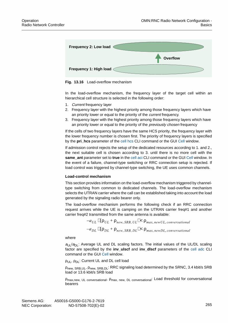
OperationRadio Network Controller
OMN:RNC Radio Network Configuration -Basics
Siemens AG: A50016-G5000-G176-2-7619NEC Corporation: ND-57508-702(E)-02 265
Fig. 13.16 Load-overflow mechanism
In the load-overflow mechanism, the frequency layer of the target cell within anhierarchical cell structure is selected in the following order:
1. Current frequency layer2. Frequency layer with the highest priority among those frequency layers which have
an priority lower or equal to the priority of the current frequency.3. Frequency layer with the highest priority among those frequency layers which have
an priority lower or equal to the priority of the previously chosen frequency
If the cells of two frequency layers have the same HCS priority, the frequency layer withthe lower frequency number is chosen first. The priority of frequency layers is specifiedby the pri_hcs parameter of the cell hcs CLI command or the GUI Cell window.
If admission control rejects the setup of the dedicated resources according to 1. and 2.,the next suitable cell is chosen according to 3. until there is no more cell with thesame_ant parameter set to true in the cell aci CLI command or the GUI Cell window. Inthe event of a failure, channel-type switching or RRC connection setup is rejected. Ifload control was triggered by channel-type switching, the UE uses common channels.
Load-control mechanism
This section provides information on the load-overflow mechanism triggered by channel-type switching from common to dedicated channels. The load-overflow mechanismselects the UTRAN carrier where the call can be established taking into account the loadgenerated by the signaling radio bearer only.
The load-overflow mechanism performs the following check if an RRC connectionrequest arrives while the UE is camping on the UTRAN carrier freq#1 and anothercarrier freq#2 transmitted from the same antenna is available:
where
aUL/aDL: Average UL and DL scaling factors. The initial values of the UL/DL scalingfactor are specified by the inv_ulscf and inv_dlscf parameters of the cell adc CLIcommand or the GUI Cell window.
ρUL, ρDL: Current UL and DL cell load
ρnew, SRB,UL, ρnew, SRB,DL: RRC signaling load determined by the SRNC, 3.4 kbit/s SRBload or 13.6 kbit/s SRB load
ρmax,new, UL conversational, ρmax, new, DL conversational: Load threshold for conversationalbearers
Overflow
Frequency 2: Low load
Frequency 1: High load
a– UL ρUL ρnew SRB UL, ,+( )⋅ ρmax newUL conversational, ,<
a– DL ρDL ρnew SRB DL, ,+( )⋅ ρmax newDL conversational, ,<

OMN:RNC Radio Network Configuration -Basics
OperationRadio Network Controller
266Siemens AG:A50016-G5000-G176-2-7619NEC Corporation:ND-57508-702(E)-02
If the inequation is satisfied, the RRC connection is established on freq#1. Afterward,admission control decides if the load for the new traffic bearer ρmax,new, UL/DL traffic classcan be accepted:
If this inequation is not satisfied, a RAB assignment failure occurs.
Enhanced load-control mechanism
This section provides information on the enhanced load-control mechanism invoked byload control and UE Differentiation during the RRC connection establishmentprocedure.
The enhanced load-control mechanism is based on the Load-control mechanism. Ittakes, however, into account the load of the traffic bearer since the load associated tothe traffic bearer can be much higher than the load associated to the signaling bearer.
The usage of traffic-class-specific thresholds and the margin value “2* MUL/DL”minimizes the RAB-blocking probability where the RAB-related RRC connection can beredirected to inter-frequency carriers which may be less loaded.
If the load-overflow mechanism is triggered by load control and UE Differentiation, thefollowing formulas are used:
where
aUL/aDL: Average UL and DL scaling factors
ρUL, ρDL: Current UL and DL cell load
ρnew,SRB, UL, ρnew, SRB,DL: RRC signalling load determined by the SRNC, 3.4 kbit/s SRBload or 13.6 kbit/s SRB load
MUL/MDL: Margin specified by system data for Load-Based Bit Rate Adaptation. Defaultvalue is the theoretical load of UDI calls.
ρmax,new, UL traffic class, ρmax, new, DL traffic class: Traffic-class specific load thresholdsrelated to the cause value reported in the “Establishment Cause” IE of the RRCCONNECTION REQUEST message.
a– UL ρUL ρnew bearer UL, ,+( )⋅ ρmax newULtraffic class,<
a– DL ρDL ρnew bearer DL, ,+( )⋅ ρmax newDLtraffic class,<
a– UL ρUL ρnew SRB UL, , 2 M UL⋅+ +( )⋅ ρmax newULtraffic class,<
a– DL ρDL ρnew SRB DL, , 2 M DL⋅+ +( )⋅ ρmax newDLtraffic class,<

OperationRadio Network Controller
OMN:RNC Radio Network Configuration -Basics
Siemens AG: A50016-G5000-G176-2-7619NEC Corporation: ND-57508-702(E)-02 267
The SRNC takes into account the “Establishment Cause” IE included in the RRCCONNECTION REQUEST message to determine the ρmax,new, UL/DL traffic classthresholds:• “Establishment Cause” IE is RAB-related:
ρmax,new, UL/DL traffic class corresponds to the traffic class or call type of the “RRC RABRelated Establishment Cause” IE:– “Originating/Terminating Conversational Call”:
ρmax,new, UL/DL traffic class corresponds to the conversational thresholdρnew,UL,Conversational / ρnew,dL,Conversational. The maximum uplink load and themaximum downlink power for new conversational bearers are specified by themul_ncrb and mdlp_ncrb parameters of the cell adc CLI command or the GUICell window.
– “Originating/Terminating Streaming Call”:ρmax,new, UL/DL traffic class corresponds to the streaming threshold ρnew,UL,Streaming/ ρnew,dL,Streaming. The maximum uplink load and the maximum downlink powerfor new streaming bearers are specified by the mulfnsrb and mdlp_nsrbparameters of the cell adc CLI command or the GUI Cell window.
– “Originating/Terminating Interactive Call”:ρmax,new, UL/DL traffic class corresponds to the admissible UL loads and theadmissible DL power for new 8 kbit/s interactive bearers specified by themul_npirb and mdlp_npirb parameters of the cell adc CLI command or the GUICell window.
– “Originating/Terminating Background Call”: ρmax,new, UL/DL traffic classcorresponds to the admissible UL loads and the admissible DL power for new8 kbit/s background bearers specified by the mul_npbrb , and mdlp_npbrbparameters of the cell adc CLI command or the GUI Cell window.
– “Emergency Call”: ρmax,new, UL/DL traffic class corresponds to the admissibleuplink load and downlink power for emergency calls specified by the mul_emgand mdlp_emg parameters of the cell adc CLI command or the GUI Cell window.
• “Establishment Cause” IE is NAS-relatedρmax,new, UL/DL traffic class corresponds to the NAS admission control threshold that isnot configurable by the operator.
NAS-related establishment causes are:– “Registration”– “Detach”– “Originating High Priority Signalling”– “Terminating High Priority Signalling”– “Inter-RAT cell re-selection”– “Inter-RAT cell change order”– “Call re-establishment”
• “Establishment Cause” IE is neither NAS-related nor RAB-relatedρmax,new, UL/DL traffic class corresponds to the SRB admission control threshold that isnot configurable by the operator.

OMN:RNC Radio Network Configuration -Basics
OperationRadio Network Controller
268Siemens AG:A50016-G5000-G176-2-7619NEC Corporation:ND-57508-702(E)-02
13.5.1.2 Load-Balancing MechanismThe load-balancing procedure balances the uplink and downlink loads of all frequenciesto achieve a similar coverage for all frequencies and all link directions. The load isevaluated by the admission control function depending on the interference and powerlevels within the system.
The uplink and the downlink load values which are used for load balancing are definedas follows:
where {aUL,aDL}are the average UL and DL scaling factors and {ρUL, ρDL} are the currentUL and DL cell load, see Basic Algorithm of Admission Control.
In the load-balancing mechanism, the target cell is selected by comparing the load ofthe current cell with the loads of the potential target cells:
max(LoadUL,j; LoadDL,j) < max (LoadUL,k; LoadDL,k): for all k ≠ j
where j is the selected cell and k denotes other potential target cells.
If admission control rejects the setup of the dedicated resources in the chosen cell, theongoing procedure fails, in other words no retry to another cell is done.
Fig. 13.17 shows a load balancing mechanism for a macro - macro scenario where cellsof two frequency layers have identical coverage and therefore are assumed to provideidentical QoS.
Fig. 13.17 Load-balancing mechanism
LoadUL aULρUL=
LoadDL aDLρDL=
Frequency 2: Medium load
Frequency 1: Medium load

OperationRadio Network Controller
OMN:RNC Radio Network Configuration -Basics
Siemens AG: A50016-G5000-G176-2-7619NEC Corporation: ND-57508-702(E)-02 269
13.5.2 Basic Mechanisms for Inter-Frequency Handover ControlIf the UE is in soft handover state, in other words the active set consists of more thanone cell, the adjacent cells of all active-set cells are evaluated as potential handovertargets. For more information on the adjacent cell list to be used for inter-frequencyhandover see Adjacent Cell List.
Characteristics of adjacent UTRAN cells are defined by the cell aci CLI command or theCell window. The adjacent cell information indicator acii specifies whether an adjacentUTRAN cell can be used for selection/reselection (srs ), handover (ho ) or both proce-dures (all ). If it is set to srs , then this cell is not considered as an inter-frequency han-dover candidate.
The inter-frequency adjacent cells of the cells which are currently in the active set andcontrolled by a different RNC must be known for inter-frequency handover procedurewith involvement of the Iur is supported. Therefore the RNC - if it acts as a DRNC -includes inter-frequency adjacent neighbor cell information in the related Iur messagestoward the SRNC, in other words the RNSAP RL SETUP RESPONSE and the RNSAPRL ADDITION RESPONSE messages.
Two hard handover procedures are supported by the RNC:• Timing Maintained Handover
The uplink transmission timing and the connection frame number in the UE is notchanged. The SRNC must know the timing difference between the connection framenumber and the system frame number of the target cell.
• Timing Re-Initialized HandoverA new physical-channel timing for the UE and the involved Node Bs can be set. Thenew timing is chosen freely by the RNC. Timing re-inclosed handover resets the UEsUL transmission timing by sending a new DPCH default offset value.
Timing maintained handover is used for blind handover. In all other cases timing re-ini-tialized handover is performed.
In the event of an intra-Node B inter-frequency handover, the Node B decides on the Iubtransport bearer of the newly established radio link depending on the handoverprocedure:• Timing maintained handover
The existing transport bearer is used for the new radio link.• Timing re-initialized handover
A second transport bearer is established on the Iub interface because the SRNCrequires a different internal Iub transport termination point. If the Iur interface isinvolved in the handover procedure, a second Iur transport bearer is established.

OMN:RNC Radio Network Configuration -Basics
OperationRadio Network Controller
270Siemens AG:A50016-G5000-G176-2-7619NEC Corporation:ND-57508-702(E)-02
13.5.3 Inter-Frequency Handover Triggered by Air-Interface ConditionInter-frequency handover in an HCS environment is attempted upon:• Reporting event 2A: Change of best frequency• Reporting event 2B: The downlink quality (CPICH Ec/No or CPICH RSCP) on the
air interface falls below the configured threshold and the quality of an adjacent cellis better than the specified threshold.
The thresholds are specified by the ifhc CLI command or the GUI Interfrequency Han-dover Control window.
Inter-frequency handover due to the condition of the air interface is triggered by:• Loss of Coverage• Adjacent-Cell Interference
Additionally an inter-frequency handover is performed if an intra-frequency handover toa reserved cell is triggered, see Restriction Control.
13.5.3.1 Loss of CoverageThe coverage of the current cell may be lost due to:• The temporary air-interface condition :
– The UE is currently in a fading gap or in a shadowed area.– The distance to the antenna together with a high load situation causes a rapid
decrease of the receive signal from the Node B.• The limited coverage due to network topology
A HCS environment is most likely limited to a specific area, for example an urbanarea. At the border of the HCS environment the coverage of one or more frequencyarea ends.
Fig. 13.18 and Fig. 13.19 provide examples for the two loss-of-coverage scenarios. Inboth cases an inter-frequency handover to a frequency layer with extended coveragewill be attempted.
Fig. 13.18 Coverage-triggered handover due to temporary air-interface conditions
Fig. 13.19 Coverage-triggered handover due to border of frequency layers
RF1
RF2
RF3
Coverage gap
RF1
RF2
RF3

OperationRadio Network Controller
OMN:RNC Radio Network Configuration -Basics
Siemens AG: A50016-G5000-G176-2-7619NEC Corporation: ND-57508-702(E)-02 271
13.5.3.2 Adjacent-Cell InterferenceAdjacent-cell interference occurs if a UE that is connected to a cell of a certain frequencylayer comes near a cell of a different frequency layer. Fig. 13.20 shows adjacent-cellinterference in an HCS scenario with micro-macro deployment.
If interference between adjacent cells occurs• the UE demands higher downlink power from the (macro) cell it is connected to.
If several UEs demand a higher downlink power at the same time, the total DL powerof the cell increases and the overall capacity is reduced.
• the uplink interference at the adjacent cell is increased and therefore interfering theUEs connected to that cell.
Fig. 13.20 Adjacent-cell interference triggered handover
13.5.4 Handover DecisionThe reporting events that trigger inter-frequency or inter-system handover depend onthe reason for bad radio conditions:• End of current frequency coverage: Event 2D, 2D’
The following 2D triggers are signaled:– 2D: Trigger for inter-frequency handover– 2D’: Trigger for inter-system handover
(In addition 2D’’ is configured if Combined measurements for inter-system han-dover are active.)
• Loss of coverage due to a fading gap: Event 2B• Adjacent channel interference: Event 2A• Inter-System handover: Event 3A
(In addition 3A’ is configured if Combined measurements for inter-system handoverare active.).
Upon reception of event 2D, a Timing Maintained Handover is attempted prior to the ini-tiation of inter-frequency measurements if there are any adjacent inter-frequency cellson the same antenna and blind handover is enabled.
If the RNC receives an event 2A or 2B report after reception of an Event 2D report, Tim-ing Re-Initialized Handover is triggered.
Macro cell
Micro cell
UE

OMN:RNC Radio Network Configuration -Basics
OperationRadio Network Controller
272Siemens AG:A50016-G5000-G176-2-7619NEC Corporation:ND-57508-702(E)-02
If the RNC receives an Event 2F report after reception of an Event 2D report, thehandover procedure is terminated.
Measurements with the same event types, for example events 2D/2D’ or 2F/2F’ mustuse different measurement control messages while different event types may beconfigured in a single measurement control message.
An inter-system handover is performed after the reception of event 3A. The measure-ments 2A, 2B, and 2F, which are always configured together, are signaled in onemeasurement control message. If the measurement control fails, compressed mode (ifactive) is stopped and the UE stays on the current channels. Furthermore, measure-ment 2D is stopped and measurements 2D’/2F’ are stopped and reactivated if active.
Two admission control thresholds are used for inter-frequency handover, one for newbearers and one for soft/softer handovers. The former is normally lower than the latterone. For coverage-triggered handovers due to temporary air-interface conditions, thesoft/softer handover threshold is used.
The cell selection and reselection quality measure is indicated by the csrqm=ecn0 /rscp parameter of the cell iub CLI command or the GUI Cell window. CPICH Rx Ec/N0as quality measure is recommended, since CPICH Rx RSCP is not able to detect badradio conditions due to high adjacent channel interference.
Furthermore, it is recommended to switch the CPICH RSCP reporting on by therind_frscp parameter of the ifhc CLI command or the GUI Interfrequency HandoverControl window. Thus, bad radio conditions due to coverage problems and bad radioconditions due to adjacent channel interference can be distinguished.The report, how-ever, is not used in the algorithm.
Whether the cell with the best measured Ec/I0 lies in the frequency band next to thecurrent frequency band is determined by comparing the UL and DL UARFCN values ofthe measured cell with the corresponding values of the cells in the active set. If the ULand/or the DL UARFCN values are less than 30 different to the corresponding value(s)of one of the cells in the active set, the condition “the frequency bands are lying next toeach other” is valid.
For more information on the measurement quantity for frequency quality estimatemq_fqe see the ishc CLI command or the GUI Intersystem Handover Control window.
13.5.4.1 Events 2D and 2D’The measurements for event 2D and 2D’ are used to detect bad radio conditions bymeasuring the quality of the current frequency:• Event 2D triggers inter-frequency handover and, if the trigger conditions are met,
compressed mode for inter-frequency handover.• Event 2D’ triggers inter-system handover and, if the trigger conditions are met,
compressed mode for inter-system handover.(In addition 2D’’ is configured if combined measurements for inter-system handoverare active.)
Compressed mode for inter-system and inter-frequency measurements are not config-ured to be active at the same time. Inter-frequency handover or inter-system handovercan be prioritized by setting the measurement thresholds for Event 2D and 2D’. There-fore, the trigger events 2D and 2D’ have different thresholds with different measurementIds in different measurement controls.

OperationRadio Network Controller
OMN:RNC Radio Network Configuration -Basics
Siemens AG: A50016-G5000-G176-2-7619NEC Corporation: ND-57508-702(E)-02 273
Inter-frequency and inter-system measurements are stopped, if the quality of the currentfrequency is above a certain threshold. Trigger 2F is used to stop the inter-frequencymeasurements and 2F’ to stop the inter-system measurements.
The parameters specified for the inter-frequency measurements 2D and 2F are thethreshold of the currently used frequency thruf_2d / thruf_2f , the weighting factorwuf_2d / wuf_2f , the hysteresis hyst_2d / hyst_2f and the time to trigger tmtrg_2d /tmtrg_2f . All parameters are specified by the ifhc CLI command or the GUIInterfrequency Handover Control window. For more information on event 2D’ see BasicMechanism for Inter-System Handover.
The triggers events 2D and 2D’ are activated for UEs switched to DCH after successfulhard handover or active set update:• Event 2D activation criteria
Measurement 2D is started if all of the following conditions are satisfied:– Measurement 2D is not active– The UE supports event 2D– At least on adjacent inter-frequency cell is available that is a candidate as target
cell for an inter-frequency handover.Candidates as target cells for an inter-frequency handover are those adjacent inter-frequency cells with the adjacent cell information indicator acii of the cell aci CLIcommand or the GUI Cell window set to handover (ho ), or handover andselection/reselection (all ).regardless of the value of the same_ant parameter in thecell aci CLI command or the GUI Cell window.If, however, inter-frequency handover with inter-frequency measurements is notallowed, only adjacent inter-frequency cells with the same_ant parameter set totrue in the cell aci CLI command or the GUI Cell window are taken into account.
• Event 2D’ activation criteriaMeasurement 2D’ is started if all of the following conditions are satisfied:– The UE has the capability to handover to GSM.– At least one of the cells of the active set has a GSM neighbor cell belonging to the
band as specified by the preferred GSM band parameter fband_gsm of the rncCLI command or the GUI RNC window.
Measurement 2D’ can be started for UEs with one of the following RAB combination:– CS RAB– PS RAB and the operator-configurable “Cell Change Order Allowed” parameter is
set to “TRUE”For more information on the cell change order mechanism see Cell Change Order.
A Timing Maintained Handover is attempted prior to the initiation of inter-frequencymeasurements if there are any adjacent inter-frequency cells on the same antenna andblind handover is enabled.
If a UE does not support 2D and 2D’ measurements at the same time, the RNC willactivate the event 2D or 2D’ according to the setting of the IF/IS measurement controlorder parameter mmco of the rnc CLI command or the GUI RNC window.

OMN:RNC Radio Network Configuration -Basics
OperationRadio Network Controller
274Siemens AG:A50016-G5000-G176-2-7619NEC Corporation:ND-57508-702(E)-02
Failure handling for event 2D
Two settings are available for the behavior of the RNC upon reception of an RRCMEASUREMENT CONTROL FAILURE message as response to a measurementcontrol message for event 2D:• First setting
If the setup of 2D measurement fails, the RNC checks if 2D’ measurement is alreadyactive (regardless of the failure cause):– Measurement 2D’ is active: The RNC assumes that the UE can not support the
activation of multiple 2D measurements at the same time. Therefore, the activa-tion of 2D measurements is aborted but the call is retained. If any of the measure-ments 2A, 2B, and 2F are active, they are stopped and compressed mode isdeactivated (if active).
– Measurement 2D’ is not active: The RNC sets the UE context parameter “2dMeasurement Support” to “FALSE” to prevent new attempts to start measurement2D or 2D’. The activation of inter-frequency measurement is aborted but the callis retained.
If the modification/release of 2D measurement fails, the RNC sets the UE contextparameter “2d Measurement Support” to “FALSE” to prevent new attempts to startmeasurement 2D or 2D’. The activation of inter-frequency measurements is abortedbut the call is retained.
• Second setting
If the failure cause is “unsupported measurement” or “configuration unsupported”,the RNC checks whether or not 2D’ measurement is already active:– Measurement 2D’ is active: The RNC assumes that the UE can not support the
activation of multiple 2D measurements at the same time. Therefore, the activa-tion of 2D measurement is aborted but the call is retained. If any of the measure-ments 2A, 2A’, 2B, and 2F are active, they are stopped and compressed mode isdeactivated (if active).
– Measurement 2D’ is not active: The RNC sets the UE context parameter “2dMeasurement Support” to “FALSE” to prevent new attempts to start 2D or 2D’measurement. The activation of inter-frequency measurement is aborted but thecall is retained.
If the failure cause was any other value, the RNC initiates the release of the call bysending an IU RELEASE REQUEST message to all connected CNs. The callrelease is initiated because other cause values, such as protocol error, only occur inthe event of a serious software error.If the modification/release of 2D measurement fails, the RNC initiates the release ofthe call by sending an IU RELEASE REQUEST message to all connected CNs.

OperationRadio Network Controller
OMN:RNC Radio Network Configuration -Basics
Siemens AG: A50016-G5000-G176-2-7619NEC Corporation: ND-57508-702(E)-02 275
Handling of early UEs
In general, the RNC skips the measurement control information for event 2D if both ofthe following conditions are true:• Inter-frequency handover without compressed mode is disabled by the ifho_wocm
parameter of the rnc CLI command or the GUI RNC window.• Compressed mode and 2AB measurements for hierarchical cell structures are
disabled by the ecm_2abm parameter of the rnc CLI command or the GUI RNC.
A special configuration can be used for early UEs which do not support inter-frequencymeasurements and indicate as measurement capability that they do not requirecompressed mode for FDD inter-frequency measurements. The configuration can beused if no other UEs are in the network which really do not require compressed modefor inter-frequency measurements and therefore would indicate the same measurementcapability.
The RNC detects the early UEs by evaluation of the provided measurement capabilityinformation, i.e. the early UEs do not require compressed mode for FDD inter-frequencymeasurements in UL/DL. For this early UEs, the RNC assumes the ecm_2abm param-eter as set to FALSE independent of the setting in the database. For all other UEs, how-ever, the value specified in the database is used.
In this configuration, the RNC skips measurement control information for event 2D if allof the following is true:• Inter-frequency handover without compressed mode is disabled by the ifho_wocm
parameter of the rnc CLI command or the GUI RNC window.• “UE Capability Need for Uplink Compressed Mode FDD measurement” == FALSE• “UE Capability Need for Downlink Compressed Mode FDD measurement” ==
FALSE
Therefore, the early UE does not report event 2D to the RNC and thus cannot trigger aninter-frequency handover. Event 2D’ for inter-system handover, however, is sent to theUE. Therefore, the UE can report event 2D’ which triggers inter-system measurements(event 3A).
In the event of UMTS coverage outage, an inter-system handover is triggered for thisearly UE while for all other UEs an inter-frequency handover can be applied if a secondfrequency provides coverage.
13.5.4.2 Events 2A and 2BTiming Re-Initialized Handover is triggered if the RNC receives an event 2A or 2B reportafter the reception of an event 2D report and compressed mode for inter-frequencymeasurements is active:• Event 2A
Inter-frequency handover is performed to the cell with the best measured CPICHEc/N0. If this inter-frequency handover fails, the UE remains in the current frequencyand the inter-frequency measurements continue.
• Event 2BInter-frequency handover is performed to the cell with the best measured CPICHEc/N0. If this inter-frequency handover fails, inter-frequency handover is performedto the cell with the best measured CPICH Ec/N0 on another not yet probed frequen-cy. If this inter-frequency handover fails, the UE remains in the current frequency andthe inter-frequency measurements continue.

OMN:RNC Radio Network Configuration -Basics
OperationRadio Network Controller
276Siemens AG:A50016-G5000-G176-2-7619NEC Corporation:ND-57508-702(E)-02
The parameters specified for event 2A are the weighting factor wuf_2ad , the hysteresishyst_2ad , the time to trigger tmtrg_2ad , and the weighting factor of a frequency not yetused wnouf_2ad .
The parameters for the old event 2A are invalid but please input some values within therange: wuf_2a , hyst_2a , tmtrg_2a and wnouf_2a .
The following parameter are specified for event 2B: The threshold of the currently usedfrequency thruf_2b , the weighting factor wuf_2b , the hysteresis hyst_2b , time to trig-ger tmtrg_2b , the threshold of a frequency not yet used thrnouf_2b , and the weightingfactor of a frequency not yet used wnouf_2b .
All parameters are specified by the ifhc CLI command or the GUI Interfrequency Han-dover Control window.
A user in a Macro cell that moves toward a Node B of an adjacent Micro cell has to bedropped if he comes to close to the Micro Node B and cannot be hand overed to thisMicro cell. The trigger 2A is used to trigger a handover attempt at the possibility for theuser to handover. If this handover also fails the user is dropped, since he would other-wise degrade the whole adjacent Micro cell.
13.5.5 Timing Maintained HandoverDuring a timing maintained handover, the uplink transmission timing and the connectionframe number in the UE is not changed. Therefore, the SRNC must know the timingdifference between the connection frame number and the system frame number of thetarget cell.
Based on the timing maintained handover procedure, blind handovers are performed. Ablind handover is an inter-frequency handover that does not trigger inter-frequencymeasurements on the target cell.
A blind handover is attempted if inter-frequency handover without compressed mode isenabled by the ifho_wocm parameter of the rnc CLI command or the GUI RNC window.A blind handover is always a handover to a cell on the same Node B, in other words withthe same_ant parameter set to true in the cell aci CLI command or the GUI Cell windowfor at least one inter-frequency neighbor cell. A blind handover is attempted prior to theinitiation of inter-frequency measurements. The Iur interface is not involved in a blindhandover.
The RNC notifies the UE of the 2D report conditions via a MEASUREMENT CONTROLmessage.
The UE monitors the adjacent cell based on this conditions. Event 2D occurs if the fol-lowing equations are valid for the time to trigger tmtrg_2d specified by the ifhc CLI com-mand or the GUI Interfrequency Handover Control window:• Quality of a carrier j
Qcarrierj 10 M carrierjlog⋅ W j 10 M iji 1=
N Aj
∑
log⋅ ⋅ 1 W j–( ) 10 M bestjlog⋅ ⋅+= =

OperationRadio Network Controller
OMN:RNC Radio Network Configuration -Basics
Siemens AG: A50016-G5000-G176-2-7619NEC Corporation: ND-57508-702(E)-02 277
• Quality of the currently used carrier
where
Qcarrierj is the quality of carrier j.
Mcarrierj is the measurement result of carrier j.
Mij is the measurement result for the active set cell of carrier j.
NAj is the number of cells currently in the active set of carrier j.
Mbestj is the measurement result of the strongest cell in the active set of carrier j.
Wj is the weighting factor wuf_2d used for event 2D, the weighting factor of carrier j.
Tused2D is the threshold of the currently used frequency for event 2D thruf_2d
H2D is the hysteresis hyst_2d for event 2D
All parameters are specified by the ifhc CLI command or the GUI Interfrequency Han-dover Control window.
The UE reports the event 2D to the RNC via a MEASUREMENT REPORT message.The RNC checks if there are target cells on the same antenna and blind handover isenabled. If target cells are found, the RNC selects a cell randomly to perform a blindhandover. Blind handover procedureFig. 13.22 shows the blind handover procedure.
If the blind handover fails and another cell satisfies the conditions for a blind handover,one retry is performed on another cell under the same Node B. If this retry fails or thereis no other suitable target cell, a Timing Re-Initialized Handover is triggered. For moreinformation on event 2D, see Events 2D and 2D’.
Fig. 13.21 shows the basic algorithm for a blind handover.
Fig. 13.21 Algorithm for a blind handover
Qused T used2D H 2D 2⁄–≤
Qcarrierj
Tused2D H2D
time
time to trigger
Event 2D Event 2Ddetected reported -> handover triggered
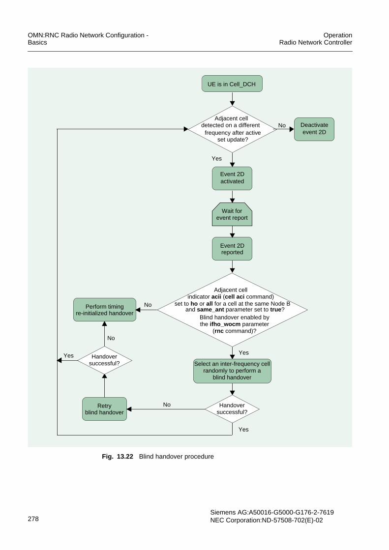
OMN:RNC Radio Network Configuration -Basics
OperationRadio Network Controller
278Siemens AG:A50016-G5000-G176-2-7619NEC Corporation:ND-57508-702(E)-02
Fig. 13.22 Blind handover procedure
UE is in Cell_DCH
Event 2Dreported
Adjacent cellNo
Yes
Yes
Perform timingre-initialized handover
No
detected on a differentfrequency after active
activatedEvent 2D
Handoversuccessful?
Yes
No
set update?event 2D
Deactivate
Wait forevent report
Handoversuccessful? Select an inter-frequency cell
randomly to perform ablind handover
Yes
NoRetryblind handover
Adjacent cellindicator acii (cell aci command)
and same_ant parameter set to true ?Blind handover enabled bythe ifho_wocm parameter
(rnc command)?
set to ho or all for a cell at the same Node B

OperationRadio Network Controller
OMN:RNC Radio Network Configuration -Basics
Siemens AG: A50016-G5000-G176-2-7619NEC Corporation: ND-57508-702(E)-02 279
13.5.6 Timing Re-Initialized HandoverIn a timing re-initialized handover, compressed mode is activated to obtain informationon the target cell such as the transmission timing.
The timing re-initialized handover procedure is performed in the event of:• A failure of a blind handover, see Timing Maintained Handover• A handover between cells of different coverage• A handover between cells under different Node Bs• A handover between cells under different RNCs
Fig. 13.23 shows the timing re-initialized handover procedure. The RNC notifies the UEof the conditions for the reporting of event 2D via a MEASUREMENT CONTROLmessage if the condition criteria are fulfilled. The UE monitors the adjacent cells basedon this conditions. If event 2D occurs, the UE reports it to the RNC via a MEASURE-MENT REPORT message. For more information on the algorithm to detect event 2Dsee Timing Maintained Handover.
The RNC checks whether or not the UE supports compressed mode for inter-frequencymeasurements and activates it if it is supported. Furthermore, the RNC notifies the UEof the conditions for event 2B, 2F, and 2A via MEASUREMENT CONTROL messages.For more information on the events to trigger a timing re-initialized handover see Events2A and 2B.
The UE monitors the adjacent cells based on the conditions received while compressedmode is active. If the UE detects event 2A or 2B, it reports this event to the RNC via aMEASUREMENT REPORT message. The RNC performs a timing re-initializedhandover. The handover procedure is terminated if the RNC receives an event 2F reportafter the reception of an event 2D report.
Compressed mode and 2AB measurements for hierarchical cell structures are enabledby the ecm_2abm parameter of the rnc CLI command or the GUI RNC.
When a timing re-initialized inter-frequency fails, the procedure is retried only once if thehandover was triggered by event 2B and there are other targets for an inter-frequencyhandover.

OMN:RNC Radio Network Configuration -Basics
OperationRadio Network Controller
280Siemens AG:A50016-G5000-G176-2-7619NEC Corporation:ND-57508-702(E)-02
Fig. 13.23 Timing re-initialized handover procedure
UE is in Cell_DCH
Adjacent cellNo
Yes
acii (cell aci )
Yes
No
detected on a differentfrequency after active
Event 2D activated
Handoversuccessful?
Yes
Yes
set update?event 2D
Deactivate
Wait for event report
same_ant set to true ?Blind handover enabled by
ifho_wocm (rnc )?
set to ho or all for a cell
Handoversuccessful?
Yes
No
Timing re-initializedhandover
Deactivate compressed modeand measurements for the
events 2A, 2B and 2F(if active)
Perform
handover
Yes at the same Node B and
Compressed modeenabled by ecm_2abm
parameter of (rnc )
Event 2D reported
Yes
Activate compressed mode
Wait for event report
Event 2Aor 2B reported?
Yes
Handover byevent 2B failed?
No
(during compressed mode)
No
Retry
handover
Handoversuccessful?
Yes No
and events 2A, 2B, 2F
Event 2Freported?
Deactivatecompressed
mode and events2A and 2B
No
No
Exit GSMadjacent
cells?Timing re-initialized
inter-systemhandover
Perform Yes
No
No
blind

OperationRadio Network Controller
OMN:RNC Radio Network Configuration -Basics
Siemens AG: A50016-G5000-G176-2-7619NEC Corporation: ND-57508-702(E)-02 281
The following sections describe how the UE detects event 2A or 2B by comparing themeasurement results of the cell on the currently used frequency with that of the non-used frequency based on the parameters included in the MEASUREMENT CONTROLmessage.
Event 2A
The following condition must be satisfied to replace the cell on the frequency that iscurrently notified as the best one by a cell on another frequency:
where:
QBest is the carrier quality of the cell on that frequency that is currently notified as thebest
QNew is the carrier quality of a cell on another frequency
H2A is the hysteresis for event 2A hyst_2ad specified by the ifhc CLI command or theGUI Interfrequency Handover Control window.
The UE reports event 2A to the RNC if the new cell satisfies the above condition for theperiod of time specified by the time to trigger for event 2A tmtrg_2ad .
Fig. 13.24 shows the algorithm for timing re-initialized handover triggered by event 2A.
Fig. 13.24 Algorithm for a timing re-initialized handover triggered by event 2A
Furthermore, the weighting factor wuf_2ad and the weighting factor of a frequency notyet used wnouf_2ad are specified by the ifhc CLI command or the GUI InterfrequencyHandover Control window.
QNew QBest H 2A 2⁄+≥
H2A
Event 2A Event 2Adetected -> handover triggered
Best frequency
New frequency
timetime to trigger
Qcarrier

OMN:RNC Radio Network Configuration -Basics
OperationRadio Network Controller
282Siemens AG:A50016-G5000-G176-2-7619NEC Corporation:ND-57508-702(E)-02
Event 2B
The cell on the currently used frequency is replaced by a new cell on another frequencyif both of the following conditions are satisfied:
where:
QNonused is the carrier quality of a currently not used frequency.
TNonused 2B is the threshold of the not used frequency for event 2B thrnouf_2b, that isthe threshold for the carrier quality of a currently not used frequency.
H2B is the hysteresis for event 2B hyst_2b.
Qused is the carrier quality of the currently used frequency.
Tused 2B is the threshold of the used frequency for event 2B thruf_2b , that is thethreshold for the carrier quality of the currently used frequency.
Furthermore, the weighting factor for the currently used frequency wuf_2b and a notused frequency wnouf_2b are specified for event 2B.
All parameters are specified by the ifhc CLI command or the GUI Interfrequency Han-dover Control window.
The UE report event 2B to the RNC if the new cell satisfies the above conditions for thetime to trigger specified by the tmtrg_2b parameter of the ifhc CLI command or the GUIInterfrequency Handover Control window.
Fig. 13.25 shows the algorithm for a timing re-initialized handover triggered byevent 2B.
Fig. 13.25 Algorithm for a timing re-initialized handover triggered by event 2B
QNonused T Nonused H 2B 2⁄+≥
QUsed T Used2B H 2B 2⁄–≤
H2B/2
Event 2B Event 2B reporteddetected -> handover triggered
Used frequency
Not used frequency
time
time to trigger
Qcarrier
H2B/2
Tnonused 2B
Tused 2B

OperationRadio Network Controller
OMN:RNC Radio Network Configuration -Basics
Siemens AG: A50016-G5000-G176-2-7619NEC Corporation: ND-57508-702(E)-02 283
13.6 Inter-System Handover ControlThe handover functions supported by inter-system handover control are:• UMTS to GSM/GPRS hard handover
– User of CS and CS+PS services move to GSM– User of PS services move to /GPRS
• GSM to UMTS hard handover
Handover mechanisms from UMTS to GSM are necessary if a UE leaves a UMTScoverage area while it has an active connection. Handover from UMTS to GSM istriggered when the quality of the UMTS frequency is below a certain threshold and thequality of the GSM frequency is above a certain threshold.
Handover of PS services from UMTS to GPRS is based on forward cell reselection andis initiated by a UE in Cell_FACH, Cell_PCH, or URA_PCH states. The UE performs aninter-system routing area update and accesses the GPRS system based on inter-system measurement results. In Cell_DCH state, the Cell Change Order proceduretransfers a UTRAN PS RAB connection to a GSM/GPRS cell under the control of theUTRAN.
Handover and relocation of CS services from UMTS to GSM is based on hard handoverand is triggered by UTRAN.
This section provides information on the following topics and related commands:• Basic Mechanism for Inter-System Handover
– ishc CLI command or the GUI Intersystem Handover Control window• Cell Change Order
– ishc CLI command or the GUI Intersystem Handover Control window– cell iub CLI command or the GUI Cell window– cell agci CLI command or the GUI Cell window– egc CLI command or via the GUI External GSM Cell window
Characteristics of external GSM cells are specified by the egc CLI command or via theGUI External GSM Cell window.
Example
cre ishc mq_fqe=rscp ftce=2 thruf_2dug=-80 wuf_2dug=0hyst_2dug=0.5 tmtrg_2dug=200 thruf_2f=-70 wuf_2f=0 hyst_2f=0.5tmtrg_2f=640 mq_uqe=rscp ftce_utran=2 ftce_gsm=0 bsic_veri=rqrcco_alwd=true thrown_3a=-85 throth_3a=-90 w_3a=0 hyst_3a=0tmtrg_3a=200
The cre ishc CLI command specifies data for inter-system handover control. mq_fqespecifies the measurement quantity to estimate the quality of the current frequency(ecn0 : CPICH Ec/N0, rscp : CPICH RSCP). ftce indicates the filter coefficient.
The parameters specified for the inter-system measurements 2D’ and 2F’ are thethreshold of the currently used frequency thruf_2dug / thruf_2f , the weighting factorwuf_2dug / wuf_2f , the hysteresis hyst_2dug / hyst_2f , and the time to triggertmtrg_2dug / tmtrg_2f .
i NOTE2D/2F measurements and related parameters for inter-system handover differ from2D/2F measurements and parameters used for inter-frequency handover. In thefollowing, the trigger which are used for inter-frequency handover are called 2D/2F andthe trigger which are used for inter-system handover are called 2D’/2F’ and 2D’’/2F’’ ifapplied.

OMN:RNC Radio Network Configuration -Basics
OperationRadio Network Controller
284Siemens AG:A50016-G5000-G176-2-7619NEC Corporation:ND-57508-702(E)-02
mq_uqe specifies the measurement quantity to estimate the quality of the UTRAN. Themeasurement filter coefficient of UTRAN and GSM is indicated by ftce_utran andftce_gsm . bsic_veri specifies whether or not the Base Transceiver Station IdentityCode (BISC) needs to be verified. Whether or not cell change order is allowed isspecified by cco_alwd .
The parameters specified for event 3A are the threshold of the own system (UTRAN)thrown_3a , the threshold of the other system (GSM) throth_3a , the weighting factorw_3a, the hysteresis hyst_3a and the time to trigger tmtrg_3a .
The parameter settings for combined measurements are introduced in Combinedmeasurements for inter-system handover.
13.6.1 Basic Mechanism for Inter-System HandoverThe handover algorithm for CS-only and CS+PS traffic is based on the events 2D’, 2F’,and 3A, described in 3GPP TS25.331 “Requirements for support of radio resourcemanagement”.
The RNC starts a measurement control cycle with events 2D’ and 2F’ if all of thefollowing conditions are satisfied:• The UE has the capability to handover to GSM.• At least one of the cells of the active set has a GSM neighbor cell belonging to the
band specified by the preferred GSM band parameter fband_gsm of the rnc CLIcommand or the GUI RNC window.
• Measurement 2D’ can be started for UEs with one of the following RAB combination:– CS RAB– PS RAB and the operator-configurable “Cell Change Order Allowed” parameter is
set to “TRUE”For more information on the cell change order mechanism see Cell Change Order.
In the event of an inter-system handover, the CS call is maintained by UTRAN-con-trolled inter-system handover. The PS call is followed in the target GSM/GPRS cell byUE-controlled signaling and is released in the UTRAN at the request of the SGSN or ontime-out.
In the case of PS-only traffic, UE-controlled cell reselection is performed in Cell_FACH,Cell_PCH, and URA_PCH states or after a radio link failure. Compressed mode is nottriggered. For information on the transfer of a UTRAN PS RAB connection to aGSM/GPRS cell under the control of the UTRAN see Cell Change Order.
The UE reports event 2D’ to the RNC via a MEASUREMENT REPORT message if theCPICH measurement result of the currently used frequency falls below the thresholdthruf_2dug since the UE moves to the system border. On reception of event 2D’, theRNC sends the conditions for event 3A to the UE and starts, depending on the UE’s ca-pabilities, compressed mode for inter-system handover, see Compressed Mode. Com-pressed mode is not required if the UE features a second receiver channel. Duringcompressed mode, the UE monitors the GSM adjacent cell based on this conditions.
The UE reports event 3A to the RNC via MEASUREMENT REPORT message if theCPICH measurement result of the currently used frequency falls below the thresholdthrown_3a and that of the other system exceeds the threshold throth_3a . Afterward,the RNC triggers inter-system handover.

OperationRadio Network Controller
OMN:RNC Radio Network Configuration -Basics
Siemens AG: A50016-G5000-G176-2-7619NEC Corporation: ND-57508-702(E)-02 285
If event 2F’ is received before event 3A, compressed mode is deactivated and the UEremains in UTRAN. 2F’ is reported if the CPICH measurement result of the currentlyused frequency exceeds the threshold thruf_2f .
All parameters are specified by the ishc CLI command or the GUI Intersystem HandoverControl window.
The RAB is released and events 3A and 2D’ are deactivated if the cells in the active setdo not have adjacent GSM cells any longer due to any of the following reasons:• A cell of the active set is deleted• A cell of the active set is replaced due to a soft handover during event report waiting
period
In summary, the UE deactivates compressed mode and GSM cell measurements if anyof the following conditions is satisfied:• None of the cells of the UE’s active set has GSM neighbor cells belonging to the
preferred GSM frequency band.• The UE has no RABs in the service combination and an Iu signaling connection
exists.• The UE has no CS RAB but a PS RAB and cell change order is not allowed.• Event 2F’ has been triggered or, if combined measurements are active,
event 2F’/2F’’ has been triggered.
On the border of the coverage area, conditions for inter-frequency measurements andinter-system measurements can be satisfied at the same time. Compressed mode, how-ever, can not be active for both measurements at the same time.
If a UE does not support 2D and 2D’ measurements at the same time, the RNC activatesmeasurement 2D or 2D’ according to the setting of the IF/IS measurement control orderparameter mmco of the rnc CLI command or the GUI RNC window. For more informa-tion see Events 2D and 2D’.
Fig. 13.26 shows the inter-system handover procedure.

OMN:RNC Radio Network Configuration -Basics
OperationRadio Network Controller
286Siemens AG:A50016-G5000-G176-2-7619NEC Corporation:ND-57508-702(E)-02
Fig. 13.26 Inter-system handover procedure
Event 3Areported?
UE supportsinter-systemhandover?
UE is in Cell_DCH
Adjacent celldetected in a different
system after active set update?In the event of a PS only bearer,
cell change order enabledby cco_alwd
(ishc )?
Wait for event report
Event 2D’ reported
Activate compressed modeand event 3A
Wait for event report(during compressed mode)
Performinter-system handover
Yes
YesNo
Handoversuccessful?
Yes
No
event 2D’ (andDeactivate
Event 2F’reported?
Yes
No
No
Yes
No
3A if active)
Event 2F’reported?
No
Yes
Deactivate compressedmode and event 3A
UE moves to GSM
Wait for event report(during compressed mode)
Event 3A reported
Events 2D’, 2F’activated

OperationRadio Network Controller
OMN:RNC Radio Network Configuration -Basics
Siemens AG: A50016-G5000-G176-2-7619NEC Corporation: ND-57508-702(E)-02 287
13.6.1.1 Basic Algorithm for Inter-System HandoverThe following sections describe how the UE detects event 2D’, 3A, or 2F’ by comparingthe measurement results of the cell on the currently used frequency with that of the GSMsystem based on the parameters included in the MEASUREMENT CONTROLmessage.
For more information on the measurement quantity to estimate the carrier quality seeMeasurement Quantities.
Event 2D’
The UE reports event 2D’ to the RNC if the cell satisfies the following conditions for thetime to trigger tmtrg_2dug . Upon the reception of the report, the RNC triggers theactivation of Compressed Mode:• Quality of a carrier j
• Quality of the currently used carrier
where
Qcarrierj is the quality of carrier j.
Mcarrierj is the measurement result of carrier j.
Mij is the measurement result for the active set cell of carrier j.
NAj is the number of cells currently in the active set of carrier j.
Mbestj is the measurement result of the strongest cell in the active set of carrier j.
Wj is the weighting factor wuf_2dug used for event 2D’, the weighting factor of carrier j.
Tused2D’ is the threshold of the currently used frequency for event 2D’ thruf_2dug.
H2D’ is the hysteresis for event 2D’ hyst_2dug .
All parameters are specified by the ishc CLI command or the GUI Intersystem HandoverControl window.
Fig. 13.27 shows the basic algorithm for compressed mode.
Qcarrierj 10 M carrierjlog⋅ W j 10 M iji 1=
N Aj
∑
log⋅ ⋅ 1 W j–( ) 10 M bestjlog⋅ ⋅+= =
Qused T used2D' H 2D' 2⁄–≤

OMN:RNC Radio Network Configuration -Basics
OperationRadio Network Controller
288Siemens AG:A50016-G5000-G176-2-7619NEC Corporation:ND-57508-702(E)-02
Fig. 13.27 Activation of compressed mode for inter-system handover
Event 3A
When compressed mode for inter-system handover is active, the UE measures the ad-jacent GSM cells during the transmission gap. The UE reports event 3A and informationon the GSM cell as the handover target (RSSI measurement result and BSIC of theGSM carrier) to the RNC if the cell satisfies the following conditions for the time to triggertmtrg_3a :• Quality of a carrier j
• Quality of the currently used carrier
where
QUTRAN is the quality of the UTRAN carrier.
MUTRAN is the measurement result of the UTRAN carrier.
Mi is the measurement result for the active set cell.
NA is the number of cells currently in the active set.
Mbest is the measurement result of the strongest cell in the active set.
W is the weighting factor w_3a used for event 3A.
Tused3A is the threshold of the own system for event 3A thrown_3a, that is the thresholdfor event 3A in UMTS.
Qcarrierj
Tused2D’ H2D’
time
time to trigger
Event 2D’ Event 2D’detected reported -> compressed mode activated
QUTRAN 10 M UTRANlog⋅ W 10 M ii 1=
N A
∑
log⋅ ⋅ 1 W–( ) 10 M bestlog⋅ ⋅+= =
Qused T used3A H 3A 2⁄–≤
M OtherRAT CIOOtherRat+ T OtherRAT H 3A 2⁄+≥

OperationRadio Network Controller
OMN:RNC Radio Network Configuration -Basics
Siemens AG: A50016-G5000-G176-2-7619NEC Corporation: ND-57508-702(E)-02 289
H3A is the hysteresis for event 3A hyst_3a .
MOtherRAT is the measurement result for the GSM cell.
CIOotherRAT is the cell individual offset for the GSM cell. see Cell Individual Offset.
TotherRAT is the threshold of the other system for event 3A throth_3a , that is thethreshold for event 3A in GSM.
All parameters are specified by the ishc CLI command or the GUI Intersystem HandoverControl window.
Fig. 13.28 Algorithm for a inter-system handover triggered by event 3A
Event 2F’
The UE reports event 2F’ to the RNC if the cell satisfies the following conditions for thetime to trigger tmtrg_2f . Upon the reception of the report, the RNC triggers thedeactivation of Compressed Mode and the GSM cell measurements:• Quality of a carrier j
• Quality of the currently used carrier
where
Qcarrierj is the quality of carrier j.
Mcarrierj is the measurement result of carrier j.
Mij is the measurement result for the active set cell of carrier j.
NAj is the number of cells currently in the active set of carrier j.
Mbestj is the measurement result of the strongest cell in the active set of carrier j.
H3A/2
Event 3A Event 3A reporteddetected -> handover triggered
MOtherRAT
time
time to trigger
Qused
H3A/2
TOtherRAT
Tused
Qcarrierj 10 M carrierjlog⋅ W j 10 M iji 1=
N Aj
∑
log⋅ ⋅ 1 W j–( ) 10 M bestjlog⋅ ⋅+= =
Qused T used2F' H 2DF' 2⁄+≥

OMN:RNC Radio Network Configuration -Basics
OperationRadio Network Controller
290Siemens AG:A50016-G5000-G176-2-7619NEC Corporation:ND-57508-702(E)-02
Wj is the weighting factor wuf_2f used for event 2F’, the weighting factor of carrier j.
Tused2F is the threshold of the currently used frequency for event 2F’ thruf_2f .
H2F’ is the hysteresis for event 2F’ hyst_2f .
All parameters are specified by the ishc CLI command or the GUI Intersystem HandoverControl window.
Fig. 13.29 Deactivation of compressed mode due to event 2F’
13.6.1.2 Measurement QuantitiesThe measurement quantities to estimate the quality of the current UTRAN frequencyare:• CPICH Ec/N0
The ratio of the received energy per PN chip for the CPICH to the total receivedpower spectral density at the UE antenna connector.
• CPICH RSCPThe received signal code power for the CPICH.
The measurement and reporting quantity for GSM measurements is• GSM carrier RSSI
The measurement quantity to estimate the quality of the current UTRAN frequency is setonce per RNC by the ishc CLI command or the GUI Intersystem Handover Controlwindow:• The mq_fqe parameter is used to specify the measurement quantity for estimating
the quality of the frequency (2D/2F measurements).• The mq_uqe parameter is used to specify the measurement quantity to estimate the
quality of the UTRAN (3A measurements).
Qcarrierj
Tused2F’ H2F’
time
time to trigger
Event 2F’ Event 2F’ reporteddetected -> compressed mode deactivated

OperationRadio Network Controller
OMN:RNC Radio Network Configuration -Basics
Siemens AG: A50016-G5000-G176-2-7619NEC Corporation: ND-57508-702(E)-02 291
The appropriate measurement quantity depends on the handover scenarios in the net-work environment of an RNC. The following settings are available:• Measurement quantity CPICH Ec/N0 (mq_fqe = ecn0, mq_uqe = ecn0)• Measurement quantity CPICH RSCP (mq_fqe = rscp, mq_uqe = rscp)• Both measurement quantities CPICH Ec/N0 and CPICH RSCP (mq_fqe = rscp,
mq_uqe = rscp and thrown_3a > -24)
The measurements are updated after a soft handover if the inter_RAT neighbor cell listor the cell individual offset changes. The measurements, respectively compressedmode, are stopped if no inter_RAT neighbor cell exists or the CS RAB is deleted.
Combined measurements for inter-system handover
If both CPICH Ec/N0 and CPICH RSCP are used at the same time to estimate thequality of the current UTRAN frequency, the values of the parameters mq_fqe ,mq_uqe , and thrown_3a (threshold own system used frequency) must be:
thrown_3a > -24 AND mq_fqe = rscp AND mq_uqe = rscp
Two measurements of type 2D and 2F are configured if CPICH Ec/N0 and CPICH RSCPare used at the same time:• 2D’ and 2F’ measurements
Measurements 2D’ and 2F’ are used for measurement quantity CPICH RSCP.
Both measurements are specified by the following parameters:– thruf_2dug (threshold used frequency for event 2D)– wuf_2dug (weighting factor used frequency for event 2D)– hyst_2dug (hysteresis for event 2D)– tmtrg_2dug (time to trigger for event 2D)
• 2D’’ and 2F’’ measurementsMeasurements 2D’’ and 2F’’ are used for measurement quantity CPICH Ec/N0.
Both measurements are specified by the following parameters:– thruf_2f (threshold used frequency for event 2F)– wuf_2f (weighting factor used frequency for event 2F)– hyst_2f (hysteresis for event 2F)– tmtrg_2f (time to trigger for event 2F)
Fig. 13.30 shows how the measurements 2D’ and 2F’, 2D’’ and 2F’’ start and stopcompressed mode.

OMN:RNC Radio Network Configuration -Basics
OperationRadio Network Controller
292Siemens AG:A50016-G5000-G176-2-7619NEC Corporation:ND-57508-702(E)-02
Fig. 13.30 Triggering of compressed mode if combined measurements are used
The values for the hysteresis and the time to trigger must ensure that a ping-pong effectof 2D’, 2F’ and 2D’’, 2F’’ measurements is avoided.
Furthermore, the Inter-RAT measurements are extended by a second 3A measurement.The second measurement 3A’ is set up after 3A if the conditions for activation of 3A aremet.
Measurements 3A and 3A’ are specified as follows:• 3A measurement
Measurement 3A uses measurement quantity CPICH RSCP to estimate the qualityof the own system. The threshold for the own system is specified by the parameterthroth_3a (threshold other system for event 3A).
• 3A’ measurementMeasurement 3A’ uses measurement quantity CPICH Ec/N0 to estimate the qualityof the own system. The threshold for the own system is specified by the parameterthrown_3a (threshold own system for event 3A).
The threshold for the other RAT is set to a pre-defined value that is not configurable bythe operator, see Parameters for Inter-System Handover Control.
If the parameters are changed to activate the feature during operation, the modificationis only applicable for new calls and for ongoing calls at the next activation of 2D’, 2F’ and2D’’, 2F’’ after the modification. If the operator activates the feature and measurement2D’ is configured, the feature cannot be activated for an existing call context.
2F’’ (CPICH Ec/N0) thresholdhysteresis/2
2F’ (CPICH RSCP) thresholdhysteresis/2
2D’’ (CPICH Ec/N0) thresholdhysteresis/2
2D’ (CPICH RSCP) thresholdhysteresis/2
compressed mode on
compressed mode OFF
compressed mode OFF
compressed mode on
i NOTEThe operator must ensure that different measurement quantities are specified for themeasurements 2D’,F’ and 2D’’,2F’’. The behavior of the system is not specified if bothmeasurement 2D’,F’ and 2D’’,2F’’ are configured to use the same measurementquantity.

OperationRadio Network Controller
OMN:RNC Radio Network Configuration -Basics
Siemens AG: A50016-G5000-G176-2-7619NEC Corporation: ND-57508-702(E)-02 293
If the parameters are changed to deactivate the feature during operation while themeasurements 2D’, 2F’ and 2D’’, 2F’’ are active, the modification is only applicable fornew calls. Ongoing calls, however, still use the feature and measurements 3A and 3A’are activated if they are triggered by event 2D’ or 2D’’.
The UE can be configured to apply two concurrent quality estimations with separatedthreshold, weight, hysteresis, and time to trigger values per quality estimation. If for anyreason 2D’’, 2F’’, and 3A’ cannot be configured in the UE, no further actions concerningthe failure are taken. Early UEs of type A, B, or C might not support 2D measurements.For more information see Failure handling for event 2D.
Measurement event handling for combined measurements
Event 2D’ or event 2D’’ triggers:• 3A and 3A’ measurements• Compressed mode, if required
If measurements 3A and 3A’ are both active, either event 3A or event 3A’ can trigger theinter-RAT handover.
The conditions to stop compressed mode (if active) and measurements 3A/3A’ are:• If event 2D’ was received, event 2F’ must be triggered.• If event 2D’’ was received, event 2F’’ must be triggered.• If event 2D’ and event 2D’’ were received, both events 2F’ and 2F’’ must be triggered.
Six inter-frequency measurements can be active in the UE at the same time. Therefore,the measurements 2D, 2A, 2B, and 2F are configured during inter-frequency measure-ments and 2D, 2D’, 2D’’, 2F’ and 2F’’ are configured during inter-RAT measurements.The measurements 2D’, 2F’ and 2D’’ 2F’’ are controlled together by the RNC, in otherwords the procedures to setup, modify and delete the measurements control thecomplete set. Thus, two measurement-control messages are sent to the UE.

OMN:RNC Radio Network Configuration -Basics
OperationRadio Network Controller
294Siemens AG:A50016-G5000-G176-2-7619NEC Corporation:ND-57508-702(E)-02
13.6.2 Cell Change OrderThe purpose of the cell change order procedure is to transfer a UTRAN PS RABconnection to a GSM/GPRS cell under the control of the UTRAN. The UTRAN ordersthe UE to perform a cell change to a GSM/GPRS cell if the radio condition qualitymeasurements are below a certain threshold and the GSM radio condition quality isabove a certain threshold. For more information on the cell change order mechanismsee FD012232A - Cell Change Order.
Beside the other conditions, compressed mode and inter-system measurements arealso activated if all of the following conditions are true:• The UE is in CELL_DCH state.• The UE has only PS RAB(s) in the RAB combination.• The cell change order is active.• The UE supports the cell change order procedure.
If a signaling connection to the CS domain exists, the RNC does not trigger a cell changeorder procedure to the UE as long as this signaling connection exists.
Upon reception of event 3A, the RNC decides based on the RAB combination whetherto initiate the inter-system handover procedure or the cell change order procedure, seeTab. 13.2.
Measurements 2D’’ and 2F’’are configured in addition to 2D’ and 2F’ if CPICH Ec/N0and CPICH RSCP are used at the same time to estimate the quality of the UTRAN fre-quency. For more information see Combined measurements for inter-system handover.
The cell change order procedure is also applicable in the case of multi-PS RABs, regard-less of the service class of the different RABs. The procedure is only used in Cell_DCH
Procedure RABs Triggering Events Deactivation Criteria
Compressed mode andinter-system measurementactivation
CS orPS orCS + PS
- The UE has the capability to handover the call to GSM.- The UE has a CS RAB, or a PSRAB and cell change order is al-lowed.- At least one of the cells of the UE’sactive set has a GSM neighbor cellbelonging to the band specified bythe “preferred GSM frequency band”parameter fband_gsm of the rncCLI command or the GUI RNC win-dow.- Event 2D’ (or 2D’’ if combinedmeasurements with both measure-ment quantities RSCP and Ec/NOare used at the same time.)
- None of the cells of the UE’sactive set has GSM neighborcells belonging to thepreferred GSM frequencyband.- The UE has no RABs in theservice combination and an Iusignaling connection exists.- The UE has no CS RAB buta PS RAB and cell changeorder is not allowed.- Event 2F’ has beentriggered or, if combinedmeasurements are active,event 2F’/2F’’ has beentriggered.
Inter-system handoverUMTS to GSM
CS orCS + PS
Event 3A (and 3A’ if combinedmeasurements are used)
Cell change order PS Event 3A (and 3A’ if combinedmeasurements are used)
Tab. 13.2 Procedures for transferring a UTRAN connection to a GSM/GPRS cell

OperationRadio Network Controller
OMN:RNC Radio Network Configuration -Basics
Siemens AG: A50016-G5000-G176-2-7619NEC Corporation: ND-57508-702(E)-02 295
state because in all other RRC states the UE controlled cell reselection procedure isapplied. The procedure is also applicable via Iur.
The “Cell Change Order Allowed” parameter cco_alwd of the ishc CLI command or theGUI Intersystem Handover Control window allows the operator to enable/disable inter-system measurements and the cell change order procedure in Cell_DCH state with PSRAB(s) only.
The RNC triggers the UE to perform a cell change to a GSM/GPRS cell, if the conditionsfor event 3A are satisfied, no CS RAB exists in the RAB combination, and no CS signal-ing exists. Reporting event 3A indicates that the estimated quality of the currently usedUTRAN frequency is below a certain threshold and the estimated quality of the othersystem is above a certain threshold. To initiate the procedure, the RNC sends an RRCCELL CHANGE ORDER FROM UTRAN message to the UE and starts the Tcell-ChangeOrder timer. The RNC provides the UE with the description of the target cellthrough the RRC CELL CHANGE ORDER FROM UTRAN message. The target cell isa GSM/GPRS cell that satisfies the conditions for event 3A and is adjacent to one of theUTRAN cells belonging to the active set. Thresholds, weighting factor, hysteresis, andtimer for event 3A are specified by the ishc CLI command or the GUI IntersystemHandover Control window.
On reception of the RRC CELL CHANGE ORDER FROM UTRAN message, the UEchanges to the target cell and performs an inter-system routing area update to the2G-SGSN. Afterward, the 2G-SGSN requests context information from the 3G-SGSN.The 3G-SGSN reacts by invoking the RANAP context request procedure on the Iu inter-face. The RNC provides the context information to the 3G-SGSN. Finally, the RANAPIu release procedure stops the TcellChangeOrder timer and releases the UE context aswell as the SRNC instance. Additionally the NBAP radio link deletion procedure istriggered. NBAP/RNSAP radio failure indication for any of the radio link sets belongingto the UE context is ignored by the RNC while TcellChangeOrder is running.
If the UE fails to establish the connection in the target cell, it tries to revert back to thededicated resources of the UTRAN cell. Therefore, the UE transmits an RRC CELLCHANGE ORDER FROM UTRAN FAILURE message which stops theTcellChangeOrder timer and terminates the cell change order procedure in the RNC.
If the UE cannot re-use the dedicated radio resources of the UTRAN cell, it performs acell update procedure. This cell update procedure stops the TcellChangeOrder timerand starts the T314RNC timer. T314RNC is specified by the t314 parameter in the cell iubCLI command or the GUI Cell window. Furthermore, the NBAP radio link deletionprocedure is triggered to delete the currently existing dedicated radio resources and toallocate new Iub resources. The UE subsequently sends an RRC CELL CHANGEORDER FROM UTRAN FAILURE message which has no further consequences.
If the UE does not support the requested cell change for the PS RAB(s), it transmits anRRC CELL CHANGE ORDER FROM UTRAN FAILURE message to the RNC that stopsthe TcellChangeOrder timer. The RNC does not initiate any further cell change orderprocedure for this UE. Furthermore, the RNC deactivates compressed mode and inter-system measurements as long as the PS RAB(s) combination for this UE remains thesame.
The PS call(s) have to be released if the UE cannot reestablish the PS service(s) in the2G network because the required data rate or the service class is not supported.Nevertheless, the 2G-SGSN triggers the release of the PS RAB(s) by the 3G-SGSN.

OMN:RNC Radio Network Configuration -Basics
OperationRadio Network Controller
296Siemens AG:A50016-G5000-G176-2-7619NEC Corporation:ND-57508-702(E)-02
The TcellChangeOrder timer has the value T309 + T309Margin. The value of t309,specified by the cell iub CLI command or the GUI Cell window, allows the UE to establisha radio connection in the target cell of the other RAT.
The value of t309 is set by the SRNC according to the operation and maintenance dataof the cell sent by the UE during:• RRC connection establishment (initial RRC CONNECTION REQUEST message)• SRNS relocation on FACH (CELL UPDATE message)• Inter-RAT Handover (2G to 3G)
The timer value T309Margin is a T309-specific offset value defined for RNC level. Itshould be at least long enough to allow the UE to resynchronize to a dedicated channelwhen reverting back to dedicated channel because the UE has failed to establish theradio connection in the GSM/GPRS cell. Furthermore, the T309Margin should allow the2G system to retrieve the context information from the 3G-SGSN after establishing theradio connection in the other RAT. The default value of T309Margin is 5 seconds.
On TcellChangeOrder expiry, the UE has failed to hand over the services to a GSM celland has also failed to revert back to a UMTS cell. In this case, the SRNC deletes all radiolink sets belonging to the UE context at the Node B(s) and triggers the Iu release bysending a IU RELEASE REQUEST message to the SGSN. The RNC deletes the UEcontext in the Node B(s) by applying an NBAP and/or RNSAP radio link deletion proce-dure for all radio links allocated at the Node B(s) for this UE context. The reception of anRRC CELL CHANGE ORDER FROM UTRAN FAILURE message from the UE duringthe NBAP/RNSAP radio link deletion procedure does not interrupt the release of the UEcontext.
The adjacent cell information indicator acii of the cell agci CLI command or the GUI Cellwindow indicates in which state the cells of the adjacent GSM-cell list have to beconsidered, see Adjacent Cell List. The inter-system measurement control proceduresapplied in Cell_DCH state for PS RAB(s) only use adjacent GSM cells with theparameter value srs for selection reselection or all .
The NC Mode (Network Control Mode) parameter of the egc CLI command or via theGUI External GSM Cell window controls the UE measurement behavior to be applied inthe target GPRS cell:• mode_nc=0
The UE performs the normal UE controlled cell reselection procedure when campingon the target cell.
• mode_nc=1 or 2The UE reports measurements on adjacent cells. Therefore, the 2G network canorder cell reselection.
• mode_nc=3 or the UE does not receive NC modeThe UE has to read it first from 2G system information

OperationRadio Network Controller
OMN:RNC Radio Network Configuration -Basics
Siemens AG: A50016-G5000-G176-2-7619NEC Corporation: ND-57508-702(E)-02 297
Inter-System measurements
The triggering conditions for inter-system measurements and compressed mode are:• At least one of the cells of the UE’s active set has a GSM neighbor cell belonging to
the band specified by the “preferred GSM frequency band” parameter fband_gsmof the rnc CLI command or the GUI RNC window.
• The UE has– a CS RAB or– a PS RAB and cell change order is allowed.
• The UE has the capability to handover to GSM.• Event 2D’ has been triggered or, if combined measurements are active,
event 2D’/2D’’ has been triggered.
Upon reception of event 3A, the RNC evaluates, based on the RAB combination,whether the inter-system handover or the cell change order procedure has to beinititated. If both CS and PS RABs are present in the RAB combination, the CS call hasthe highest priority and the inter-system handover procedure is attempted.
If only PS RABs exist in the RAB combination, the SRNC initiates the cell change orderprocedure after having checked that no signaling connection exist to the CS domain. Ifa signaling connection to the CS domain exists, the RNC does not trigger a cell changeorder procedure to the UE as long as this signaling connection exists.
After reception of event 2D’ or after completion of a handover procedure, 3A measure-ment condition criteria are evaluated. Upon reception of event 3A, the RNC evaluateswhether to initiate the inter-system handover or cell change order procedure on thebasis of the RAB combination. If a UE has both CS and PS RABs, the CS call isprioritized. In this case, the UMTS to GSM handover procedure is started instead of thecell change order procedure.
The RNC uses the RRC measurement control procedure to activate GSM measure-ments. Subsequently sent RRC MEASUREMENT CONTROL messages trigger the UEto update the list of adjacent GSM cells every time the active set is updated.
The GSM neighboring cells that are notified to the UE during the inter-system handoverprocedure differ from those to be notified during the cell change order procedure, seeAdjacent Cells:• Inter-system handover procedure
Cells are notified to the UE with the adjacent cell information indicator acii set to:– “handover”– “all”
• Cell change order procedure
Cells are notified to the UE with the adjacent cell information indicator acii set to:– “cell selection/reselection”– “all”
The adjacent cell information indicator acii is specified for:• Adjacent UTRAN cells by the cell aci CLI command or the GUI Cell window• Adjacent GSM cell by the cell agci CLI command or the GUI Cell window
Inter-system measurements are deactivated by sending an RRC MEASUREMENTCONTROL message to deactivate the stored compressed mode patterns and to stopthe GSM measurement.

OMN:RNC Radio Network Configuration -Basics
OperationRadio Network Controller
298Siemens AG:A50016-G5000-G176-2-7619NEC Corporation:ND-57508-702(E)-02
The criteria for deactivation of compressed mode and inter-system measurements are:• None of the cells of the UE’s active set has GSM neighbor cells belonging to the
preferred GSM frequency band.• The UE has no RABs in the service combination and an Iu signaling connection
exists.• The UE has no CS RAB but a PS RAB and cell change order is not allowed.• Event 2F’ has been triggered or, if combined measurements are active,
event 2F’/2F’’ has been triggered.
Reporting event 2F’ indicates that the estimated quality of the currently used frequencyis above a certain threshold. Inter-System measurements are deactivated by sending anRRC MEASUREMENT CONTROL message to deactivate the stored compressedmode patterns and to stop the GSM measurement.
If event 3A is received while both a signaling connection to the CS domain and PSRAB(s) exist but there is no CS RAB yet established, the event 3A is ignored by theRNC. Event 3A is reactivated on CS RAB establishment, or on release of the signalingconnection to the CS domain if the PS RAB remains. Compressed mode remains acti-vated as long as inter-system neighbor cells exist and event 2F’ has not been received.

OperationRadio Network Controller
OMN:RNC Radio Network Configuration -Basics
Siemens AG: A50016-G5000-G176-2-7619NEC Corporation: ND-57508-702(E)-02 299
13.7 IMSI Based HandoverThe IMSI-based handover is a handover between two radio access networks based on:• The subscriber identity• A subscriber traffic-sharing agreement between two networks
Depending on the subscriber’s home PLMN ID, the UE may be handed over to selectedneighbor networks. The IMSI Based Handover feature for GSM cells and/or UMTS cellscan be activated independently by service personnel. Parameters related to IMSI basedhandover are specified by the ibhc CLI command or the GUI IMSI-based Handover Con-trol Information window. For more information see FD:012244 IMSI Based Handover. Itis assumed that the RNC is compliant to FD:012236 3GPP Baseline Change to Rel.5.
IMSI based handover enables for example GSM operators to share a common UMTSnetwork. The UMTS network may not have its own subscribers, but may be used byeither national or international roaming subscribers. Fig. 13.31 shows an exampleconfiguration for adjacent GSM networks.
Fig. 13.31 Network structure with inter-PLMN inter-system handover (example)
In order to prepare a filtered set of target GSM- and UMTS-neighbor-cells, the featureuses the fixed NAS UE identity (the IMSI) of the subscriber combined with a pre-selectedset of PLMN identifiers. A table of allowed PLMN identifiers per subscriber PLMN ID is
MNC = 01 MNC = zz
BTS
BSC
2G-SGSN
HLR
Network Operator 1
2G-MSC2G-VLR
ISP etc.PSTN/ISDN,other PLMN etc.
2G-SGSN
HLR
Network Operator 2
2G-MSC2G-VLR
ISP etc.PSTN/ISDN,other PLMN etc.
inter-PLMNinter-system
handover
inter-PLMNinter-system
handover
Node B
RNC BSC
GMSCGGSN STP
3G-SGSN3G-MSC3G-VLRSTP
GGSN GMSCSTP
UMTS Network SharingOperator 1 / Operator 2
MNC = 02
BTS

OMN:RNC Radio Network Configuration -Basics
OperationRadio Network Controller
300Siemens AG:A50016-G5000-G176-2-7619NEC Corporation:ND-57508-702(E)-02
used as a filter to select the cell the UE is allowed to move into. The evaluation ofneighbor cells from the OAM data is illustrated in Fig. 13.32.
Fig. 13.32 Evaluation of neighbor cells
The IMSI-based handover functionality is provided within the measurement controlfunction. A determination is made whether the IMSI-based handover is applicable, andif so, a filtering process will take place using the allowed set of PLMN IDs configured bythe operator. If Combined measurements for inter-system handover are activated, thefiltered cell info lists are also applicable for measurements 2D’’, 2F’’, and 3A’.
Once a set of allowed cell PLMN IDs has been identified, this mask is applied to the listof GSM neighbor cells and Inter-PLMN neighboring UMTS cells found in the currentactive set of the UE. A filtered list of allowed and available cells is produced and sent tothe UE via a MEASUREMENT CONTROL message.
The filtered neighbor cell list is the input for the general procedure to control the intra-frequency, inter-frequency, and inter-RAT handover. If no subscriber PLMN ID is con-figured by the operator, the IMSI-based handover functionality is obsolete and does nothave any impact on current intra-frequency, inter-frequency, and inter-RAT measure-ments.• If the subscriber’s PLMN ID is included in the mapping tables configured by the
operator, the corresponding neighbor cell PLMN IDs in this mapping table determinethe neighbor cells which are applicable. The applicable neighbor cells are used forthe configuration of intra-frequency, inter-frequency, and inter-RAT measurement.
• If the subscriber’s PLMN ID is not included in the mapping tables configured by theoperator, the applicable neighbor cell list must be empty except for those cells withthe same PLMN ID as the RNS (this means the list is empty for GSM neighbor cells),because no other corresponding neighbor cell PLMN ID can be found.
13.7.1 Cell_DCH StateIn the case of an ongoing call where the UE has moved into Cell_DCH state, RNC callprocessing will carry out a number of checks to determine if inter-RAT measurementsshould be started for the neighboring GSM cells. If the decision to start these measure-ments is taken, the set of GSM neighbor cells is determined in which measurementsshould be started.
After the COMMON ID message is received, the RNC knows the subscriber identity(IMSI). The PLMN-ID of the IMSI is used to create a filtered adjacent neighbor cell list.
If the COMMON ID message is not received and the RNC does not know the IMSI, theRNC does not filter any configured neighbor cell for inter-frequency cells and inter-RATneighbor cells from the configured neighbor cell lists.
SRNCAvailable Adjacent CellsOAM Data
IMSIPLMN-ID
Completelist
Adjacent Cells applicable for aparticular IMSI PLMN-ID
FilterUse applicable Adjacrent Cellsonly
Measurement Control

OperationRadio Network Controller
OMN:RNC Radio Network Configuration -Basics
Siemens AG: A50016-G5000-G176-2-7619NEC Corporation: ND-57508-702(E)-02 301
On the Iur interface, the DRNC provides the available neighbor cells in the RL SETUPRESPONSE message:• The SRNC evaluates the PLMN ID from the inter-RAT neighbor cell list and uses that
PLMN ID to filter the adjacent GSM cell list.• In case of UMTS neighbor cells, the RNC filters according to the PLMN ID included
in the CS or PS domain ID.It is assumed that both CN domains belong to the same PLMN ID (LAI, RAI). If forany reason the domain IDs indicated are different, the SRNC takes only the CS do-main ID.
The filter algorithm does not apply to those cells that belong to the RNC’s own PLMNID. If no CS or PS domain ID is included the SRNC is not able to extract any PLMNinformation from the DRNC. Then the SRNC assumes that all neighbor cells belong tothe same PLMN as the DRNC.
Additional operator configurable parameters are available to identify an applicableneighbor cell list for a particular subscriber PLMN ID. This applicable neighbor cell list isa subset of the complete neighbor cell list. A mapping table configured by the operatordetermines the filtering algorithm. If no subscriber ID is registered in the mapping table,the IMSI based handover filtering is not applied.
The measurement filtering table consists of 0 to 1024 instances per Subscriber PLMNID. Each instance consists of one subscriber PLMN ID and 1 to 5 neighbor cell PLMNIDs. The mobile country code mcc and the mobile network code mnc are specified touniquely identify the subscriber PLMN. The neighboring cell PLMN ID is indicated by theplmn_n parameter. All parameters are specified by the ibhc CLI command or the GUIIMSI-based Handover Control Information window.
If the table contains more than one subscriber PLMN ID and if this table does not containthe PLMN ID of a certain IMSI, it means that such a UE cannot make handover toneighboring GSM cells or Inter-PLMN neighboring UMTS cells.
iNOTEThe PLMN ID of the own RNC must be prohibited from being registered to the “List ofNeighbor Cell PLMN ID”.In case the list of neighbor cell PLMN IDs is not configured correctly by the operator, itmay happen that a roaming subscriber is not handed over into a inter PLMN neighborcell of its own PLMN identity.

OMN:RNC Radio Network Configuration -Basics
OperationRadio Network Controller
302Siemens AG:A50016-G5000-G176-2-7619NEC Corporation:ND-57508-702(E)-02
13.7.2 Idle Mode and Cell_FACH StateUEs in Idle mode and Cell_FACH state are continuously monitoring neighboring cells.A UE which is normally camped on a UMTS cell may measure up to 31 adjacent cellsper intra-frequency, inter-frequency, or inter-RAT measurement.
The UE receives information from the RNC about:• Which cells to measure for cell reselection via the System Information Block 3 (SIB3)
message• How to monitor those adjacent cells via the System Information Block 11 (SIB11)
message
The operator specifies the GSM and UMTS neighbor cell lists used for inter-RATmeasurement during reselection during the configuration of the UMTS cell information,see Adjacent Cell List. Cell Selection and Reselection is, therefore, not affected by thisfeature.
For cell reselection and network selection, the mobile takes into account the PLMNs thatare listed in the equivalent PLMN (ePLMN) list. This PLMNs should be equivalent to thevisited PLMN for the UE. The ePLMN list is sent to the mobile station by the visitedPLMN during Location/Routing Area Update. Not all UMTS terminals, however, mightsupport the ePLMN feature. For example, this feature may be used by an operator usingdifferent PLMN codes for his 2G and 3G networks, to enable cell reselection betweenthem.
iNOTEDuring Cell_FACH state it is recommended that the UE has received the ePLMN listfrom the CN in order to provide a proper cell reselection mechanism. Otherwise, the UEmay select a cell from another operator and will not get access in the selected cell(LA/RA)

OperationRadio Network Controller
OMN:RNC Radio Network Configuration -Basics
Siemens AG: A50016-G5000-G176-2-7619NEC Corporation: ND-57508-702(E)-02 303
13.8 HSDPA Mobility HandlingThe quality of the serving HS-DSCH cell always varies and the SRNC needs to movethe serving HS-DSCH cell to another cell if the quality is degraded or the servingHS-DSCH cell is deleted. With the HSDPA Mobility Handling feature, it is possible toestablish the HS-DSCH on the cell in the active set where the quality is best. The systemthroughput will thus be improved. Furthermore, this feature enables the deployment ofHSDPA in parts of the UMTS network, for example in hot spot areas.
The fundamental strategy is to establish the HS-DSCH on the best-quality cell within anactive set, wherever possible. If the best cell within the active set is a non-HSDPA-capable cell and HS-DSCH is currently used, channel-type switching from HS-DSCH toDCH is performed.
An “HSDPA Cell” is defined in this document as a cell that supports HSDPA and has the“Resource Operational State” set to “enabled”. A cell is not taken into account as anHSDPA cell if it supports HSDPA but its operational state is “disabled”. The SRNC doesnot try to establish HS-DSCH on such a cell. HS-DSCH is not supported via Iur interface.Therefore, all cells under the control of another RNC are considered to be non-HSDPAcells.
For more detailed information on mobility handling for HSDPA see FD:Support ofHSDPA.
Measurement event 1D
Event 1D is introduced to detect the best cell within the active set. Event 1D is ameasurement dedicated to HSDPA and independent of the measurements currentlydefined, that is the measurement ID is newly assigned to event 1D.
Event 1D is configured in the event of:• Setup: Upon the successful establishment of HS-DSCH• Release: Upon release of HS-DSCH.
The same “Intrafrequency Cell Info List” IE is used for event 1D as for the intra-frequency measurement events 1A, 1B and 1C.
13.8.1 Scenarios for Mobility Handling of HS-DSCHThe following UE mobility scenarios are currently supported:• Inward mobility (DCH -> HS-DSCH)
– Intra-frequency, intra-RNC, inter-Node B handover• Change of the serving HS-DSCH cell
– Intra-frequency, intra-RNC, intra-Node B handover– Intra-frequency, intra-RNC, inter-Node B handover
• Outward mobility (HS-DSCH -> DCH)– Intra-frequency, intra-SRNC, inter-Node B handover– Intra-frequency, inter-RNC handover– Intra-frequency, inter-RNC (SRNC) relocation– Inter-frequency/Inter-system

OMN:RNC Radio Network Configuration -Basics
OperationRadio Network Controller
304Siemens AG:A50016-G5000-G176-2-7619NEC Corporation:ND-57508-702(E)-02
13.8.1.1 Inward Mobility (DCH -> HS-DSCH)The scenario supported upon inward mobility (DCH -> HS-DSCH) is:• Intra-frequency, intra-RNC, inter-Node B handover
Channel-type switching from DCH to HS-DSCH is performed if the UE enters anHSDPA-capable cell. Fig. 13.33 shows the related intra-frequency, intra-RNC, inter-Node B handover scenario.
Fig. 13.33 Inward mobility
13.8.1.2 Change of the Serving HS-DSCH CellThe scenarios supported upon HS-DSCH cell change are:• Intra-frequency, intra-RNC, intra-Node B handover• Intra-frequency, intra-SRNC, inter-Node B handover
A change of the serving HS-DSCH cell is performed if the UE enters a new HSDPA-capable cell because of an active-set change. Furthermore, the serving HS-DSCH cellis changed if the quality of the serving HS-DSCH cell becomes worse than otherHSDPA-capable cells within the active set.
Fig. 13.34 and Fig. 13.35 show the intra-frequency, intra-RNC, intra-Node Bhandover and intra-frequency, intra-RNC, inter-Node B handover scenarios for achange of the serving HS-DSCH cell due to a change of the active set. A change of theserving HS-DSCH cell within the active set is almost the same and not shown.
UE
UENon HSDPA cell
Serving HS-DSCH cell
Frequency#1’
Frequency#1’
HSDPA cell
Active set
Active set
Node B1 Node B2
UTRAN cell
Serving HS-DSCH cell
Node B1
Node B2

OperationRadio Network Controller
OMN:RNC Radio Network Configuration -Basics
Siemens AG: A50016-G5000-G176-2-7619NEC Corporation: ND-57508-702(E)-02 305
Fig. 13.34 Change of the serving HS-DSCH cell within a Node B
Fig. 13.35 Change of the serving HS-DSCH cell between two Node Bs
UE
UEHSDPA cell Serving HS-DSCH cell
Frequency#1’
Frequency#1’
Node B
Active set
Active set
UTRAN cell
Serving HS-DSCH cell
Node B1
UE
UEHSDPA cell
Serving HS-DSCH cell
Frequency#1’
Frequency#1’
Active set
Active set
Node B1 Node B2
UTRAN cell
Serving HS-DSCH cell
Node B1
Node B2

OMN:RNC Radio Network Configuration -Basics
OperationRadio Network Controller
306Siemens AG:A50016-G5000-G176-2-7619NEC Corporation:ND-57508-702(E)-02
13.8.1.3 Outward Mobility (HS-DSCH -> DCH)The scenarios supported upon outward mobility (HS-DSCH -> DCH) are:• Intra-frequency, intra-SRNC, inter-Node B handover• Intra-frequency, inter-RNC handover• Intra-frequency, inter-RNC (SRNC) relocation• Inter-frequency/Inter-system
Channel-type switching from HS-DSCH to DCH is performed if the UE leaves anHSDPA-capable cell or the quality of a non-HSDPA-capable cell meets the conditiondescribed in FD: Support of HSDPA. Fig. 13.36 shows the related intra-frequency,intra-SRNC, inter Node B handover scenario.
Fig. 13.36 Outward mobility between two Node Bs
Channel-type switching from HS-DSCH to DCH is performed regardless of the HSDPAcapability of a cell if the UE enters a cell that is controlled by the DRNC and the qualityof the cell meets the condition described in FD: Support of HSDPA because HS-DSCHvia the Iur interface is not supported. Fig. 13.37 shows the related intra-frequency,inter-RNC handover scenario. If SRNS relocation has been completed, channel-typeswitching from DCH to HS-DSCH can be performed as described for inward mobility.
UE
UEHSDPA cell
Serving HS-DSCH cell
Frequency#1’
Frequency#1’
Active set
Active set
Node B1 Node B2
Non HSDPA cell
UTRAN cell
Serving HS-DSCH cell
Node B1
Node B2

OperationRadio Network Controller
OMN:RNC Radio Network Configuration -Basics
Siemens AG: A50016-G5000-G176-2-7619NEC Corporation: ND-57508-702(E)-02 307
Fig. 13.37 Outward mobility between two RNCs
If Intra-frequency SRNS relocation without Iur interface is triggered, channel-typeswitching from HS-DSCH to DCH is performed before the SRNS relocation procedureis initiated, in other words before the SRNC sends the RANAP: RELOCATIONREQUIRED message. Fig. 13.38 shows the related intra-frequency, inter-RNC(SRNC) relocation scenario. If SRNS relocation has been completed, channel-typeswitching from DCH to HS-DSCH can be performed as described for inward mobility.
UE
UEHSDPA cell
Serving HS-DSCH cell
Frequency#1’
Frequency#1’
Active set
Active set
SRNC DRNC
UTRAN cell
Serving HS-DSCH cell
SRNC
DRNC

OMN:RNC Radio Network Configuration -Basics
OperationRadio Network Controller
308Siemens AG:A50016-G5000-G176-2-7619NEC Corporation:ND-57508-702(E)-02
Fig. 13.38 Outward mobility between two RNCs (SRNC relocation)
If the SRNC receives a measurement report of event 2D/2D’/2D’’, channel-typeswitching from HS-DSCH to DCH is performed and inter-frequency/inter-systemhandover might be performed.
The SRNC receives a measurement report of event 2D/2D’/2D’’ in the event of:• The end of the coverage of an HSDPA-capable cell• A fading gap• High adjacent-channel interference
Fig. 13.39 shows the related inter-frequency/inter-system handover scenario.
Inter-frequency handover is initiated if measurement 1A or 1C report that a cell isreserved or the setup/addition of a radio link via the DRNC is rejected because the cellis reserved. If the UE uses HS-DSCH, channel-type switching from HS-DSCH to DCHis performed before initiating the inter-frequency handover.
UE
UEHSDPA cell
Serving HS-DSCH cell
Frequency#1’
Frequency#1’
Active set
Active set
SRNC
UTRAN cell
Serving HS-DSCH cell
RNC
SRNC

OperationRadio Network Controller
OMN:RNC Radio Network Configuration -Basics
Siemens AG: A50016-G5000-G176-2-7619NEC Corporation: ND-57508-702(E)-02 309
Fig. 13.39 Outward mobility between different frequencies/systems
13.8.2 UE DifferentiationThe purpose of the UE Differentiation feature is to manage power resources of the cellsinvolved in a HCS scenario with HSDPA-capable and R99 cells on the same antennaso that the R5/HSDPA-capable UEs are accommodated on HSDPA-capable cellswhereas the R99 UEs are accommodate on R99 cells whenever an individual UE asksfor dedicated resources by means of:• RRC connection establishment procedure• Channel-type switching from FACH to HS-DSCH due to traffic volume increase
This section describes the interdependencies between UE differentiation, load control,cell configuration, and UE type.
The available load-control types are:• No load control• Load-overflow mechanism• Load-balancing mechanism
UE differentiation uses the load-overflow mechanism. A traffic overflow fromfrequency 1 to frequency 2 occurs if a cell in frequency layer 1 is not able to carryadditional radio links. In the UE differentiation mechanism, the CRNC selects the cell tobe checked depending on the cell configuration and the UE type, that is R99 or HSDPA.This is the difference between the UE differentiation mechanism and the load-overflowmechanism.
UE
UENon HSDPA cell
Serving HS-DSCH cell
Frequency#1’
Frequency#1’
Frequency#2’
Frequency#2’
HSDPA cell
Node B1 Node B2 or GSM area
UE
UTRAN cell/GSM cell
Serving HS-DSCH cell
Frequency#1’
Frequency#2’

OMN:RNC Radio Network Configuration -Basics
OperationRadio Network Controller
310Siemens AG:A50016-G5000-G176-2-7619NEC Corporation:ND-57508-702(E)-02
In the load overflow mechanism, the frequency layer of the target cell within ahierarchical cell structure is selected in the following order:
1. Current frequency layer2. Frequency layer with the highest priority among those frequency layers which have
a priority lower than or equal to the priority of the current frequency.3. Frequency layer with the highest priority among those frequency layers which have
a priority lower than or equal to the priority of the previously chosen frequency
Tab. 13.3 shows the interdependencies between UE differentiation, load control, cellconfiguration and UE type. “HSDPA” indicates the cell where HSDPA is supported andthe HSDPA state is enabled. “non HSDPA” indicates the cell where neither HSDPA issupported nor the HSDPA state is enabled. “HSDPA - non HSDPA” refers to a cellconfiguration where an HSDPA cell and a non HSDPA cell overlap. If HSDPA isdisabled, UE differentiation is not performed even if UE differentiation is enabled.
Note 1: A non-HSDPA cell is selected at first and the load control mechanism is appliedin this cell.
Note 2: An HSDPA cell is selected at first and the load overflow mechnism is applied inthis cell.
UE differentiation enabled UE differentiation disabled
HSDPA - non HSDPA(R99 UE in non HSDPA cell)
UE differentiation (Note 1) Load control: Load control type
HSDPA - non HSDPA(HSDPA UE/R5 in non HSDPAcell)
UE differentiation (Note 2) Load control: Load control type
HSDPA - non HSDPA(R99 UE in HSDPA cell)
Load control: Load control type Load control: Load control type
HSDPA - non HSDPA(HSDPA UE/R5 in HSDPA cell)
UE differentiation (Note 2) Load control: Load control type
non HSDPA - non HSDPA(R99 UE)
Load control: Load control type Load control: Load control type
non HSDPA - non HSDPA(HSDPA UE/R5)
Load control: Load control type Load control: Load control type
Tab. 13.3 Interdependency between UE differentiation, load control, cell configuration and UE type

OperationRadio Network Controller
OMN:RNC Radio Network Configuration -Basics
Siemens AG: A50016-G5000-G176-2-7619NEC Corporation: ND-57508-702(E)-02 311
UE differentiation is performed while an RRC connection is established
“HSDPA UE” indicates a UE which satisfies all of the following conditions:• The “Access Stratum Release Indicator” IE is set to “REL-5”.• The “Establishment Cause” IE has one of the following values:
– “Originating Interactive Call”– “Originating Background Call”– “Terminating Interactive Call”– “Terminating Background Call”
• The “Protocol Error Indicator” IE is set to “False” or is not included in RRCCONNECTION REQUEST message.
“R99 UE” indicates a UE which does not satisfy at least one of the three conditionsabove.
UE differentiation is performed during CTS from FACH to HS-DSCH
“HSDPA UE” is the UE which is considered as HSDPA capable if UE differentiation isperformed during channel-type switching from FACH to HS-DSCH due to trafficmonitoring.
“R99 UE” is the UE which is not considered as HSDPA capable.

OMN:RNC Radio Network Configuration -Basics
OperationRadio Network Controller
312Siemens AG:A50016-G5000-G176-2-7619NEC Corporation:ND-57508-702(E)-02
14 RelocationThe mobility of the user equipment is ensured by relocation and handover proceduresin UTRAN:• Relocation
is the change of the Iu instance through a change-over of the SRNC function fromone RNS to another.
• Handoveris the transfer of a user’s connection from one cell to another, see Handover Control.
Entry point for related operation tasks is the Task List of the OMN:RNC Radio NetworkConfiguration - Procedures part.
SRNS relocation is the transfer of the SRNS role from one RNS to another. This alsoinvolves reconfiguring the Iu connections from the original SRNS to the new target RNS.The SRNS relocation is initiated by the SRNC. The handover from the SRNS to theTRNS is done using hard handover, i.e. all the old radio links in the UE are abandonedbefore the new radio links are established.
3GPP standards describe two types of SRNS relocation:• UE not involved
UE resources (radio bearer, active set etc.) are not reconfigured during the courseof the procedure. The Iur connection is required and the relocation procedure isperformed on Cell_FACH combined with Cell Update/URA Update or with softhandover (see Fig. 14.1).
• UE involvedUE resources are necessary and therefore UE is notified via the Uu interface.The Iur connection is not necessary and the relocation procedure is performed onCell_DCH combined with the hard handover (see Fig. 14.2).
Fig. 14.1 Intra-Frequency Intra-PLMN relocation (UE not involved)
PLMN1
Core Network Core Network
DRNC SRNC
Iu
Iur
UE
SRNC RNC
Iu
UE
Before SRNC relocation After SRNC relocation
Cell
PLMN1

OperationRadio Network Controller
OMN:RNC Radio Network Configuration -Basics
Siemens AG: A50016-G5000-G176-2-7619NEC Corporation: ND-57508-702(E)-02 313
Fig. 14.2 Intra-Frequency Inter-PLMN relocation (UE involved)
14.1 SRNC Relocation on Cell_FACHThe SRNC can receive RRC protocol messages sent on the CCCH logical channel, en-capsulated in the RNSAP UPLINK SIGNALLING TRANSFER INDICATION messageover Iur. The possible RRC protocol messages that can be encapsulated in the UPLINKSIGNALLING TRANSFER INDICATION message are the CELL UPDATE or URAUPDATE message. SRNC relocation is triggered by a CELL UPDATE or a URAUPDATE message which is received by the SRNC via a DRNC after a UE has movedinto the coverage area of the latter. Depending on further conditions, SRNC relocationon Cell_FACH is performed according to Tab. 14.1.
PLMN2 PLMN1PLMN2
Core
RNC SRNC
Iu
UE
SRNC RNC
Iu
UE
Before SRNC relocation After SRNC relocation
NetworkCore
NetworkCore
NetworkCore
Network
PLMN1
RRC Message Cause UE State Relocate
Cell Update Cell Reselection CELL_FACH Y
CELL_PCH N
Periodic Cell Update CELL_FACH n/a
CELL_PCH n/a
Uplink Data Transmission CELL_PCH Y
URA_PCH Y
Paging Response CELL_PCH Y
URA_PCH Y
Re-entered Service Area CELL_FACH Y
CELL_PCH N
Radio Link Failure CELL_DCH N
RLC Unrecoverable Error CELL_DCH N
CELL_FACH N
Tab. 14.1 Events that trigger SRNC relocation on Cell_FACH

OMN:RNC Radio Network Configuration -Basics
OperationRadio Network Controller
314Siemens AG:A50016-G5000-G176-2-7619NEC Corporation:ND-57508-702(E)-02
Upon a decision to initiate SRNS Relocation, the SRNC determines the number ofconnected CN domains and sends the RANAP message RELOCATION REQUIRED tothe CN. The target RNC processes the received RELOCATION REQUEST messageand determines whether to accept the SRNC relocation or reject it.
Relocation initialization
The SRNC receives RRC protocol messages on the CCCH logical channelencapsulated in an RNSAP message over the Iur interface. This message triggers therelocation or preservation.
In the case of relocation, the DRNC assigns and stores a D-RNTI. The D-RNTI identifiesthe UE in the DRNC during the relocation procedure.
Relocation preparation and resource reservation
The following relocation types exist:• UE not involved
This type is used for combined cell update and SRNC relocation. The procedure istriggered via the Iur interface.
• UE involvedThe procedure is triggered via the Uu interface.
If a signaling connection to the CS domain exists and there is no RAB, the RRCconnection and the Iu signaling connection are released. However, the PDP contexts inthe CN and the UE are maintained. If a RAB exists, relocation is not triggered becausethe UE is in Cell_DCH state.
The SRNC checks whether:• The UE state is Cell_FACH• Only the PS domain is connected• Only one RAB is requested• The RAB class is either “interactive” or “background”• The relocation type is “UE not involved in relocation”
If the checks pass, the target RNC configures the Iu user plane and the target RNCsends a RELOCATION REQUEST ACKNOWLEDGE message to the CN.
Relocation execution
After receiving the RELOCATION COMMAND message, the source RNC starts therelocation execution procedure and sends a RELOCATION COMMIT message to thetarget RNC on the Iur interface. This message includes the D-RNTI as the message issent in connectionless mode. The target RNC uses this D-RNTI to identify the UE. Whenthe target RNC receives this message, it begins acting as the Serving RNC and informsthe CN by sending a RELOCATION DETECT message. While the UE is in a state wait-ing for an RRC response, the target RNC sends a CELL UPDATE CONFIRM messageon the DCCH. This message contains the new U-RNTI which must be allocated by thetarget RNC when it accepts the role of the SRNC.
URA Update URA Reselection URA_PCH N
Periodic URA Update URA_PCH n/a
Re-entered Service Area URA_PCH N
RRC Message Cause UE State Relocate
Tab. 14.1 Events that trigger SRNC relocation on Cell_FACH

OperationRadio Network Controller
OMN:RNC Radio Network Configuration -Basics
Siemens AG: A50016-G5000-G176-2-7619NEC Corporation: ND-57508-702(E)-02 315
The UE timers and counters are updated every time an SRNS relocation occurs. UEtimers and counters are cell specific. Nevertheless, UE timers and counters shall not bedifferent in different cells of the same RNC. The UTRAN MOBILITY INFORMATIONmessage carries the new timer and counter values. The target RNC takes the values fortimers and counters from the present cell. The target RNC sends the complete list of UEtimers because it cannot verify which values have actually changed.
The RNC stores the cell id of the cell from which the new timer values were taken. Thus,internal timers are based on the values that the UE uses.
When the PHYSICAL CHANNEL RECONFIGURATION COMPLETE message isreceived, the target RNC has completed the relocation execution procedure and sendsRELOCATION COMPLETE message to the CN.
When the Iu release command is received from the CN, the source RNC releases allresources previously allocated to the UE.
14.2 SRNC Relocation on Cell_DCHBy means of SRNC relocation in Cell_DCH state it is possible to save transmissionresources without losing seamless handover abilities.
Relocation on Cell_DCH is triggered in the SRNC by intra-frequency and inter-frequency measurements. The SRNC then selects the relocation target cell andperforms relocation preparation consisting of:• Sending an RANAP RELOCATION REQUIRED message• Receiving an RANAP RELOCATION COMMAND message• Receiving an RRC UTRAN MOBILITY INFORMATION CONFIRM message• Sending an RRC hard handover message• Releasing the Iu connection(s)
The target RNC detects that it is the target for relocation upon reception of an RANAPRELOCATION REQUEST message. The target RNC then performs relocation resourceallocation consisting of:• Setting up the new radio link, ALCAP connections and firmware• Calling the radio bearer translation and admission control algorithms• Sending an RANAP RELOCATION REQUEST ACKNOWLEDGE message
Upon reception of an NBAP RADIO LINK RESTORE INDICATION message, the targetRNC will perform relocation execution and send an RANAP RELOCATION DETECTmessage.
Relocation completion is triggered by reception of an RRC RADIO BEARERRECONFIGURATION COMPLETE message. The target RNC completes the procedureby sending an RANAP RELOCATION COMPLETE message and restarting thenecessary RRC measurements.

OMN:RNC Radio Network Configuration -Basics
OperationRadio Network Controller
316Siemens AG:A50016-G5000-G176-2-7619NEC Corporation:ND-57508-702(E)-02
14.3 Inter/Intra PLMN RelocationInter/Intra PLMN relocation saves transmission resources without losing seamlesshandover abilities. This is realized by means of SRNS relocation in Cell_DCH state forthe following relocation scenarios:• Inter-PLMN Relocation
Targets global operators who want to offer seamless services when their users arecrossing country borders, although the different PLMNs are not interconnected viaan Iur interface. Inter-PLMN Relocation is also applicable in a geographical splitshared 3G network with different PLMN IDs in different regions.
• Intra-PLMN RelocationAims at “streamlining” where relocation reduces the overall use of Iur resources.Resources at the Iur interface are saved for all users with high mobility which leavethe RNC area. Instead of routing the traffic from the Serving RNC to the next (ormore) Drift RNC via the Iur interface, relocation will establish a new direct link withthe Drift RNC.Intra-PLMN relocation is also available for operators who do not want to configureIur connections between RNCs within the same PLMN.
For operators with networks in neighboring countries, UEs are required to remain in thenetwork when crossing the country border. The required handover mechanism dependson the spectrum allocations in the neighboring countries because the frequencies mightoverlap.
Tab. 14.2 provides an overview of the supported relocation scenarios.
For more information see FD012239 - Inter/Intra PLMN Relocation.
Handover Iur configured(UE not involved)
Iur not configured(UE involved)
Intra-PLMN Intra-frequency Yes* Yes
Inter-frequency No** No
Inter-PLMN Intra-frequency No Yes
Inter-frequency No Yes
(*) Iur is used for triggering only. The feature can be switched off via patch.(**) In this scenario the normal IFHO procedure will take place (HCS).
Tab. 14.2 Supported scenarios for SRNC relocation on Cell_DCH

OperationRadio Network Controller
OMN:RNC Radio Network Configuration -Basics
Siemens AG: A50016-G5000-G176-2-7619NEC Corporation: ND-57508-702(E)-02 317
The PLMN must be specified for each configured neighbor cell:• External UTRAN cells:
UTRAN cells are external cells if they belong to another RNC area.The PLMN is specified by the mobile country code mcc and the mobile networkcode mnc of the euc CLI command or via the GUI External UMTS Cell window.
• Adjacent UTRAN cellsAn adjacent UTRAN cell is a cell that is a physical neighbor of another cell in a net-work.The PLMN is specified by the mobile country code mcc and the mobile networkcode mnc of the cell aci CLI command or the GUI Cell window.
• External RNCs:An external RNC is a neighboring RNC in the same UMTS network.Information related to external RNCs are specified by the ernc CLI command or viathe GUI External RNC window:– The mobile country code mcc and the mobile network code mnc uniquely identify
a PLMN.– The RNC ID parameter rncid is the identifier of an RNC within UTRAN.– The adjacent RNC ID parameter adj_rncid uniquely identifies an adjacent RNC
within all adjacent PLMNs and its own PLMN (i.e. RNC ID + MCC + MNC).
For more information see Adjacent Cells.
14.3.1 Inter-Frequency Inter-PLMN RelocationInter-frequency Inter-PLMN relocation is triggered upon coverage loss and is in principalthe same at country borders or for network sharing. Only UEs with a specific PLMN IDare allowed to handover to the cells belonging to specific PLMNs (subject to roamingagreements). The principle behind this mechanism is that for each subscriber PLMN ID(MCC and MNC), a list of neighboring UMTS PLMN IDs can be configured indicatingwhich subscribers are allowed to be handed over to which neighboring UMTS network.The neighboring cell PLMN IDs are the PLMN IDs of those neighboring networks that aroaming subscriber can enter from the current network.
In order to perform an inter-frequency inter-PLMN handover, a mechanism for theselection of neighboring cells is introduced that is very similar to the FD012244 - IMSIBased Handover feature. This mechanism enables the RNC to filter those measuredcells suitable for relocation.
Principally, the cells are selected as applied for hierarchical cell structures (HCS).
14.3.1.1 Selection of Cells to be MeasuredWhen filtering the cells suitable for relocation, the following two scenarios aredistinguished:• The IMSI based handover restriction exists.• The IMSI based handover restriction does not exist.
IMSI based handover restriction exists
If an IMSI Based Handover restriction exists, only UEs with a specific PLMN ID areallowed to handover to the cells belonging to specific PLMNs; this may be subject toroaming agreements, for example.

OMN:RNC Radio Network Configuration -Basics
OperationRadio Network Controller
318Siemens AG:A50016-G5000-G176-2-7619NEC Corporation:ND-57508-702(E)-02
For each subscriber PLMN ID, a list of neighboring UMTS PLMN IDs can be configured,indicating which subscribers are allowed to be handed over to which neighboring UMTSnetwork. This scenario is illustrated in Fig. 14.3.
Fig. 14.3 Example of Inter-PLMN handover with IMSI based restriction
The neighbor cell PLMN IDs are the PLMN IDs of those neighboring networks in whicha roaming subscriber can enter from the current network. For example, in the currentPLMN1 network there is a PLMN2 subscriber that may want to hand over to the neigh-boring network of PLMN3. With the IMSI based handover restriction, the office data canbe configured so that the subscriber PLMN2 object includes the PLMN ID of PLMN3 onthe list of neighboring cell PLMN IDs (i.e. PLMNs that have roaming agreements withthe subscriber PLMN).
In other words: when a cell belonging to PLMN3 is a neighboring cell to the PLMN2 UE’scurrent active set within the PLMN1 network, the cell will be selected for the UE tomeasure since the PLMN ID of PLMN3 is one of the allowed neighbor cell PLMN IDs forPLMN2 subscribers.
IMSI based handover restriction does not exist
If the IMSI based handover restriction does not exist, the concept of allowed neighborPLMN IDs per subscribed PLMN ID is not used for selection of cells to be measured.The selected cells, therefore, will not be filtered based on the IMSI based handoverrestriction.
UE
PLMN3
UE PLMN ID = PLMN2
PLMN1
PLMN1 is current network
PLMN3 is reference network
PLMN2 is subscriber network
OAM data for RNC in PLMN1
OAM data for RNC in PLMN3
Subscriber PLMN = PLMN3List of Neighbor cell PLMN IDs1. PLMN2
Subscriber PLMN = PLMN2List of Neighbor cell PLMN IDs1. PLMN1
Subscriber PLMN = PLMN4List of Neighbor cell PLMN IDs1. PLMN1
Subscriber PLMN = PLMN1List of Neighbor cell PLMN IDs1. PLMN32. PLMN5
Subscriber PLMN = PLMN2List of Neighbor cell PLMN IDs1. PLMN32. PLMN5
Subscriber PLMN = PLMN6List of Neighbor cell PLMN IDs1. PLMN32. PLMN5
Subscriber PLMN = PLMN7List of Neighbor cell PLMN IDs1. PLMN3

OperationRadio Network Controller
OMN:RNC Radio Network Configuration -Basics
Siemens AG: A50016-G5000-G176-2-7619NEC Corporation: ND-57508-702(E)-02 319
14.3.1.2 Triggers for Inter-Frequency Inter-PLMN RelocationThe relocation triggers for inter-frequency inter-PLMN handovers are the same asapplied for hierarchical cell structures.
Upon reception of measurement event 2D, the RNC initiates inter-frequency measure-ments. The SRNC filters the cell suitable for relocation as described in Selection of Cellsto be Measured.
A cell is only added to the list of measured cells if the following criteria are fulfilled:• The Inter/Intra PLMN Relocation feature is enabled.• The new cell must be an adjacent external cell.
The following information are specified for one of the cells in the active set:– Adjacent UTRAN cells are indicated by the cell aci CLI command or the GUI Cell
window.– External UTRAN cells, in other words cells that belong to another RNC, are
indicated by the euc CLI command or via the GUI External UMTS Cell window• The new cell’s frequency must be different from the current active set’s frequency.
The “UTRA Absolute Radio Frequency Channel Number” value in UL and DLspecified by the uarfcn parameter differs between the adjacent cell and the cells inthe active set.
The related commands are:– Adjacent UTRAN cells: cell aci CLI command or the GUI Cell window.– Cells of the active set: cell iub CLI command or the GUI Cell window.
• One of the following conditions must be true for the UE’s subscriber PLMN ID:The object for the UE’s subscriber PLMN ID fulfills one of the following conditions:– The object for the UE’s subscriber PLMN ID exists AND the PLMN ID of the
neighboring cell is part of the list of allowed neighbor PLMNs.This condition only applies if the IMSI based handover restriction exists.
– The object for the UE’s subscriber PLMN ID does not exist.This condition applies no matter whether the IMSI based handover restrictionexists or not.
– The IMSI based handover restriction exists, the UE’s subscriber PLMN ID exists,and the PLMN ID of the neighboring cell is part of the list of allowed neighborPLMNs.
– The UE’s subscriber PLMN ID does not exist.
The relocation for the inter-frequency inter-PLMN handover is triggered upon receptionof measurement event 2A or 2B for the relevant inter-frequency inter-PLMN cell.

OMN:RNC Radio Network Configuration -Basics
OperationRadio Network Controller
320Siemens AG:A50016-G5000-G176-2-7619NEC Corporation:ND-57508-702(E)-02
14.3.2 Intra-Frequency Intra-PLMN RelocationIn order to allow 'streamlining' of the network resources, two separate triggermechanisms for the intra-frequency intra-PLMN handover are supported:• Triggering while the Iur interface is present• Triggering while the Iur interface is not present
Detection of the Iur interface’s presence
The source RNC determines the presence of an Iur interface by looking up the “Connec-tion Configuration” parameter to the adjacent RNC. If it is set to “no Iur connection”, theSRNC assumes that no Iur connection exists to the relevant RNC. Otherwise, it is as-sumed that such a connection exists. For information on establishing an Iur connectionsee Transport Network Management - Basics and Transport Network Management -Procedures.
14.3.2.1 Triggers for Intra-Frequency Intra-PLMN Relocation (Iur InterfacePresent)The trigger for intra-PLMN intra-frequency relocation is the UE’s active set moving fullywithin the DRNC. An example is shown in Fig. 14.4.
Fig. 14.4 Example of intra-PLMN intra-frequency handover
After reception of event 1B or 1C from the UE resulting in the active set moving underthe Drift RNC (e.g. Fig. 14.4-B), the Source RNC checks the 'SRNS Relocation on DCHUE involved with Iur' flag:• If the value of the flag is set to FALSE, the Source RNC does not take the actions
that would lead to relocation. That means, the relocation UE involved with Iur sub-feature is disabled.
• Otherwise, if the value of the flag is set to TRUE, Source RNC waits for further activeset modifications.
The Source RNC waits for further active set modifications in order to make sure the UEhas moved well into the Drift RNC boundaries before performing the SRNS Relocation.This measure minimizes the ping-pong effect between two RNCs and reduces the oc-currence of the SRNS Relocation in Cell_DCH state.
SRNC DRNC
Node BNode B
IurSRNC DRNC
IurSRNC DRNC
IurRNC SRNC
Iur
Node B Node B Node B
UE
UE
UE
UE
Active Set cell
A: Before Relocation:UE is moving towards DRNC
B: Before Relocation:UE’s AS is within DRNC domain(e.g. Reception of event 1C)
C: Relocation triggered:UE’s AS is WELL
D: After Relocation
within DRNC domain(e.g. Reception of event 1B)

OperationRadio Network Controller
OMN:RNC Radio Network Configuration -Basics
Siemens AG: A50016-G5000-G176-2-7619NEC Corporation: ND-57508-702(E)-02 321
Upon reception of any subsequent measurement event 1A/1A’, 1B, or 1C, the sourceRNC checks whether or not the Inter/Intra PLMN Relocation feature is still enabled if thewhole active set still remains within one Drift RNC after completion of the soft handoverprocedure. Only if this feature is enabled, the source RNC checks the size of the newactive set.• If the new active set’s size is 1, the source RNC proceeds with the relocation and
selects the remaining cell as ’target cell’.• Otherwise, if the new active set’s size is greater than 1, the source RNC does not
initiate a relocation attempt.
14.3.2.2 Triggers for Intra-Frequency Intra-PLMN Relocation (Iur InterfaceNot Present)The operator must administer the cell individual offsets (CIOs) between the neighbor cellrelations across an RNC border in such a way that event 1A/1A’ or 1C is triggered if themeasured result of the cell in the neighbor RNC is better than that of the cells in theactive set.
Event 1A/1A’ or 1C triggers a hard handover rather than a soft handover. As a conse-quence, the old active set is deleted. Usually, event 1A/1A’ or 1C is triggered before thereported cell (target RNC cell) becomes the best. Removing the best cell from the activeset is therefore likely to set up another event 1A/1A’ or 1C for the recently deleted bestcell. To avoid this ping-pong effect, the target RNC cell must at least be better than thebest cell of the current active set and not just within reporting range R.
It is recommended to further decrease the new cell’s cell individual offset. The followingequation shows the relation for the required value for the cell individual offset to delayevent 1A/1A’ or 1C until the target RNC cell is better by a hysteresis A than the currentactive set:
To simplify the network configuration and administration, it is recommended that in thevicinity of the RNC border, the cell individual offset is only used for the purpose ofrelocation rather than for common use such as separating a high mobility cell from a lowmobility cell.
The cell individual offset is specified by:• Cell A
The cio parameter of the cell iub CLI command or the GUI Cell window.If this value is not known, for example because the cell is in the DRNC, then thedefault value 0 is taken.
• Cell B seen from a cell AThe cio parameter of the cell aci CLI command for adjacent UTRAN cells.
Cell individual offsets are configurable per neighbor cell relation and not per neighborcell. This means that cell A, seen from cell B, can be made to look worse than it actuallyis. At the same time cell B, seen from cell A, can be made to look worse than it is.
When selecting cells to be measured, the source RNC confirms that the Inter/IntraPLMN Relocation feature is still enabled and checks the value of the ’SRNS Relocationon DCH system upgrade’ flag is TRUE. If either of the preconditions is fulfilled, thesource RNC refrains from adding a cell belonging to another RNC without Iur connectionto the monitored cell list.
CIO R– H 2⁄ A–+=

OMN:RNC Radio Network Configuration -Basics
OperationRadio Network Controller
322Siemens AG:A50016-G5000-G176-2-7619NEC Corporation:ND-57508-702(E)-02
Upon reception of any event 1A/1A’ or 1C, the source RNC checks whether or not thecell to be added belongs to the source RNC or to other RNCs having no Iur connectionto the source RNC.• If only one cell is reported and if this cell belongs to an RNC with Iur connection to
the source RNC, the source RNC initiates a soft handover procedure. No intra-frequency intra-PLMN relocation is performed.Otherwise, if this cell belongs to an RNC without Iur connection to the source RNC,the relocation procedure is started.
• In the event that more cells than only one are reported, the source RNC checks thelist of all reported cells to find out if there are any cells belonging to RNCs withoutIur connection to the source RNC. If this condition is valid, the source RNC selectsthe best cell from those belonging to RNCs without Iur connection to the sourceRNC. The source RNC then initiates the relocation procedure toward this cell.
Example for configuring the cell individual offset
Fig. 14.5 shows an example for event 1A. In order to avoid a ping-pong effect acrossan RNC border, the cells C and D should look worse than they are if the UE looks atthem from cell A or B. If the UE is located in cell C or D, the cells A and B should lookworse than they are. Furthermore, the cell individual offset between the cells on thesame side of the border should be set to “0” so that there is no disadvantage for softhandover.
Fig. 14.5 Scenario in the moment before event 1A is triggered by the target RNC cell C
A
B
C
DM=0
M= -1
M=2
RNC 1 RNC 2
CIO= -4CIO=0
CIO= -4
CIO= -4
N=-2
Active set cell
Neighbor cell in another RNC
Neighbor cell in the same RNC
M=0 Measured value
N=M+CIO Effective value for triggering
Assumed settings:R = 2 dBH = 0 dB
Desired hysteresis for hard handoverinto target RNC: + 2 dB
=> CIO = -2 dB + 0 dB - 2 dB = - 4 dB
The conditions for event 1 A is:N(i) > M_best - (R - H/2)N(i) > M_best - 2 dB
event 1 A
RNC border

OperationRadio Network Controller
OMN:RNC Radio Network Configuration -Basics
Siemens AG: A50016-G5000-G176-2-7619NEC Corporation: ND-57508-702(E)-02 323
The trigger condition for event 1A takes into account the cell individual offset, see BasicAlgorithm for Intra-Frequency Handover. A simplified form of the trigger condition forevent 1A is:
If event 1A is used for soft handover, it is already triggered before the new cell is as goodas the best cell of the active set. A hard handover to the target RNC can be delayed bysetting a negative cell individual offset, so that event 1A is triggered only if a target RNCcell is better than the best cell of the active set.
In the example, the cell individual offset makes cell C look worse than it actually is by4 dB. Without the cell individual offset, event 1A for cell C would have been triggered atM(C) = -2 dB.
Immediately after the hard handover, the measured values are still the same. The cellindividual offset, however, is specified per neighbor cell relation and therefore it makesthe cells in the old RNC look worse than they are. The best cell of RNC1, cell A, mustbecome better by 4 dB before a hard handover back to the old RNC is triggered, seeFig. 14.6.
Fig. 14.6 Scenario immediately after the hard handover to cell C triggered by event 1A
14.3.3 Intra-Frequency Inter-PLMN RelocationThe intra-frequency inter-PLMN relocation procedure is only supported if no Iur connec-tion is present. The same approach and trigger conditions apply for the intra-frequencyinter-PLMN relocation as do for the intra-frequency intra-PLMN relocation without an Iurconnection. For details, please refer to Triggers for Intra-Frequency Intra-PLMN Relo-cation (Iur Interface Not Present).
M New CIONew+ M BEST R1A H 1A 2⁄–( )–≥
A
B
C
DM= 0
M= -1
M= 2
RNC 1 RNC 2
CIO= -4CIO= 0
CIO= -4
CIO= -4N= -5
Active set cell
Neighbor cell in another RNC
Neighbor cell in the same RNC
M= 2 Measured value
N=M+CIO Effective value for triggeringevent 1 A
N= -4
RNC border

OMN:RNC Radio Network Configuration -Basics
OperationRadio Network Controller
324Siemens AG:A50016-G5000-G176-2-7619NEC Corporation:ND-57508-702(E)-02
14.3.4 Relocation ProcedureThe relocation procedure consists of the following steps:• Relocation Preparation in the Source RNC• Relocation Resource Allocation in the Target RNC• Relocation Execution• Relocation Completion
14.3.4.1 Relocation Preparation in the Source RNCRelocation on Cell_DCH is triggered in the SRNC by intra-frequency and inter-frequency measurements. The source RNC then selects the relocation target cell andperforms relocation preparation consisting of:• Sending a RANAP:RELOCATION REQUIRED message
When preparing the RANAP:RELOCATION REQUIRED message, the source RNCexamines whether or not ciphering is enabled. If ciphering is enabled, the sourceRNC checks whether the ciphering information needs to be synchronized betweenthe SRNC, target RNC, and UE.The message itself is then sent to any CN domain to which the UE to be relocatedhas a signaling connection. Furthermore, the source RNC starts a TRELOCprep timer.
• Receiving a RANAP:RELOCATION COMMAND messageThe source RNC must receive one RANAP:RELOCATION COMMAND messagefrom each connected CN domain before proceeding with the actual relocation exe-cution.Upon reception of the RANAP:RELOCATION COMMAND message, the sourceRNC stops the TRELOCprep timer and starts the TRELOCoverall timer. The source RNCstops the TRELOCoverall timer upon reception of the RANAP:IU RELEASECOMMAND message. If the “RABs To Be Released” IE is included in such amessage, the source RNC ignores this IE and continues with the relocationprocedure.
• Sending an RRC hard handover messageUpon reception of all RANAP: RELOCATION COMMAND messages, the SRNCsends an RRC message to the UE as received in the ’Target RNC To Source RNCContainer’, containing a DL DCCH message. The DL DCCH message may containany of the following messages:– RRC:RADIO BEARER SETUP message– RRC:RADIO BEARER RECONFIGURATION message– RRC:RADIO BEARER RELEASE message– RRC:TRANSPORT CHANNEL RECONFIGURATION message– RRC:PHYSICAL CHANNEL RECONFIGURATION message
• Releasing the Iu connection(s)Upon reception of all RANAP: IU RELEASE COMMAND messages from theconnected CN(s), the source RNC releases all resources previously associated withthe UE. The source RNC furthermore sends the RANAP: IU RELEASE COMPLETEmessage to the connected CN(s). As a consequence, the relocation procedureends.

OperationRadio Network Controller
OMN:RNC Radio Network Configuration -Basics
Siemens AG: A50016-G5000-G176-2-7619NEC Corporation: ND-57508-702(E)-02 325
During the relocation preparation procedure, the source RNC reacts on messages thattrigger other procedures as follows:• RANAP message initiating other connection oriented RANAP class 1 or class 3
procedures(except RANAP IU RELEASE COMMAND, which is part of the normal relocationhandling)The source RNC terminates the initiated RANAP procedure by sending an appropri-ate response with cause value 'Relocation Triggered' to the core network and thencontinue with the on-going relocation procedure.
• Connection oriented RANAP class 2 message(except RANAP: DIRECT TRANSFER message)The source RNC suspends it. If the relocation is cancelled, the source RNC resumesthe suspended procedures, if there are any.
• RANAP:DIRECT TRANSFER messageThe source RNC forwards the message to the UE.
If the relocation preparation procedure has been completed successfully, the sourceRNC ignores any RANAP messages (except the RANAP IU RELEASE COMMANDmessage, which is part of the normal relocation handling) received via the same Iusignalling bearer.
If the procedure was initiated in order to synchronize ciphering parameters between thesource RNC, the UE and the target RNC, the source RNC may receive an RRC:UTRANMOBILITY INFORMATION FAILURE message or an RRC protocol time-out. In thiscase, the source RNC will initiate the call release procedure via RANAP:IU RELEASEREQUEST message to each domain instead of the SRNS relocation procedure.
If the core network or the target RNC is unable to accommodate the SRNS relocationeven partially, the source RNC may receive an RANAP: RELOCATION PREPARATIONFAILURE message. The source RNC stops the TRELOCprep timer and then initiates therelocation cancel procedure.
If the SRNC receives an RANAP:RELOCATION COMMAND message containing anRRC message other than in DL DCCH format, the SRNC cancels the relocation to alldomains.
If the TRELOCprep timer expires, the source RNC cancels the relocation to both domainsvia relocation cancel procedure. Upon expiry of the TRELOCoverall timer, the source RNCinitiates the UTRAN generated Iu release procedures for each CN domain that has notsent an RANAP:IU RELEASE COMMAND message.
Upon reception of an RRC failure message, the source RNC cancels the relocation ineach domain via relocation cancel procedure. If the failure cause in the RRC failuremessage was “configuration unsupported”, the source RNC will not attempt anotherrelocation on Cell_DCH for this particular UE.
If the source RNC receives an RANAP:IU RELEASE COMMAND message from one ofthe CN domains before the relocation preparation procedure has been completed, therelocation procedure is cancelled via relocation cancel procedure (see section 4.7) andthe resources are released for the CN domain that initiated the Iu release procedure.

OMN:RNC Radio Network Configuration -Basics
OperationRadio Network Controller
326Siemens AG:A50016-G5000-G176-2-7619NEC Corporation:ND-57508-702(E)-02
14.3.4.2 Relocation Resource Allocation in the Target RNCThe target RNC detects that it is the target for relocation upon reception of the RANAP:RELOCATION REQUEST message. The TRNC then confirms that both the Inter/IntraPLMN Relocation feature is enabled and SRNS Relocation on DCH is activated. If bothconditions are fulfilled, the TRNC further continues the relocation procedure. Otherwise,the relocation is rejected.
The target RNC continues with the relocation procedure by checking the number of Iusignalling connections. If there are two, the target RNC starts a T2DomainCoord timer andwaits for the second RELOCATION REQUEST message. If the RANAP: RELOCATIONREQUEST message contains the “Allocation/retention priority” IE and Pre-Emption isenabled in the target RNC, the target RNC decides whether RAB pre-emption can betriggered.
Target RNC then performs relocation resource allocation consisting of:• Setting up the following required resources:
– New radio link set– ALCAP connections, i.e. AAL2 connections on the Iu and Iub interfaces
• Calling the radio bearer translation and admission control algorithms:– If one of the RABs to be relocated is a PS best effort (BE) type, the radio bearer
translation assigns the initial rate regardless of the rate previously assigned by thesource RNC, see Bit Rate Adaptation. Thus, the probability of admission by thetarget RNC increases for PS BE RABs with previously high rates. After successfulrelocation, the bit rate adaptation function will again control this RAB.
– For RAB combinations, the admission control algorithm is performed in a similarway to the multi-call reestablishment scenario, see Admission Control.
• Sending RANAP:RELOCATION REQUEST ACKNOWLEDGE message:By means of this message, the target RNC indicates the successful completion ofthe resource relocation to the connected CN domain(s). After having sent theRANAP:RELOCATION REQUEST ACKNOWLEDGE message to the CN do-main(s), the target RNC waits for the corresponding RRC response message fromthe UE.The 'Target RNC To Source RNC Transparent Container' IE contains the full param-eter set for radio bearers, transport channel, TFCS and physical channel informationelements as selected by the radio bearer algorithm. Furthermore, the new U-RNTIis included.If two CN domains are involved, the target RNC includes the “Target RNC To SourceRNC Transparent Container” IE in the RANAP:RELOCATION REQUESTACKNOWLEDGE message only once.
A timing re-initialized hard handover is performed due to the fact that the timinginformation of the UE in the source RNC is not known in the target RNC.
If a CS AMR RAB is contained in the relocation, the target RNC performs the Iu UPinitialization procedure before sending the RANAP: RELOCATION REQUESTACKNOWLEDGE message to the core network. If the initialization procedure isunsuccessful, the target RNC sends an RANAP: RELOCATION FAILURE messagewith the cause set to “RNC unable to establish all RFCs”.
After transmission of all the RANAP: RELOCATION REQUEST ACKNOWLEDGE mes-sage(s) to the core network, the target RNC starts a timer to wait for the RRC responsemessage, for example a RADIO BEARER RECONFIGURATION COMPLETE mes-sage.

OperationRadio Network Controller
OMN:RNC Radio Network Configuration -Basics
Siemens AG: A50016-G5000-G176-2-7619NEC Corporation: ND-57508-702(E)-02 327
Before sending the RANAP: RELOCATION REQUEST ACKNOWLEDGE message, theRNC initializes ciphering for RB2 in the MSU.
14.3.4.3 Relocation ExecutionUpon reception of the NBAP: RADIO LINK RESTORE INDICATION message from therelevant Node B, the target RNC will perform relocation execution and send a RANAP:RELOCATION DETECT message to the connected CN domain(s).
14.3.4.4 Relocation CompletionThe relocation complete procedure is triggered by reception of the RRC: RADIOBEARER RECONFIGURATION COMPLETE message. The target RNC re-initializesthe ciphering in the DHT. Afterward, the target RNC re-initializes the RLC entities for allUM and AM radio bearers except RB2.
The TRNC completes the procedure by sending a RANAP: RELOCATION COMPLETEmessage. Upon successful completion, the target RNC stops all the UE measurementscorresponding to the measurement identities stored during the relocation resourceallocation procedure via RRC measurement control procedure(s).
Afterward, the target RNC identifies the UE measurements to be activated in Cell_DCHstate and starts these measurements via RRC measurement control procedure(s) in thefollowing order:
1. Intra-frequency measurements (events 1A, 1B, 1C)2. Inter-frequency and /or inter-system measurements (events 2D or 2D’)
For more information on the triggering conditions see Inter-Frequency HandoverControl and Inter-System Handover Control.
3. Traffic volume measurements (events 4A or 4B)For more information on the triggering conditions see Bit Rate Adaptation.
4. Intra-frequency measurement (event 1A’)

OMN:RNC Radio Network Configuration -Basics
OperationRadio Network Controller
328Siemens AG:A50016-G5000-G176-2-7619NEC Corporation:ND-57508-702(E)-02
15 Cell Selection and ReselectionIf a UE is switched on, it selects a suitable cell to camp on. When camped on this cell,the UE regularly searches for a better cell. If a better cell is found, that cell is (re)select-ed.
This section provides information on the following topics and related commands:• Basic Mechanism of Cell Selection and Reselection• Cell Selection
– cell iub CLI command or the GUI Cell window– cell rslc CLI command or the GUI Cell window
• Cell Reselection– cell rslc CLI command or the GUI Cell window
For an overview of all parameters related to cell selection and reselection see Parame-ters for Cell Selection and Reselection Control. Entry point for related operation tasks isthe Task List of the OMN:RNC Radio Network Configuration - Procedures part.
Example
cre cell rslc cellid=1900 nodebid=190 cellbr=nbar cellrop=nrsvcsrqm=ecn0 trslct=0 qqualm=-18 ifc_rslct=alwd t_br=20 qhyst1s=16qhyst2s=4 maut=24 qrxlevmin=-111 fach_moclc=3 iterrat_mind=trueiffdd_mind=true flag_sitras=on sitra_s=16 flag_siters=onsiter_s=16 ss_rat=4 slmt_srat=0
The above cre cell rslc CLI command specifies cell selection and reselection parametersfor the cell with cellid=1900 and the Node B with nodebid=190 .
cellbr=nbar specifies that the cell is not barred. Therefore, this cell is suitable for beingcamped on for UEs in Idle mode and cell/URA connected mode. All UEs which arecamped on the cell when it is barred are forced to select a new cell. cellrop indicateswhether or not a cell is reserved for operator use. ifc_rslct specifies whether or not cellreselection of an intra-frequency adjacent cell is allowed when this cell is barred. Thetimer t_br specifies the time until a UE can retry to access a cell that has been barred.
The measurement quantities to estimate the quality (CPICH Rx Ec/N0 or CPICH RxRSCP) are selected with csrqm . trslct indicates the cell reselection timer value.qqualm indicates the minimum required quality level in the cell. qhyst1s and qhyst2sindicate the hysteresis of the cell selection and reselection quality measurement CPICHRx Ec/N0 or CPICH Rx RSCP. The maximum allowed RACH transmission power isspecified by the maut parameter. qrxlevmin specifies the minimum reception powerlevel that is required to select the cell.
fach_moclc indicates the coefficient of the FACH measurement occasion cycle length.iterrat_mind and iffdd_mind specify whether or not the UE starts inter-RAT/inter-FDDcell reselection.
sitra_s and siter_s specify the threshold value for cell reselection by intra-frequencyand inter-frequency measurement. Furthermore, flag_sitras and flag_siters indicatewhether or not sitra_s and siter_s are used for cell reselection. ss_rat specifies thethreshold value for inter-RAT cell reselection. Slmt_srat is an RAT-specific threshold inthe serving UTRA cell that is used for cell reselection if hierarchical cell structures areapplied. If Slmt_srat is exceeded, the UE does not perform inter-RAT measurements.
cre cell iub cellid=1900 nodebid=190 cellid_lcl=0uarfcn=9813,10763 max_dltp=43 t_cell=2 sac=0 rac=1 lac=1901
OperationRadio Network Controller
OMN:RNC Radio Network Configuration -Basics
Siemens AG: A50016-G5000-G176-2-7619NEC Corporation: ND-57508-702(E)-02 329
nwom=md2 atdt=mnd tmr_cspu=60 t312=1 n312=1 t313=3 n313=20 n315=1id_ura=1 tpcu=30 t302=4000 n302=3 t307=30 sc_pcpi=101pwr_pcpit=33 po_bch=-3 po_psch=-3 po_ssch=-3 dclc_utran=6 poff-set=16 pwval_max=6 t316=30 t317=180 cio=0 t300=3000 n300=2 t309=5t314=6 t315=180 sac_cbs=1900 plmn_vt=0 po_thra=3 flag_asup=offt304=1000 n304=1 t308=320 sscode=0
Among other parameters, the above cre cell iub CLI command specifies cell selectionparameters for the cell with cellid=1900 . id_ura indicates the UTRAN registration areaID. tpcu specifies the period before a cell is updated. t307 specifies the time a UE isallowed to search for a suitable cell while a cell update is pending. The cell-individualoffset cio is a value that is added to the measurement thresholds in order to influence acell reselection/handover decision into a preferred direction.
15.1 Basic Mechanism of Cell Selection and ReselectionWhen a UE is switched on, it selects a public land mobile network (PLMN). The PLMNcan consist of several radio access technologies (RATs), for example UTRA and GSM.Within this PLMN, the UE searches for a suitable cell and radio access mode based onIdle mode measurements and cell selection criteria, see 3GPP TS RAN WG 2: UEProcedures in Idle Mode and Procedures for Cell Reselection in Connected Mode, TS25.304. The UE selects this cell to provide available services and tunes in to its controlchannels. This choice is called “camped on the cell”. If necessary, the UE registers itspresence in the registration area of the chosen cell by means of a non-access stratum(NAS) registration procedure.
The UE regularly searches for a more suitable cell. If a better cell is found, the UEreselects it and camps on this cell.
If the UE leaves the registered PLMN one of the following actions is necessary:• The UE automatically selects a new PLMN.• The user manually selects a new PLMN from an indicated list of available PLMNs.
If the UE is camped on a cell it is able to:• Receive system information from the PLMN• Access the network on the control channel of the cell to establish an RRC
connection (if it is registered)• Receive a paging message on control channels of all the cells in the registration area
and respond on that control channel (if it is registered)The PLMN knows the registration area of the cell in which the registered UE iscamped. The registered UE receives the paging message because it is tuned to thecontrol channel of a cell in that registration area.
• Receive cell broadcast services
The UE attempts to camp on a cell irrespective of the PLMN identity if one of the follwo-ing situations occur:• The UE is unable to find a suitable cell to camp on.• The USIM is not inserted.• The location registration failed.
In these cases, the UE enters a “limited service” in which it can only attempt to makeemergency calls.
Fig. 15.1 shows the cell selection and reselection mechanism in idle mode.

OMN:RNC Radio Network Configuration -Basics
OperationRadio Network Controller
330Siemens AG:A50016-G5000-G176-2-7619NEC Corporation:ND-57508-702(E)-02
Fig. 15.1 Cell selection and reselection in idle mode
Cellreselectionevaluationprocess
Storedinformationcell selection
Initialcell selection
Cell Selectionwhen leavingconnectedmode
2
go here whenevera new PLMN isselected
1no cell informationstored for the PLMN
cell informationstored for the PLMN
no suitable cell found
no suitablecell found suitable cell found suitable
suitable cell foundCampednormally
NAS indicates thatregistration onselected PLMNis rejected
return toidle mode
Connectedmode
Cellreselectionevaluationprocess
triggersuitablecell found
no suitablecell found
leaveidle mode
no suitablecell found
Any cellselection
Cell Selectionwhen leavingconnectedmode
acceptable Campednormally
return toidle mode
Connectedmode
triggeracceptablecell foundleave
idle mode
no acceptablecell found
1
USIMinserted
cell found
no acceptable cell found
(emergencycalls only)
acceptablecell found
suitablecell found 2
Go herewhen noUSIM in
theUE
cell found

OperationRadio Network Controller
OMN:RNC Radio Network Configuration -Basics
Siemens AG: A50016-G5000-G176-2-7619NEC Corporation: ND-57508-702(E)-02 331
Service types
The network provides different levels of service to a UE in Idle mode and connectedmode. The UE gets access to these services by being camped on a cell. Systeminformation is broadcast on the BCH to inform UEs of cell parameters.
Three levels of service are defined for the UE:• Limited service
emergency calls on an acceptable cell• Normal service
for public use on a suitable cell• Operator service
for operators only on a reserved cell
The cell types that provide these levels of service fulfill the following requirements:• Acceptable cell
The minimum set of requirements for initiating an emergency call in a UTRANnetwork are:– The cell is not barred.– The cell selection criteria are fulfilled.
• Suitable cell
A suitable cell fulfills the following requirements:– The cell is part of the selected PLMN or of a PLMN that is considered as
equivalent to the selected PLMN by the UE according to the information providedby the NAS.
– The cell is not barred.– The cell is not part of the list of “forbidden location areas for roaming”.– The cell selection criteria are fulfilled.
• Barred cellA cell is barred if it is marked as such in the system information (see below).Cell barring means to temporarily prevent normal access to a cell, for example dueto high traffic load, for maintenance reasons or as the first step of shutting down apart of the network. A UE must not camp on a barred cell.
• Reserved cellA cell is reserved if it is marked as such in the system information.A cell can be reserved for operator use in order to test newly deployed cells withoutbeing disturbed by normal traffic. In this case, the UE behaves as if the cell werebarred for the access classes 0-9, 12 and 14, see Access classes. UEs with accessclass 11 or 15 are allowed to reselect these cells while they are in the home PLMN.
If a UE has an ongoing emergency call, all acceptable cells of that PLMN are treated assuitable for cell reselection for the duration of the emergency call.

OMN:RNC Radio Network Configuration -Basics
OperationRadio Network Controller
332Siemens AG:A50016-G5000-G176-2-7619NEC Corporation:ND-57508-702(E)-02
The UE has to camp on a suitable cell for normal service and has to tune to that cell’scontrol channels to• receive system information from the PLMN:
– Registration area information, e.g. location area and routing area– Other access stratum and non-access stratum information
• receive paging and notification messages from the PLMN (if registered)• initiate call setup for outgoing calls or other actions from the UE (if registered)
When camped normally, a UE performs the following tasks:• Select and monitor the indicated PICH and PCH of the cell• Monitor relevant system information• Perform necessary measurements for the cell reselection evaluation procedure• Execute the cell reselection evaluation procedure on
– UE-internal triggers– modification of information on the BCCH used for the cell reselection evaluation
procedure
15.1.1 Cell SelectionIf a UE is switched on or returns from “out of coverage”, it needs to find a cell to camp on.
There are two search procedures:• Initial cell selection
The UE scans all RF channels in the UTRA bands according to its capabilities to finda suitable cell of the selected PLMN. On each carrier, the UE only needs to searchfor the cell which provides the best signal quality.
• Stored information cell selection
This procedure requires information stored from previously received measurementcontrol information elements:– Carrier frequencies– Cell parameters (optional), for example scrambling codes
The UE starts with the information stored from previous network contacts. The initial cellsearch procedure is initiated only if the UE is unable to find any of these cells. A cell issuitable if it fulfills the cell selection criterion S according to 3GPP TS 25.304.
The UE chooses a cell in a forbidden PLMN and enters a “limited service state” if it cannot find a cell from a valid PLMN. However, the UE regularly attempts to find a suitablecell on a valid PLMN. If a better cell is found, the UE must read the system informationfor this cell.
The UE measures the CPICH Ec/N0 and CPICH RSCP. A quality threshold definedindividually for each cell can be used to define a minimum quality level for being campedon the cell. The quality threshold for cell selection is indicated in the system information.

OperationRadio Network Controller
OMN:RNC Radio Network Configuration -Basics
Siemens AG: A50016-G5000-G176-2-7619NEC Corporation: ND-57508-702(E)-02 333
15.1.2 Cell ReselectionWhen camped normally, a UE monitors the system information and performs measure-ments for the cell reselection evaluation procedure. The UE evaluates whether a bettercell exists on a UE-internal trigger or if the corresponding system information has beenchanged.
UTRAN controls the quality measurements for cell reselection to be performed on theeligible cells. The UE measurements are triggered according to the quality level of theserving cell and the threshold indicated in the system information. The measurementsfulfill different requirements for intra-frequency, inter-frequency or inter-RAT qualityestimations.
If hierarchical cell structures are used (see Hierarchical Cell Structures), the range ofmeasured cells can be restricted to cells with:• Higher priority level• Equal or lower priority
The measurements are performed on cells with an equal or lower priority level than theserving cell if the UE is considered to be in high-mobility state, i.e., the number ofreselections during a period tcrmax exceeds the value ncr . The UE leaves the high-mobility state after a period tcrmax_hyst , if the number of reselection during tcrmax nolonger exceeds ncr . tcrmax , ncr , and tcrmax_hyst are specified by the cell hcs CLIcommand or the GUI Cell window.
The cells on which the UE has performed the measurement and which fulfill thecriterion S (see 3GPP TS 25.304) specified for cell selection are candidates for cellreselection. These cells are ranked according to a given criterion. The quality of thetarget cells is calculated and compared with the serving cell by means of relative offsets,see cell hcs CLI command or the GUI Cell window.
If the serving cell belongs to a hierarchical cell structure, a temporary offset applies fora given penalty time• to the cells on the same priority level as the serving cell• during the quality estimation of target cells on a different layer
Target cells on a different layer are identified by an additional criterion H (see 3GPP TS25.304). If the quality requirement H is fulfilled, the cells belonging to the higher prioritylevel are included for cell reselection and ranked according to the criterion R (see 3GPPTS 25.304). However, if the UE is in high-mobility state, the ranking is performed on thecandidate cells according to the measurements performed.
The cell with the higher value R in the ranking list is chosen as the new cell if all thecriteria described above are fulfilled during a time interval reselection.
All the system information’s counters, offsets, and thresholds used to control thereselection valuation process are unique on a cell-to-neighbor-cell relation basis. There-fore, the UE does not need to read the system information in the neighboring cells beforethe cell reselection procedure finds a neighboring cell with better quality.

OMN:RNC Radio Network Configuration -Basics
OperationRadio Network Controller
334Siemens AG:A50016-G5000-G176-2-7619NEC Corporation:ND-57508-702(E)-02
16 Appendix
16.1 Parameters for Cell ConfigurationThe following tables list the parameters for cell configuration that are configurable by theoperator.
Tab. 16.1 shows parameters for cell configuration that are specified by the cell iub CLIcommand or the GUI Cell window.
Name HMI Parameter Range Default Value Description/Remarks
Cell ID cellid 0,..., 65535 - Identifies an UTRAN Cell in aRNC
Node B ID nodebid 0,...,1023 - Identifies a Node B within thescope of the RNC
Primary CPICH scram-bling code
sc_pcpi 0,...,511 - The DL scrambling code of theCPICH identifies a cell uniquelyif the code is always allocatedwith sufficient reuse distancesAdjacentUtranCells must havea different scrambling code incase both cells use the samefrequency.
Secondary Scram-bling Code
sscode 0,...,15 0 Secondary Scrambling Code,0 means the secondary scram-bling code is not used.
Primary CPICH Txpower
pwr_pcpit -10,...,50 dBm 33 Indicates the total transmittedpower of the CPICH (this infor-mation is needed, if the UE isrequired to measure the DLpathloss)
Tab. 16.1 Parameters for cell configuration

OperationRadio Network Controller
OMN:RNC Radio Network Configuration -Basics
Siemens AG: A50016-G5000-G176-2-7619NEC Corporation: ND-57508-702(E)-02 335
UARFCN Up-link/Downlink
uarfcn Uplink:12, 37, 62,87, 112, 137,162, 187, 212,237, 262, 287,782, 787, 807,812, 837, 862,4132, …, 42339262, …, 9538,9612, ..., 9888Downlink:412, 437, 462,487, 512, 537,562, 587, 612,637, 662, 687,1007, 1012,1032, 1037,1062, 1087,4357, …, 4458,9662, …, 9938,10562, ..., 10838
- UTRA Absolute Radio Fre-quency Channel Number. Achannel number correspondsto 5 MHz bandwidth. Its locationin the frequency band is definedwith a granularity of 200 KHz.
URA Identity id_ura 0,...,65535 - Identifies the UTRAN Registra-tion Area (URA) of the cell.Note: The second parametervalue is not evaluated
Local Cell Identity cellid_lcl 0,...,268435455 - The Local Cell ID identifies acell unambiguously within aNode B.
BCH power offset po_bch -35,...,15 dBstep 0.1 dB
-3 Indicates the difference of theBCH power to the PrimaryCPICH Tx power
Primary SCH poweroffset
po_psch -35,...,15 dBstep 0.1 dB
-3 Indicates the difference of thePrimary SCH power to the Pri-mary CPICH Tx power
Secondary SCH poweroffset
po_ssch -35,...,15 dBstep 0.1 dB
-3 Indicates the difference of theSecondary SCH power to thePrimary CPICH Tx power
Maximum DL Trans-mission Power
max_dltp 0, 50 dBmstep 0.1 dBm
43 Maximum power for all down-link channels added together,that is allowed to be used in acell
Poffset poffset -50,...,50 dBstep 0.1 dB
16 Power offset for evaluation ofmax. Transmission power
Max power value pwval_max -35,...,15 dBstep 0.1 dB
6 Cell specific max DL transmis-sion power (relative to CPICHpower)
Name HMI Parameter Range Default Value Description/Remarks
Tab. 16.1 Parameters for cell configuration
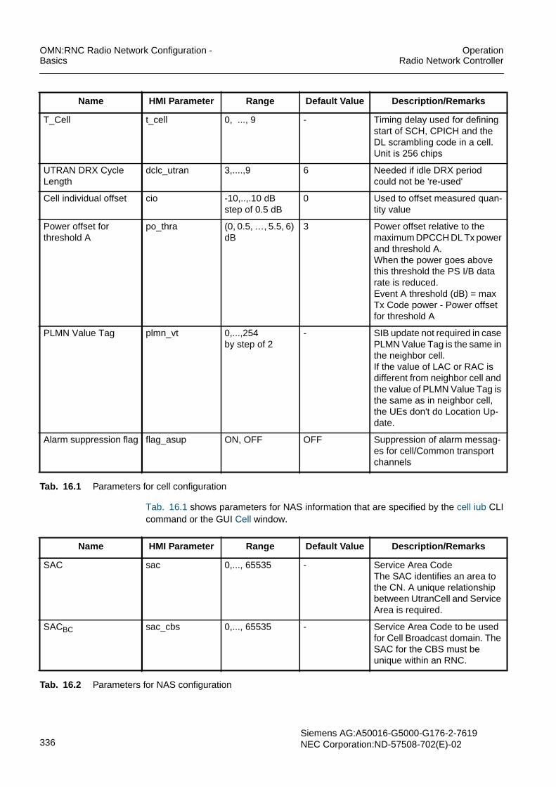
OMN:RNC Radio Network Configuration -Basics
OperationRadio Network Controller
336Siemens AG:A50016-G5000-G176-2-7619NEC Corporation:ND-57508-702(E)-02
Tab. 16.1 shows parameters for NAS information that are specified by the cell iub CLIcommand or the GUI Cell window.
T_Cell t_cell 0, ..., 9 - Timing delay used for definingstart of SCH, CPICH and theDL scrambling code in a cell.Unit is 256 chips
UTRAN DRX CycleLength
dclc_utran 3,....,9 6 Needed if idle DRX periodcould not be 're-used'
Cell individual offset cio -10,..,.10 dBstep of 0.5 dB
0 Used to offset measured quan-tity value
Power offset forthreshold A
po_thra (0, 0.5, …, 5.5, 6)dB
3 Power offset relative to themaximum DPCCH DL Tx powerand threshold A.When the power goes abovethis threshold the PS I/B datarate is reduced.Event A threshold (dB) = maxTx Code power - Power offsetfor threshold A
PLMN Value Tag plmn_vt 0,...,254by step of 2
- SIB update not required in casePLMN Value Tag is the same inthe neighbor cell.If the value of LAC or RAC isdifferent from neighbor cell andthe value of PLMN Value Tag isthe same as in neighbor cell,the UEs don't do Location Up-date.
Alarm suppression flag flag_asup ON, OFF OFF Suppression of alarm messag-es for cell/Common transportchannels
Name HMI Parameter Range Default Value Description/Remarks
Tab. 16.1 Parameters for cell configuration
Name HMI Parameter Range Default Value Description/Remarks
SAC sac 0,..., 65535 - Service Area CodeThe SAC identifies an area tothe CN. A unique relationshipbetween UtranCell and ServiceArea is required.
SACBC sac_cbs 0,..., 65535 - Service Area Code to be usedfor Cell Broadcast domain. TheSAC for the CBS must beunique within an RNC.
Tab. 16.2 Parameters for NAS configuration

OperationRadio Network Controller
OMN:RNC Radio Network Configuration -Basics
Siemens AG: A50016-G5000-G176-2-7619NEC Corporation: ND-57508-702(E)-02 337
Tab. 16.3 shows timers that are specified by the cell iub CLI command or the GUI Cellwindow.
LAC lac 1,.., 65533,65535
- Location Area CodeRNC can use 16 different LACvalues
RAC rac 0,..., 255 - Routing Area Code
Network OperatorMode
nwom Mode1, Mode2 - Network operation mode isused to indicate whether the Gsinterface is installed or not.When Gs interface is present,UE can initiate combined pro-ceduresMode 1: Gs interface is present;combined procedure by UEMode 2: Gs interface is notpresent; no combined proce-dures by UE
Attach-Detach atdt Attach/ detachnot allowed,attach/ detachmandatory
- This parameter indicateswhether the attach and detachprocedure are required to beused or not whenever it isswitched on or off.
CS periodic updatetimer
tmr_cspu 0, ...,1530 minby step 6 min
30 T3212Value 0 mean infiniteControls the periodic update(Location Update Request) ofthe availability of the UE to thenetwork, i.e. UEs shall not per-form periodic location update.
Name HMI Parameter Range Default Value Description/Remarks
Tab. 16.2 Parameters for NAS configuration
Name HMI Parameter Range Default Value Description/Remarks
T300 t300 100, 200... 2000by step of 200,3000, 4000,6000, 8000 ms
1000 ms Timer started in UE at transmis-sion of RRC CONNECTIONREQ and stopped after the re-ception of RRC CONNECTIONSETUP
N300 n300 0,....,7 3 Max. Number of repetitions ofRRC CONNECTION REQ
T302 t302 100, 200... 2000by step of 200,3000, 4000,6000, 8000 ms
4000 ms This parameter indicates thenumber of allowed retransmis-sions of a CELL UPDATEmessage.
Tab. 16.3 Timers

OMN:RNC Radio Network Configuration -Basics
OperationRadio Network Controller
338Siemens AG:A50016-G5000-G176-2-7619NEC Corporation:ND-57508-702(E)-02
N302 n302 0,....,7 3 Number of allowed retransmis-sions of a CELL UPDATEREQUEST message
T304 t304 100, 200, 400,1000, 2000 ms
1000 ms This is a timer for the UE. Itstarts upon transmission of theUE CAPABILITY INFORMA-TION message and stops uponreception of the UE CAPABILI-TY INFORMATION CONFIRMmessage.
N304 n304 0,....,7 1 This parameter indicates themaximum number of retrans-missions of the UE CAPABILI-TY INFORMATION message.
T305(Periodical cell updateTimer)
tpcu 0, 5, 10, 30, 60,120, 360, 720min
30 min Define the time period betweenupdating a CELL or an URAValue ‚0' means ‚no update'
T307 t307 5, 10, 15, 20, 30,40, 50 s
30 s Started when the T305 timerhas expired and the UE detects“out of service area” andstopped when the UE detects“in service area”. Determinesthe time a UE is allowed tosearch for a suitable cell while aCell Update is pending.
T308 t308 40, 80, 160, 320ms
320 ms This is a timer for the UE. Itstarts upon transmission of theRRC CONNECTION RE-LEASE COMPLETE message.
T309 t309 1,..., 8 s 5 s Started upon reselection of acell belonging to another radioaccess system from connectedmode. Stopped after successfulestablishment of a connectionin the new cell.
T312 t312 1,....,15 s 1 s Timer started in UE on estab-lishment of dedicated channel.Timer stopped in UE, if N312consecutive 'IN_SYNC_IND'have been received from theUE.
N312 n312 1, 2, 4, 10, 20,50, 100, 200,400, 600, 800,1000
1 Number of consecutive'IN_SYNC_IND' necessary inorder to declare the successfulestablishment of a dedicatedchannel
Name HMI Parameter Range Default Value Description/Remarks
Tab. 16.3 Timers

OperationRadio Network Controller
OMN:RNC Radio Network Configuration -Basics
Siemens AG: A50016-G5000-G176-2-7619NEC Corporation: ND-57508-702(E)-02 339
T313 t313 0,...,15 s 3 Radio Link Timeout: T313starts if N313 consecutive"OUT_SYNC_IND" have beenreceived from a UE.Within T313 N315'IN_SYNC_IND' are expectedto be received within the UE.Otherwise a Radio Link Failureis to be detected
N313 n313 1, 2, 4, 10, 20,50, 100, 200
20 Number of'OUT_OF_SYNC_IND' thattrigger start of T313.
T314 t314 0, 2, 4, 6, 8, 12,16, 20 s
12 s Started when the criteria for ra-dio link failure are fulfilled andstopped when the Cell Updateprocedure has been complet-ed.
T315 t315 0,10, 30, 60, 180,600, 1200,1800s
180 Started when the criteria for ra-dio link failure are fulfilled andstopped when the Cell Updateprocedure has been completed
N315 n315 1, 2, 4, 10, 20,50, 100, 200,400, 600, 800,1000
1 Number of successive'IN_SYNC_IND' to be receivedduring T313.
T316 t316 0, 10, 20, 30, 40,50 s, infinity
30 s Started when the UE detects“out of service area” inURA_PCH or Cell_PCH state,stopped when the UE detects“in service area”.
T317 t317 0,10, 30, 60, 180,600, 1200, 1800s
180 s Started when the T316 expiresand the UE detects “out of ser-vice area”, stopped when theUE detects “in service area”.
Name HMI Parameter Range Default Value Description/Remarks
Tab. 16.3 Timers

OMN:RNC Radio Network Configuration -Basics
OperationRadio Network Controller
340Siemens AG:A50016-G5000-G176-2-7619NEC Corporation:ND-57508-702(E)-02
16.1.1 Adjacent UTRAN CellsTab. 16.4 shows parameters for adjacent UTRAN cells that are specified by the cell aciCLI command or the GUI Cell window.
Name HMI Parameter Range Default Value Description/Remarks
Cell ID cellid 0,..., 65535 - Identifies an UTRAN Cell in aRNC
Node B ID nodebid 0,...,1023 - Identifies a Node B within thescope of the RNC
MCC mcc 3 digits 0-9 - Mobile Country Code
MNC mnc 2-3 digits 0-9 - Mobile Network Code;MCC+MNC uniquely identify aPLMNNote: It is assumed thatMCC+NCC is identical for CSand PS for each given cell.
UTRAN cell ID(RNC ID + Cell ID)
cellid_u 0, ..., 4095;0,..., 65535
- Identifies an UTRAN celluniquely in a UTRAN
Adjacent Cell Informa-tion Indicator
acii Handover,Selection andRe-selection,All
All This parameter indicates forwhich purpose the adjacent cellinformation is used.
Same Antenna same_ant False, True False True: The adjacent cell is at-tached to the same antennaand has, therefore, the samecoverage.In case of Intra-fre-quency, this attribute cannot bespecified.In case of Inter-fre-quency, this parameter is indis-pensable. 'True' can only be setif AdjacentUtranCell is withinthe same Node B.
Cell individual offset cio -10,..,.10 dBstep of 0.5 dB
0 Used to offset measured quan-tity value
Qoffset1 (s,n) qoffset1 -50,...,50 dB 0 This specifies the offset be-tween the two cells in case thequality measure for cell selec-tion and re-selection is set toCPICH RSCP.
Qoffset2 (s,n) qoffset2 -50,...,50 dB 0 This specifies the offset be-tween the two cells. It is usedfor FDD cells in case the qualitymeasure for cell selection andre-selection is set to CPICHEc/N0.
Tab. 16.4 Parameters for adjacent UTRAN cells

OperationRadio Network Controller
OMN:RNC Radio Network Configuration -Basics
Siemens AG: A50016-G5000-G176-2-7619NEC Corporation: ND-57508-702(E)-02 341
16.1.2 External UTRAN CellsTab. 16.1 shows parameters for external UTRAN cells that are specified by the euc CLIcommand or via the GUI External UMTS Cell window. Tab. 16.40 provides informationon optional parameters for external GSM cells that are specified by the euc hcs CLI com-mand or via the GUI External UMTS Cell window.
Name HMI Parameter Range Default Value Description/Remarks
RNC ID rncid 0,..., 4095 Identifies a RNC in a PLMN
C-ID cellid 0,..., 65535 Identifies an UTRAN Cell in aRNC
MCC mcc 3 digits 0-9 Mobile Country Code
MNC mnc 2-3 digits 0-9 Mobile Network Code;MCC+MNC uniquely identify aPLMNNote: It is assumed thatMCC+NCC is identical for CSand PS for each given cell
LAC lac 1,.., 65533,65535
Location Area Code
RAC rac 0,...,255 Routing Area Code
Primary CPICH scram-bling code
sc_pcpi 0,...,511 The DL scrambling code of theCPICH identifies a cell uniquelyif the code is always allocatedwith sufficient reuse distances.On modification the duplicationof the P-CPICH scramblingcode is prohibited
Primary CPICH Txpower
pwr_pcpit -10,...,50 dBm 33 dBm Indicates the total transmittedpower of the CPICH (this infor-mation is needed, if the UE isrequired to measure the DLpathloss)
UARFCN Uplink uarfcn Uplink:12, 37, 62, 87,112, 137, 162,187, 212, 237,262, 287,9262,… , 9538,9612,..., 9888Downlink:412, 437, 462,487, 512, 537,562, 587, 612,637, 662, 687,9662, …, 9938,10562,..., 10838
UTRA Absolute Radio Fre-quency Channel Number. Achannel number correspondsto 5 MHz bandwidth. Its locationin the frequency band is definedwith a granularity of 200 KHz.
Tab. 16.5 Parameters for cell configuration

OMN:RNC Radio Network Configuration -Basics
OperationRadio Network Controller
342Siemens AG:A50016-G5000-G176-2-7619NEC Corporation:ND-57508-702(E)-02
16.1.3 Adjacent GSM CellsTab. 16.1 shows parameters for adjacent GSM cells that are specified by the cell agciCLI command or the GUI Cell window.
Maximum Allowed ULTx Power
maut -50,...,33 dBm 24 dBm Specifies the maximum alloweduplink transmission power inthe cell.
Qqualm qqualm -24,...,0 dBm - 20 dBm The minimum required qualitylevel (Ec/N0) in the neighborcell.
Qrxlevmin qrxlevmin -115,...,-25 dBmstep of 2 dBm
-101 dBm Specifies the minimum requiredRX level in the neighbor cell
Name HMI Parameter Range Default Value Description/Remarks
Tab. 16.5 Parameters for cell configuration
Name HMI Parameter Range Default Value Description/Remarks
Cell ID cellid 0,..., 65535 - Identifies an UTRAN Cell in aRNC
Node B ID nodebid 0,...,1023 - Identifies a Node B within thescope of the RNC
External GSM identifi-er
egcid 0,...,65535 - Identifies unambiguously therelationship between a UTRANcell and a GSM cell
Adjacent Cell Informa-tion Indicator
acii Handover,Selection andRe-selection,Both
Both This parameter indicates forwhich purpose the adjacent cellinformation is used.
Qoffset1s,n qoffset1 -50,...,50 dB 0 This specifies the offset be-tween the two cells if the qualitymeasure for cell selection andre-selection is set to CPICHRSCP.In dB
Cell individual offset cio -50,..,.50 dB 0 Used to offset measured quan-tity value
Tab. 16.6 Parameters for adjacent GSM cells

OperationRadio Network Controller
OMN:RNC Radio Network Configuration -Basics
Siemens AG: A50016-G5000-G176-2-7619NEC Corporation: ND-57508-702(E)-02 343
16.1.4 External GSM Cell InformationTab. 16.1 shows parameters for external GSM cells that are specified by the egc CLIcommand or via the GUI External GSM Cell window. Tab. 16.41 provides informationon optional parameters for external GSM cells that are specified by the egc hcs CLI com-mand or via the GUI External GSM Cell window.
Name HMI Parameter Range Default Value Description/Remarks
External GSM identifi-er
egcid 0,...,65535 - Identifies unambiguously therelationship between a UTRANcell and a GSM cell
MCC mcc 3 digits 0-9 - Mobile Country Code
MNC mnc 2-3 digits0-9 - Mobile Network Code.MCC+MNC uniquely identify aPLMN
(GSM)-Cell ID cellid_g 0,...,65535 - The MCC+MNC+LAC+Cell IDcomprise the Cell Global Identi-ty which is used by the CN foridentifying the correspondingBSC
LAC lac_g 1, .. ,65533,65535
- Location Area Code
Band Indicator bandi DCS 1800 bandused,PCS 1900 bandused
- Indicates how to interpret theBCCH ARFCN
ARFCN arfcn 0,...,1023 - Absolute Radio FrequencyNumber of the GSM cell
NCC ncc 0,...,7 - ARFCN+NCC+BCC identifiesthe cell on radio interface
BCC bcc 0,...,7 - ARFCN+NCC+BCC identifiesthe cell on radio interface
Maximum allowed ULTX power
maut -50,...,33 dBm 33 dBm Equals MS_TX_POWER_MAX
Qrxlevmin qrxlevmin -115,...,-25 dBmby step of 2 dBm
- 101 dBm Specifies the minimal requiredRX level in the cell
Tab. 16.7 Parameters for external GSM cells

OMN:RNC Radio Network Configuration -Basics
OperationRadio Network Controller
344Siemens AG:A50016-G5000-G176-2-7619NEC Corporation:ND-57508-702(E)-02
Network Control Mode mode_nc 0,...,3 0 Controls the UE measurementbehavior to be applied initially intarget GPRS cell:Value ‚0': The UE has to per-form normal UE controlled cellselection/re-selection proce-dure when camping on the tar-get cell.Value ‚1' and ‚2': The UE has toreport measurements on adja-cent cells, so that the 2G net-work could order cellreselection.Value ‚3': The UE has to readthe value for NC mode from 2Gsystem information first.
HCS_PRIO pri_hcs 0,..., 7 0 This specifies the HCS prioritylevel
QHCS qhcs 0,...., 99 0 Specifies the quality thresholdlevels for applying prioritized hi-erarchical cell re-selection.Value 0 means not used
Penalty_time tmpnlt 0, 10, 20, 30, 40,50, 60 s
0 Specifies the time duration forwhich the Temporary_Offsetis applied for the cell.Value 0 means not used
Temporary_ offset1 offset1_temp 3, 6, 9, 12, 15,18, 21, inf dB
6 dB Specifies the offset applied tothe H and R criteria for the cellfor the duration ofPenalty_Time.It is used forGSM cells in case the qualitymeasure is set to CPICH RSCP
Name HMI Parameter Range Default Value Description/Remarks
Tab. 16.7 Parameters for external GSM cells

OperationRadio Network Controller
OMN:RNC Radio Network Configuration -Basics
Siemens AG: A50016-G5000-G176-2-7619NEC Corporation: ND-57508-702(E)-02 345
16.1.5 Geographical Coordinates of a CellTab. 16.1 shows parameters for the geographical coordinates of a cell that are specifiedby the cell gc CLI command or the GUI Cell window.
Name HMI Parameter Range Default Value Description/Remarks
Cell ID cellid 0,..., 65535 - Identifies an UTRAN Cell in aRNC
Node B ID nodebid 0,...,1023 - Identifies a Node B within thescope of the RNC
UTRAN Access Point Position (1 Set of Geographical Coordinates for geographical position of the Node B an-tenna)
Latitude Sign gc_uapp North, South - Indicates the northern or south-ern hemisphere
Degrees of Latitude gc_uapp 0,..., 8388607 - The IE value (N) is derived bythis formula:N < X * 223/90 < N+1X being the latitude in degree(0˚.. 90˚)
Degrees of Longitude gc_uapp -8388608,..,8388607
- The IE value (N) is derived bythis formula:N < X * 224/360 < N+1X being the longitude in degree(-180˚..+180˚)
Geographical Area (3 up to 15 Sets of Geographical Coordinates)
Latitude Sign gc_cpd North, South - Indicates the northern or south-ern hemisphere
Degrees of Latitude gc_cpd 0,..., 8388607 - The IE value (N) is derived bythis formula:N < X * 223/90 < N+1X being the latitude in degree(0˚.. 90˚)
Degrees of Longitude gc_cpd -8388608,..,8388607
- The IE value (N) is derived bythis formula:N < X * 224/360 < N+1X being the longitude in degree(-180˚..+180˚)
Tab. 16.8 Parameters for the geographical coordinates of cell

OMN:RNC Radio Network Configuration -Basics
OperationRadio Network Controller
346Siemens AG:A50016-G5000-G176-2-7619NEC Corporation:ND-57508-702(E)-02
16.1.6 Common Channel Related InformationTab. 16.9 shows parameters for downlink common channel control that are specified bythedlcc CLI command and the GUI Downlink Common Channel window
Name HMI Parameter Range Default Value Description/Remarks
Cell identifier cellid 0,..., 65535 - Identifies an UTRAN Cell in aRNC
Node B ID nodebid 0,...,1023 - Identifies a Node B within thescope of the RNC
Common channelgroup ID
id_cch fixed to 0 This parameter indicates acommon channel groupuniquely within uplink commonchannels.
Common channel ob-ject type
ccho_type 0,...,2 This parameter indicates whichtransport channel is carried.
CTCH supported fach_ctch True, false False Indicates whether Cell Broad-cast Channel is supported inthe cell
Multiple TTI MTTI no_rfrm 1, ..., 255 1 Period of frames that carryCTCH information (1 meanseach frame).The value of N defines the max-imum data rate of the CTCH
CTCH Allocation Peri-od (N)
peri_rfrm 1, ..., 256 10 Period of frames that carryCTCH information (1 meanseach frame).The value of N defines the max-imum data rate of the CTCH
Cell Broadcast ServiceFrame Offset (K)
frmofs_cbs 0, ..., 255 0 The parameter specifies K. Kmeans CBS frame offset, inte-ger number of radio frames.0 < K < N - 1, where K is a mul-tiple of MTTIThis parameter is multiple ofMTTI.
Max FACH power mfachp -35,...,15 dBby step of 0.1 dB
- 3, - 3 Indicates the difference of theFACH power to the PrimaryCPICH Tx power.Second parameter is for MaxFACH power of DTCH
PCH power offset po_pch -35,...,15 dBby step of 0.1 dB
- 3 Indicates the difference of thePCH power to the PrimaryCPICH Tx power
PICH power offset po_pich -10,..., 5 dB - 6 Indicates the difference of thePICH power to the PrimaryCPICH Tx power
Tab. 16.9 Parameters for DL common channel control

OperationRadio Network Controller
OMN:RNC Radio Network Configuration -Basics
Siemens AG: A50016-G5000-G176-2-7619NEC Corporation: ND-57508-702(E)-02 347
Tab. 16.10 shows parameters for cell configuration that are specified by the ulcc CLIcommand and the GUI Uplink Common Channel window.
DL scrambling code forS-CCPCH
sccpch_scd 0,…, 15 0 = Primary scrambling code ofthe cell1,..,15 = Secondary scramblingcodeOnly 0 allowed according TS25.213
S-CCPCH offset sccpchoff 0, ..., 38144 chipby step of 256
0 Delay of the SecondaryCCPCH relative to the PrimaryCCPCH
DL channelizationcode number for S-CCPCH
sccpch_ccd 0, ..., 255 1 4 for S-CPCH(PCH),1 for S-CPCH(FACH) and S-CPCH(PCH/FACH combine)
DL channelizationcode number for PICH
pich_ccd 0, ..., 255 3 This parameter can be speci-fied only when ccho_type=0 or2 is specified.
Name HMI Parameter Range Default Value Description/Remarks
Tab. 16.9 Parameters for DL common channel control
Name HMI Parameter Range Default Value Description/Remarks
Cell identifier cellid 0,..., 65535 - Identifies an UTRAN Cell in aRNC
Node B ID nodebid 0,...,1023 - Identifies a Node B within thescope of the RNC
Common channelgroup ID
id_cch fixed to 0 This parameter indicates acommon channel groupuniquely within uplink commonchannels.
Scrambling CodeNumber
sc_wno 0,...,15 - Network planning parameter,which should be different in ad-jacent cells.
Available Signatures avsgn 0,...,15 1 List of permitted signatures foraccess on the RACH.The same value cannot be as-signed.
AICH power offset po_aich -22,...,5 dB -6 Indicates the difference of theAICH power to the PrimaryCPICH Tx power.
Constant value constval -35,...,-10 dB -20
Sub channel No. subch 0,...,11 0,1,2,3,4,5,6,7,8,9,10,11
List of permitted sub-channels.
Tab. 16.10 Parameters for UL common channel control

OMN:RNC Radio Network Configuration -Basics
OperationRadio Network Controller
348Siemens AG:A50016-G5000-G176-2-7619NEC Corporation:ND-57508-702(E)-02
AICH transmissionTiming
aicht 0, 1 1 See 3GPP TS25.211
DL channelizationcode number for AICH
aich_ccd 0,...,255 2 Indicates the DL Channeliza-tion Code number for a AICH(see TS25.213).
Preamble threshold prmthr -36.0,..., 0.0 dBby step of 0.5 dB
-18.0
Power ramp step pwrs 1,...,8 2 Power step when no acquisitionindicator is received
Preamble retrans max prmretmax 1,...,64 64 Maximum number of pream-bles in one preamble rampingcycle
Maximum number ofpreamble cycles
mmax 1,...,32 32 Maximum number of preamblecycles
NB01min nb01min 0,...,50 0 Sets lower bound for randomback-off
NB01max nb01max 0,...,50 5 Sets upper bound for randomback-off
Available SignatureStart Index
avestr 0,...,15 0,0,0,0,0,0,0 If number of parameters issmaller than maximum the restof parameters make up default
Available SignatureEnd Index
aveend 0,...,15 7 * (Number ofavsgn-1)
If number of parameters issmaller than maximum the restof parameters make up default
Assigned Sub ChannelNumber
sbch_asn 0,...,15 1111, 1111,1111, 1111,1111, 1111,1111
If number of parameters issmaller than maximum the restof parameters make up default
Persistence scalingfactor
factor 0.2,...,0.9by step of 0.1
0.9, 0.9, 0.9,0.9, 0.8
Scaling factorsIf number of parameters issmaller than maximum the restof parameters make up default
Ac to ASC mapping ta-ble
map_tbl 0,...,7 6,5,4,3,2,1,0 If number of parameters issmaller than maximum the restof parameters make up default
Name HMI Parameter Range Default Value Description/Remarks
Tab. 16.10 Parameters for UL common channel control

OperationRadio Network Controller
OMN:RNC Radio Network Configuration -Basics
Siemens AG: A50016-G5000-G176-2-7619NEC Corporation: ND-57508-702(E)-02 349
16.2 Parameters for Radio Resource ManagementThe following tables list the parameters for radio resource management that areconfigurable by the operator.
16.2.1 Parameters for Radio Bearer TranslationTab. 16.11 shows parameter for radio bearer translation that are specified by the rbcCLI command or the GUI Radio Bearer Control. For more information see Radio BearerTranslation.
Name HMI Parameter Range Default Value Description/Remarks
Standalone SRB rate srbr (3.4, 13.6) kbit/s 3.4 kbit/s Rate of standalone DCCH
Tab. 16.11 Parameters for radio bearer translation

OMN:RNC Radio Network Configuration -Basics
OperationRadio Network Controller
350Siemens AG:A50016-G5000-G176-2-7619NEC Corporation:ND-57508-702(E)-02
16.2.2 Parameters for Radio Bearer ControlTab. 16.15 shows mandatory parameters for radio bearer control that are specified bythe rbc CLI command or the GUI Radio Bearer Control. For more information see RadioBearer Control.
Name HMI Parameter Range Default Value Description/Remarks
Timer for the switchfrom Cell_FACH toCell_PCH mode
tfach_pchr 0,...,65535 s 300 s Timer for the switch fromCell_FACH to Cell_PCH mode
Timer for the switchfrom Cell_PCH to Idlemode
tpch_idler 0,...,65535 s 7200 s Timer for the switch fromCell_PCH to Idle mode orURA_PCH to Idle
Max_C_Crossing max_ccros 0,...,65535 20 Maximum number of cellcrossing in Cell_PCH modebefore switch to URA_PCHmodeValue of '0' indicates that thereis no URA_PCH state
DCH INACTIVE state dch_inact Allowed, Not allowed Allowed Allowed: Inactive Interac-tive/background PS RABs onmulticall are reconfigured toUL:0 DL: 0 kbit/s.Not allowed: Inactive PS RABson multicall are not reconfig-ured to UL:0 DL: 0 kbit/s.
Channel for non RABrelated RRC Connec-tions
ch_nonrab Common, Dedicated Dedicated Indicates channel type for RRCConnection establishmentwhen establishment cause is:- Registration,- Detach,- Originating High Priority Sig-nalling,- Originating Low Priority Sig-nalling,- Terminating High Priority Sig-nalling,- Terminating Low Priority Sig-nalling.
Tab. 16.12 Radio bearer control parameters

OperationRadio Network Controller
OMN:RNC Radio Network Configuration -Basics
Siemens AG: A50016-G5000-G176-2-7619NEC Corporation: ND-57508-702(E)-02 351
Channel for interac-tive or backgroundclass RABs
ch_ibrab Common, Dedicated Dedicated Indicates channel type for RRCConnection when establish-ment cause is:- Originating Interactive Call,- Originating Background Call,- Terminating Interactive Call,- Terminating Background Call,Indicates channel type for RABestablishment when trafficclass is:- Interactive,- Background.
T_Streaming Inactivi-ty
t_strminact 0,1,..,65535 s 0 Timer to release inactive PSStreaming RABsThe value 0 means no releasedue to inactivity
Switching from DCH to FACH
Timer for the switchfrom DCH to FACH
tdch_fachr 0 ... 65535 s 2 s Period of uplink and downlinkinactivity before the PS I/BRAB is switched to FACH; 0means that inactivity is notmonitored and the connectionis not switched to FACH.
Switching from FACH to DCH
Timer for the switchfrom FACH to DCH
tfach_dchue 0, 10, 20, 40, 60, 80,100, 120, 160, 200,240, 320, 640, 1280,2560, 5000 ms
20 ms Time to trigger for switchingfrom FACH to DCH
Uplink upper trans-port channel trafficvolume threshold
ul_fdpt 8, 16, 32, 64, 128,256, 512, 1024, 2k,3k, 4k, 6k, 8k, 12k,16k, 24k, 32k, 48k,64k, 96k, 128k,192k, 256k, 384k,512k, 768k
1024 Uplink upper transport channeltraffic volume threshold
Downlink upper trans-port channel trafficvolume threshold
dl_upt 8, 16, 32, 64, 128,256, 512, 1024, 2k,3k, 4k, 6k, 8k, 12k,16k, 24k, 32k, 48k,64k, 96k, 128k,192k, 256k, 384k,512k, 768k
1024 Downlink upper transportchannel traffic volume thresh-old
Switching from HS-DSCH to FACH
Name HMI Parameter Range Default Value Description/Remarks
Tab. 16.12 Radio bearer control parameters

OMN:RNC Radio Network Configuration -Basics
OperationRadio Network Controller
352Siemens AG:A50016-G5000-G176-2-7619NEC Corporation:ND-57508-702(E)-02
16.2.2.1 Parameters for Radio Link Quality MeasurementsTab. 16.13 shows parameters related to Node B transmission code power dedicatedmeasurements. The parameters are specified by dmi CLI command with exception ofthe power offset for threshold A which is specified by the cell iub CLI command or theGUI Cell window. For more information see Bit Rate Adaptation.
Timer for the switchfrom HS-DSCH toFACH
thsdsch_fach 0 .. 65535 s 30 s Period of uplink and downlinkinactivity before the PS I/BRAB is switched from HS-DSCH to FACH. 0 means thatinactivity is not monitored andthe connection is not switchedto FACH.
Rate availability
Initial PS Interactiveor Background datarate
ini_pib 32/32, 64/64,64/128, 64/384 kbit/s
64/64 kbit/s Maximum initial bit rate to beassigned during PS I/B RABsetup
Name HMI Parameter Range Default Value Description/Remarks
Tab. 16.12 Radio bearer control parameters
Name HMI Parameter Range Default Value Description/Remarks
Event A configuration
Power offset forthreshold A(mandatory: per UT-RAN cell)
po_thra 0, 0.5, ..., 5.5,6 dB
3 dB The power offset parameter isrelative to the maximumDPCCH DL Tx power andthreshold A. When the powerexceeds this threshold, the PSI/B data rate is reduced.Event A threshold (dB)= maxTx Code Power - Power offsetfor threshold A
Power offset forthreshold A over Iur
po_thrai 0, 0.5, … ,5.5,6 dB
3 dB This parameter is used to de-fine threshold A on cells be-longing to the DRNC.
Measurementhysteresis Time
mmht_a 1... 6000,…Actual range:10 ms, 20 ms, …60000 ms
10 ms Node B BB card limitation;(N*100ms) rounded to thenearest 100 ms (is performedby the Node B)
Measurement filterCoefficient
mmfc_a 0, 1, 2, 3, 4, 5, 6,7, 8, 9, 11, 13,15, 17, 19, ...
0 Filter coefficient for layer 3 fil-tering
Event F configuration
Tab. 16.13 Node B transmission code power

OperationRadio Network Controller
OMN:RNC Radio Network Configuration -Basics
Siemens AG: A50016-G5000-G176-2-7619NEC Corporation: ND-57508-702(E)-02 353
16.2.2.2 Parameters for Traffic MeasurementsFor more information see Bit Rate Adaptation.
Buffer utilization measurements
Tab. 16.14 shows parameters for buffer utilization measurement that are specified bythe bumi CLI command or the GUI Buffer Utilization Measurement Information window.
Power offset forthreshold F (relative tothreshold A)
thrh_f 0, 0.5, … ,5.5,6 dB
3 dB The power offset parameter isrelative to the power thresholdA.Event F threshold (dB) = EventA threshold - Power offset forthreshold F.The default threshold shouldbe changed to 6 dB.
Power offset forthreshold F (relative tothreshold A) over Iur
thrh_fi 0, 0.5, … ,5.5,6 dB
3 dB This parameter is used to de-fine threshold F on cells be-longing to the DRNC.The default threshold shouldbe changed to 6 dB.
Measurementhysteresis time
mmht_f 1... 6000,…Actual range:10 ms, 20 ms, …60000 ms
10(100 ms)
Node B BB card limitation(N*100 ms) rounded to thenearest 100 ms (is performedby the Node B)
Measurement filtercoefficient
mmfc_f 0, 1, 2, 3, 4, 5, 6,7, 8, 9, 11, 13,15, 17, 19, ...
0 Filter coefficient for layer 3 fil-tering
Name HMI Parameter Range Default Value Description/Remarks
Tab. 16.13 Node B transmission code power
Name HMI Parameter Range Default Value Description/Remarks
Averaging period avgperi 500 ... 50000 msec 1000 msec Downlink averaging period
BRA rate decrease
Utilization thresholdfor BRA DL rate de-crease
uthr_decr 0 ... 100 %(in steps of 1averaging period)
20 % Describes the period of up-link and downlink inactivitybefore the PS I/B RAB isswitched to the FACH;0 means that inactivity is notmonitored and that the con-nection is not switched tothe FACH.
Tab. 16.14 Buffer utilization measurement parameters
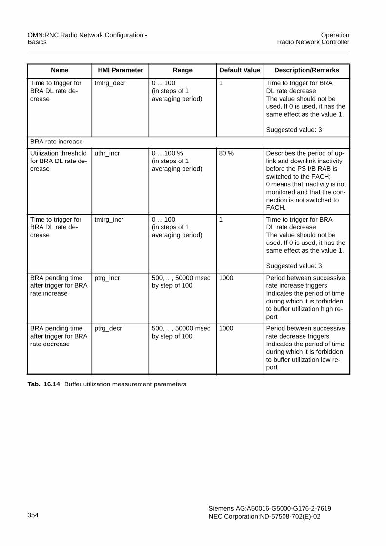
OMN:RNC Radio Network Configuration -Basics
OperationRadio Network Controller
354Siemens AG:A50016-G5000-G176-2-7619NEC Corporation:ND-57508-702(E)-02
Time to trigger forBRA DL rate de-crease
tmtrg_decr 0 ... 100(in steps of 1averaging period)
1 Time to trigger for BRADL rate decreaseThe value should not beused. If 0 is used, it has thesame effect as the value 1.
Suggested value: 3
BRA rate increase
Utilization thresholdfor BRA DL rate de-crease
uthr_incr 0 ... 100 %(in steps of 1averaging period)
80 % Describes the period of up-link and downlink inactivitybefore the PS I/B RAB isswitched to the FACH;0 means that inactivity is notmonitored and that the con-nection is not switched toFACH.
Time to trigger forBRA DL rate de-crease
tmtrg_incr 0 ... 100(in steps of 1averaging period)
1 Time to trigger for BRADL rate decreaseThe value should not beused. If 0 is used, it has thesame effect as the value 1.
Suggested value: 3
BRA pending timeafter trigger for BRArate increase
ptrg_incr 500, .. , 50000 msecby step of 100
1000 Period between successiverate increase triggersIndicates the period of timeduring which it is forbiddento buffer utilization high re-port
BRA pending timeafter trigger for BRArate decrease
ptrg_decr 500, .. , 50000 msecby step of 100
1000 Period between successiverate decrease triggersIndicates the period of timeduring which it is forbiddento buffer utilization low re-port
Name HMI Parameter Range Default Value Description/Remarks
Tab. 16.14 Buffer utilization measurement parameters

OperationRadio Network Controller
OMN:RNC Radio Network Configuration -Basics
Siemens AG: A50016-G5000-G176-2-7619NEC Corporation: ND-57508-702(E)-02 355
Traffic volume measurements
Tab. 16.15 shows traffic volume measurement parameters that are specified by the rbcCLI command or the GUI Radio Bearer Control.
16.2.2.3 Parameters for Call TracingTab. 16.16 shows parameters for call tracing that are specified by the dmi CLI com-mand.
Name HMI Parameter Range Default Value Description/Remarks
BRA rate decrease
Time to trigger forBRA UL rate de-crease
tbra_rdue 0, 10, 20, 40, 60, 80,100, 120, 160, 200,240, 320, 640, 1280,2560, 5000 (ms)
1280 ms Time to trigger for BRA UL ratedecrease
Suggested value: 2560 ms
RLC buffer thresh-old for BRA UL ratedecrease
ulbra_rdpt 8, 16, 32, 64, 128,256, 512, 1024, 2k,3k, 4k, 6k, 8k, 12k,16k, 24k, 32k, 48k,64k, 96k, 128k,192k, 256k, 384k,512k, 768k (bytes)
8k bytes RLC buffer threshold for BRAUL rate decrease
Suggested value: 128 bytes
BRA rate increase
Time to trigger forBRA UL rate in-crease
tbra_riue 0, 10, 20, 40, 60, 80,100, 120, 160, 200,240, 320, 640, 1280,2560, 5000 (ms)
1280 ms Time to trigger for BRA UL rateincrease
RLC buffer thresh-old for BRA UL rateincrease
ulbra_ript 8, 16, 32, 64, 128,256, 512, 1024, 2k,3k, 4k, 6k, 8k, 12k,16k, 24k, 32k, 48k,64k, 96k, 128k,192k, 256k, 384k,512k, 768k (bytes)
64k bytes RLC buffer threshold for BRAUL rate increase
Suggested values:4 k bytes
Tab. 16.15 Traffic volume measurement parameters
Name HMI Parameter Range Default Value Description/Remarks
call_trace_period peri_ct (10ms…1min)by step of 10ms(1min…1hr,…)by step of 1min
10 sec Determines the period for thededicated measurement forCall Trace
Measurement FilterCoefficient for SIR
mmfc_sir (0, 1, 2, 3, 4, 5, 6,7, 8, 9, 11, 13,15, 17, 19)
0 Filter coefficient for call tracemeasurements for SIR
Tab. 16.16 Parameters for call tracing

OMN:RNC Radio Network Configuration -Basics
OperationRadio Network Controller
356Siemens AG:A50016-G5000-G176-2-7619NEC Corporation:ND-57508-702(E)-02
16.2.3 Parameters for Pre-EmptionTab. 16.17 shows parameters for pre-emption that are specified by the rbc CLI com-mand or the GUI Radio Bearer Control.
16.2.4 Parameters for Higher Layer FilteringFor more information see Higher Layer Filtering.
16.2.4.1 Admission ControlTab. 16.18 shows mandatory parameters per UTRAN cell instance that are specified bythe cell adc CLI command or the GUI Cell window.
Measurement FilterCoefficient for SIR er-ror
mmfc_sirerr (0, 1, 2, 3, 4, 5, 6,7, 8, 9, 11, 13,15, 17, 19)
0 Filter coefficient for call tracemeasurements for SIR error
Measurement FilterCoefficient for Trans-mitted Code Power
mmfc_tcdp (0, 1, 2, 3, 4, 5, 6,7, 8, 9, 11, 13,15, 17, 19)
0 Filter coefficient for call tracemeasurements for TransmittedCode Power
Name HMI Parameter Range Default Value Description/Remarks
Tab. 16.16 Parameters for call tracing
Name HMI Parameter Range DefaultValue
Description/Remarks
Pre-emption flag flag_preempt False, True False The parameter is used to switch the fea-ture ON (“True”) and OFF (“False”) forthe following two purposes:- During the upgrade phase- If the operator wants to switch off thefeature
although the feature has been pur-chased.
Note:The same value should be used withinthe whole network.
Tab. 16.17 Pre-emption parameters
Name HMI Parameter Range Default Value Description/Remarks
Measurement filtercoefficient for RTWP
mmfc_rtpw (0, 1, 2, 3, 4, 5, 6, 7,8, 9, 11, 13, 15, 17,19)
0 Filter coefficient forRTWP measurements
Measurement filtercoefficient for trans-mitted carrier power
mmfc_tcrp (0, 1, 2, 3, 4, 5, 6, 7,8, 9, 11, 13, 15, 17,19)
0 Filter coefficient fortransmitted carrier pow-er measurements
Tab. 16.18 Parameters for admission control needed for higher layer filtering

OperationRadio Network Controller
OMN:RNC Radio Network Configuration -Basics
Siemens AG: A50016-G5000-G176-2-7619NEC Corporation: ND-57508-702(E)-02 357
16.2.4.2 Congestion ControlTab. 16.19 shows mandatory parameters per UTRAN cell instance that are specified bythe cell cctl CLI command or in the Cell GUI window.
16.2.4.3 Outer Loop Power ControlTab. 16.20 shows mandatory parameters per RNC instance that are specified by theolpc CLI command or the GUI Outer Loop Power Control window.
16.2.4.4 Dedicated Measurement InformationTab. 16.21 and Tab. 16.22 show mandatory parameters per RNC instance for trans-mission code power dedicated measurements that are specified by the dmi CLI com-mand.
Name HMI Parameter Range Default Value Description/Remarks
Measurement filtercoefficient for RTWP
mmfc_rtpw (0, 1, 2, 3, 4, 5, 6, 7,8, 9, 11, 13, 15, 17,19)
0 Filter coefficient for re-ceived total wide bandpower event triggeredmeasurements.
Measurement filtercoefficient for trans-mitted carrier power
mmfc_tcrp (0, 1, 2, 3, 4, 5, 6, 7,8, 9, 11, 13, 15, 17,19)
0 Filter coefficient fortransmitted carrier pow-er event triggered mea-surements.
Tab. 16.19 Parameters for congestion control needed for higher layer filtering
Name HMI Parameter Range Default Value Description/Remarks
Measurement filtercoefficient for SIRerror
mmfc_sierr (0, 1, 2, 3, 4, 5, 6, 7,8, 9, 11, 13, 15, 17,19)
0 Filter coefficient for fil-tering of SIR Error mea-surements for Events Eand F
Tab. 16.20 Parameters for outer loop power control needed for higher layer filtering
Name HMI Parameter Range Default Value Description/Remarks
Measurement filtercoefficient
mmfc_a (0, 1, 2, 3, 4, 5, 6, 7,8, 9, 11, 13, 15, 17,19)
0 Filter coefficient for layer 3 fil-tering
Tab. 16.21 Dedicated measurement information for event A
Name HMI Parameter Range Default Value Description/Remarks
Measurement filtercoefficient
mmfc_f (0, 1, 2, 3, 4, 5, 6, 7,8, 9, 11, 13, 15, 17,19)
0 Filter coefficient for layer 3 fil-tering
Tab. 16.22 Dedicated measurement information for event F

OMN:RNC Radio Network Configuration -Basics
OperationRadio Network Controller
358Siemens AG:A50016-G5000-G176-2-7619NEC Corporation:ND-57508-702(E)-02
16.2.5 Parameters for Power ControlFor more information see Power Control.
16.2.5.1 Parameters for Uplink Outer Loop Power ControlTab. 16.23 shows parameters for uplink outer loop power control that are specified bythe olpc CLI command or the GUI Outer Loop Power Control window. For moreinformation see Outer Loop Power Control (OLPC).
Tab. 16.24 shows measurement filter coefficient parameters for uplink outer loop powercontrol that are specified by the olpc CLI command or the GUI Outer Loop Power Controlwindow.
Name HMI Parameter Range Default Value Description/Remarks
Step size step_size 0, ..., 25.5 dBin step of 0.1
0.3 dB Step size of the outer loop powercontrol.
Update threshold thr_upd 0, ..., 25.5 dBin step of 0.1
0.1 dB Threshold value for new update
SIRerror,min lowthr_sirerr -31,...,31 dBin step of 0.5
- 3 dB Lower threshold of SIR errorNote: If the difference withSIRerror,max is within 1.0 dB, ULOLPC may not work correctly.
SIRerror,max upthr_sirerr -31,...,31 dBin step of 0.5
3 dB Upper threshold of SIR errorNote: If the difference withSIRerror,min is within 1.0 dB, ULOLPC may not work correctly.
Tab. 16.23 Parameters for outer loop power control
Name HMI Parameter Range Default Value Description/Remarks
Measurement filtercoefficient for SIRer-ror
mmfc_sierr (0, 1, 2, 3, 4, 5, 6, 7,8, 9, 11, 13, 15, 17,19)
0 Filter coefficient for filteringof SIR error measurementsfor events E and F
Tab. 16.24 Measurement filter coefficient parameter for outer loop power control

OperationRadio Network Controller
OMN:RNC Radio Network Configuration -Basics
Siemens AG: A50016-G5000-G176-2-7619NEC Corporation: ND-57508-702(E)-02 359
16.2.5.2 Parameters for Inner Loop Power ControlTab. 16.25 shows parameters for inner loop power control that are specified by the celliub CLI command or the GUI Cell window except the DL TPC pattern 01 count, which isspecified by the sccsr CLI command or the GUI Synchronization Configuration for CellSetup Request window. For more information see Inner Loop Power Control.
Name HMI Parameter Range Default Value Description/Remarks
Primary CPICH Txpower
pwr_pcpit -10,...,50 dB 33 dB Indicates the total transmittedpower of the CPICH power.(This information is needed if theUE is required to measure theDL pathloss).
BCH power offset po_bch -35,...,10 dB - 3 dB Indicates the difference betweenthe BCH power and the primaryCPICH Tx power.
Primary SCH poweroffset
po_psch -35,...,10 dB - 3 dB Indicates the difference betweenthe primary SCH power and theprimary CPICH Tx power.
Secondary SCHpower offset
po_ssch -35,...,10 dB - 3 dB Indicates the difference betweenthe secondary SCH power andthe primary CPICH Tx power.
Maximum DLtransmission power
max_dltp 0, 1, 2, ..., 50 dB 43 dB Maximum power for all downlinkchannels added together, that isallowed to be used in a cell.
Poffset poffset -50,...,50 dB 16 dB Power offset for evaluation ofmax. Transmission power
Max power value pwval_max -35,...,15 dB 6 dB Cell specific max DL transmis-sion power (relative to CPICHpower).
DL TPC pattern 01count
dltpc01 0,...,30 8 The DL TPC pattern 01 count IEin the NBAP:CELL SETUP RE-QUEST message contains thevalue of the parameter n whichis used to determine the DL TPCpattern on radio links markedwith “first LS” by the “First RLSindicator” IE before UL synchro-nization is achieved.
Tab. 16.25 Parameters for power control initialization

OMN:RNC Radio Network Configuration -Basics
OperationRadio Network Controller
360Siemens AG:A50016-G5000-G176-2-7619NEC Corporation:ND-57508-702(E)-02
16.2.5.3 Parameters for Power BalancingTab. 16.26 shows the parameter for downlink power balancing that are specified by thedlpb CLI command or the GUI Downlink Power Balancing Information window. For moreinformation see Power Balancing.
Name HMI Parameter Range Default Value Description/Remarks
DL PB system upgradeflag
flag_pb TRUE,FALSE
FALSE TRUE: DL power balancing isactivated.FALSE: DL power balancing isdeactivated.
Adjustment period, k adj_prd 1 … 256frames
1 frame Indicates the frequency of poweradjustments.
Adjustment ratio, r adj_rto 0 …. 100 50(default valueof r=0.5)
Defines the convergence rate fordifferent radio links toward a ref-erence power.Granularity of 0.01.0 -> 0.001 -> 0.01…100 -> 1.00Note: Power balancing is turnedOFF if r is set to 1.
Max adjustment step max_adj_stp 1 …10 slots 2 slots Defines a time period in whichthe accumulated power adjust-ment will have a maximum valueof 1 dB.
Update threshold thr_upd 0,…, 2 dBin step of 0.1
0.5 dB Update threshold for new Pref.
Tab. 16.26 Parameters specified for downlink power balancing

OperationRadio Network Controller
OMN:RNC Radio Network Configuration -Basics
Siemens AG: A50016-G5000-G176-2-7619NEC Corporation: ND-57508-702(E)-02 361
16.2.6 Parameters for Handover ControlFor more information see Handover Control.
16.2.6.1 Parameters for Intra-Frequency Handover ControlTab. 16.27 shows parameters for intra-frequency handover that are specified bythe ifmrms CLI command or the GUI Intrafrequency Measurement Reporting SystemInformation window. For more information see Intra-Frequency Handover Control.
The order of the reported cells included in the “Cell Measured Results” IE for event 1A,1B, 1C, or if configured, 1A’ does not take into account any hysteresis. This means thatthe order of the reported cells is changed even if the difference in quality of each cell isextremely small, for example 0.1 dB.The “Cell change/CTS threshold” parameter isused to avoid frequent change of the serving HS-DSCH cell or channel-type switchingbetween HS-DSCH and DCH triggered by event 1A, 1B, 1C or, if configured, 1A’.
Name HMI Parameter Range Default Value Description/Remarks
Filter coefficient ftce 0, 1, 2, 3, 4, 5, 6,7, 8, 9, 11, 13,15, 17, 19
0 Default value is 0
Measurement quan-tity for frequencyquality estimate
mmq CPICH Ec/N0,CPICH RSCP,Pathloss
CPICH Ec/N0 Pathloss=Primary CPICH Tx power – CPICHRSCP
Active set size actset 1, 2, 3 3 Active set size“1” shall not be used
Parameters for event 1A
Reporting range(threshold)
rng_repo1a 0,…,14.5 dBin step of 0.5
4 dB Threshold for soft/softer handover
Reporting range off-set(Improved soft han-dover failure han-dling)
ofs_reporng 0,…,14.5 dBin step of 0.5
0 dB Gives the offset between the report-ing Range of events 1A and 1A’. Ifthe reporting range plus the offsetexceeds 14.5 dB it is mapped to14.5 dB.
W w1a 0,...,2.0in step of 0.1
0.10 (R)
Weighting factorRecommendation: Replace the de-fault value by the optimized value
Addition hysteresis hyst1a 0,...,7.5 dBin step of 0.5
2 dB Hysteresis value for branch additionin soft/softer handover
Time to trigger tmtrg1a 0, 10, 20, 40, 60,80, 100, 120,160, 200, 240,320, 640, 1280,2560, 5000 ms
640 ms200 ms (R)
Indicates the period of time be-tween the timing of event detectionand the timing of sending the mea-surement report.Recommendation:Replace the default value by the op-timized valueReason: Faster triggering
Tab. 16.27 Parameters for intra-frequency handover control per RNC

OMN:RNC Radio Network Configuration -Basics
OperationRadio Network Controller
362Siemens AG:A50016-G5000-G176-2-7619NEC Corporation:ND-57508-702(E)-02
Amount of reporting ramnt1a 0,1,2,4,8,16,32,64
02 (R)
Amount of reportingValue 0 means infinityRecommendation:Replace the default value by theoptimized valueReason: Safer in combination withlower time to trigger values
Reporting interval rintvl1a 0,250, 500,1000, 2000,4000, 8000,16000 ms
0 ms1000 ms (R)
Period of UE intra-frequencymeasurementsValue 0 means no periodicalreportingRecommendation:Replace the default value by theoptimized value.Reason: Safer in combination withlower time to trigger values
Parameters for event 1B
Reporting range(threshold)
rng_repo1b 0,...,14.5 dBin step of 0.5
4 dB Threshold for soft/softer handover
W w1b 0,...,2.0in step of 0.1
0.10 (R)
Weighting factorRecommendation:Replace the default value by the op-timized value.
Deletion hysteresis hyst1b 0,...,7.5 dBin step of 0.5
2 dB Hysteresis value for branch deletionin soft/softer handover
Time to trigger tmtrg1b 0, 10, 20, 40, 60,80, 100, 120,160, 200, 240,320, 640, 1280,2560, 5000 ms
640 ms Indicates the period of time be-tween the timing of event detectionand the timing of sending Measure-ment Report.
Parameters for event 1C
Replacement hys-teresis
hyst1c 0,...,7.5 dBin step of 0.5
2 dB Hysteresis for branch replacement
Time to trigger tmtrg1c 0, 10, 20, 40, 60,80, 100, 120,160, 200, 240,320, 640, 1280,2560, 5000 ms
640 ms200 ms (R)
Indicates the period of time be-tween the timing of event detectionand the timing of sending the mea-surement report.Recommendation:Replace the default value by the op-timized value.Reason: Faster triggering
Name HMI Parameter Range Default Value Description/Remarks
Tab. 16.27 Parameters for intra-frequency handover control per RNC

OperationRadio Network Controller
OMN:RNC Radio Network Configuration -Basics
Siemens AG: A50016-G5000-G176-2-7619NEC Corporation: ND-57508-702(E)-02 363
Tab. 16.28 shows a parameter that is specified by• cell iub CLI command• cell aci CLI command for adjacent UTRAN cells• cell agci CLI command for adjacent GSM cells
The same functionality is provided by the GUI Cell window.
Tab. 16.29 shows a parameter that is specified by the cell aci CLI command or the GUICell window for adjacent UTRAN cell.
Note: The optional parameter “same antenna” per adjacent UTRAN cell, must not be setfor intra-frequency neighbor cells otherwise soft handover does not work.
Amount of reporting ramnt1c 0,1,2,4,8,16,32,64
02 (R)
Amount of reportingValue 0 means infinityRecommendation:Replace the default value by theoptimized valueReason: Safer in combination withlower time to trigger values
Reporting interval rintvl1c 0, 250, 500,1000, 2000,4000, 8000,16000 ms
0 ms1000 ms
Period of UE intra-frequencymeasurementsValue 0 means no periodicalreportingRecommendation:Replace the default value by theoptimized valueReason: Safer in combination withlower time to trigger values
Parameters for event 1D
Hysteresis hyst1d 0 .. 7.5 dBby step of 0.5
2 dB Determines the hysteresis value
Time to trigger tmtrg1d 0, 10, 20, 40, 60,80, 100, 120,160, 200, 240,320, 640, 1280,2560, 5000 ms
640 ms Indicates the period of time be-tween the timing of event detectionand the timing of sending the mea-surement report.
Name HMI Parameter Range Default Value Description/Remarks
Tab. 16.27 Parameters for intra-frequency handover control per RNC
Name HMI Parameter Range Default Value Description/Remarks
Cell individual offset cio cell iub , cell aci :-10..10 dBin step of 0.5cell agci :-50,..,50 dB
0 dB Used to offset measuredquantity value
Tab. 16.28 Parameter for intra-frequency handover control per UTRAN cell and external UTRAN cell

OMN:RNC Radio Network Configuration -Basics
OperationRadio Network Controller
364Siemens AG:A50016-G5000-G176-2-7619NEC Corporation:ND-57508-702(E)-02
Tab. 16.30 shows a parameter for radio link failure handling by the Node B. Theparameter is specified by the sccsr CLI command or the GUI SynchronizationConfiguration for Cell Setup Request window.
16.2.6.2 Parameters for Inter-Frequency Handover ControlTab. 16.31 shows RNC-wide parameter for inter-frequency handover control that arespecified by the rnc CLI command or the GUI RNC window. For more information seeInter-Frequency Handover Control.
Name HMI Parameter Range Default Value Description/Remarks
Adjacent cell infor-mation indicator
acii Handover,Selection and Re-selection,All
All This parameter indicates forwhich purpose the adjacentcell information is used.
Tab. 16.29 Parameter for intra-frequency handover control per adjacent UTRAN cell
Name HMI Parameter Range Default Value Description/Remarks
T_RLFAILURE t_rlfl (0.0…25.5) sin step of 0.1
10 s3 s (R)
Timer for radio link failure handling.Recommendation: Replace the defaultvalue by the optimized value of 3 s.
Tab. 16.30 Parameter for radio link failure handling by the Node B
i NOTE2D/2F measurements and related parameters for inter-frequency handover differ from2D/2F measurements and parameters used for inter-system handover. In the following,the trigger which are used for inter-frequency handover are called 2D/2F and the triggerwhich are used for inter-system handover are called 2D’/2F’ and 2D’’/2F’’ if applied.
Name HMI Parameter Range Default Value Description/Remarks
Enable CM and 2abmeasurements for HCS
ecm_2abm True, False True If set to “false” no com-pressed mode for inter-frequency handovers andno measurement events2A and 2B are used.
Enable IF-HO withoutCM
ifho_wocm True, False True Inter-frequency handoverwithout compressed modeis enabled if this parameteris set to “true” and disabledif this parameter is set to“false”.
Tab. 16.31 RNC-wide parameters for inter-frequency handover

OperationRadio Network Controller
OMN:RNC Radio Network Configuration -Basics
Siemens AG: A50016-G5000-G176-2-7619NEC Corporation: ND-57508-702(E)-02 365
Tab. 16.32 shows measurement parameters that are specified by the ifhc CLI com-mand or the GUI Interfrequency Handover Control window.
IF/IS measurement con-trol order
mmco IF first, IS first IF first Determines the preferencefor one of the two mea-surement events 2D/2D’for UEs not supporting two2D events at the sametime.If set to “IF first”, measure-ment event 2D will be ap-plied to UEs not supportingtwo 2D events and provid-ed, the conditions for bothevents, 2D and 2D’, are ful-filled.
Load control type type_ldc Overflow,Balancing,None
Balancing Type of load control algo-rithm
Name HMI Parameter Range Default Value Description/Remarks
Tab. 16.31 RNC-wide parameters for inter-frequency handover
Name HMI Parameter Range Default Value Description/Remarks
Filter coefficient ftce 0, 1, 2, 3, 4, 5,6, 7, 8, 9, 11,13, 15, 17, 19
0
2 (R)
Filter coefficient to be applied
Recommendation: Replace de-fault value by optimized value.Reason: More stable measure-ments for triggering decision.
Measurement quanti-ty for frequency quali-ty estimate
mq_fqe CPICH Ec/N0,CPICH RSCP
CPICH Ec/N0 Measurement quantity for fre-quency quality estimate.
Event 2A (old) configuration (These parameters are invalid, but please input some values within the range.)
W used frequency wuf_2a 0,...,2.0in step of 0.1
0.1 Weighting factor
Hysteresis hyst_2a 0,...,14.5 dBin step of 0.5
2 dB Determines the hysteresis val-ue
Time to trigger tmtrg_2a 0, 10, 20, 40,60, 80, 100,120, 160, 200,240, 320, 640,1280, 2560,5000 ms
640 ms Indicates the period of time be-tween the timing of event de-tection and the timing ofsending Measurement Report.
W non used frequen-cy
wnouf_2a 0,...,2.0in step of 0.1
0.1 Weighting factor for the non-used frequency
Tab. 16.32 Measurement parameter configured per RNC

OMN:RNC Radio Network Configuration -Basics
OperationRadio Network Controller
366Siemens AG:A50016-G5000-G176-2-7619NEC Corporation:ND-57508-702(E)-02
Event 2A configuration
W used frequency wuf_2ad 0,...,2.0in step of 0.1
0.1 Weighting factor
Hysteresis hyst_2ad 0,...,14.5 dBin step of 0.5
4 dB Determines the hysteresis val-ue
Time to trigger tmtrg_2ad 0, 10, 20, 40,60, 80, 100,120, 160, 200,240, 320, 640,1280, 2560,5000 ms
640 ms Indicates the period of time be-tween the timing of event de-tection and the timing ofsending Measurement Report.
W non used frequen-cy
wnouf_2ad 0,...,2.0in step of 0.1
0.1 Weighting Factor for the non-used frequency
Event 2B configuration
Threshold used fre-quency
thruf_2b -115,..., 0 dB - 20 dB Determines the threshold valuefor the used frequency
W used frequency wuf_2b 0,...,2.0in step of 0.1
0.1 Weighting factor for the usedfrequency
Threshold non usedfrequency
thrnouf_2b -115,..., 0 dB - 18 dB Determines the threshold valuefor the non-used frequency
Hysteresis hyst_2b 0,...,14.5 dBin step of 0.5
0 dB Determines the hysteresis val-ue
Time to trigger tmtrg_2b 0, 10, 20, 40,60, 80, 100,120, 160, 200,240, 320, 640,1280, 2560,5000 ms
640 ms Indicates the period of time be-tween the timing of event de-tection and the timing ofsending Measurement Report.
W non used frequen-cy
wnouf_2b 0,...,2.0in step of 0.1
0.1 Weighting factor for the non-used frequency
Event 2D configuration
Threshold used fre-quency
thruf_2d -115,..., 0 dB /dBm
- 19 dB / dBm Ranges used depend on mea-surement quantity:CPICH Ec/N0 -24,...,0 dBCPICH RSCP -115,...,-25 dBm
W used frequency wuf_2d 0,...,2.0in step of 0.1
0.1 Weighting factor
Hysteresis hyst_2d 0,...,14.5 dBin step of 0.5
0.5 dB Determines the hysteresis val-ue
Name HMI Parameter Range Default Value Description/Remarks
Tab. 16.32 Measurement parameter configured per RNC

OperationRadio Network Controller
OMN:RNC Radio Network Configuration -Basics
Siemens AG: A50016-G5000-G176-2-7619NEC Corporation: ND-57508-702(E)-02 367
Tab. 16.33 shows parameter that are specified by the cell aci CLI command or the GUICell window.
Time to trigger tmtrg_2d 0, 10, 20, 40,60, 80, 100,120, 160, 200,240, 320, 640,1280, 2560,5000 ms
640 ms Indicates the period of time be-tween the timing of event de-tection and the timing ofsending Measurement Report.
Event 2F configuration
Threshold used fre-quency
thruf_2f -115,..., 0 dB - 17 dB Determines the threshold value
W used frequency wuf_2f 0,...,2.0in step of 0.1
0.1 Weighting factor
Hysteresis hyst_2f 0,...,14.5 dBin step of 0.5
0.5 dB Determines the hysteresis val-ue
Time to trigger tmtrg_2f 0, 10, 20, 40,60, 80, 100,120, 160, 200,240, 320, 640,1280, 2560,5000 ms
640 ms Indicates the period of time be-tween the timing of event de-tection and the timing ofsending Measurement Report.
Name HMI Parameter Range Default Value Description/Remarks
Tab. 16.32 Measurement parameter configured per RNC
Name HMI Parameter Range Default Value Description/Remarks
Same antenna same_ant False, True False True: The adjacent cell isattached to the same an-tenna and has, therefore,the same coverage.
Adjacent cell infor-mation indicator
acii Handover,Selection andReselection, All
All This parameter indicatesfor which purpose the adja-cent cell information isused.
Tab. 16.33 Parameters for inter-frequency handover control per adjacent UTRAN cell.

OMN:RNC Radio Network Configuration -Basics
OperationRadio Network Controller
368Siemens AG:A50016-G5000-G176-2-7619NEC Corporation:ND-57508-702(E)-02
16.2.6.3 Parameters for Inter-System Handover ControlTab. 16.34 shows parameters for inter-system handover that are specified by the ishcCLI command or the GUI Intersystem Handover Control window. For more informationsee Inter-System Handover Control and Cell Change Order.
The measurement quantities CPICH Ec/N0 and CPICH RSCP can be used simulta-neously for inter-system measurements (combined measurements). The behavior de-pends on the setting of the parameters mq_fqe , mq_uqe , and thrown_3a (thresholdown system used frequency):
thrown_3a > -24 AND mq_fqe = rscp AND mq_uqe = rscp
i NOTE2D/2F measurements and related parameters for inter-system handover differ from2D/2F measurements and parameters used for inter-frequency handover. In the follow-ing, the trigger which are used for inter-frequency handover are called 2D/2F and thetrigger which are used for inter-system handover are called 2D’/2F’ and 2D’’/2F’’ if ap-plied.
Name HMI Parameter Range Default Value Description/Remarks
UTRAN measure-ment filter coeffi-cient
ftce_utran 0, 1, 2, 3, 4, 5, 6,7, 8, 9, 11, 13,15, 17, 19
0 Filter coefficient to be applied(event 3A).
Measurementquantity for UTRANquality estimate
mq_uqe CPICH Ec/N0,CPICH RSCP
CPICH Ec/N0 Physical quantity to be mea-sured by the UE (event 3A).Note:Must be set to “CPICHRSCP” if combinedmeasurements shall beapplicable.
GSM measure-ments filter coeffi-cient
ftce_gsm 0, 1, 2, 3, 4, 5, 6,7, 8, 9, 11, 13,15, 17, 19
0 Filter coefficient to be applied(event 3A).
BSIC verification re-quired
bsic_veri Required,Not required
Required Required means that UE hasto verify the BSIC in the mea-sured GSM cell
Filter coefficient ftce 0, 1, 2, 3, 4, 5, 6,7, 8, 9, 11, 13,15, 17, 19
0 Filter coefficient to be applied(event 2D/2F)
Measurementquantity for fre-quency quality esti-mate
mq_fqe CPICH Ec/N0,CPICH RSCP
CPICH Ec/N0 Measurement quantity for fre-quency quality estimate(event 2D/2F)Note:Must be set to “CPICHRSCP” if combinedmeasurements shall be appli-cable.
Tab. 16.34 Parameters for inter-system handover control per RNC

OperationRadio Network Controller
OMN:RNC Radio Network Configuration -Basics
Siemens AG: A50016-G5000-G176-2-7619NEC Corporation: ND-57508-702(E)-02 369
Cell change orderallowed
cco_alwd True, False True This parameter enables/dis-ables inter-system measure-ments and the cell changeorder procedure.
Parameters for event 3A
Threshold own sys-tem used frequency
thrown_3a -115,..., 0 dB -20 dB Determines the threshold val-ueNote:Must be set to a value >= -24if combined measurementsshall be applicable.Recommended value forcombined mode is -16.If combined measurementsare active, the value is usedfor measurements 3A’(Ec/N0) in the own system. Inthis case, the threshold for3A’ measurements in the oth-er system is set to -100 dBmand configurable by the oper-ator.
W w_3a 0,...,2.0in step of 0.1
0.1 Weighting factor
Threshold othersystem
throth_3a -115,..., 0 dBm -100 dBm Determines the threshold val-ueNote:Must be set to a value <-24 ifcombined measurementsshall be applicable.Recommended value forcombined measurements is -103 dBmIf combined measurementsare active, the value is usedfor measurements 3A(RSCP) in the own system. Inthis case, the threshold for 3Ameasurements in the othersystem is set to -100 dBmand is not configurable by theoperator.
Hysteresis hyst_3a 0,...,7.5 dBin step of 0.5
0 dB Determines the hysteresisvalue
Name HMI Parameter Range Default Value Description/Remarks
Tab. 16.34 Parameters for inter-system handover control per RNC

OMN:RNC Radio Network Configuration -Basics
OperationRadio Network Controller
370Siemens AG:A50016-G5000-G176-2-7619NEC Corporation:ND-57508-702(E)-02
Time to trigger tmtrg_3a 0, 10, 20, 40, 60,80, 100, 120,160, 200, 240,320, 640, 1280,2560, 5000 ms
640 ms Indicates the period of timebetween the timing of eventdetection and the timing ofsending Measurement Re-port
Parameters for event 2DIf combined measurements are active, the parameters are used for measurements 2D’ and 2F’ in combinationwith measurement quantity CPICH RSCP.
Threshold used fre-quency
thruf_2dug -115,...,0 dB /dBm
-19 dB / dBm Ranges used depend onmeasurement quantity.CPICH Ec/N0 –24,...,0 dBCPICH RSCP –115,...,-25dBmNote:Recommended value forcombined measurements is -98 dBm.
W used frequency wuf_2dug 0,...,2.0in step of 0.1
0.1 Weighting factor
Hysteresis hyst_2dug 0,...,14.5 dBin step of 0.5
0.5 dB Determines the hysteresisvalueNote:Recommended value forcombined measurements is4.0 dB.
Time to trigger tmtrg_2dug 0, 10, 20, 40, 60,80, 100, 120,160, 200, 240,320, 640, 1280,2560, 5000 ms
640 ms Indicates the period of timebetween the timing of eventdetection and the timing ofsending Measurement Re-port.
Parameters for event 2F’If combined measurements are active, the parameters are used for measurements 2D’’ and 2F’’ in combinationwith measurement quantity CPICH Ec/N0.
Threshold used fre-quency
thruf_2f -115,...,0 dB /dBm
-17 dB / dBm Ranges used depend onmeasurement quantity.CPICH Ec/N0 –24,...,0dBCPICH RSCP –115,...,-25dBmNote:Recommended value forcombined measurements is -14 dB.
W used frequency wuf_2f 0,...,2.0in step of 0.1
0.1 Weighting factor
Name HMI Parameter Range Default Value Description/Remarks
Tab. 16.34 Parameters for inter-system handover control per RNC

OperationRadio Network Controller
OMN:RNC Radio Network Configuration -Basics
Siemens AG: A50016-G5000-G176-2-7619NEC Corporation: ND-57508-702(E)-02 371
Tab. 16.35 shows parameters for inter-system handover control that are specified bythe cell agci CLI command or the GUI Cell window.
16.2.6.4 IMSI Based Handover16.2.6.4 shows parameter for IMSI based handover that are specified by the ibhc CLIcommand or the GUI IMSI-based Handover Control Information window. For more infor-mation on see IMSI Based Handover.
Hysteresis hyst_2f 0,...,14.5 dBin step of 0.5
0.5 dB Determines the hysteresisvalue.Note:Recommended value forcombined measurements is2.0 dB.
Time to trigger tmtrg_2f 0, 10, 20, 40, 60,80, 100, 120,160, 200, 240,320, 640, 1280,2560, 5000 ms
640 ms Indicates the period of timebetween the timing of eventdetection and the timing ofsending Measurement Re-port
Name HMI Parameter Range Default Value Description/Remarks
Tab. 16.34 Parameters for inter-system handover control per RNC
Name HMI Parameter Range Default Value Description/Remarks
Cell individual offset cio -50, …, 50 dB 0 dB Used to offset measuredquantity value
Adjacent cell infor-mation indicator
acii Handover,Selection and Re-selection,All
All This parameter indicates forwhich purpose the adjacentcell information is used.
Tab. 16.35 Parameters for inter-system handover per adjacent GSM cell
Name HMI Parameter Range Default Value Description/Remarks
MCC mcc 3 digits 0,..,9 - Mobile Country Code of subscriberPLMN
MNC mnc 2-3 digits 0,...,9 - Mobile Network Code; MCC+MNCuniquely identify subscriber PLMN
List of NeighborCell PLMN ID
plmn_n - - This array defines the allowed targetneighbor cell PLMN identity
Tab. 16.36 Parameters for IMSI based handover control

OMN:RNC Radio Network Configuration -Basics
OperationRadio Network Controller
372Siemens AG:A50016-G5000-G176-2-7619NEC Corporation:ND-57508-702(E)-02
16.2.7 Parameters for Cell Selection and Reselection ControlTab. 16.37 shows mandatory parameters for cell selection and reselection that arespecified by the cell rslc CLI command or the GUI Cell window. For more informationsee Cell Selection and Reselection.
Name HMI Parameter Range Default Value Description/Remarks
Cell barred cellbr Barred,not barred
Not barred Indicate to UEs in idle mode andcell/ura connected mode that thecell is not suitable for camping. AllUEs which camped on the cell be-fore it was barred are forced to se-lect another cell.
Cell reserved for oper-ator use
cellrop Reserved,not reserved
Not reserved Same as above except for UEswith a special ‘operator-SIM’
Intra-frequency cellreselection indicator
ifc_rslct Allowed,not allowed
Allowed Indicates whether the UE is al-lowed to reselect a cell in thesame frequency layer if the serv-ing cell becomes barred.
Tbarred t_br 10,20,40,80,160,32,640,1280 s
20 s Defines the period in which the UE– while camping on another cell -shall exclude the barred cell fromthe neighboring cell list
Cell_ selection_and_reselection_quality_ measure
csrqm CPICH Ec/N0,CPICH RSCP
CPICH Ec/N0 Choice of measurement (CPICHEc/N0 or CPICH RSCP) to use asquality measure Q.
Qhyst1s qhyst1s 0, ...,40 dBstep 2
16 dB The hysteresis value Qhyst forGSM cells and for FDD cells incase the quality measure for cellselection and re-selection is set toCPICH RSCP
Qhyst2s qhyst2s 0, ...,40 dBstep 2
6 dB The hysteresis value Qhyst usedfor FDD cells if the quality mea-sure for cell selection and re-se-lection is set to CPICH Ec/N0.
Treselections trslct 0,...,31 s 0 s Cell reselection timer
Maximum allowed ULTx power
maut -50,..,33 dBm 24 dBm Specifies the maximum alloweduplink transmission power in thecell.
Qqualmin qqualm -24,...,0 dB -20 dB The minimum required quality lev-el (CPICH Ec/N0) in the cell.
Qrxlevmin qrxlevmin -115,...,-25 dBmstep of 2
-101 dBm The minimum required receivelevel (CPICH RSCP) in the cell
FACH measurementoccasion cycle lengthcoefficient
fach_moclc 1, .., 12 3 FACH measurement occasion cy-cle length coefficient
Tab. 16.37 Parameter for cell selection and reselection per UTRAN cell

OperationRadio Network Controller
OMN:RNC Radio Network Configuration -Basics
Siemens AG: A50016-G5000-G176-2-7619NEC Corporation: ND-57508-702(E)-02 373
Tab. 16.38 shows parameters that are specified by the cell aci CLI command or the GUICell window.
Tab. 16.39 shows parameters that are specified by the cell agci CLI command or theGUI Cell window.
Inter RAT measure-ment indicator
Iterrat_mind False, True True UE starts inter RAT cell re-selec-tion
Inter FDD measure-ment indicator
lffdd_mind False, True True UE starts inter FDD cell re-selec-tion
Sintrasearch flag flag_sitras true, false true Specifies whether the parameterappears in SIB 3 of System Infor-mation
Sintrasearch sitra_s -32,..., 20 dBstep of 2 dB
16 This specifies the threshold forintra-frequency measurementsand for the HCS measurementrules.
Sintersearch flag flag_siters true, false true Specifies whether the parameterappears in SIB 3 of System Infor-mation
Sintersearch siter_s -32,..., 20 dBstep of 2 dB
16 This specifies the threshold for in-ter frequency measurements andfor the HCS measurement rules.
Ssearch,RAT ss_rat -32,..., 20 dBstep of 2 dB
16 The RAT (GSM) specific thresholdin the serving cell used in the inter-RAT measurement rules.The value 20 means not used
Slimit,search,RAT slmt_srat -32,..., 20 dBstep of 2 dB
0 This threshold is used in the mea-surement rules for cell re-selectionwhen HCS is used. It specifies theRAT (GSM) specific threshold inthe serving UTRA cell abovewhich the UE n
Name HMI Parameter Range Default Value Description/Remarks
Tab. 16.37 Parameter for cell selection and reselection per UTRAN cell
Parameter HMI Parameter Range Default Value Description/Remarks
Adjacent cell infor-mation indicator
acii Handover,Selection andReselection,All
All This parameter indicates forwhich purpose the adjacentcell information is used.
Tab. 16.38 Parameter for cell selection and reselection control per adjacent UTRAN cell

OMN:RNC Radio Network Configuration -Basics
OperationRadio Network Controller
374Siemens AG:A50016-G5000-G176-2-7619NEC Corporation:ND-57508-702(E)-02
16.2.8 Parameters for Hierarchical Cell Structure ControlTab. 16.40 shows optional parameters for HCS that are specified for external UTRANcells by the euc hcs CLI command or via the GUI External UMTS Cell window. For moreinformation see Hierarchical Cell Structures and Inter-Frequency Handover Control.
Tab. 16.41 shows optional parameters per external GSM cell that are specified by theegc hcs CLI command or via the GUI External GSM Cell window.
Parameter HMI Parameter Range Default Value Description/Remarks
Adjacent cell infor-mation indicator
acii Handover,Selection andReselection,All
All This parameter indicates for whichpurpose the adjacent cell informa-tion is used.
Tab. 16.39 Parameter for cell selection and reselection control per adjacent GSM cell
Parameter HMI Parameter Range Default Value Description/Remarks
HCS_PRIO pri_hcs 0,..., 7 0 This specifies the HCS priority level
QHCS qhcs 0,...., 99 0 Specifies the quality threshold lev-els for applying prioritized hierarchi-cal cell reselection.Value 0 means not used
Penalty_Time tm_pnlt 0, 10, 20, 30,40, 50, 60 s
0 s Specifies the time duration forwhich the Temporary_Offset is ap-plied for the cell.Value 0 means not used
Temporary_Offset1
offset1_temp 3, 6, 9, 12, 15,18, 21, inf dB
6 dB Specifies the offset applied to the Hand R criteria for the cell for the du-ration of Penalty_Time.It is used for FDD cells in case thequality measure is set to CPICHRSCP
Temporary_Offset2
offset2_tem 2, 3, 4, 6, 8, 10,12, inf dB
3 dB Specifies the offset applied to the Hand R criteria for the cell for the du-ration of Penalty_Time.It is used for FDD cells in case thequality measure is set to CPICHEc/N0.
Tab. 16.40 Optional parameters for HCS per external UTRAN cell
Name HMI Parameter Range Default Value Description/Remarks
HCS_PRIO pri_hcs 0,..., 7 0 This specifies the HCS prioritylevel
Tab. 16.41 Optional parameters for HCS per external GSM cell

OperationRadio Network Controller
OMN:RNC Radio Network Configuration -Basics
Siemens AG: A50016-G5000-G176-2-7619NEC Corporation: ND-57508-702(E)-02 375
Tab. 16.42 shows parameters per UTRAN cell that are specified by thecell hcs CLIcommand or the GUI Cell window.
QHCS qhcs 0,...., 99 0 Specifies the quality thresholdlevels for applying prioritized hi-erarchical cell reselection.Value 0 means not used
Penalty_time tm_pnlt 0, 10, 20, 30,40, 50, 60 s
0 s Specifies the time duration forwhich the Temporary_Offset isapplied for the cell.Value 0 means not used
Temporary_ offset1 offset1_temp 3, 6, 9, 12,15, 18, 21, infdB
6 dB Specifies the offset applied to theH and R criteria for the cell for theduration of Penalty_Time.It is used for GSM cells in casethe quality measure is set toCPICH RSCP
Name HMI Parameter Range Default Value Description/Remarks
Tab. 16.41 Optional parameters for HCS per external GSM cell
Name HMI Parameter Range Default Value Description/Remarks
HCS_PRIO pri_hcs 0,..., 7 0 This specifies the HCS priority lev-el. Highest priority level is 7.
QHCS qhcs 0,...., 99 0 Specifies the quality threshold lev-els for applying prioritized hierarchi-cal cell reselection.Value 0 means not used
Penalty_Time tm_pnlt 0, 10, 20, 30,40, 50, 60 s
0 s Specifies the time duration forwhich the Temporary_Offset is ap-plied for the cell.Value 0 means not used
Temporary_ Offset1 offset1_temp 3, 6, 9, 12, 15,18, 21, inf dB
6 dB Specifies the offset applied to the Hand R criteria for the cell for the du-ration of Penalty_Time.It is used for FDD cells in case thequality measure is set to CPICHRSCP
Temporary_ Offset2 offset2_temp 2, 3, 4, 6, 8,10, 12, inf dB
3 dB Specifies the offset applied to the Hand R criteria for the cell for the du-ration of Penalty_Time.It is used for FDD cells in case thequality measure is set to CPICHEc/N0.
Tab. 16.42 Parameters for HCS per UTRAN cell

OMN:RNC Radio Network Configuration -Basics
OperationRadio Network Controller
376Siemens AG:A50016-G5000-G176-2-7619NEC Corporation:ND-57508-702(E)-02
16.2.9 Parameters for Admission ControlTab. 16.43 shows parameters that are specified by the cell adc CLI command or theGUI Cell window. For more information see Admission Control.
TCrmax tcrmax 0, 30, 60, 120,180, 240 s
0 s Specifies the duration for evaluat-ing allowed amount of cell reselec-tion.Value 0 means not used
NCR ncr 1,.....,16 8 Maximum number of cell reselec-tions.
TCrmaxHyst tcrmax_hyst 0,...,70 sstep of 10
0 s Specifies the duration for evaluat-ing allowed amount of cell reselec-tion.Value 0 means not used
SsearchHCS ss_hcs -105,..., 91 dBstep of 2
11 dB This threshold is used in the mea-surement rules for cell re-selectionwhen HCS is used. It specifies thelimit for Srxlev in the serving cell be-low which the UE shall initiate mea-surements of all neighboring cellsof the serving cell.
Ssearch,HCS flag flag_sshcs true, false true Specifies whether the parameterappears in SIB 3 of System Infor-mation
SHCS,RAT shcs_rat -105,..., 91 dBstep of 2
1 dB This threshold is used in the mea-surement rules for cell re-selectionwhen HCS is used. It specifies theRAT (GSM) specific threshold inthe serving cell used in the inter-RAT measurement rules.
SHCS,RAT flag flag_sshcsrat true, false true Specifies whether the parameterappears in SIB 3 of System Infor-mation
Name HMI Parameter Range Default Value Description/Remarks
Tab. 16.42 Parameters for HCS per UTRAN cell
Name HMI Parameter Range Default Value Description/Remarks
Maximum uplinkload for new con-versational radiobearers
mul_ncrb 0,...,2in step of 0.01
0.7 Admissible uplink traffic load fornew radio bearersρnew,UL,Conversationl
Maximum uplinkload for newstreaming radiobearers
mulfnsrb 0,...,2in step of 0.01
0.7 Admissible uplink traffic load fornew radio bearersρnew,UL,Streaming
Tab. 16.43 Parameters per UTRAN cell instance

OperationRadio Network Controller
OMN:RNC Radio Network Configuration -Basics
Siemens AG: A50016-G5000-G176-2-7619NEC Corporation: ND-57508-702(E)-02 377
Maximum uplinkload for soft/soft-er handover ra-dio link setups
mulfshrls 0 - 2in step of 0.01
1.0 Admissible uplink traffic load forsoft/softer handover radio link set-ups ρsoft handover,UL
Maximum uplinkload for new ra-dio bearer overIur
mul_nrbi 0,...,2in step of 0.01
0.5 Maximum uplink load for newradio bearer via the Iur interfaceρnew,UL,Iur
Maximum uplinkload for new PSbackgroundradiobearer
mul_npbrb 0,...,2in step of 0.01
0.7,0.7 Admissible uplink load for new8 kbit/s and 64 kbit/s backgroundradio bearer ρnew,BG,UL
Maximum uplinkload for new PSinteractive radiobearer
mul_npirb 0,...,2in step of 0.01
0.7,0.7 Admissible uplink load for new8 kbit/s and 64 kbit/s interactiveradio bearer ρnew,IA,UL
Maximum uplinkload for emer-gency calls
mul_emg 0,...,2by step of 0.01
2 Admissible uplink load for emer-gency calls ρemergency RAB,UL
Maximum down-link power fornew conversa-tional radio bear-er
mdlp_ncrb 0,...,2in step of 0.01
0.83 Maximum downlink load for newconversational radio bearerPnew,DL,Conversational
Maximum down-link power fornew streamingradio bearer
mdlp_nsrb 0,...,2in step of 0.01
0.83 Maximum downlink load for newstreaming radio bearerPnew,DL,Streaming
Maximum down-link power for Iurradio bearer
mdlp_nrbi 0,...,2in step of 0.01
0.5 Maximum downlink load for newradio bearer via Iur Pnew,DL,Iur
Maximum down-link power forsoft/softerhandover radiobearer
mldp_shrls 0,...,2in step of 0.01
1.0 Maximum downlink power for softhandover radio bearer PSHO,DL
Maximum down-link power fornew PS interac-tive radio bearer
mdlp_npirb 0,...,2in step of 0.01
0.83,0.73 Admissible downlink Power fornew 8 kbit/s and 64 kbit/s interac-tive radio bearer Pnew,IA,DL
Maximum down-link power fornew PS back-ground radiobearer
mdlp_npbrb 0,...,2in step of 0.01
0.83,0.73 Admissible downlink power fornew 8 kbit/s and 64 kbit/s back-ground radio bearer Pnew,BG,DL
Name HMI Parameter Range Default Value Description/Remarks
Tab. 16.43 Parameters per UTRAN cell instance

OMN:RNC Radio Network Configuration -Basics
OperationRadio Network Controller
378Siemens AG:A50016-G5000-G176-2-7619NEC Corporation:ND-57508-702(E)-02
Maximum down-link power foremergency calls
mdlp_emg 0,...,2by step of 0.01
2 Admissible downlink power foremergency calls Pemergency RAB,DL
Minimum SFavailable
min_sf 8, 16, 32 8 The minimum SF available in thecell
Wa,UL w_ulscf 0..1in step of0.00000001
0.9 Weighting factor for the averagingof aUL
Wa,DL w_dlscf 0..1in step of0.00000001
0.9 Weighting factor for the averagingof aDL
NUL inv_thrmns -112,..., -50 dBmin step of 0.5
-105 dBm Initial value for thermal noise
aUL inv_ulscf 0, ..., 10in step of 0.01
0.5 Initial value for the UL scaling fac-tor
aDL inv_dlscf 0, ..., 10in step of 0.01
1.5 Initial value for the DL scaling fac-tor
UL percentage ofload for use ofcommon mea-surements
ulpol_comm 0,…,1by step of 0.05
0.5 Specifies the UL update thresholdfor internal UL scaling factors.
Note:The UL update threshold is basedon the following formula:1/max[1-cUL*ThresholdUL, 0.5]cUL: UL percentage of load for useof common measurementsThresholdUL: UL threshold for newconversational radio bearerIf the UL admission control thresh-old for new conversational radiobearer is changed, the UL updatethreshold is also changed.
Name HMI Parameter Range Default Value Description/Remarks
Tab. 16.43 Parameters per UTRAN cell instance

OperationRadio Network Controller
OMN:RNC Radio Network Configuration -Basics
Siemens AG: A50016-G5000-G176-2-7619NEC Corporation: ND-57508-702(E)-02 379
DL percentage ofload for use ofcommon mea-surements
dlpol_comm 0,…,1by step of 0.05
0.5 Specifies the DL update thresholdfor internal DL scaling factors.
Note:The DL update threshold is basedon the following formula:1/max[1-cDL*ThresholdDL, 0.5]cDL: DL percentage of load for useof common measurementsThresholdDL: DL threshold for newconversational radio bearerIf the DL admission control thresh-old for new conversational radiobearer is changed, the DL updatethreshold is also changed.
Minimum SFavailable for PSinteractive/back-ground on DCHin HSDPA cell
minsf_hsdpa 8, 16, 32 8 The minimum SF available in aspecific HSDPA cell for the PS in-teractive/background RAB if atleast the predefined number (X) ofUEs transmit on the HSDPA chan-nel.
NOTE:A similar parameter (“Minimum SFavailable“) already exists. This pa-rameter is still used because ad-mission control determines themaximum of both parameters ifthe HSDPA condition applies.
Threshold foractivating raterestriction for PSinteractive/back-ground on DCHin HSDPA cell
actrc_hsdpa 0 .. 256 UEs 0 If the current number of UEs onthe HSDPA channel exceeds thisvalue in the relevant HSDPA cell,the CRNC will apply rate restric-tion for the PS interactive/back-ground RAB on the DPCH in thiscell.If this parameter’s value is set to“0”, one HSDPA-capable UE onthe HSDPA channel suffices tostart the rate restriction.
Name HMI Parameter Range Default Value Description/Remarks
Tab. 16.43 Parameters per UTRAN cell instance

OMN:RNC Radio Network Configuration -Basics
OperationRadio Network Controller
380Siemens AG:A50016-G5000-G176-2-7619NEC Corporation:ND-57508-702(E)-02
16.2.10 Parameters for Congestion ControlTab. 16.44 shows parameters for congestion control that are specified by the cell cctlCLI command or the GUI Cell window. For more information see Congestion Control.
Name HMI Parameter Range Default Value Description/Remarks
Uplink congestionthreshold
ul_cngt 0, …, 62 dB(in steps of0.1)
10 dB Value for the uplink congestionthreshold
Note:THR1 = NUL + UL_cong_thresholdwhere UL_cong_threshold > 0
Uplink congestionhysteresis
ul_cngh 0, …, 10 dB(in steps of0.1)
2 dB Value for the uplink congestionhysteresis
Note:THR2 = MAX(THR1 -UL_cong_hyst, NUL)
It is recommended to set this pa-rameter under the following condi-tion:UL_cong_hyst <UL_cong_threshold
THR2 shall not be <= NUL
Downlink conges-tion threshold
dl_cngt 0, …, 1(in steps of0.01)
0.9 Value for the downlink congestionthreshold(0.9 corresponds to 18 Watt)
Note:DL_cong_threshold >= Pcommon
Downlink conges-tion hysteresis
dl_cngh 0, …, 1(in steps of0.01)
0.15 Value for the downlink congestionhysteresis(this corresponds to 0.75 lower CCthreshold and 0.8 dB CC hystere-sis)
Note:It is recommended to set this pa-rameter under the following condi-tion:DL_cong_hyst <DL_cong_threshold
THR2= DL_cong_threshold -DL_cong_hystTHR2 must be > Pcommon
Tab. 16.44 Parameters that are configurable by the operator per cell

OperationRadio Network Controller
OMN:RNC Radio Network Configuration -Basics
Siemens AG: A50016-G5000-G176-2-7619NEC Corporation: ND-57508-702(E)-02 381
The “Reporting period for Transmitted Carrier Power” parameter configures the period-icity of the common measurements which is used for admission control or congestioncontrol in case of event triggered common measurement setup failure. In the database,the parameter is under the congestion control object.
Tab. 16.45 shows measurement filter coefficient parameter for congestion control thatare specified by the cell cctl CLI command or the GUI Cell window.
Congestion han-dling period
peri_cngh 0, …, 10 s(in steps of0.1)
0.5 Period between congestion controlactions
Reporting period forRSSI
mmti_rtwbp 0.01 to 3600 s0.01 to 60step 0.0160 to 3600step 60
10 s Reporting period for RSSI
Reporting period fortransmitted carrierpower
mmti_tcp 0.01 to 3600 s0.01 to 60step 0.0160 to 3600step 60
10 Transmitted carrier powerThis parameter indicates the inter-val in which periodic reports of ei-ther the non-HSDPA transmittedcarrier power (if the cell is HSDPA-capable) or the transmitted carrierpower (if the cell does not provideHSDPA service) is issued.
Number of bearersdropped/switchedin one step
k 0, …, 10(in steps of 1)
1 Number of bearers that areswitched/dropped/bit rate adaptedin each step
Enable bearer drop-ping
ebd False, True True Enables/disables bearer dropping
Enable transport/physical channelreconfiguration
etpchr False, True True Enables/disablestransport/physicalchannel reconfiguration
CC for emergencycalls
cc_emg TRUE, FALSE FALSE TRUE: A congestion check is per-formed upon the establishment ofan emergency call. In addition,emergency calls can be handledduring the stage 2 of congestioncontrol.FALSE: The Congestion check isbypassed upon the establishmentof an emergency call. In addition,emergency calls are not handledduring the stage 2 of congestioncontrol.
Name HMI Parameter Range Default Value Description/Remarks
Tab. 16.44 Parameters that are configurable by the operator per cell

OMN:RNC Radio Network Configuration -Basics
OperationRadio Network Controller
382Siemens AG:A50016-G5000-G176-2-7619NEC Corporation:ND-57508-702(E)-02
16.2.11 HSDPA RAB HandlingTab. 16.46 shows parameters for handling of HSDPA RABs that are specified by thehsdpa CLI command or the GUI High Speed Downlink Packet Access Channel window.
Tab. 16.47 shows the parameters related to HSDPA measurement information that arespecified by the hsrrm CLI command or the GUI HS-DSCH Radio Resource Manage-ment window.
Name HMI Parameter Range Default Value Description/Remarks
Measurement filtercoefficient forRTWP
mmfc_rtpw (0, 1, 2, 3, 4, 5,6, 7, 8, 9, 11,13, 15, 17, 19)
0 Filter coefficient for RTWPmeasurements
Measurement Fil-ter coefficient fortransmitted carrierpower
mmfc_tcrp (0, 1, 2, 3, 4, 5,6, 7, 8, 9, 11,13, 15, 17, 19)
0 Filter coefficient for transmit-ted carrier power measure-ments
Tab. 16.45 Measurement filter coefficient parameter for congestion control
Name LMT-Name Range DefaultValue
Description/Remarks
HS-DSCH PowerOffset
po_dsch -6 ..13 dBstep 0.5
3 dB Default Power offset between HS-PDSCH andP-CPICH/S-CPICH.Note: This parameter must be set to the samevalue for all cells within the same Node B.
Tab. 16.46 HSDPA-related parameters for RAB handling
Name LMT-Name Range DefaultValue
Description/Remarks
UE HS-DSCH Phys-ical Layer Category
ue_cate 1 ..64 - UE category for HSDPA, part of UE capabili-ties.
CQI FeedbackCycle k
cqi_cyclek 0, 2, 4, 8, 10,20, 40, 80,160 ms
4 ms Period of repetition of a CQI measurement re-port
CQI Repetition Fac-tor
cqi_rep 1 .. 4 1 Number of repetitions of a CQI report. Not nec-essary if CQI Feedback Cycle k = 0.
ACK-NACK Repeti-tion Factor
ack_nack_rep 1 .. 4 1 Number of repetitions of ACK/NACK reports
CQI Power Offset cqi_po 0 .. 8 5 Power offset used in the UL between the HS-DPCCH slots carrying CQI information and theassociated DPCCH
Tab. 16.47 Parameters for HSDPA measurement information

OperationRadio Network Controller
OMN:RNC Radio Network Configuration -Basics
Siemens AG: A50016-G5000-G176-2-7619NEC Corporation: ND-57508-702(E)-02 383
16.2.12 HSDPA Code and Power Allocation and RedimensioningTab. 16.48 provides a list of those attributes featured by the hsdpa CLI command or theGUI High Speed Downlink Packet Access Channel window with respect to code andpower allocation and redimensioning.
ACK Power Offset ack_po 0 .. 8 5 Power offset used in the UL between the HS-DPCCH slot carrying HARQ ACK informationand the associated DPCCH
NACK Power Offset nack_po 0 .. 8 5 Power offset used in the UL between the HS-DPCCH slot carrying HARQ NACK informationand the associated DPCCH
HS-SCCH PowerOffset
hsscch_po -32 .. +31.75dB
0 dB Power offset of HS-SCCH relative to the pilotbits on the DL DPCCH
Name LMT-Name Range DefaultValue
Description/Remarks
Tab. 16.47 Parameters for HSDPA measurement information
Name LMT-Name Range Defaultvalue
Description
Number of HS-PDSCHcodes
no_pdsch 1 .. 15 - Available number of channelization codesfor the HS-PDSCHno_pdsch =15 cannot be specified in combi-nation with no_scch =4 if ccho_type is setto 0 or 1 (i.e. not S-CCPCH carryingPCH/FACH_multiplexing) by the cre dlccCLI commands or the GUI Downlink Com-mon Channel window.The numbers of HS-PDSCH codes of allcells under a Node B must be the samevalue.
Number of HS-SCCHcodes
no_scch 1 .. 4 - Available number of HS-SCCHsno_scch =4 cannot be specified in combina-tion with no_pdsch =15 if ccho_type is setto 0 or 1 (not S-CCPCH carryingPCH/FACH_multiplexing) by the cre dlccCLI commands or the GUI Downlink Com-mon Channel window.
Tab. 16.48 HSDPA-related information on code and power allocation and redimensioning