Siemens SW RE Imagining Electrical Systems Design White Paper
7
Executive summary Electrical system complexity is growing rapidly in the automotive, aero- space and heavy equipment industries. Supporting the full breadth of sophisticated features and functions demanded on next-generation prod- ucts requires multiple networks, thousands of sensors and actuators, miles of wiring and tens of thousands of discrete components. Achieving the engineering efficiency, excellence and speed needed to bring these inno- vative products to market requires a methodology that promotes collabo- ration, automates processes and features robust traceability. Siemens Digital Industries Software siemens.com/software Re-imagining electrical systems design
Transcript of Siemens SW RE Imagining Electrical Systems Design White Paper
Executive summaryElectrical system complexity is growing rapidly in the automotive, aero-space and heavy equipment industries. Supporting the full breadth of sophisticated features and functions demanded on next-generation prod-ucts requires multiple networks, thousands of sensors and actuators, miles of wiring and tens of thousands of discrete components. Achieving the engineering efficiency, excellence and speed needed to bring these inno-vative products to market requires a methodology that promotes collabo-ration, automates processes and features robust traceability.
Siemens Digital Industries Software
siemens.com/software
Re-imagining electrical systems design
White paper | Re-imagining electrical systems design
2Siemens Digital Industries Software
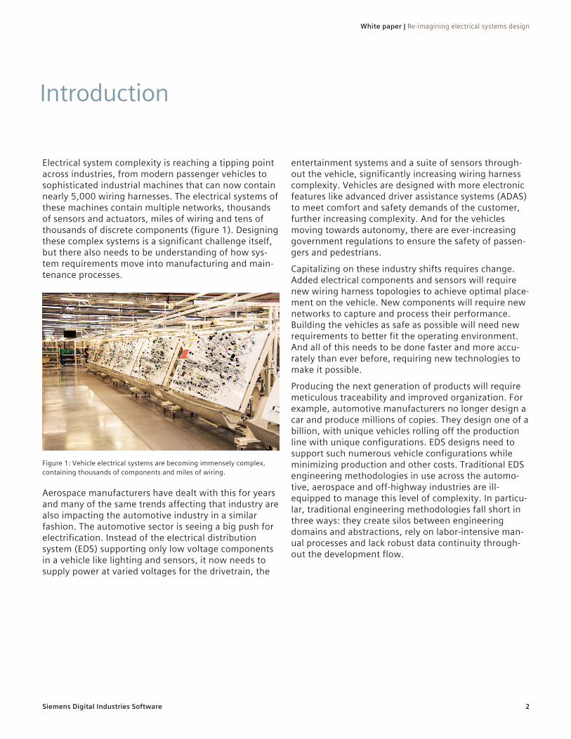
Electrical system complexity is reaching a tipping point across industries, from modern passenger vehicles to sophisticated industrial machines that can now contain nearly 5,000 wiring harnesses. The electrical systems of these machines contain multiple networks, thousands of sensors and actuators, miles of wiring and tens of thousands of discrete components (figure 1). Designing these complex systems is a significant challenge itself, but there also needs to be understanding of how sys-tem requirements move into manufacturing and main-tenance processes.
Aerospace manufacturers have dealt with this for years and many of the same trends affecting that industry are also impacting the automotive industry in a similar fashion. The automotive sector is seeing a big push for electrification. Instead of the electrical distribution system (EDS) supporting only low voltage components in a vehicle like lighting and sensors, it now needs to supply power at varied voltages for the drivetrain, the
entertainment systems and a suite of sensors through-out the vehicle, significantly increasing wiring harness complexity. Vehicles are designed with more electronic features like advanced driver assistance systems (ADAS) to meet comfort and safety demands of the customer, further increasing complexity. And for the vehicles moving towards autonomy, there are ever-increasing government regulations to ensure the safety of passen-gers and pedestrians.
Capitalizing on these industry shifts requires change. Added electrical components and sensors will require new wiring harness topologies to achieve optimal place-ment on the vehicle. New components will require new networks to capture and process their performance. Building the vehicles as safe as possible will need new requirements to better fit the operating environment. And all of this needs to be done faster and more accu-rately than ever before, requiring new technologies to make it possible.
Producing the next generation of products will require meticulous traceability and improved organization. For example, automotive manufacturers no longer design a car and produce millions of copies. They design one of a billion, with unique vehicles rolling off the production line with unique configurations. EDS designs need to support such numerous vehicle configurations while minimizing production and other costs. Traditional EDS engineering methodologies in use across the automo-tive, aerospace and off-highway industries are ill-equipped to manage this level of complexity. In particu-lar, traditional engineering methodologies fall short in three ways: they create silos between engineering domains and abstractions, rely on labor-intensive man-ual processes and lack robust data continuity through-out the development flow.
Figure 1: Vehicle electrical systems are becoming immensely complex, containing thousands of components and miles of wiring.
Introduction
White paper | Re-imagining electrical systems design
3Siemens Digital Industries Software
When tasked with designing an EDS and wiring harness for a new vehicle, there are four main stages to devel-opment for an electrical engineer. First, the engineer must define the electrical and electronic (E/E) architec-ture according to multi-domain requirements and the system-level architecture. For additional information on architectural definition, please download the whitepa-per: The advantages of MBSE-driven E/E architecture development. Next, detailed design work of the com-munication networks, embedded software, and EDS can begin. Though each of these systems could be designed from the ground up for the new vehicle, it is much more practical (and common) to reuse an existing design.
After verifying and validating the detailed designs, the next phase of development is creating the documenta-tion that will be needed to build the E/E vehicle compo-nents, such as the wiring harness. This documentation will include wiring implementations for every possible vehicle configuration; everything from a right-hand-drive entry-level model to a left-hand-drive premium package loaded with optional features must be sup-ported. It will also include a bill-of-materials and bill-of-processes (BoM/BoP) for manufacturing, which can be optimized for specific facilities.
The last phase occurs after the product has entered service and is being used by customers. At this stage, service documentation needs to be available for each of the vehicle configurations. This documentation will be used by service technicians to diagnose and repair electrical problems in the field. The accuracy and clarity of this documentation is critical to the quality and speed of vehicle repairs, which can make or break a customer experience with a vehicle.
In a traditional engineering flow, these development stages are connected only through ad hoc interactions and manual transfers of engineering data or drawings. The various electrical domains and other engineering disciplines, such as mechanical and software, operate in
silos with little to no visibility of the actions of other engineering teams. As a result, the traceability of data from vehicle requirements, to the functional abstraction and down to the eventual implementation in the wire harness is weak or entirely absent.
In contrast, a primary benefit of adopting a model-based approach is the ability to seamlessly leverage data from each of these stages to drive downstream processes. The architectural definition can be used by network, software, electrical and harness engineers to derive the necessary inputs to begin detailed work in each domain. Likewise, the detailed design from each electrical domain can be used, enriched and built upon for each downstream area and can be used to generate manufacturing and service documentation. A robust digital thread means that engineers no longer have to exchange this data manually, improving accuracy and ensuring the traceability of data throughout the devel-opment flow. The implementation of a model-based flow with an advanced electrical systems engineering solution, such as Capital, brings additional automation, analysis and multi-domain collaboration capabilities.
For example, consider the case of an EDS engineer tasked with implementing a new set of ADAS function-alities on an existing vehicle platform, as part of updates for the new model year of the vehicle. Having received the architectural definition for the new vehicle, in a model-based flow, the EDS engineer can compare the previous model design to the new architecture to identify changes, then follow the digital thread upstream to understand the motivation behind these changes. In this case, the power signal for the ADAS functions has switched from the ADAS controller to a body controller. The engineer can also follow the digital thread downstream to the wire harness for the outgo-ing model to understand how the updated architecture may affect that implementation.
The electrical design flow
White paper | Re-imagining electrical systems design
4Siemens Digital Industries Software
Generative design is critical to extracting the most out of a model-based development methodology. Generative design takes inputs from a variety of sources and automatically fuses them together to produce the required output for that stage, which can also be the input required for the next stage of development. To generate the EDS, the inputs will include the physical harness topology from the mechanical CAD (MCAD) environment, the product plan, logical system designs and a list of existing parts to reference.
Each of these inputs provides certain constraints on the potential output of the generative design. The harness topology from the MCAD environment provides physical constraints for the wiring and other harness compo-nents. For instance, the harness cannot be bigger than the hole through which it needs to be fed. The product plan inputs engineering and marketing constraints on vehicle features and options and how they can be com-bined. The logical systems design defines devices and connectivity, and a device interface list specifies the parts that should be used and their properties. Generative design then synthesizes wiring, connectors, splices and more to satisfy the required connectivity, physical dimensions and other constraints.
Understanding synthesisTo get a deeper understanding of how generative design works, consider the following simple example of wiring synthesis.
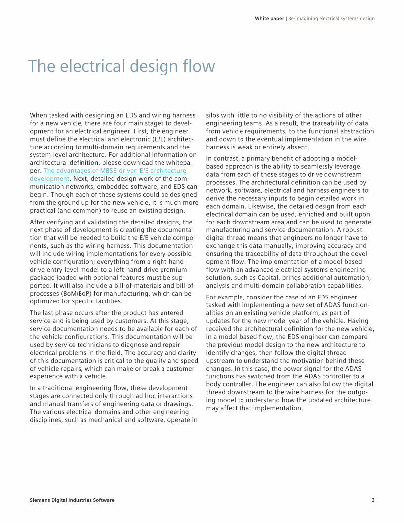
Figure 2 shows a two-dimensional view of a harness topology. In this example, the logical requirements mandate a connection between the four devices in teal, and the mechanical constraints define the possible pathways for wiring, shown in grey. Synthesis will find ways to connect all four devices that don’t violate any of the mechanical constraints. In this case, the devices on the far left are connected directly, then splices are used to connect the third and fourth devices in the topology. Further extracting value, wiring synthesis can optimize for implementations with the lowest cost. Cost is not only the material cost of the wire and components
being placed, but also logistical costs, such as the time saved by easily manufactured designs, or other user-defined metrics.
The true power of generative design is the speed with which it can synthesize optimized designs from the massively complex constraints of modern vehicles. For a complex system, synthesis may consider hundreds of millions of potential implementations, eliminating those that fail to meet requirements, and do so in a fraction of the time it would take a human engineer.
However, generative design can still produce millions of possible EDS implementations even with the design limitations and restrictions from the mechanical design, logical systems and other inputs. Additional refinement is required. The most effective means of further narrow-ing the design space is through the intellectual property (IP) engineers gather over years of experience.
Rules and intellectual propertyThe success of an engineering department is tightly linked to the collective experience of the individuals on the team. Through training and years of on-the-job experience, engineers develop a set of rules when
Figure 2: Generative design can synthesize wiring implementations based on defined rules and constraints.
Generative design: The heart of a model-based approach
White paper | Re-imagining electrical systems design
5Siemens Digital Industries Software
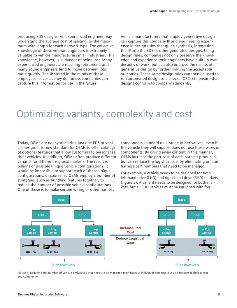
Today, OEMs are not synthesizing just one EDS or vehi-cle design. It is now standard for OEMs to offer catalogs of optional features that allow customers to personalize their vehicles. In addition, OEMs often produce different variants for different regional markets. The result is billions of possible unique vehicle configurations. It would be impossible to support each of these unique configurations, of course, so OEMs employ a number of strategies, such as bundling features together, to reduce the number of possible vehicle configurations. One of these is to make certain wiring or other harness
components standard on a range of derivatives, even if the vehicle they will support does not use these wires or components. By giving away content in this manner, OEMs increase the part cost of each harness produced, but can reduce the logistical cost by eliminating unique harness part numbers that need to be managed.
For example, a vehicle needs to be designed for both left-hand drive (LHD) and right-hand drive (RHD) markets (figure 3). A variant needs to be designed for both mar-kets, but all RHD vehicles must be equipped with fog
Figure 3: Reducing the number of vehicle derivatives that needs to be managed may increase individual part cost, but also reduces logistical cost and complexity.
Optimizing variants, complexity and cost
producing EDS designs. An experienced engineer may understand the average cost of splicing, or the maxi-mum wire length for each network type. The collective knowledge of these veteran engineers is extremely valuable to vehicle manufacturers in all industries. This knowledge, however, is in danger of being lost. Many experienced engineers are reaching retirement, and many young engineers tend to move between jobs more quickly. The IP stored in the minds of these employees leaves as they do, unless companies can capture this information for use in the future.
Vehicle manufacturers that employ generative design can capture this company IP and engineering experi-ence in design rules that guide synthesis, integrating the IP into the EDS or other generated designs. Using design rules, companies not only preserve the knowl-edge and experience their engineers have built up over decades of work, but can also improve the results of generative design by further limiting the acceptable outcomes. These same design rules can then be used to run automated design rule checks (DRCs) to ensure that designs conform to company standards.
White paper | Re-imagining electrical systems design
6Siemens Digital Industries Software
lights out of the factory while fog lights are optional for LHD vehicles. This simple case creates three derivative harnesses, which increases the number of components that need to be managed throughout production. Installing the fog lamp wiring on all LHD vehicles, regard-less of whether or not the fog lamp option was ordered, reduces the managed derivatives to two. This increases the part cost for each harness due to the added wiring, but reduces the logistical cost and variant complexity.
In the real world, OEMs manage thousands of vehicle variants across several regions. Manual complexity and cost calculations that are often based on assumed, ‘good enough’ values will not suffice in the future. In a model-based flow, these decisions can be based on data rather than assumptions. Vehicle models can be ana-lyzed to determine what content should be given away to achieve a balance between cost and complexity. Advanced E/E systems development solutions, such as Capital, provide robust metrics and performance indica-tors on cost, complexity and more to enable informed decisions on give-away and the optimal balance between part and logistical costs.
The rapid design iteration and robust analysis of flows may even drive changes in the business or
manufacturing model used by an OEM. Many companies operate on a model of composite and derivative har-nesses, in which every harness variant is assembled completely by the supplier before being sent to the OEM for installation in the vehicle. A modular harness manu-facturing model, on the other hand, involves pre-build-ing sets of sub-assemblies that are only assembled into a complete harness, based on the optional content selected, at the last minute before being installed in the vehicle. The harness modules can be reused across many different final assemblies, reducing the number of unique harnesses an OEM needs to manage.
With generative design, engineers can simply tell the E/E systems development software which business model to use and the software will generate models and other outputs to match. The engineers can perform further analyses, and even compare between business models to select the best option. The robust metrics provided by E/E systems development software then enable deeper understanding of the designs, creating a feedback loop of design generation and evaluation. These may include annualized cost projections, weight and more to drive correct decisions on both the harness implementation and business model used in production.
Achieving the engineering efficiency, excellence and speed needed to bring innovative products to market requires a methodology that promotes collaboration, automates processes and features robust traceability. Model-based approaches, implemented with an advanced portfolio of engineering software, provides these capabilities. They create an unbroken digital thread from vehicle requirements to functions and all the way to physical components on the vehicle. Such robust traceability ensures that vehicles leave produc-tion fully verified and validated, meeting all require-ments from the manufacturer, customers, and govern-ing authorities.
Furthermore, by implementing the model-based approach within an advanced electrical systems engi-neering solution, manufacturers of complex machinery can leverage generative design and robust metrics to rapidly create and assess designs. Within this flow, engineers can use generative design to integrate mod-els from various domains and produce an optimized output for downstream processes. These capabilities also support the optimization of harness cost and com-plexity associated with vehicle variants.
As products continue to become more complex, the traceability and accelerated development cycles pro-vided by this model-based approach and generative design will prove crucial to success.
Conclusion

Siemens Digital Industries Software
HeadquartersGranite Park One 5800 Granite Parkway Suite 600 Plano, TX 75024 USA +1 972 987 3000
AmericasGranite Park One 5800 Granite Parkway Suite 600 Plano, TX 75024 USA +1 314 264 8499
EuropeStephenson House Sir William Siemens Square Frimley, Camberley Surrey, GU16 8QD +44 (0) 1276 413200
Asia-PacificUnit 901-902, 9/FTower B, Manulife Financial Centre223-231 Wai Yip Street, Kwun TongKowloon, Hong Kong+852 2230 3333
siemens.com/software© 2020 Siemens. A list of relevant Siemens trademarks can be found here. Other trademarks belong to their respective owners.
82145-C2 6/20 N
About Siemens Digital Industries SoftwareSiemens Digital Industries Software is driving transformation to enable a digital enterprise where engineering, manufacturing and electronics design meet tomorrow. The Xcelerator portfolio helps companies of all sizes create and leverage digital twins that provide organizations with new insights, opportunities and levels of automation to drive innovation. For more information on Siemens Digital Industries Software products and services, visit www.sw.siemens.com or follow us on LinkedIn, Twitter, Facebook and Instagram. Siemens Digital Industries Software – Where today meets tomorrow.