Siemens RS232-FO Converter 7XV5652_Manual
28
RS232-FO Converter 7XV5652-0xA00 Operating Instructions Oct. 2006
Transcript of Siemens RS232-FO Converter 7XV5652_Manual

RS232-FO Converter 7XV5652-0xA00 Operating Instructions
Oct. 2006


Table of content 1 GENERAL INSTRUCTIONS ...........................................................................................................4
1.1 Qualified Personnel .....................................................................................................................5 1.2 Safety Notes ................................................................................................................................6 1.3 Intended Use ...............................................................................................................................7 1.4 Explanation of the symbols at the device:...................................................................................7 1.5 Exclusion of liability .....................................................................................................................8 1.6 Copyright .....................................................................................................................................8
2 OPERATING INSTRUCTIONS .......................................................................................................9
2.1 Scope of Application....................................................................................................................9 2.2 General Data ...............................................................................................................................9 2.3 Data Transfer.............................................................................................................................10 2.4 Connection of the FO Channel..................................................................................................10 2.5 Connection of the RS 232 Channel...........................................................................................10 2.6 Terminal Assignment 7XV5100-4 .............................................................................................10
3 TECHNICAL DATAS.....................................................................................................................11
3.1 Hardware features....................................................................................................................11 3.2 Safety Tests...............................................................................................................................12 3.3 Dielectric Tests ..........................................................................................................................13 3.4 Interference Emission................................................................................................................13 3.5 Interference immunity................................................................................................................14 3.6 Climatic Stress tests..................................................................................................................15 3.7 Mechanical Stress Tests ...........................................................................................................16 3.8 Dimension Drawings .................................................................................................................18 3.9 Ordering Data ............................................................................................................................18
4 DESCRIPTION OF THE FUNCTIONAL UNIT..............................................................................19
4.1 General description ...................................................................................................................19 4.2 Terminal Assignment.................................................................................................................19 4.3 Pin assignment X1, X2, X5........................................................................................................20 4.4 Switch positions.........................................................................................................................21
5 INSTALLATION AND COMMISSIONING ....................................................................................22
5.1 Reference to Installation............................................................................................................22 5.2 Connection ................................................................................................................................22
5.2.1 Voltage for operation – Auxilliary voltage .........................................................................23 5.2.2 Alarm relay terminals X5...................................................................................................23 5.2.3 Fibre Optic (FO) connections ...........................................................................................23 5.2.4 RS232 connection ............................................................................................................24
5.3 Commissioning..........................................................................................................................24 5.4 Maintenance ..............................................................................................................................24
6 APPLICATIONS ............................................................................................................................25
6.1 Optical star-structur for devices V3 with RS232-Interface ........................................................25 6.2 Data communication for Digital Differential Protection Relays with FO-Interface.....................26
12.10.2006 RS232-FO Converter Page 3 of 28

1 General Instructions This manual includes the information required for the normal use of the products described therein. It is intended for technically qualified personnel which has been specially trained or has special knowledge in the fields of protection-, instrumentation-, control-, and automatic control engineering (called automation in the following). The knowledge and the technically correct translation of the safety instructions and warnings included in this manual are a prerequisite for the safe installation and commissioning, as well as for safety during operation and maintenance, of the product described. Only qualified personnel, as defined in the following explanation, possess the technical knowledge required to interpret correctly and to put into action for each individual case the safety instructions and warnings given in this document in a general manner. This manual is an integral part of the scope of delivery. However, it cannot take into account every detail on all types of the described product and also every possible case regarding installation, operation or maintenance. If further information is desired or in case special problems should arise, which are not treated adequately in this document, it is possible to obtain additional details from the local Siemens office or from the addresses stated in the back of this manual. Additionally, we point out that the content of this product documentation is not part of or modifies any previous or existing agreement, promise, or legal relationship. All obligations by Siemens result from the respective purchase order which also includes the complete and exclusively valid warranty provision. The contractual warranty regulations are neither extended nor limited by the statements in this document.
Page 4 of 28 RS232-FO Converter 12.10.2006

1.1 Qualified Personnel Tampering with the device/system or noncompliance with the safety notices given in this manual may cause severe bodily injury or property damage. Therefore any interventions on the device/system may only be performed by adequately qualified personnel. Qualified personnel as per the safety notices given in these instructions or on the product itself is: • personnel involved in planning and configuration activities and familiar with the safety concepts used in automation engineering; • operating personnel trained for working with automation systems and familiar with the content of this manual as far as it deals with operational aspects; • commissioning and service personnel having adequate training and qualification to repair this type of automation equipment and/or having authorization to commission, release, ground and tag devices, systems and electrical circuits.
12.10.2006 RS232-FO Converter Page 5 of 28
1.2 Safety Notes These operating instructions contain notes that are to be complied with for your personal safety as well as to avoid property damages. These notes are marked by a triangular warning symbol and the different degrees of danger are categorized as follows: Danger
Disregard of the corresponding precautionary measures will cause death, severe bodiliy injury or considerable property damage.
Warning Disregard of the corresponding precautionary measures may cause death, severe bodiliy injury or considerable property damage.
Attention Disregard of the corresponding precautionary measures may lead to slight bodiliy injury or minor property damage
Note Shall draw your attention to special information on the product, product handling or the corresponding section of the documentation.
Qualified personnel Commissioning and operation of the equipment is to be performed by qualified personnel only. In the context of safety notes in this manual, the term qualified personnel refers to persons authorized to perform commissioning, grounding and labelling of devices, systems and electrical circuits.
Page 6 of 28 RS232-FO Converter 12.10.2006
1.3 Intended Use Please observe the following Warning
The device must be operated only within the scope of its intended use according to these operating instructions and in connection with third-party equipment or compounds recommended or accepted by Siemens. Faultless and safe operation of the product require proper transport, storage, mounting and installation as well as careful operation and maintenance.
1.4 Explanation of the symbols at the device:
Danger Warning of a danger. Please read the documentation. To be operated only by qualified personnel.
Double insulation
12.10.2006 RS232-FO Converter Page 7 of 28

1.5 Exclusion of liability The contents of this document have been reviewed on their compliance with the hardware and software described therein. Yet, deviations cannot be excluded, so that we cannot guarantee full compliance. The specifications in this document are, however, reviewed at regular intervals. Necessary corrections will be included in the next edition. You are invited to send us your suggestions for improvement.
1.6 Copyright Copyright Siemens AG 2000. All rights reserved. Transmission or reproduction of this document, as well as the use and forwarding of its contents is not permitted without express written authority. Offenders will be liable for damages. All rights, including rights created by patent grant or registration of a utility model or design, are reserved. Subject to technical changes without notice.
Page 8 of 28 RS232-FO Converter 12.10.2006

2 Operating Instructions
2.1 Scope of Application The RS232 / FO Converter is used for converting RS232 signals to signals for FO conductors with BOFC ST-connectors. It is equipped with one FO channel and one RS232 channel and switches automatically from ”FO receiving data” to ”FO transmitting data”. A power supply is integrated in the housing to generate the voltage required for the converter board from the auxiliary power supply. The RS232 / FO converter can be used for transmission rates up to 115200 bauds.
2.2 General Data The signal converter has a plastic housing that can be snapped onto a DIN EN 50022 mounting rail. The auxiliary power supply is fed in via two terminals. Because of ist extremely wide auxiliary voltage range (DC 24-250V and AC 60-250V), the converter can be connected without switchover to all common types of station batteries and AC mains voltage supplies. The front cover has a green LED for indication of the operating voltage status. The status of the internal +5V operating voltage can be checked by means of a potential-free relay contact that is brought out to two terminals. An open contact means that the operating voltage is o.k. The readiness for service of the unit is indicated by means of a potential-free signalling contact (terminals 1,2) that can be used to communicate the following fault conditions to a control center: • No supply voltage • Failure of internal power supply When a fault condition is present, the contact is closed.
12.10.2006 RS232-FO Converter Page 9 of 28
2.3 Data Transfer The logic of the optical interface is positive (Light OFF in idle state), incoming light signals are treated as active = 1 (high). For use in systems operating with a negative logic, the converter can be switched over to negative logic by means of a switch that is accessible from outside. Inversion of the logic applies to both the optical output and the RS232 interface output. On delivery, the converter is set to positive logic (Light OFF in idle state).
2.4 Connection of the FO Channel The FO cables are connected to the corresponding FO elements. The connector type is BOFC (ST). When wiring FO cables, the specified bending radius must be observed.
2.5 Connection of the RS 232 Channel The RS232 channel is connected by a special RS232 cable with 9-pin Sub-D male connector.
2.6 Terminal Assignment 7XV5100-4 The serial connection cable ´DIGSI-cable´ connects a 9-pole serial PC-interface (e.g. COM1) with the serial interface of the relay or a starcoupler or a converter, which have also a 9-pole serial interface.. The following devices have a 9-pole serial interface: 7SJ531, 7SJ602 and all SIPROTEC 4 devices, e.g. 7SA522, 7SD52, 7SA6x, 7SJ61/62/63, 6MD6x, ... . In addition the starcouplers 7XV5300, 7XV5450, 7XV5550 and the converter 7XV5652 are directly connected with this cable.
23
46
7*8*
5
32TxD
RxD
GND
7XV5100-4Notebook / PC9pol. Socket
Device9pol. Plug
* for Starcoupler78
5
Length 3m
Fig. 2: Terminal Assignment 7XV5100-4
Page 10 of 28 RS232-FO Converter 12.10.2006
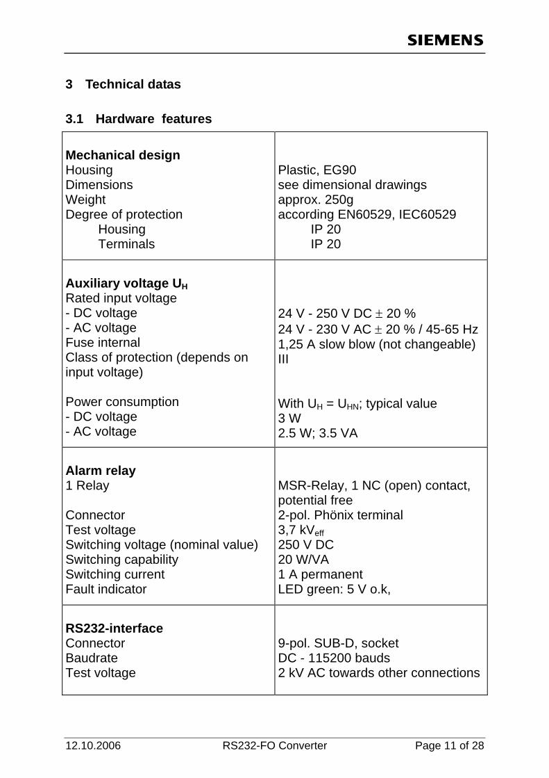
3 Technical datas
3.1 Hardware features Mechanical design Housing Dimensions Weight Degree of protection Housing Terminals
Plastic, EG90 see dimensional drawings approx. 250g according EN60529, IEC60529 IP 20 IP 20
Auxiliary voltage UH Rated input voltage - DC voltage - AC voltage Fuse internal Class of protection (depends on input voltage) Power consumption - DC voltage - AC voltage
24 V - 250 V DC ± 20 % 24 V - 230 V AC ± 20 % / 45-65 Hz 1,25 A slow blow (not changeable) III With UH = UHN; typical value 3 W 2.5 W; 3.5 VA
Alarm relay 1 Relay Connector Test voltage Switching voltage (nominal value) Switching capability Switching current Fault indicator
MSR-Relay, 1 NC (open) contact, potential free 2-pol. Phönix terminal 3,7 kVeff250 V DC 20 W/VA 1 A permanent LED green: 5 V o.k,
RS232-interface Connector Baudrate Test voltage
9-pol. SUB-D, socket DC - 115200 bauds 2 kV AC towards other connections
12.10.2006 RS232-FO Converter Page 11 of 28

Optical interfaces Optical inputs / outputs Optical connectors Laser class 1 acc. EN60825-1/-2 Data flow indication Wave length Launched power Sensitivity Optical budget Maximum distance spanned Baud rates
1 transmitter, 1 receiver Factory setting: Light OFF in idle state BFOC ST-connectors (plastic protective caps) none 820 nm -19dBm with 50/125µm multimode fibre -15dBm with 62,5/125µm multimode fibre -6,2dBm with 200µm HCS fibre -30dBm 10dB (+3 dB system budget- safety margin) 3.0 km with 62,5/125µm multimode fibre 1.5 km in combination with SIPROTEC systems with 62,5/125µm multimode fibre 3.5 m with 980/1000 plastic fibre DC - 115200 Baud
3.2 Safety Tests Safety tests according DIN EN 61010 Teil1 Overvoltage category Degree of pollution Fire resistance classification according to UL 94
III 2 V0
Page 12 of 28 RS232-FO Converter 12.10.2006

3.3 Dielectric Tests Dielectric tests EN61010 IEC 255-5: ANSI/IEEE C37.90.0 Voltage test (routine test) Auxiliary power to relay Auxiliary power to RS232 interface Relay to RS232 interface Surge voltage test (type test) VDE 0435, Pt. 303 Auxiliary power to relay Auxiliary power to RS232 interface Relay to RS232 interface
5,25 kV DC / 1s (with bypass capacitors) 3,7 kV AC / 50Hz / 1s (without bypass capacitors) 5 kV (peak); 1,2/50 µs; 0,5 J; 3 pos. and 3 neg. surges in intervals of 5 s all circuits, class III (not on open contacts)
3.4 Interference Emission Interference Emission Standard: EN 50081-1 Conducted interference, only power supply voltage IEC CISPR 22, EN55022 VDE 0878 Teil 22 Radio interference field strength IEC CISPR 22, EN55022 VDE 0878 Teil 22
150 kHz to 30 MHz Limit class B Limit class B 30 MHz to 1000 MHz Limit class B Limit class B
12.10.2006 RS232-FO Converter Page 13 of 28
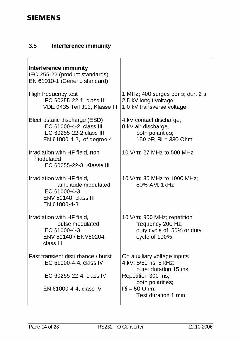
3.5 Interference immunity Interference immunity IEC 255-22 (product standards) EN 61010-1 (Generic standard) High frequency test
IEC 60255-22-1, class III VDE 0435 Teil 303, Klasse III
Electrostatic discharge (ESD)
IEC 61000-4-2, class III IEC 60255-22-2 class III EN 61000-4-2, of degree 4
Irradiation with HF field, non
modulated IEC 60255-22-3, Klasse III
Irradiation with HF field,
amplitude modulated IEC 61000-4-3 ENV 50140, class III EN 61000-4-3
Irradiation with HF field,
pulse modulated IEC 61000-4-3 ENV 50140 / ENV50204, class III
Fast transient disturbance / burst
IEC 61000-4-4, class IV
IEC 60255-22-4, class IV
EN 61000-4-4, class IV
1 MHz; 400 surges per s; dur. 2 s 2,5 kV longit.voltage; 1,0 kV transverse voltage 4 kV contact discharge, 8 kV air discharge, both polarities; 150 pF; Ri = 330 Ohm 10 V/m; 27 MHz to 500 MHz 10 V/m; 80 MHz to 1000 MHz; 80% AM; 1kHz 10 V/m; 900 MHz; repetition frequency 200 Hz; duty cycle of 50% or duty cycle of 100% On auxiliary voltage inputs 4 kV; 5/50 ns; 5 kHz; burst duration 15 ms Repetition 300 ms; both polarities; Ri = 50 Ohm; Test duration 1 min
Page 14 of 28 RS232-FO Converter 12.10.2006

Fast transient disturbance / burst
IEC 61000-4-4, Klasse III IEC 60255-22-4, Klasse III EN 61000-4-4, Klasse III
Line contucted HF, amplitude
modulated IEC 61000-4-6, class III
EN 61000-4-6, class III Immunity to power frequency
magnetic field EN 61000-4-8, class IV
On signal lines 2 kV; 5/50 ns; 5 kHz; burst duration 15 ms Repetition 300 ms; both polarities; Ri = 50 Ohm; Test duration 1 min 10 V; 150 kHz to 80 MHz; 80% AM; 1 kHz 30 A/m, permanent; 300 A/m during 3 s; 50 Hz
3.6 Climatic Stress tests Ambient Temperatures EN 60068-2-1 and -2-2 Recommended operating temperature Limiting temporary (transient) operating Limiting temperatutre during storage (packing from the factory) Limiting temperature during transport (packing from factory) Permissible humidity
-5°C to +55°C (+23° F to +131°F) -20°C to +70°C (-4° F to +158°F) -25°C to +55°C (-13° F to +131°F) -25°C to +70°C (-13° F to +158°F) mean value per year < 75% relative humidity, 30 days per yaer 95% rel. humidity,condensation not permissible!
12.10.2006 RS232-FO Converter Page 15 of 28
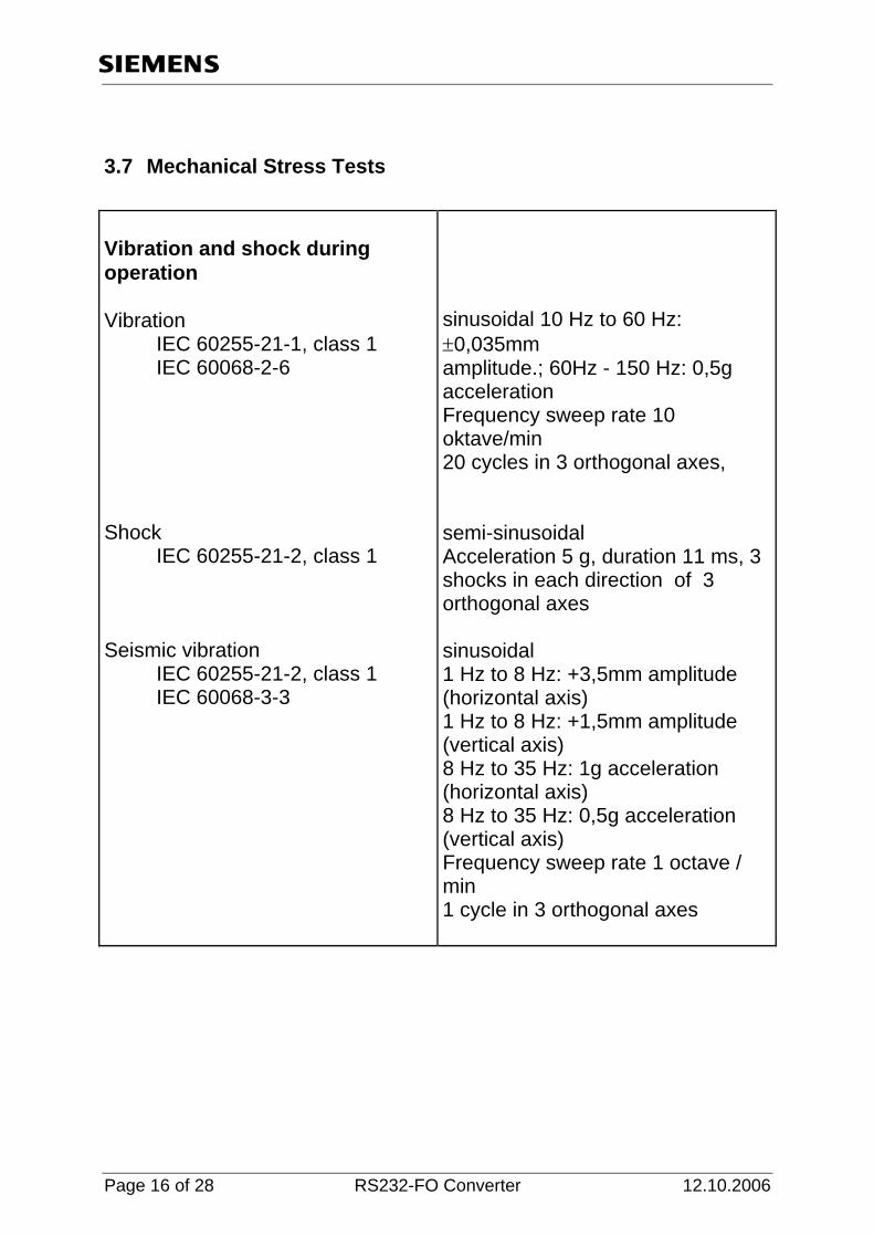
3.7 Mechanical Stress Tests Vibration and shock during operation Vibration IEC 60255-21-1, class 1 IEC 60068-2-6 Shock IEC 60255-21-2, class 1 Seismic vibration IEC 60255-21-2, class 1 IEC 60068-3-3
sinusoidal 10 Hz to 60 Hz: ±0,035mm amplitude.; 60Hz - 150 Hz: 0,5g acceleration Frequency sweep rate 10 oktave/min 20 cycles in 3 orthogonal axes, semi-sinusoidal Acceleration 5 g, duration 11 ms, 3 shocks in each direction of 3 orthogonal axes sinusoidal 1 Hz to 8 Hz: +3,5mm amplitude (horizontal axis) 1 Hz to 8 Hz: +1,5mm amplitude (vertical axis) 8 Hz to 35 Hz: 1g acceleration (horizontal axis) 8 Hz to 35 Hz: 0,5g acceleration (vertical axis) Frequency sweep rate 1 octave / min 1 cycle in 3 orthogonal axes
Page 16 of 28 RS232-FO Converter 12.10.2006
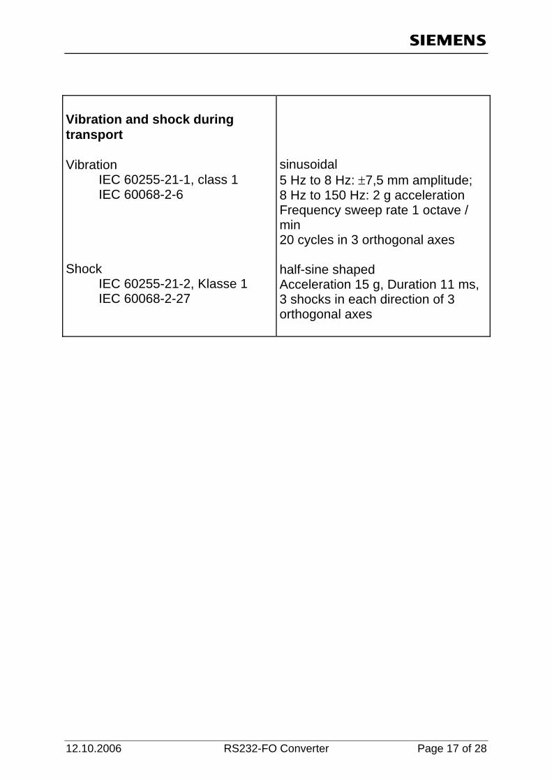
Vibration and shock during transport Vibration IEC 60255-21-1, class 1 IEC 60068-2-6 Shock IEC 60255-21-2, Klasse 1 IEC 60068-2-27
sinusoidal 5 Hz to 8 Hz: ±7,5 mm amplitude; 8 Hz to 150 Hz: 2 g acceleration Frequency sweep rate 1 octave / min 20 cycles in 3 orthogonal axes half-sine shaped Acceleration 15 g, Duration 11 ms, 3 shocks in each direction of 3 orthogonal axes
12.10.2006 RS232-FO Converter Page 17 of 28

3.8 Dimension Drawings
N/L-RS 232
RS232-LWL-Converter 7XV5652-0AA00SERIES: A4-K7-655430
C E 55
24-250V DC60-230V AC
RU
N
T1 R1
UH
UHL1/L+12
M1
90
75
105
90
90
Fig. 3: Dimension Drawings
3.9 Ordering Data Name Order-No.
RS232-FO Converter 7 X V 5 6 5 2 - 0 A 0 0With 1 FO-Interface and 1 RS232- Interface Optical inputs / outputs
BOFC-connector (ST-connector) B
Page 18 of 28 RS232-FO Converter 12.10.2006
4 Description of the Functional Unit
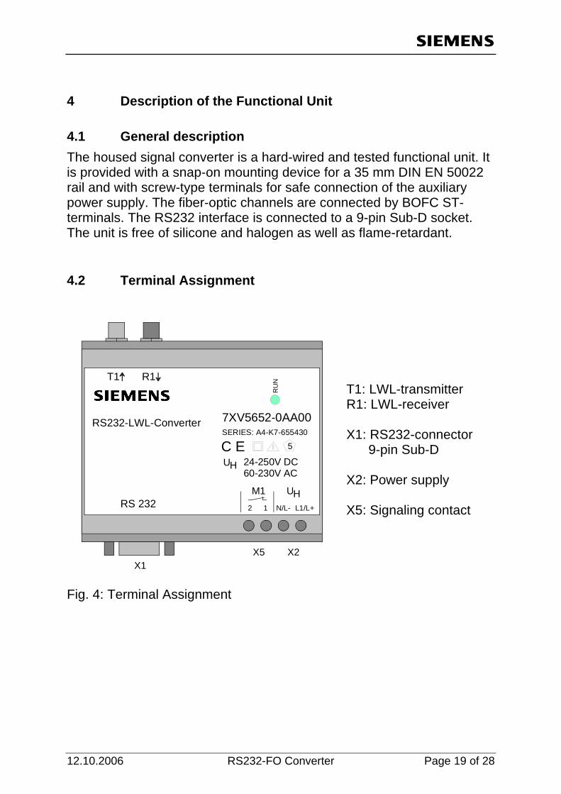
4.1 General description The housed signal converter is a hard-wired and tested functional unit. It is provided with a snap-on mounting device for a 35 mm DIN EN 50022 rail and with screw-type terminals for safe connection of the auxiliary power supply. The fiber-optic channels are connected by BOFC ST- terminals. The RS232 interface is connected to a 9-pin Sub-D socket. The unit is free of silicone and halogen as well as flame-retardant.
4.2 Terminal Assignment
N/L-RS 232
RS232-LWL-Converter 7XV5652-0AA00SERIES: A4-K7-655430
C E 55
24-250V DC60-230V AC
RU
NT1 R1
UH
UHL1/L+12
M1
X1X2X5
T1: LWL-transmitter R1: LWL-receiver X1: RS232-connector 9-pin Sub-D X2: Power supply X5: Signaling contact
Fig. 4: Terminal Assignment
12.10.2006 RS232-FO Converter Page 19 of 28

4.3 Pin assignment X1, X2, X5
Pin Assignment Symbol X2 X2
Power supply Power supply
DC: L+ AC: L1 DC: L- AC: N
X5 X5
Relay contact 1 Relay contact 2
1 2
Tab. 1: Screw-type terminals X2, X5
Pin Assignment Symbol Data direction when used as DTE
1 nc 2 Receive Data RxD In 3 Transmit Data TxD Out 4 nc 5 Signal ground GND GND 6 nc 7 nc 8 nc 9 nc
Tab. 2: 9-pin Sub-D socket X1
Page 20 of 28 RS232-FO Converter 12.10.2006
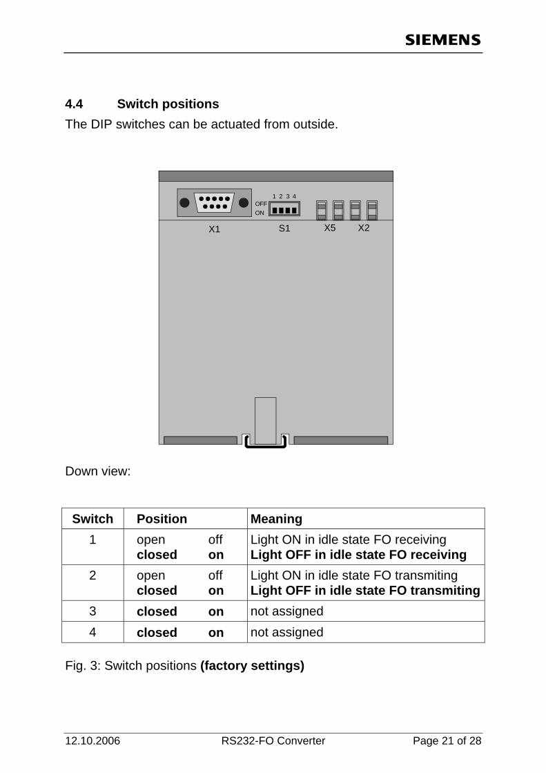
4.4 Switch positions The DIP switches can be actuated from outside.
OFF1 2
X1 X2X5S1
3 4
ON
Down view: Switch Position Meaning
1 open off closed on
Light ON in idle state FO receiving Light OFF in idle state FO receiving
2 open off closed on
Light ON in idle state FO transmiting Light OFF in idle state FO transmiting
3 closed on not assigned 4 closed on not assigned
Fig. 3: Switch positions (factory settings)
12.10.2006 RS232-FO Converter Page 21 of 28

5 Installation and Commissioning Warning
When operating electrical devices, certain parts are necessarily under dangerous voltage. Therefore, disregard of the operating notes may cause servere bodily injury or property damage. Installation and electrical connection of the device should be performed by adequately qualified personnel only. In particular, all warnings must be strictly observed.
WARNING Do not look directly in the FO-transmitter diodes T1 – T5 if you wear optical aid (glasses, contact lens)
5.1 Reference to Installation
• The devices are permitted only for operation within enclosed housings or cabinets and places of installation are to be accessible only for qualified personnel.
• The device is clipped on a 35 mm top-hat rail (according to EN50022).
• The installation location should be free of vibrations. The admissible temperature (operation or functional temperature) is to be observed (see technical data).
• Disregard of the temperature range required for proper function may cause malfunction, failure or destruction of the device.
5.2 Connection The chapter ´Connection´ decribe how to connect data- and power supply cables for a save operation. For the electrical connection the regulations on the raise of heavy-current installations are to be observed.
Warning Any connections with litz wire are to be realized with the help of wire end ferrules.
Page 22 of 28 RS232-FO Converter 12.10.2006

5.2.1 Voltage for operation – Auxilliary voltage The wires for the auxilliary voltage are screwed on terminal X2 at he bottom side of the device. The assignment of the terminals is printed at the front side or can be read in this manual. Because the device has no ON/OFF switch this switch must be installed external if it´s necessary. Connection to screw terminals: Terminal cross section: max. 2,5 mm2
Stripping length: 3 bis 5 mm Cable cross section: 0,14 bis 1,5 mm2
(Single core cable or litz wire)
5.2.2 Alarm relay terminals X5 X5 offers a potential free contact, which is closed if the device fails. The loss of the power supply is a device failure. The wires for the alarm contacts are screwed on terminal X7 at he bottom side of the device. The assignment of the terminals is printed at the front side or can be read in this manual. Connection to screw terminals: Terminal cross section: max. 2,5 mm2
Stripping length: 3 bis 5 mm Cable cross section: 0,14 bis 1,5 mm2
(Single core cable or litz wire)
5.2.3 Fibre Optic (FO) connections
• Only optical fibres prepared according the regulations are to be used. The admissible optical budget is to be observed
• FO-types (only multimode) and max. distance see technical datas. • Transmitter diodes are printed with Tx. • Receiver diodes are printed with Rx. • The FO-cables must be crossed, that means a FO-connection is
done between Tx output and Rx input and vice versa.
Note When installing optical fibres the prescripted bending radius is to be observed.
12.10.2006 RS232-FO Converter Page 23 of 28
5.2.4 RS232 connection • After the connection of a serial cable to the 9 pole Sub-D connector
at the device (X1) it should be screwed. For temporally use it´s not necessary to screw it. But please check if it´s connected.
5.3 Commissioning
• Clip the Active Mini-Starcoupler on the top–hat rail according EN 50022 with the help of clip-on mounting. Do not make any changes at the device.
• Check whether the operation data comply with the values on the rating plate. Not change any DIP-switch at the device, before reading this manual.
• Connect FO cable to FO receiver (Rx) and FO transmitter (Tx) with the help of ST-plugs. Be carefull when connecting the FO plugs and avoid any dust at the FO – connections.
• Connect to RS485 and RS232 terminals and screw them for permanent use.
• Connect the alarm relay terminals X5. • Connect auxiliary power to the terminals X2 (DC: L+ / AC: L1 and
DC: L- / AC: N). • The device is ready for use after switching on the auxiliary power.
The green LED `RUN´ lights up.
5.4 Maintenance The signal converter requires no maintanance. For cleaning please use a dry and free of fuzz rag. Put the caps onto the FO-interfaces to avoid dust pollution and interference from sun light or any artifical light source. Do not use any liquid agents or substances for cleaning.
Page 24 of 28 RS232-FO Converter 12.10.2006

6 Applications
6.1 Optical star-structur for devices V3 with RS232-Interface In an existing optical star structure with starcouplers version 3 devices with an electrical RS232-interface can be connected by converting from electrical to optical with 7XV5652-converters.
DIGSI
SIPROTEC SIEMENS
L1 402,1A Max450.1AL2 402,1A Max450.1AL3 402,1A Max450.1AE 00.0A
Anr. L1 Anr. L2
Anr. L3
Anr. Erde
Automat
RUN ERROR
LWLRS232
LWLLWLLWLLWL
Mini-Starcoupler 7XV5450
L2 402,1A Max450.1AL3 402,1A Max450.1A
LWL
RS232
Converter 7XV5652
LWL
RS232
Converter 7XV5652
DIGSI
Modem7XV
5101
Substation modem7XV58xx
Modem
Office modem7XV58xx
Public Network
V3V4
FO-Cable 6XV81
DIGSI-Cable7XV5100-4
SIPROTEC Devices
Converter7XV5101-0B
L2 402,1A Max450.1AL3 402,1A Max450.1A L2 402,1A Max450.1A
L3 402,1A Max450.1A
V3 V3
Fig. 6: Optical star-structur for devices V3 with RS232-Interface
12.10.2006 RS232-FO Converter Page 25 of 28
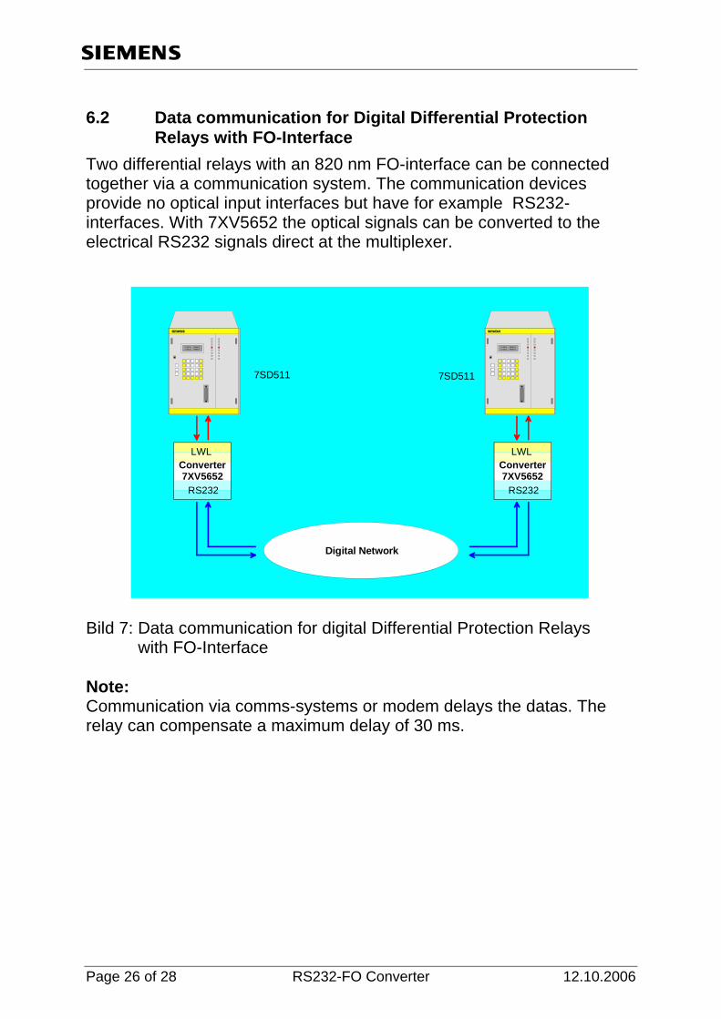
6.2 Data communication for Digital Differential Protection Relays with FO-Interface
Two differential relays with an 820 nm FO-interface can be connected together via a communication system. The communication devices provide no optical input interfaces but have for example RS232-interfaces. With 7XV5652 the optical signals can be converted to the electrical RS232 signals direct at the multiplexer.
RS232
LWLConverter7XV5652
L2 402,1A Max450.1AL3 402,1A Max450.1A
L2 402,1A Max450.1AL3 402,1A Max450.1A
RS232
LWLConverter7XV5652
Digital Network
7SD511 7SD511
Bild 7: Data communication for digital Differential Protection Relays with FO-Interface Note: Communication via comms-systems or modem delays the datas. The relay can compensate a maximum delay of 30 ms.
Page 26 of 28 RS232-FO Converter 12.10.2006
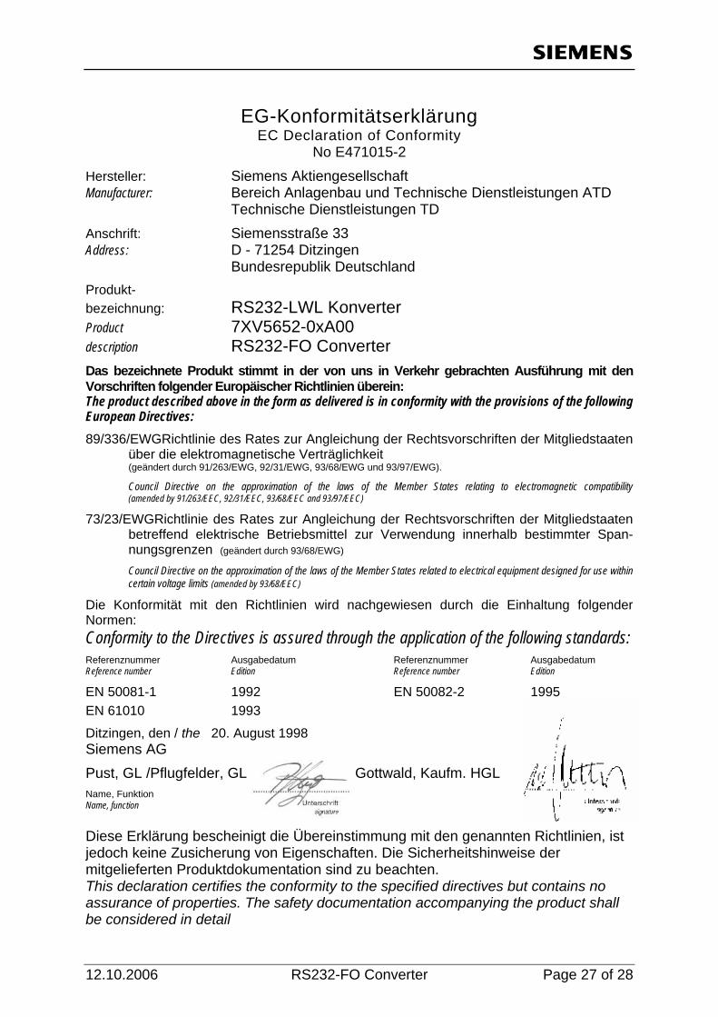
EG-Konformitätserklärung EC Declaration of Conformity
No E471015-2 Hersteller: Siemens Aktiengesellschaft Manufacturer: Bereich Anlagenbau und Technische Dienstleistungen ATD Technische Dienstleistungen TD Anschrift: Siemensstraße 33 Address: D - 71254 Ditzingen Bundesrepublik Deutschland Produkt- bezeichnung: RS232-LWL Konverter Product 7XV5652-0xA00 description RS232-FO Converter Das bezeichnete Produkt stimmt in der von uns in Verkehr gebrachten Ausführung mit den Vorschriften folgender Europäischer Richtlinien überein: The product described above in the form as delivered is in conformity with the provisions of the following European Directives: 89/336/EWGRichtlinie des Rates zur Angleichung der Rechtsvorschriften der Mitgliedstaaten
über die elektromagnetische Verträglichkeit (geändert durch 91/263/EWG, 92/31/EWG, 93/68/EWG und 93/97/EWG).
Council Directive on the approximation of the laws of the Member States relating to electromagnetic compatibility (amended by 91/263/EEC, 92/31/EEC, 93/68/EEC and 93/97/EEC)
73/23/EWGRichtlinie des Rates zur Angleichung der Rechtsvorschriften der Mitgliedstaaten betreffend elektrische Betriebsmittel zur Verwendung innerhalb bestimmter Span-nungsgrenzen (geändert durch 93/68/EWG)
Council Directive on the approximation of the laws of the Member States related to electrical equipment designed for use within certain voltage limits (amended by 93/68/EEC)
Die Konformität mit den Richtlinien wird nachgewiesen durch die Einhaltung folgender Normen: Conformity to the Directives is assured through the application of the following standards: Referenznummer Ausgabedatum Referenznummer Ausgabedatum Reference number Edition Reference number Edition
EN 50081-1 1992 EN 50082-2 1995 EN 61010 1993
Ditzingen, den / the 20. August 1998 Siemens AG Pust, GL /Pflugfelder, GL Gottwald, Kaufm. HGL Name, Funktion Name, function Diese Erklärung bescheinigt die Übereinstimmung mit den genannten Richtlinien, ist jedoch keine Zusicherung von Eigenschaften. Die Sicherheitshinweise der mitgelieferten Produktdokumentation sind zu beachten. This declaration certifies the conformity to the specified directives but contains no assurance of properties. The safety documentation accompanying the product shall be considered in detail
12.10.2006 RS232-FO Converter Page 27 of 28

If you have any notes or questions on this product please contact us under the following address: Siemens AG Power Transmission and Distribution Power Automation Depart. PTD PA 13 Postfach 4806 D-90026 Nürnberg Telefax (+49 911) 433-8301 Further informations regarding our products in the INTERNET under:
http://www.SIPROTEC.com.
or please visit our Download Area which is part of our WEB-site, where also the latest version of this manual is available as a PDF-file. Printed in Germany