Basics of Sensors - Siemens Ww(Industrial Automation Sensors)
This document includes confidential data that shall not be duplicated, used, distributed, or disclosed for any purpose unless authorized by Siemens.
SIEMENS Process Sensors
This document includes confidential data that shall not be duplicated, used, distributed, or disclosed for any purpose unless authorized by Siemens.
Understanding Ultrasonic/ Non-Contact Level June 2011

Page 204/01/2011 Siemens Industry Inc.Confidential - for Siemens authorized use only.
L. BARKER CWTRS_UU.ppt
Introduction / Contents
The Technology Leader as Your Partner
The standards regarding the conservation and quality of water are steadily rising and regulations are becoming increasingly stringent. Our role is to help ensure your water management operations meet these requirements.
ContentsUltrasonic TechnologyUltrasonic Theory & Echo RangingTroubleshooting Ultrasonic'sMounting ConsiderationsApplications

Page 304/01/2011 Siemens Industry Inc.Confidential - for Siemens authorized use only.
L. BARKER CWTRS_UU.ppt
Level Measurement Technologies
UltrasonicAdvantage
Ease of installationNo contact with the processLittle or no maintenanceProven in many applicationsTypically lowest cost of non-contacting technologies
Page 404/01/2011 Siemens Industry Inc.Confidential - for Siemens authorized use only.
L. BARKER CWTRS_UU.ppt
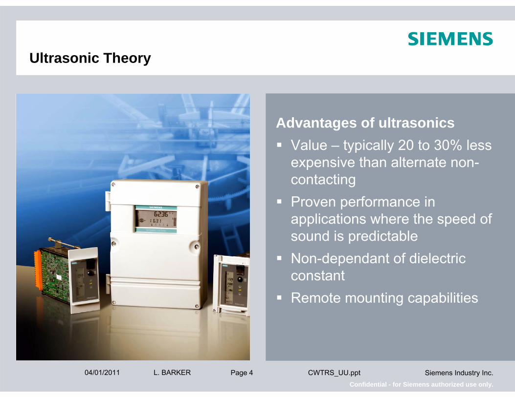
Ultrasonic Theory
Advantages of ultrasonicsValue – typically 20 to 30% less expensive than alternate non-contactingProven performance in applications where the speed of sound is predictableNon-dependant of dielectric constantRemote mounting capabilities

Page 504/01/2011 Siemens Industry Inc.Confidential - for Siemens authorized use only.
L. BARKER CWTRS_UU.ppt
Level Measurement Technologies
UltrasonicDisadvantage
Poorly reflective surfacesMust “see” the levelSusceptibility to changes in air space the attenuate the speed of sound

Page 604/01/2011 Siemens Industry Inc.Confidential - for Siemens authorized use only.
L. BARKER CWTRS_UU.ppt
Level Measurement – Application Chart
Measurement range
Changing vapors
Heavy dust //////
Turbulence
Interface
Slurries
Solids
Liquids 3PPPP
Ultrasonics NON-CONTACTING
Microwave Radar
NON-CONTACTING
Guided Wave Radar
CONTACTING
Capacitance CONTACTING
Differential Pressure CONTACTING
Application Variable

Page 704/01/2011 Siemens Industry Inc.Confidential - for Siemens authorized use only.
L. BARKER CWTRS_UU.ppt
Level Measurement – Application Chart
Dielectric ≤ 1.4
Accuracy ≥ 2%
Variable fluid density
Variable dielectric
Pressure >60 psi
Cryogenics
Vacuum
Temperature >300°F 3PPPP
Ultrasonics NON-CONTACTING
Microwave Radar
NON-CONTACTING
Guided Wave Radar
CONTACTING
Capacitance CONTACTING
Differential Pressure CONTACTING
Application Variable

This document includes confidential data that shall not be duplicated, used, distributed, or disclosed for any purpose unless authorized by Siemens.
Ultrasonic Technology Questions?
This document includes confidential data that shall not be duplicated, used, distributed, or disclosed for any purpose unless authorized by Siemens.
SIEMENS Process Sensors
This document includes confidential data that shall not be duplicated, used, distributed, or disclosed for any purpose unless authorized by Siemens.
Basic Ultrasonic Theory

Page 1004/01/2011 Siemens Industry Inc.Confidential - for Siemens authorized use only.
L. BARKER CWTRS_UU.ppt
Ultrasonic Theory
The nature of soundSound is a series of compression waves that travel through air or many other materials
Sound waves are caused by the vibrating of some objectSound must cause another object to vibrate to be detected

Page 1104/01/2011 Siemens Industry Inc.Confidential - for Siemens authorized use only.
L. BARKER CWTRS_UU.ppt
Ultrasonic Theory
The nature of soundSound waves have characteristics just like any other wave
VelocityWave LengthFrequencyAmplitude

Page 1204/01/2011 Siemens Industry Inc.Confidential - for Siemens authorized use only.
L. BARKER CWTRS_UU.ppt
Ultrasonic Theory
The nature of soundVelocity refers to the direction and speed of soundThe speed of sound is determined by the
Medium type (gas, water, solid)Temperature of the mediumMedium stratificationVacuum

Page 1304/01/2011 Siemens Industry Inc.Confidential - for Siemens authorized use only.
L. BARKER CWTRS_UU.ppt
Ultrasonic Theory
Low Frequency
High Frequency
1 second
The nature of soundWavelength is a measurement of the distance from one crest to anotherFrequency refers to the vibration of pitch of a sound
Measured in Hertz (Hz)The rate at which a guitar string or loud speaker vibrates
Since the velocity of sound is approximately the same for all wavelengths, frequency is often used to better describe the effects of different wavelengths.

Page 1404/01/2011 Siemens Industry Inc.Confidential - for Siemens authorized use only.
L. BARKER CWTRS_UU.ppt
Ultrasonic Theory
The nature of soundThe amplitude of sound is related to sound intensity (loudness)
Amplitude is measured in dB (decibels)Sound will spread (beam angle) as it leave its source and amplitude will decrease as the square of the distance traveledAbsorption by a material –amplitude will decrease as it moves through a substance

Page 1504/01/2011 Siemens Industry Inc.Confidential - for Siemens authorized use only.
L. BARKER CWTRS_UU.ppt
Ultrasonic Theory
The nature of soundThe relationship of time, speed, and distance
Accurate time measurement and consistent velocity are required for distance measurement
Distance = Velocity X Time2
Velocity = 2 X DistanceTime

Page 1604/01/2011 Siemens Industry Inc.Confidential - for Siemens authorized use only.
L. BARKER CWTRS_UU.ppt
Ultrasonic Theory
The nature of soundThe speed of sound through air is linearly related to air temperatureAll Siemens transducers are temperature compensatedExternal temperature sensors are available for applications with rapid temperature changes
0 5 10 15 20 25 30 35 40 45 50
Degrees Celsius
380
360
340
320
300
Met
ers
per s
econ
d
Vsound in air ≈ 331.4 + 0.6Tc m/s

Page 1704/01/2011 Siemens Industry Inc.Confidential - for Siemens authorized use only.
L. BARKER CWTRS_UU.ppt
Ultrasonic Theory
The nature of soundThe speed of sound through gases
V is the velocity in m/secγ is the adiabatic index (the ratio of specific heats, 1.4 for air)R is the gas constant (287 J/kgK for air)T is the absolute temperature in degrees KelvinM = the molecular mass of gas (0.2895kg/mol for air)
-100 -80 -60 -40 -20 0 20 40 60 80 100
Degrees Celsius
400
300
200
100
0
Met
ers
per s
econ
d
Vsound in gas = γRTM
Air Sulphur Dioxide
Ethyl Alcohol Methyl Alcohol

This document includes confidential data that shall not be duplicated, used, distributed, or disclosed for any purpose unless authorized by Siemens.
Ultrasonic Theory questions?

This document includes confidential data that shall not be duplicated, used, distributed, or disclosed for any purpose unless authorized by Siemens.
SIEMENS Process Sensors Certified Integrators Training
This document includes confidential data that shall not be duplicated, used, distributed, or disclosed for any purpose unless authorized by Siemens.
Echo Ranging Theory

Page 2004/01/2011 Siemens Industry Inc.Confidential - for Siemens authorized use only.
L. BARKER CWTRS_UU.ppt
Echo Ranging Theory
The nature of soundBeam angle definition – Twice the angle at which off-axis transmission is 3dB less than, or half the power of, the transmission axis
Transducer
Beam Width
50%(-3dB) 50% (-3dB)
α
Axis of transmission

Page 2104/01/2011 Siemens Industry Inc.Confidential - for Siemens authorized use only.
L. BARKER CWTRS_UU.ppt
Echo Ranging Theory
The nature of soundThe diametrical measurement of the cone in degrees defines the half power beam angleTransducer face diameter and frequency wavelength are factors in beam angle
A1 - (D1 tan Ø)2
A2 - (D2 tan Ø)2
Energy per unit area (E/A) - 1
(Rn * tan Ø)2
Transducer
R1
R2
D2
D1
A2
A1
Ø

Page 2204/01/2011 Siemens Industry Inc.Confidential - for Siemens authorized use only.
L. BARKER CWTRS_UU.ppt
Echo Ranging Theory
The nature of sound10 to 1 ruleBeam angles considerations are not as relevant since the development of auto false echo suppression
A1 - (D1 tan Ø)2
A2 - (D2 tan Ø)2
Energy per unit area (E/A) - 1
(Rn * tan Ø)2
Transducer
R1
R2
D2
D1
A2
A1
Ø

Page 2304/01/2011 Siemens Industry Inc.Confidential - for Siemens authorized use only.
L. BARKER CWTRS_UU.ppt
Echo Ranging Theory
Transducer ringdownThe primary active component for the transducer is the piezo-electric crystal that vibrates when subjected to alternating voltageWhen voltage is removed the vibration begins to decay

Page 2404/01/2011 Siemens Industry Inc.Confidential - for Siemens authorized use only.
L. BARKER CWTRS_UU.ppt
Echo Ranging Theory
Transducer ringdownThe inherent nature of the crystal and the surrounding transducer mass to continue vibratingThis vibration is called “ringing”The time it takes for this ringing to stop is referred to as “ringdown”
Page 2504/01/2011 Siemens Industry Inc.Confidential - for Siemens authorized use only.
L. BARKER CWTRS_UU.ppt
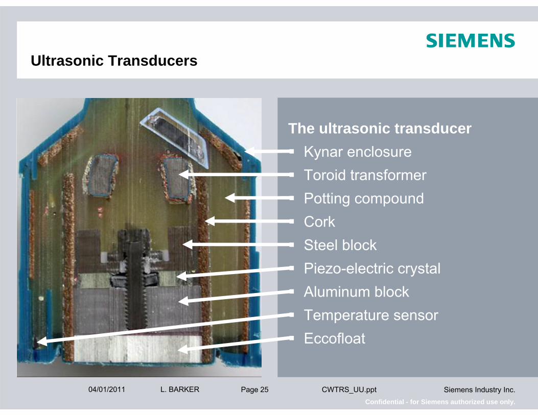
Ultrasonic Transducers
The ultrasonic transducerKynar enclosureToroid transformerPotting compoundCorkSteel blockPiezo-electric crystalAluminum blockTemperature sensorEccofloat

Page 2604/01/2011 Siemens Industry Inc.Confidential - for Siemens authorized use only.
L. BARKER CWTRS_UU.ppt
Ultrasonic Transducers
The ultrasonic transducerThe primary active component for the transducer is the piezo-electric crystal that vibrates when subjected to alternating voltageWhen voltage is removed the vibration begins to decay

Page 2704/01/2011 Siemens Industry Inc.Confidential - for Siemens authorized use only.
L. BARKER CWTRS_UU.ppt
Ultrasonics: what is an echo profile?
Digitally generated picture of the reflected echo received by the transducer Stored by the transceiver for processing
Transmit Pulse ECHO

Page 2804/01/2011 Siemens Industry Inc.Confidential - for Siemens authorized use only.
L. BARKER CWTRS_UU.ppt
How it Works –Sonic Intelligence and Ultrasonic Echo Profiles
1. The Pulse
2. The Return Signal

Page 2904/01/2011 Siemens Industry Inc.Confidential - for Siemens authorized use only.
L. BARKER CWTRS_UU.ppt
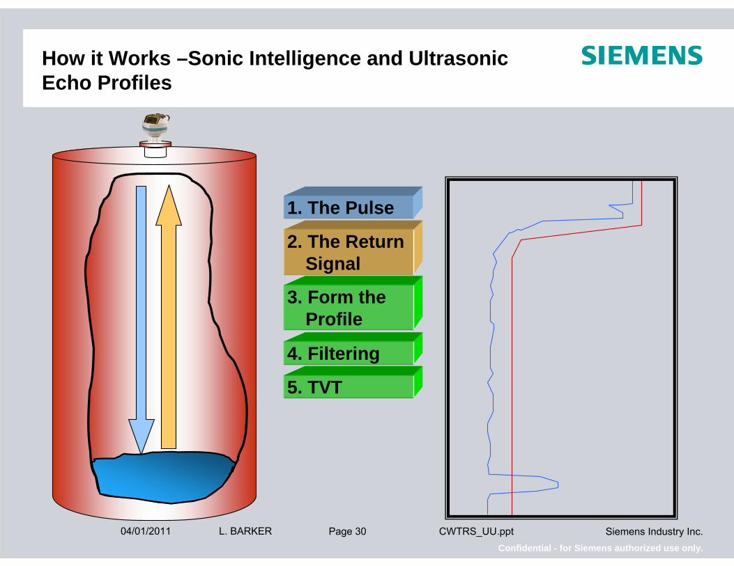
How it Works –Sonic Intelligence and Ultrasonic Echo Profiles
1. The Pulse
2. The Return Signal
3. Form the Profile
Page 3004/01/2011 Siemens Industry Inc.Confidential - for Siemens authorized use only.
L. BARKER CWTRS_UU.ppt
How it Works –Sonic Intelligence and Ultrasonic Echo Profiles
1. The Pulse
2. The Return Signal
3. Form the Profile
4. Filtering
5. TVT

Page 3104/01/2011 Siemens Industry Inc.Confidential - for Siemens authorized use only.
L. BARKER CWTRS_UU.ppt
How it Works –Sonic Intelligence and Ultrasonic Echo Profiles
1. The Pulse
2. The Return Signal
3. Form the Profile
4. Filtering
5. TVT
6. Echo Algorithms
7. Echo Selection

Page 3204/01/2011 Siemens Industry Inc.Confidential - for Siemens authorized use only.
L. BARKER CWTRS_UU.ppt
Echo Ranging Theory
Echo profileThe receiver must remain off during the signal transmission and ringdownSince time is relative to distance, the ringdown time is commonly referred to as the blanking distance of the transducerThe return signal cause the crystal to begin vibrating againThis signal is sent to the receiver for processing
100dB
75dB
50dB
25dB
0dB0ft 5ft 10ft 15ft 20ft 25ft
Transmit ReturnPulse Signal
Page 3304/01/2011 Siemens Industry Inc.Confidential - for Siemens authorized use only.
L. BARKER CWTRS_UU.ppt
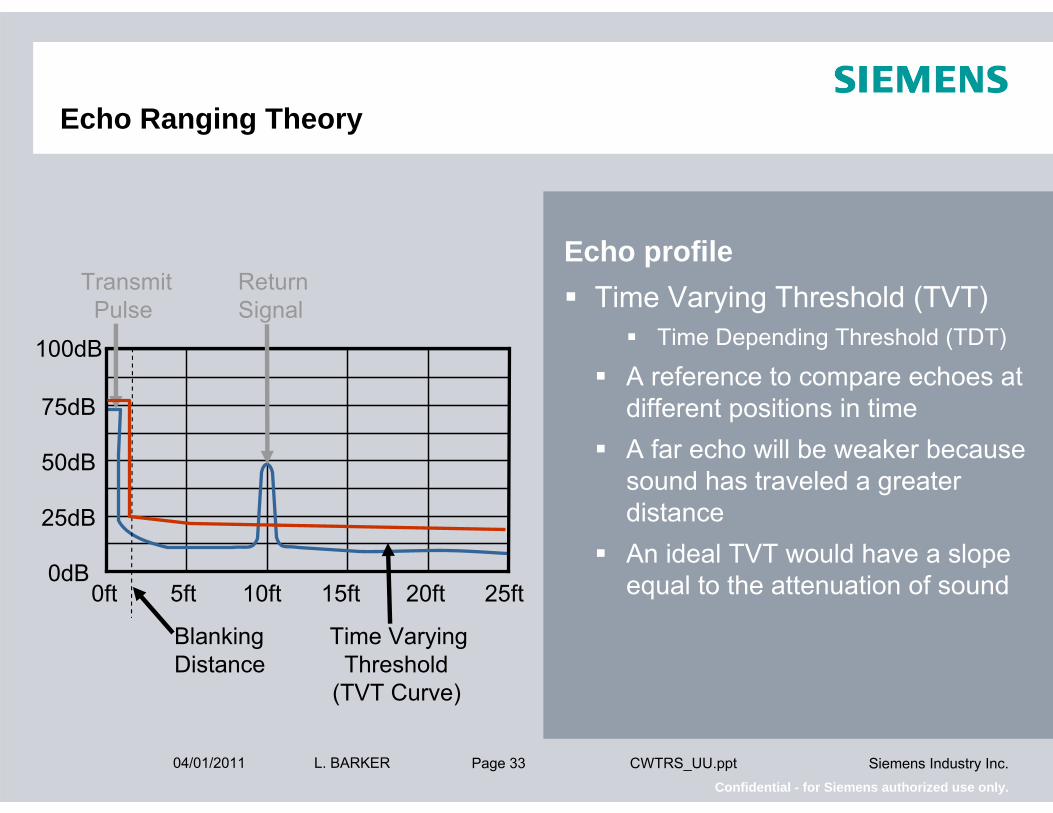
Echo Ranging Theory
Echo profileTime Varying Threshold (TVT)
Time Depending Threshold (TDT)
A reference to compare echoes at different positions in timeA far echo will be weaker because sound has traveled a greater distanceAn ideal TVT would have a slope equal to the attenuation of sound
100dB
75dB
50dB
25dB
0dB0ft 5ft 10ft 15ft 20ft 25ft
Transmit ReturnPulse Signal
Blanking Time VaryingDistance Threshold
(TVT Curve)

Page 3404/01/2011 Siemens Industry Inc.Confidential - for Siemens authorized use only.
L. BARKER CWTRS_UU.ppt
Echo Ranging Theory
Sonic IntelligenceEcho Lock Window
The width of the window is set by the measure response parameter Dampens false echoes outside of the windowRequires an echo outside the window to be present for five consecutive shots before it is considered a true echo
100dB
75dB
50dB
25dB
0dB0ft 5ft 10ft 15ft 20ft 25ft
Transmit Return Echo LockPulse Signal Window
Blanking Time VaryingDistance Threshold
(TVT Curve)

Page 3504/01/2011 Siemens Industry Inc.Confidential - for Siemens authorized use only.
L. BARKER CWTRS_UU.ppt
Echo Ranging Theory
Sonic IntelligenceEcho Lock
Uses a wide transmit pulse to provide a stronger return echo to detect more distant targetsThe echo lock window locks on to the selected echo in order to ignore spurious echoes from agitator blades or from random electrical interference
100dB
75dB
50dB
25dB
0dB0ft 5ft 10ft 15ft 20ft 25ft
Transmit Return Echo LockPulse Signal Window
Blanking Time VaryingDistance Threshold
(TVT Curve)

Page 3604/01/2011 Siemens Industry Inc.Confidential - for Siemens authorized use only.
L. BARKER CWTRS_UU.ppt
Echo Ranging Theory
Sonic IntelligenceSelecting the true material echo
Area – the measure the area of each echo
100dB
75dB
50dB
25dB
0dB0ft 5ft 10ft 15ft 20ft 25ft
Transmit Return Echo LockPulse Signal Window
Blanking Time VaryingDistance Threshold
(TVT Curve)

Page 3704/01/2011 Siemens Industry Inc.Confidential - for Siemens authorized use only.
L. BARKER CWTRS_UU.ppt
Echo Ranging Theory
Sonic IntelligenceSelecting the true material echo
Area – the measure the area of each echoLargest – the measure of the largest height of each echo
100dB
75dB
50dB
25dB
0dB0ft 5ft 10ft 15ft 20ft 25ft
Transmit Return Echo LockPulse Signal Window
Blanking Time VaryingDistance Threshold
(TVT Curve)

Page 3804/01/2011 Siemens Industry Inc.Confidential - for Siemens authorized use only.
L. BARKER CWTRS_UU.ppt
Echo Ranging Theory
Sonic IntelligenceSelecting the true material echo
Area – the measure the area of each echoLargest – the measure of the largest height of each echoFirst – the measure of the first significant echo
100dB
75dB
50dB
25dB
0dB0ft 5ft 10ft 15ft 20ft 25ft
Transmit Return Echo LockPulse Signal Window
Blanking Time VaryingDistance Threshold
(TVT Curve)

Page 3904/01/2011 Siemens Industry Inc.Confidential - for Siemens authorized use only.
L. BARKER CWTRS_UU.ppt
Echo Ranging Theory
Sonic IntelligenceScoring each echo
Area – the measure the area of each echoLargest – the measure of the largest height of each echoFirst – the measure of the first significant echo
100dB
75dB
50dB
25dB
0dB0ft 5ft 10ft 15ft 20ft 25ft
Area
Largest
First

Page 4004/01/2011 Siemens Industry Inc.Confidential - for Siemens authorized use only.
L. BARKER CWTRS_UU.ppt
Echo Ranging Theory
Sonic IntelligenceScoring each echo
Scores are calculated and addedThe net Confidence is the value of the chosen echo minus the value of the next most significant echoTotal
Net Confidence
Area
Largest
First

Page 4104/01/2011 Siemens Industry Inc.Confidential - for Siemens authorized use only.
L. BARKER CWTRS_UU.ppt
Echo Ranging Theory
Auto False Echo SuppressionTypical profile of an obstruction error
An undesired echo can be ignored by lifting the TVT curve at the position of the false echoThis can be done manually or by performing Auto False Echo Suppression
100dB
75dB
50dB
25dB
0dB0ft 5ft 10ft 15ft 20ft 25ft
Obstruction TrueEcho
Blanking Time VaryingDistance Threshold
(TVT Curve)

Page 4204/01/2011 Siemens Industry Inc.Confidential - for Siemens authorized use only.
L. BARKER CWTRS_UU.ppt
Echo Ranging Theory
100dB
75dB
50dB
25dB
0dB0ft 5ft 10ft 15ft 20ft 25ft
Blanking Time VaryingDistance Threshold
(TVT Curve)
Obstruction TrueEcho
Auto False Echo SuppressionTypical profile of an obstruction error
An undesired echo can be ignored by lifting the TVT curve at the position of the false echoThis can be done manually or by performing Auto False Echo Suppression

Page 4304/01/2011 Siemens Industry Inc.Confidential - for Siemens authorized use only.
L. BARKER CWTRS_UU.ppt
Process Intelligence
Signal profileTime Varying Threshold (TVT)
Process turbulentBuild-up on obstructions creates larger false echoes
Time
Amplitude

Page 4404/01/2011 Siemens Industry Inc.Confidential - for Siemens authorized use only.
L. BARKER CWTRS_UU.ppt
Process Intelligence
100dB
75dB
50dB
25dB
0dB0ft 5ft 10ft 15ft 20ft 25ft
Transmit False ReturnPulse Echoes Signal
Near Time VaryingRange Threshold
(TVT Curve)
Signal profileTime Varying Threshold (TVT)
Process turbulentBuild-up on obstructions creates larger false echoes

Page 4504/01/2011 Siemens Industry Inc.Confidential - for Siemens authorized use only.
L. BARKER CWTRS_UU.ppt
Process Intelligence
Signal profileTime Varying Threshold (TVT)
Process turbulentBuild-up on obstructions creates larger false echoes Increases overall signalTVT is high
Lower sensitivity
AdvantageNo need to remap
100dB
75dB
50dB
25dB
0dB0ft 5ft 10ft 15ft 20ft 25ft
Transmit False ReturnPulse Echoes Signal
Near Time VaryingRange Threshold
(TVT Curve)

Page 4604/01/2011 Siemens Industry Inc.Confidential - for Siemens authorized use only.
L. BARKER CWTRS_UU.ppt
Process Intelligence
Signal profileThe receiver must remain off during the signal transmission Referred to as the near range
100dB
75dB
50dB
25dB
0dB0ft 5ft 10ft 15ft 20ft 25ft
Transmit False ReturnPulse Echoes Signal

Page 4704/01/2011 Siemens Industry Inc.Confidential - for Siemens authorized use only.
L. BARKER CWTRS_UU.ppt
Process Intelligence
Signal profileTime Varying Threshold (TVT)
Process normalStrong signalTVT is high
Low sensitivity
Advantages False echoes not detectedNo mapping required
100dB
75dB
50dB
25dB
0dB0ft 5ft 10ft 15ft 20ft 25ft
Transmit False ReturnPulse Echoes Signal
Near Time VaryingRange Threshold
(TVT Curve)

Page 4804/01/2011 Siemens Industry Inc.Confidential - for Siemens authorized use only.
L. BARKER CWTRS_UU.ppt
Process Intelligence
AlgorithmsSelecting the true material echo
100dB
75dB
50dB
25dB
0dB0ft 5ft 10ft 15ft 20ft 25ft
Transmit Return Pulse Signal
Near Time VaryingRange Threshold
(TVT Curve)

Page 4904/01/2011 Siemens Industry Inc.Confidential - for Siemens authorized use only.
L. BARKER CWTRS_UU.ppt
The Anatomy of an Echo Profile
TVT – Time Varying Threshold
Confidence Marker
Echo Lock Window
Material Echo (true echo)
Noise Floor
Echo Profile(Blue line)
Indirect Echoes
Ring Down

Page 5004/01/2011 Siemens Industry Inc.Confidential - for Siemens authorized use only.
L. BARKER CWTRS_UU.ppt
Basic definitions – An Overview
Transmit Pulse (Produced Sound) The sound pulse that is generated by the ultrasonic transducer. Measured in decibels.
Ring DownThe time is takes for the transducer to stop vibrating after generating a pulse.
Product / Material EchoEcho received from product surface. Measured in decibels.
Noise Floor Spikes and/or general interference shown in echo profile. Generally displayed as less than
the ring down and material echo in amplitude (echo height)TVT (Time Varying Threshold)
Threshold set by the transceiver to assist in the selection of the correct echo. Shown as a red line. Any echo above this line is considered as a valid echo.

Page 5104/01/2011 Siemens Industry Inc.Confidential - for Siemens authorized use only.
L. BARKER CWTRS_UU.ppt
Basic definitions
A word about the Dynamic TVTAs stated on the previous slide the TVT line is set using advanced mathematical calculations. These calculations are continually updated using the information derived from the product echo and the noise floor.
As the noise floor rises the TVT line rises
As the noise floor lowers the TVT line lowers

This document includes confidential data that shall not be duplicated, used, distributed, or disclosed for any purpose unless authorized by Siemens.
Echo Ranging Theory questions?

This document includes confidential data that shall not be duplicated, used, distributed, or disclosed for any purpose unless authorized by Siemens.
SIEMENS Process Sensors Certified Integrators Training
This document includes confidential data that shall not be duplicated, used, distributed, or disclosed for any purpose unless authorized by Siemens.
Troubleshooting

Page 5404/01/2011 Siemens Industry Inc.Confidential - for Siemens authorized use only.
L. BARKER CWTRS_UU.ppt
Troubleshooting
Troubleshooting parametersEcho confidenceSignal strengthNoise level
Other important parametersCalibration Parameters Algorithm Parameter

Page 5504/01/2011 Siemens Industry Inc.Confidential - for Siemens authorized use only.
L. BARKER CWTRS_UU.ppt
Understanding Ultrasonics
Echo with Low Noise / High Echo Strength / High Echo Conf.Echo Confidence is an approximation of Product Echo minus NoiseThis is an example of a good application with no process or wiring issues
Noise
Echo Strength
Echo Conf.

Page 5604/01/2011 Siemens Industry Inc.Confidential - for Siemens authorized use only.
L. BARKER CWTRS_UU.ppt
Understanding Ultrasonics
Low Product Echo Strength / Low Echo Confidence / Low NoiseNoise level remains constant but Echo Strength and Echo Confidence go
downTypical causes: Poor aiming, foam, under-powered transducer, high dust, heavy steam, or material on face of the transducer
Noise Echo Strength
Echo Conf.

Page 5704/01/2011 Siemens Industry Inc.Confidential - for Siemens authorized use only.
L. BARKER CWTRS_UU.ppt
Understanding Ultrasonics
High Noise / High Echo Strength / Low Echo ConfidenceThe Echo Strength is constant but as Noise goes up the Echo Confidence goes downTypical cause is electrical or acoustical noise
Noise Echo Strength
Echo Conf

Page 5804/01/2011 Siemens Industry Inc.Confidential - for Siemens authorized use only.
L. BARKER CWTRS_UU.ppt
Primary readings are:Low echo conf Low echo strength Low noise
Understanding Ultrasonics
Cause: Improper aiming, presence of foam, under-powered transducer, high dust, sticky build-up on transducer face.
5:7101:5P807P806P805

Page 5904/01/2011 Siemens Industry Inc.Confidential - for Siemens authorized use only.
L. BARKER CWTRS_UU.ppt
Understanding Ultrasonics
Primary readings are:Low echo conf High echo strength Low noise
Cause: Over-powered transducer, or multiple echoes.
6:9731:8P807P806P805

Page 6004/01/2011 Siemens Industry Inc.Confidential - for Siemens authorized use only.
L. BARKER CWTRS_UU.ppt
Primary readings are: Low echo conf High echo strength High noise
Understanding Ultrasonics
VFD
P805 P807P8061:8
Cause: Electrical or Acoustical noise. Electrical source may be on transducer cable, power, or remote temperature sensor. Acoustical source may be from plant noise at the Ultrasonic Unit working frequency.
34:5560

Page 6104/01/2011 Siemens Industry Inc.Confidential - for Siemens authorized use only.
L. BARKER CWTRS_UU.ppt
Understanding Ultrasonics
Primary readings are:High echo conf High echo strength Low noise
Cause: Nothing. This is a good application. Time to go to the bar.
5:8591:25P807P806P805

Page 6204/01/2011 Siemens Industry Inc.Confidential - for Siemens authorized use only.
L. BARKER CWTRS_UU.ppt
68P 806
Troubleshooting
Signal StrentghParameter P806
Viewed in dBAn echo return is the first requirement for signal processingPoor echo strength is a result of weak echo returns and will result in poor confidence

Page 6304/01/2011 Siemens Industry Inc.Confidential - for Siemens authorized use only.
L. BARKER CWTRS_UU.ppt
17P 806
Troubleshooting
Signal StrentghPossible causes of a weak echo
Underpowered transducerPoor aimingHigh attenuation from extreme dust, steam or CO2
Surface may be poorly reflectiveTurbulentFoam

Page 6404/01/2011 Siemens Industry Inc.Confidential - for Siemens authorized use only.
L. BARKER CWTRS_UU.ppt
Troubleshooting
Echo return – troubleshootingCheck the calibration parametersCheck that the transducer face is perpendicular to the products angle of reposeRemove the transducer from the application and shoot against a solid target Temporarily install a spare transducer in the application
Use temporary wiring to eliminate wiring problems such as a faulty spice or water in conduit
Page 6504/01/2011 Siemens Industry Inc.Confidential - for Siemens authorized use only.
L. BARKER CWTRS_UU.ppt
Troubleshooting
Echo return – possible remediesVerify and correct the programming of the Quick Start Parameters Correct the aiming of the transducerReplace defective transducer Correct faulty wiring Replace defective wiring Use a higher powered transducerInstall a stilling well
Page 6604/01/2011 Siemens Industry Inc.Confidential - for Siemens authorized use only.
L. BARKER CWTRS_UU.ppt
45P 806
Troubleshooting
Summary – Troubleshooting Parameters
Signal strength - P806First requirement for signal processingTake steps to increase signal strengthRemember changing bin conditions will have an effect on signal strengthCompare to noise level to determine signal to noise ratio
23:43P 807
Page 6704/01/2011 Siemens Industry Inc.Confidential - for Siemens authorized use only.
L. BARKER CWTRS_UU.ppt
02:04P 807
Troubleshooting
Verify a noise problemParameter P807
Typical noise should be less than 5dB with the transducer disconnected
Page 6804/01/2011 Siemens Industry Inc.Confidential - for Siemens authorized use only.
L. BARKER CWTRS_UU.ppt
Troubleshooting
Determining the noise sourceStart by disconnecting the transducer from the transceiver
If the measured noise is above 5dB go to Non-Transducer Noise Sources
Page 6904/01/2011 Siemens Industry Inc.Confidential - for Siemens authorized use only.
L. BARKER CWTRS_UU.ppt
Troubleshooting
Non-transducer noise sourcesRemove all input and output cables from the controller individually while monitoring the noise
If the noise drops:Ensure low voltage cables are not being run adjacent to high voltage cables or near electrical noise generatorsEnsure correct wiring and proper grounding
If noise remains:Noise is either from the power source or it is being induced as EMFTry an alternative power sourceMove the controller away from the noise sourceShield the controller

Page 7004/01/2011 Siemens Industry Inc.Confidential - for Siemens authorized use only.
L. BARKER CWTRS_UU.ppt
Troubleshooting
Echo ConfidenceParameter P805
Signal to noise ratio is reflected in Echo ConfidenceHigh noise and/or weak echo strength will result in low confidenceThe first number is the Short Shot confidenceThe second number is the Long Shot confidence
0:18P 805

Page 7104/01/2011 Siemens Industry Inc.Confidential - for Siemens authorized use only.
L. BARKER CWTRS_UU.ppt
Troubleshooting
Sonic IntelligenceScoring each echo
Area – the measure the area of each echoLargest – the measure of the largest height of each echoFirst – the measure of the first significant echo
0ft 5ft 10ft 15ft 20ft 25ft
1st Echo A=8 L=20 F=20 Total=48
2nd Echo A=6 L=17 F=7 Total=30
Confidence = 48 – 30 = 18100dB
75dB
50dB
25dB
0dB

Page 7204/01/2011 Siemens Industry Inc.Confidential - for Siemens authorized use only.
L. BARKER CWTRS_UU.ppt
1st Echo F=25
2nd Echo F=0
Confidence = 25 – 0 = 25
Troubleshooting
Sonic IntelligenceAlgorithm parameter P820
Changing to single algorithm100dB
75dB
50dB
25dB
0dB0ft 5ft 10ft 15ft 20ft 25ft

Page 7304/01/2011 Siemens Industry Inc.Confidential - for Siemens authorized use only.
L. BARKER CWTRS_UU.ppt
Troubleshooting
Sonic IntelligenceTransducer ringing
The effects of ringing or obstructions in the blanking distanceRinging is typically caused by over tightening the transducerObstruction typically from nozzle or gradingIf P820 is set for “First echo” the obstruction will be selected as the true echo
100dB
75dB
50dB
25dB
0dB0ft 5ft 10ft 15ft 20ft 25ft
The effects of ringing

Page 7404/01/2011 Siemens Industry Inc.Confidential - for Siemens authorized use only.
L. BARKER CWTRS_UU.ppt
Troubleshooting
Sonic IntelligenceTransducer ringing
Extending the blanking zone, P800, the obstacle is ignored and the First Echo algorithm will select the material level as the first true echo
100dB
75dB
50dB
25dB
0dB0ft 5ft 10ft 15ft 20ft 25ft
Extended blanking distance – P800

Page 7504/01/2011 Siemens Industry Inc.Confidential - for Siemens authorized use only.
L. BARKER CWTRS_UU.ppt
Troubleshooting
Sonic IntelligenceUse caution when selecting a single algorithmOccasionally a single algorithm will give a low score to a true echo and a better score to a false echo Other algorithms will push up the total score of the correct echo and push down the total score of the false echoFor a given bin condition a single algorithm will give higher echo confidence, but as bin conditions change other algorithms may be requiredGenerally using all three algorithms provides more reliable operation over time

Page 7604/01/2011 Siemens Industry Inc.Confidential - for Siemens authorized use only.
L. BARKER CWTRS_UU.ppt
Troubleshooting
Summary – Troubleshooting Parameters
Confidence – P805If signal strength (P806) is strongAnd noise (P807) is lowAnd the resulting confidence (P805) remains low, you have multiple echoes
0ft 5ft 10ft 15ft 20ft 25ft
1st Echo A=8 L=20 F=20 Total=48
2nd Echo A=6 L=17 F=7 Total=30
Confidence = 48 – 30 = 18100dB
75dB
50dB
25dB
0dB

Page 7704/01/2011 Siemens Industry Inc.Confidential - for Siemens authorized use only.
L. BARKER CWTRS_UU.ppt
Troubleshooting
New installationsMost problems are:
Wiring errorsVerify wiring against schematicsFollow proper grounding proceduresUse grounded metal conduit
Installation errorsEnsure mounting to factory specificationsProtect from noise sourcesUse grounded metal conduit
Programming errorsPerform P999 factory resetProgram Quick Start Parameters – P001 thru P007Check for proper level reading before proceeding

Page 7804/01/2011 Siemens Industry Inc.Confidential - for Siemens authorized use only.
L. BARKER CWTRS_UU.ppt
Troubleshooting
Old installationsWhat has changed since start-up?
Has the noise level increased?New equipment, new VFD?
Has the echo strength decreased?Transducer aiming?Foamy surface?Water in conduit?
Have the parameters changed?Has someone altered the settings?

This document includes confidential data that shall not be duplicated, used, distributed, or disclosed for any purpose unless authorized by Siemens.
Troubleshooting questions?

This document includes confidential data that shall not be duplicated, used, distributed, or disclosed for any purpose unless authorized by Siemens.
Ultrasonic Mounting Considerations

Page 8104/01/2011 Siemens Industry Inc.Confidential - for Siemens authorized use only.
L. BARKER CWTRS_UU.ppt
Ladder Tank support braces
Fill pipe
Mounting Considerations
Mounting location
1 2 3 4

Page 8204/01/2011 Siemens Industry Inc.Confidential - for Siemens authorized use only.
L. BARKER CWTRS_UU.ppt
Mounting Considerations
Mounting location1. Too close to side wall –
interference from ladder rungs and support braces
1

Page 8304/01/2011 Siemens Industry Inc.Confidential - for Siemens authorized use only.
L. BARKER CWTRS_UU.ppt
Mounting Considerations
Mounting location1. Too close to side wall –
interference from ladder rungs and support braces
2. Correct installation – 1/3 the distance from the side wall, no obstructions
2

Page 8404/01/2011 Siemens Industry Inc.Confidential - for Siemens authorized use only.
L. BARKER CWTRS_UU.ppt
Mounting Considerations
Mounting location1. Too close to side wall –
interference from ladder rungs and support braces
2. Correct installation – 1/3 the distance from the side wall, no obstructions
3. Center of a parabolic tank –problems with secondary echoes
3
-3dB (50%)

Page 8504/01/2011 Siemens Industry Inc.Confidential - for Siemens authorized use only.
L. BARKER CWTRS_UU.ppt
Mounting Considerations
Mounting location1. Too close to side wall –
interference from ladder rungs and support braces
2. Correct installation – 1/3 the distance from the side wall, no obstructions
3. Center of a parabolic tank –problems with secondary echoes
3

Page 8604/01/2011 Siemens Industry Inc.Confidential - for Siemens authorized use only.
L. BARKER CWTRS_UU.ppt
Mounting Considerations
Mounting location1. Too close to side wall –
interference from ladder rungs and support braces
2. Correct installation – 1/3 the distance from the side wall, no obstructions
3. Center of a parabolic tank –problems with secondary echoes
4. Obstruction from fill stream
4
Page 8704/01/2011 Siemens Industry Inc.Confidential - for Siemens authorized use only.
L. BARKER CWTRS_UU.ppt
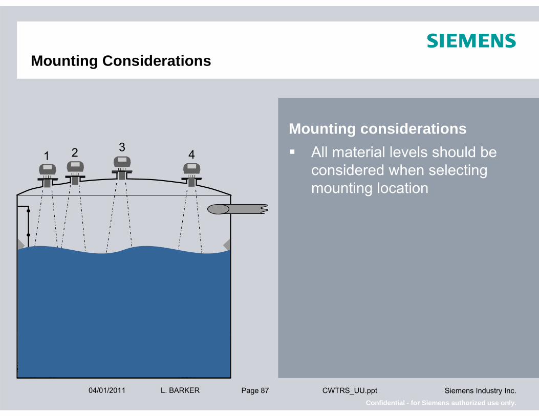
Mounting Considerations
Mounting considerationsAll material levels should be considered when selecting mounting location
42 31

Page 8804/01/2011 Siemens Industry Inc.Confidential - for Siemens authorized use only.
L. BARKER CWTRS_UU.ppt
Mounting Considerations
Mounting considerationsAll material levels should be considered when selecting mounting locationIf forced to mount close to side wall obstructions must be exposed before Auto False Echo Suppression can be performed
1

Page 8904/01/2011 Siemens Industry Inc.Confidential - for Siemens authorized use only.
L. BARKER CWTRS_UU.ppt
Mounting Considerations
Mounting considerationsAll material levels should be considered when selecting mounting locationIf forced to mount close to side wall obstructions must be exposed before Auto False Echo Suppression can be performedIt is preferred to perform Auto False Echo Suppression with the vessel empty
Careful not to map the bottom of the vessel!
1
Page 9004/01/2011 Siemens Industry Inc.Confidential - for Siemens authorized use only.
L. BARKER CWTRS_UU.ppt
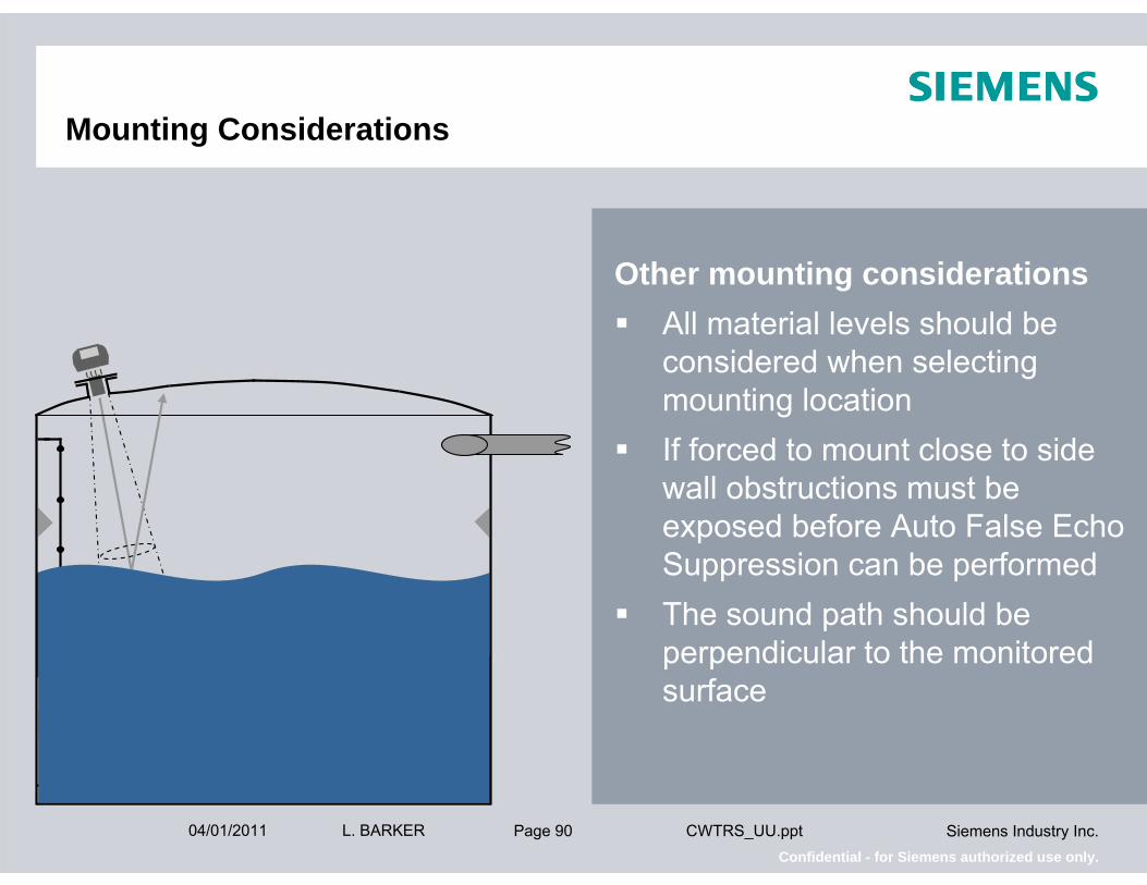
Mounting Considerations
Other mounting considerationsAll material levels should be considered when selecting mounting locationIf forced to mount close to side wall obstructions must be exposed before Auto False Echo Suppression can be performedThe sound path should be perpendicular to the monitored surface
Page 9104/01/2011 Siemens Industry Inc.Confidential - for Siemens authorized use only.
L. BARKER CWTRS_UU.ppt
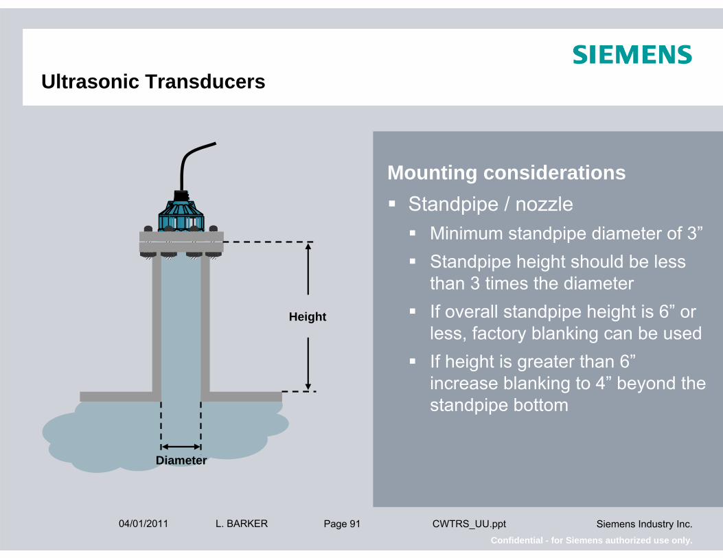
Ultrasonic Transducers
Mounting considerationsStandpipe / nozzle
Minimum standpipe diameter of 3”Standpipe height should be less than 3 times the diameterIf overall standpipe height is 6” or less, factory blanking can be usedIf height is greater than 6”increase blanking to 4” beyond the standpipe bottom
Height
Diameter

Page 9204/01/2011 Siemens Industry Inc.Confidential - for Siemens authorized use only.
L. BARKER CWTRS_UU.ppt
Ultrasonic Transducers
Mounting considerationsStandpipe / nozzle
When considering height to width ratio ensure standpipe inside the vessel in included
Height
Diameter

Page 9304/01/2011 Siemens Industry Inc.Confidential - for Siemens authorized use only.
L. BARKER CWTRS_UU.ppt
Ultrasonic Transducers
Diameter
Height
Mounting considerationsStandpipe / nozzle
When considering height to width ratio ensure standpipe inside the vessel in includedIdeally, standpipe nozzles should be cut at a 45° angle

Page 9404/01/2011 Siemens Industry Inc.Confidential - for Siemens authorized use only.
L. BARKER CWTRS_UU.ppt
Ultrasonic Transducers
Height
Diameter
Mounting considerationsStandpipe / nozzle
When considering height to width ratio ensure standpipe inside the vessel in includedIdeally, standpipe nozzles should be cut at a 45° angleStandpipe side wall should be seamless and free of welds or burrs

Page 9504/01/2011 Siemens Industry Inc.Confidential - for Siemens authorized use only.
L. BARKER CWTRS_UU.ppt
Ultrasonic Transducers
Mounting considerationsStilling Well
Vessels with obstructionsFoamHighly agitated surfacesInstalled inside or outside the vesselMust be vented at top with inlet at the bottomClean liquids only

Page 9604/01/2011 Siemens Industry Inc.Confidential - for Siemens authorized use only.
L. BARKER CWTRS_UU.ppt
Ultrasonic Transducers
Mounting accessories – liquid applications
Bonded flanges for non-corrosive applications

Page 9704/01/2011 Siemens Industry Inc.Confidential - for Siemens authorized use only.
L. BARKER CWTRS_UU.ppt
Ultrasonic Transducers
Mounting accessories – liquid applications
Bonded flanges for non-corrosive applicationsTeflon faced flanges for corrosive applications

Page 9804/01/2011 Siemens Industry Inc.Confidential - for Siemens authorized use only.
L. BARKER CWTRS_UU.ppt
Ultrasonic Transducers
Mounting accessories – liquid applications
Bonded flanges for non-corrosive applicationsTeflon faced flanges for corrosive applicationsFlange adaptorSubmergence shield
Transducer with submergence shield, used in applications where flooding is possible
Submersible
Rigid metal conduit
Coupling
Submergence shield

This document includes confidential data that shall not be duplicated, used, distributed, or disclosed for any purpose unless authorized by Siemens.
SIEMENS Process Sensors Applications
This document includes confidential data that shall not be duplicated, used, distributed, or disclosed for any purpose unless authorized by Siemens.

Page 10004/01/2011 Siemens Industry Inc.Confidential - for Siemens authorized use only.
L. BARKER CWTRS_UU.ppt
Two Wire Loop Powered All in One Ultrasonic
SITRANS Probe LUTechnical specifications
ETFE or PVDF to suit chemical conditionsBlanking range – 10” (0.25m) to 40 ftAccuracy – .15% of rangeCommunications
HART standardProfibus PA option

Page 10104/01/2011 Siemens Industry Inc.Confidential - for Siemens authorized use only.
L. BARKER CWTRS_UU.ppt
Two Wire Loop Powered All in One Ultrasonic Unit
The new and extremely experienced SITRANS Probe LU
ApprovalsFM GeneralFM Class 1, Div. 2FM Intrinsically Safe (barrier required)

Page 10204/01/2011 Siemens Industry Inc.Confidential - for Siemens authorized use only.
L. BARKER CWTRS_UU.ppt
Remote Mounted Ultrasonic
Level only controllerLevel DistanceSpaceOne or three relays
Multifunctional controllerDifferentialVolume and pumped volumeOpen channel flowSix relays

Page 10304/01/2011 Siemens Industry Inc.Confidential - for Siemens authorized use only.
L. BARKER CWTRS_UU.ppt
Remote Mounted Ultrasonic
Key featuresLiquids or solids to 50ft (15m)SIMATIC PDM for configuration and diagnosticsOn board Modbus RS-232 / RS-485Field installable communications
Profibus DPAllen-Bradley Remote I/ODeviceNet

Page 10404/01/2011 Siemens Industry Inc.Confidential - for Siemens authorized use only.
L. BARKER CWTRS_UU.ppt
Remote Mounted Ultrasonic
Key featuresOutputs
One, three, or six relays Two mA outputs
Two transducer inputs (six relay version only)
Differential – dual point difference or dual point average Optional independent dual point measurement

Page 10504/01/2011 Siemens Industry Inc.Confidential - for Siemens authorized use only.
L. BARKER CWTRS_UU.ppt
Remote Mounted Ultrasonic
Key featuresInputs
Two discrete inputsOne analog signal input (six relay model only)

Page 10604/01/2011 Siemens Industry Inc.Confidential - for Siemens authorized use only.
L. BARKER CWTRS_UU.ppt
Remote Mounted Ultrasonic
Key featuresWall Cling Reduction
Set level set-point ON and level set-point offEnter a wall cling valuePump on and off levels will be a randomly selected within the Random Set-point Range
Level Set-point ON
Wall Cling Value
Level Set-point OFF
Random Set-point Range

Page 10704/01/2011 Siemens Industry Inc.Confidential - for Siemens authorized use only.
L. BARKER CWTRS_UU.ppt
Remote Mounted Ultrasonic
Optional key featureTwo transducer input
Differential – dual point difference or dual point average
Page 10804/01/2011 Siemens Industry Inc.Confidential - for Siemens authorized use only.
L. BARKER CWTRS_UU.ppt
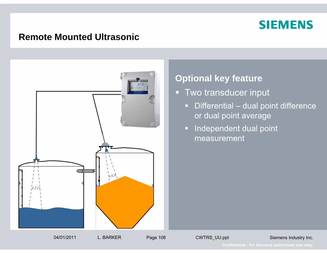
Remote Mounted Ultrasonic
Optional key featureTwo transducer input
Differential – dual point difference or dual point averageIndependent dual point measurement

Page 10904/01/2011 Siemens Industry Inc.Confidential - for Siemens authorized use only.
L. BARKER CWTRS_UU.ppt
Applications
Typical applicationsLift stations

Page 11004/01/2011 Siemens Industry Inc.Confidential - for Siemens authorized use only.
L. BARKER CWTRS_UU.ppt
Applications
Typical applicationsLift stationsOCM flow

Page 11104/01/2011 Siemens Industry Inc.Confidential - for Siemens authorized use only.
L. BARKER CWTRS_UU.ppt
Applications
Typical applicationsLift stationsOCM flowPump control

Page 11204/01/2011 Siemens Industry Inc.Confidential - for Siemens authorized use only.
L. BARKER CWTRS_UU.ppt
Applications
Typical applicationsLift stationsOCM flowPump controlClean water storage

Page 11304/01/2011 Siemens Industry Inc.Confidential - for Siemens authorized use only.
L. BARKER CWTRS_UU.ppt
Applications
Typical applicationsLift stationsOCM flowPump controlClean water storageBulk storage

Page 11404/01/2011 Siemens Industry Inc.Confidential - for Siemens authorized use only.
L. BARKER CWTRS_UU.ppt
Applications
Typical applicationsLift stationsOCM flowPump controlClean water storageBulk storageThe most widely used product in the Water & Waste Water industries

Page 11504/01/2011 Siemens Industry Inc.Confidential - for Siemens authorized use only.
L. BARKER CWTRS_UU.ppt
Contact Information
Mike GavanSr. Application Engineer / PS2 Product PromoterWest/Midwest Region
Cell: 972-672-4664E-Mail: [email protected]
www.siemens.com/level
This document includes confidential data that shall not be duplicated, used, distributed, or disclosed for any purpose unless authorized by Siemens.
Thank you for your attention!