Siemens Industry, Inc / IA / Process Instruments Level ... Measurement Products Basic Non-contacting...
35
Restricted © Siemens Industry, Inc. 2015 All rights reserved. Answers for industry. Level Measurement Products Basic Non-contacting Theories Siemens Industry, Inc / IA / Process Instruments
Transcript of Siemens Industry, Inc / IA / Process Instruments Level ... Measurement Products Basic Non-contacting...
Restricted © Siemens Industry, Inc. 2015 All rights reserved. Answers for industry.
Level Measurement Products Basic Non-contacting Theories
Siemens Industry, Inc / IA / Process Instruments

Restricted © Siemens Industry, Inc. 2014 All rights reserved.
Page 2 Klee / PI Process Instrumentation
Which sailboat is closest? How do you know?

Restricted © Siemens Industry, Inc. 2014 All rights reserved.
Page 3 Klee / PI Process Instrumentation
Now which sailboat is closest?

Restricted © Siemens Industry, Inc. 2014 All rights reserved.
Page 4 Klee / PI Process Instrumentation
Non-contacting Technologies Ultrasonics and Radar
Echo Ranging and Time of Flight

Restricted © Siemens Industry, Inc. 2014 All rights reserved.
Page 5 Klee / PI Process Instrumentation
Let’s take a look under the hood…

Restricted © Siemens Industry, Inc. 2014 All rights reserved.
Page 6 Klee / PI Process Instrumentation
Ultrasonic Level Echo Ranging and Time of Flight
Sound travels at constant known velocity at a given temperature
52.65 mS 28.11 mS 31.95 mS 35.22 mS 38.55 mS 45.18 mS 41.99 mS 49.00 mS 55.12 mS 0.00 mS 3.02 mS 6.10 mS 9.80 mS 12.30 mS 15.10 mS 16.07 mS 19.19 mS 25.77 mS 22.55 mS 58.20 mS

Restricted © Siemens Industry, Inc. 2014 All rights reserved.
Page 7 Klee / PI Process Instrumentation
Ultrasonic Level Echo Ranging Calculation
DISTANCE = VELOCITY x TIME
Speed of sound in air @68Fº is 1128ft/s
Time between sound
transmission and echo received
65.6 ft = 1128.6 ft/s x 58.2 mS
Divide by 2 to determine travel
distance one way 65.6 ÷ 2 = 32.8ft
Distance
Example: for a 58.2 millisecond time interval

Restricted © Siemens Industry, Inc. 2014 All rights reserved.
Page 8 Klee / PI Process Instrumentation
Radar Level Echo Ranging Calculation
DISTANCE = VELOCITY x TIME
Speed of light is 300,000,000
mps
Time between sound
transmission and echo received
20 m = 300,000,000 mps x 66.67 nS
Divide by 2 to determine travel time one way
20 ÷ 2 = 10m Distance
Example: for a 66.67 nanosecond time interval

Restricted © Siemens Industry, Inc. 2014 All rights reserved.
Page 9 Klee / PI Process Instrumentation
Level Space Distance
DIFFERENTIAL
Volume
FLOW
Siemens Non-contacting Level operations

Restricted © Siemens Industry, Inc. 2015 All rights reserved. Answers for industry.
Level Measurement Products Sonic and Process Intelligence
Siemens Industry, Inc / IA / Process Instruments

Restricted © Siemens Industry, Inc. 2014 All rights reserved.
Page 11 Klee / PI Process Instrumentation
Siemens Intelligence Sonic and Process Intelligence
Sonic and Process Intelligence.
Setting Siemens apart.

Restricted © Siemens Industry, Inc. 2014 All rights reserved.
Page 12 Klee / PI Process Instrumentation
Level reading example: If the empty distance is 50ft and distance measured by the device is 30ft then material level calculated is:
50ft – 30ft = 20ft
50ft
= 30ft
Transceiver or Transmitter
20ft
Level calculation from a distance measurement
OR OR
Known distance
Time of Flight The calculation of level

Restricted © Siemens Industry, Inc. 2014 All rights reserved.
Page 13 Klee / PI Process Instrumentation
What are sonic intelligence and process intelligence?
Sonic intelligence and process intelligence are embedded firmware that provide: • Fast and easy product set-up • Repeatable, accurate and reliable level detection • Flexibility
• Sonic intelligence is used in our Ultrasonic devices • Process intelligence is used in our radar devices

Restricted © Siemens Industry, Inc. 2014 All rights reserved.
Page 14 Klee / PI Process Instrumentation
Sonic and Process Intelligence for non-contacting level measurement
Non-contacting level measurement devices
Ultrasonic devices and Sonic Intelligence Radar devices and Process Intelligence
LUT400 SITRANS LU02 SITRANS LU10
HydroRanger MultiRanger
Probe LU Probe LR LR200
LR250/ LR260
LR560 LR460 The Probe

Restricted © Siemens Industry, Inc. 2014 All rights reserved.
Page 15 Klee / PI Process Instrumentation
What sets us apart?
Experience • Over 40 years and 1 million applications worth of real-world field experience.
Process Knowledge Our Time Varying Threshhold (TVT) is Dynamic Works in 95% of all applications right from Quick Start without any tuning Adjustable to the applications needs

Restricted © Siemens Industry, Inc. 2014 All rights reserved.
Page 17 Klee / PI Process Instrumentation
Siemens “Sonic & Process Intelligence” How it works – radar and ultrasonic echo profiles
1. The Pulse
2. The Return Signal
3. Form the Profile
4. Filtering
5. TVT
6. Echo Algorithms
7. Echo Selection

Restricted © Siemens Industry, Inc. 2014 All rights reserved.
Page 18 Klee / PI Process Instrumentation
Break . Be back in 15 minutes

Restricted © Siemens Industry, Inc. 2014 All rights reserved.
Page 19 Klee / PI Process Instrumentation
Changing Process Conditions
Siemens “Sonic & Process Intelligence”– Dynamic TVT

Restricted © Siemens Industry, Inc. 2014 All rights reserved.
Page 20 Klee / PI Process Instrumentation
Changes in process conditions directly impact the signal strength Foam, Steam, Agitation, Dust
Siemens “Sonic & Process Intelligence” – Dynamic TVT

Restricted © Siemens Industry, Inc. 2014 All rights reserved.
Page 21 Klee / PI Process Instrumentation
With a fixed threshold, as signal strength degrades, it is possible for the unit to lose sight of the material level entirely (Loss of Echo)
Changes in process conditions directly impact the signal strength Foam, Steam, Agitation, Dust
Siemens “Sonic & Process Intelligence” – Dynamic TVT

Restricted © Siemens Industry, Inc. 2014 All rights reserved.
Page 22 Klee / PI Process Instrumentation
With a fixed threshold, as signal strength degrades, it is possible for the unit to lose sight of the material level entirely (Loss of Echo)
Changes in process conditions directly impact the signal strength Foam, Steam, Agitation, Dust
Our dynamic TVT adjusts itself with each shot maintaining a lock on the material level as the signal strength decreases
Siemens “Sonic & Process Intelligence” – Dynamic TVT

Restricted © Siemens Industry, Inc. 2014 All rights reserved.
Page 23 Klee / PI Process Instrumentation
Siemens “Sonic & Process Intelligence” – Dynamic TVT and Foam
Low Frequency High Frequency
FOAM DENSE MEDIUM LIGHT

Restricted © Siemens Industry, Inc. 2014 All rights reserved.
Page 24 Klee / PI Process Instrumentation
Installation Challenges – Obstructions
Split silo with supports
Narrow Wetwell
Agitator Blades

Restricted © Siemens Industry, Inc. 2014 All rights reserved.
Page 25 Klee / PI Process Instrumentation
Echo Ranging Theory
Echo profile The receiver must remain off
during the signal transmission and ringdown
Since time is relative to distance, the ringdown time is commonly referred to as the blanking distance of the transducer
The return signal cause the crystal to begin vibrating again
This signal is sent to the receiver for processing
100dB
75dB
50dB
25dB
0dB
0ft 5ft 10ft 15ft 20ft 25ft
Transmit Return Pulse Signal

Restricted © Siemens Industry, Inc. 2014 All rights reserved.
Page 26 Klee / PI Process Instrumentation
Echo Ranging Theory
Echo profile Time Varying Threshold (TVT) A reference to compare echoes at
different positions in time A far echo will be weaker because
sound has traveled a greater distance
An ideal TVT would have a slope equal to the attenuation of sound
100dB
75dB
50dB
25dB
0dB
0ft 5ft 10ft 15ft 20ft 25ft
Blanking Time Varying Distance Threshold (TVT Curve)
Transmit Return Pulse Signal

Restricted © Siemens Industry, Inc. 2014 All rights reserved.
Page 27 Klee / PI Process Instrumentation
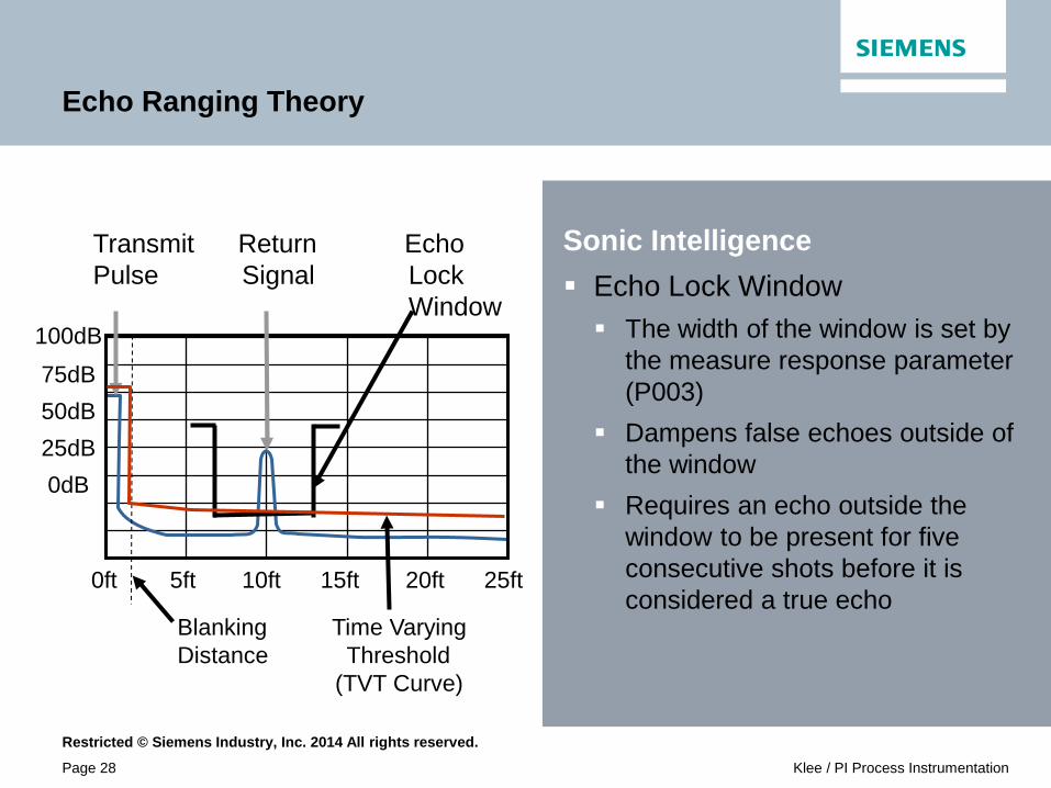
Echo Ranging Theory
Sonic Intelligence Echo Lock Window The width of the window is set by
the measure response parameter (P003)
Dampens false echoes outside of the window
Requires an echo outside the window to be present for five consecutive shots before it is considered a true echo
100dB
75dB
50dB
25dB
0dB
0ft 5ft 10ft 15ft 20ft 25ft
Blanking Time Varying Distance Threshold (TVT Curve)
Transmit Return Echo Pulse Signal Lock Window
Restricted © Siemens Industry, Inc. 2014 All rights reserved.
Page 28 Klee / PI Process Instrumentation
Echo Ranging Theory
Sonic Intelligence Echo Lock Window The width of the window is set by
the measure response parameter (P003)
Dampens false echoes outside of the window
Requires an echo outside the window to be present for five consecutive shots before it is considered a true echo
100dB
75dB
50dB
25dB
0dB
0ft 5ft 10ft 15ft 20ft 25ft
Blanking Time Varying Distance Threshold (TVT Curve)
Transmit Return Echo Pulse Signal Lock Window

Restricted © Siemens Industry, Inc. 2014 All rights reserved.
Page 29 Klee / PI Process Instrumentation
Echo Ranging Theory
Sonic Intelligence Echo Lock Window The width of the window is set by
the measure response parameter (P003)
Dampens false echoes outside of the window
Requires an echo outside the window to be present for five consecutive shots before it is considered a true echo
100dB
75dB
50dB
25dB
0dB
0ft 5ft 10ft 15ft 20ft 25ft
Blanking Time Varying Distance Threshold (TVT Curve)
Transmit Return Echo Pulse Signal Lock Window
Restricted © Siemens Industry, Inc. 2014 All rights reserved.
Page 30 Klee / PI Process Instrumentation
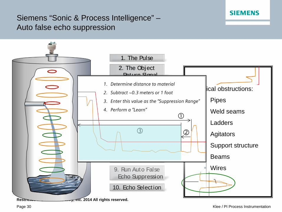
Siemens “Sonic & Process Intelligence” – Auto false echo suppression
1. The Pulse
2. The Object Return Signal
4. Form the Echo Profile
5. Apply Filtering
6. TVT Profile
7. Apply Echo Algorithms
10. Echo Selection
3. The Material Return Signal
8. Echo Selection
9. Run Auto False Echo Suppression
Typical obstructions:
Pipes
Weld seams
Ladders
Agitators
Support structure
Beams
Wires
1. Determine distance to material
2. Subtract ~0.3 meters or 1 foot
3. Enter this value as the “Suppression Range”
4. Perform a “Learn”
Restricted © Siemens Industry, Inc. 2014 All rights reserved.
Page 31 Klee / PI Process Instrumentation
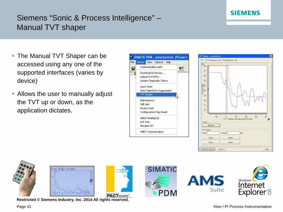
Siemens “Sonic & Process Intelligence” – Manual TVT shaper
The Manual TVT Shaper can be accessed using any one of the supported interfaces (varies by device)
Allows the user to manually adjust the TVT up or down, as the application dictates.

Restricted © Siemens Industry, Inc. 2014 All rights reserved.
Page 32 Klee / PI Process Instrumentation
Siemens “Sonic & Process Intelligence” – Multi-shot sampling/ number of shots
Preset number of shots varies from product to product
Increasing the shots improves confidence and reduces noise floor, however, it may also slow measurement reporting.

Restricted © Siemens Industry, Inc. 2014 All rights reserved.
Page 33 Klee / PI Process Instrumentation
Siemens “Sonic & Process Intelligence” – Filtering
Spike Filter
Narrow Echo Filter *Be careful when using the Narrow Echo Filter in liquids
applications as the true echo may be as narrow as the false echoes.
Narrow Echo Spikes

Restricted © Siemens Industry, Inc. 2014 All rights reserved.
Page 34 Klee / PI Process Instrumentation
Siemens “Sonic & Process Intelligence” – ALF algorithm
Echoes are evaluated by A, L, and F components (Area, Largest and First).
Scores/ confidences are assigned to each echo based on these 3 criteria
The highest score from the 3 criterion is selected for each echo.
The echo with the largest net score is selected as the true echo.
There are many variants of ALF, the most common being bLF (Best of Largest and First.
Only evaluates Largeness and Firstness – highest combined score wins

Restricted © Siemens Industry, Inc. 2014 All rights reserved.
Page 35 Klee / PI Process Instrumentation
Siemens “Sonic & Process Intelligence” – Quick start
For many of our products the quick start is a simple set of parameters needed to commission the unit.
Our Next Generation products use simple, Quick Start wizards locally at the unit, with the Hand Programmer, SIMATIC DTM or SIMATIC PDM.

Restricted © Siemens Industry, Inc. 2014 All rights reserved.
Page 36 Klee / PI Process Instrumentation
For Internal Use Only / © Siemens AG 2011. All rights reserved.
Thank You For Your Attention
Siemens Industry, Inc / IA / Process Instruments
Tim Bulbuk Siemens Application Engineer Siemens Process Instruments (517) 304-8018 [email protected]