Sidelobe Manipulation using Butler Matrix for 60 GHz ... · Sidelobe Manipulation using Butler...
12
Sidelobe Manipulation using Butler Matrix for 60 GHz Physical Layer Secure Wireless Communication Abstract-A means for scrambling the digital modulation content in the sidelobe of a wireless communication from a steerable antenna array is described. By exploiting the beam orthogonality characteristics associated with a Butler matrix, the concept of sidelobe manipulation is proposed. The method uses a Butler matrix parallel excited by an RF information data stream and artificial interference. The proposed system is implemented using a four by four Butler matrix MMIC and its operational characteristics are validated by bit error rate (BER) simulations for a 60 GHz QPSK transmission. The proposed architecture presented should find application in enhanced communication systems where security is of great concern. Comments on the PPT The slides 2-3 describe the characteristic of beam orthogonality in a Butler matrix driven antenna array. With the benefit of the beam orthogonality property, the arrangement of a system with sidelobe manipulation capability using a Buter matrix was proposed in slide 4. System performance simulation results presented in slides 5 and 6, in terms of the far-field patterns and constellation diagrams in IQ space, was performed under various scenarios, including different interference configurations and different receiver functionalities. The experimental validation based on a four by four Butler matrix designed for V- band operation via 0.35 μm SiGe bipolar process are provided in slides 7-9. From the bit error rate (BER) results we can observe that the randomly updated interference reduces the probability of decoding by both standard and advanced receivers along unselected directions, and thereby enhancing physical layer secrecy performance, with regards to BER beam-widths and maximum sidelobe levels.
Transcript of Sidelobe Manipulation using Butler Matrix for 60 GHz ... · Sidelobe Manipulation using Butler...

Sidelobe Manipulation using Butler Matrix for
60 GHz Physical Layer Secure Wireless
Communication
Abstract-A means for scrambling the digital modulation content in the sidelobe of
a wireless communication from a steerable antenna array is described. By
exploiting the beam orthogonality characteristics associated with a Butler matrix,
the concept of sidelobe manipulation is proposed. The method uses a Butler matrix
parallel excited by an RF information data stream and artificial interference. The
proposed system is implemented using a four by four Butler matrix MMIC and its
operational characteristics are validated by bit error rate (BER) simulations for a
60 GHz QPSK transmission. The proposed architecture presented should find
application in enhanced communication systems where security is of great concern.
Comments on the PPT
The slides 2-3 describe the characteristic of beam orthogonality in a Butler matrix
driven antenna array.
With the benefit of the beam orthogonality property, the arrangement of a system
with sidelobe manipulation capability using a Buter matrix was proposed in slide 4.
System performance simulation results presented in slides 5 and 6, in terms of the
far-field patterns and constellation diagrams in IQ space, was performed under
various scenarios, including different interference configurations and different
receiver functionalities.
The experimental validation based on a four by four Butler matrix designed for V-
band operation via 0.35 µm SiGe bipolar process are provided in slides 7-9. From
the bit error rate (BER) results we can observe that the randomly updated
interference reduces the probability of decoding by both standard and advanced
receivers along unselected directions, and thereby enhancing physical layer secrecy
performance, with regards to BER beam-widths and maximum sidelobe levels.

Author Bio
Yuan Ding received his Bachelor’s degree from Beihang University (BUAA), Beijing, China, in
2004 and received his Master’s degree from Tsinghua University, Beijing, China, in 2007, both in
Electronic Engineering.
He was a RF engineer in Motorola R&D center (Beijing, China) from 2007 to 2009, before
joining Freescale semiconductor Inc. (Beijing, China) as a RF field application engineer,
responsible for high power base-station amplifier design, from 2009 to 2011. He is currently
working toward his Ph.D. degree at the ECIT institute, Queen’s University of Belfast, Belfast,
United Kingdom. His research interests are in antenna array and physical layer security. He was the recipient of the
IET Best Student Paper award at LAPC 2013.
Vincent F. Fusco (S’82–M’82–SM’96–F’04) received the Bachelor’s degree (1st class honors) in
electrical and electronic engineering, the Ph.D. degree in microwave electronics, and the D.Sc.
degree, for his work on advanced front end architectures with enhanced functionality, from The
Queens University of Belfast (QUB), Belfast, Northern Ireland, in 1979, 1982, and 2000,
respectively.
He holds a personal chair in High Frequency Electronic Engineering at Queens University of
Belfast (QUB). His research interests include active antenna and front-end MMIC techniques. He is
head of the High Frequency Laboratories at QUB where he is also director of the International Centre for System on
Chip for Advanced Microwireless. Professor Fusco has published over 350 scientific papers in major journals and in
referred international conferences. He has authored two text books, holds patents related to self-tracking antennas
and has contributed invited papers and book chapters.
Prof. Fusco serves on the technical programme committee for various international conferences including the
European Microwave Conference. He is a Fellow of both the Institution of Engineering and Technology and the
Institute of Electrical and Electronic Engineers. In addition he is a Fellow of the Royal Academy of Engineers and a
member of the Royal Irish Academy. In 2012 he was awarded the IET Senior Achievement Award the Mountbatten
Medal.

Overview
September 2004
Sidelobe Manipulation using Butler Matrix
for 60 GHz Physical Layer Secure
Wireless Communication
Yuan Ding and Prof. Vincent Fusco

Beam orthogonality in a Butler matrix driven antenna array
The output signal vector A of an N by N Butler matrix can be obtained by
The excitation vector at the
input ports of the Butler matrix
1 11 12 1 1
2 21 22 2 2
1 2
N
N
N N N NN N
A T T T B
A T T T B
A T T T B
= = = ∗
L
L
M M M O M M
L
A T B
( )2 1 1
2 21
, 1,2, ,
N Nj m nN
mnT e m n N
N
π + + − − −
= ⋅ = L
Assume a 1-D half wavelength spaced antenna array with isotropic element radiation
pattern is connected at the output of the Butler matrix, the far-field pattern for
excitation Bn at the nth Butler matrix input port is
( )2 1 1 1
2 2 2
1
N N NN j m n j m cosNn
n
m
BE e e
N
ππ θ
θ
+ + + − − − − ⋅
=
= ⋅ ⋅
∑

Beam orthogonality in a Butler matrix driven antenna array
The maximum power spatial projection direction for each input port excitation is the
power null when other ports are excited. This is, sometimes, termed orthogonality in the
beam space.
0º 30º 60º 90º 120º 150º 180º
Spatial Direction θ
Magn
itud
e (
dB
)
−40
−30
−20
−10
0
Normalized radiation power patterns for each Butler matrix (4×4) input port excited
separatelyExcitation at the 1st input port
Excitation at the 2nd input port
Excitation at the 3rd input port
Excitation at the 4th input port
The main beam direction2 1
arccosn
n N
Nα
− − =
Similarly we can calculate Eq(θ) and αq for the excitation Bq at the qth Butler matrix input
port.
We can verify that En(αq) = 0 when n ≠ q, which indicates that the Eq(θ)’s main beam is
projected along the null radiation direction of En(θ). Ditto En(θ)’s main beam and Eq(θ)’s null
direction.
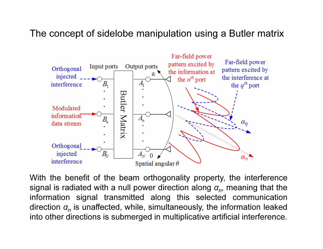
The concept of sidelobe manipulation using a Butler matrix
With the benefit of the beam orthogonality property, the interference
signal is radiated with a null power direction along αn, meaning that the
information signal transmitted along this selected communication
direction αnis unaffected, while, simultaneously, the information leaked
into other directions is submerged in multiplicative artificial interference.

Simulation results
Prerequisites:
� An ideal four by four Butler matrix with 1-D half wavelength spaced antenna array
connected at the output ports.
� Each array element has an isotropic radiation pattern.
� An information data stream modulated with QPSK is injected into the Butler matrix at the
second input port.
� The interference, injected into each remaining input port, is identical, and has a constant
magnitude of 10 dB lower than that of the information signal.
When the phase of the injected interference is constant, for example 60°, the far-field patterns
for each QPSK symbol transmitted are shown,
0º 30º 60º 90º 120º 150º 180º
Spatial Direction θ
Po
wer
(dB
)
−40
−30
−20
−10
0
3
104º 0º 30º 60º 90º 120º 150º 180º
Spatial Direction θ
Phase
0º
45º
90º
135º
180º
−45º
−90º
−135º
−180º 104º
Symbol ‘11’
Symbol ‘01’
Symbol ‘00’
Symbol ‘10’
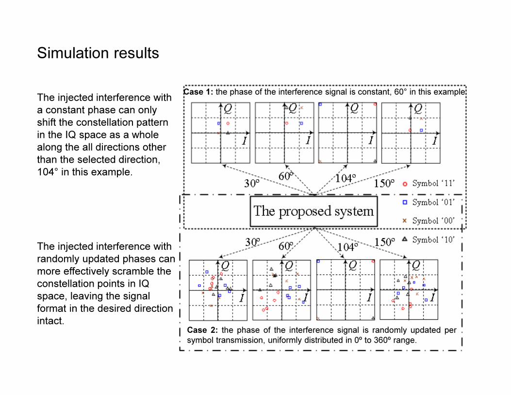
Simulation results
The injected interference with
a constant phase can only
shift the constellation pattern
in the IQ space as a whole
along the all directions other
than the selected direction,
104° in this example.
The injected interference with
randomly updated phases can
more effectively scramble the
constellation points in IQ
space, leaving the signal
format in the desired direction
intact.
Case 1: the phase of the interference signal is constant, 60° in this example
Case 2: the phase of the interference signal is randomly updated per
symbol transmission, uniformly distributed in 0º to 360º range.

Experimental validation at 60 GHz
The proposed system was validated using a four by four
Butler matrix designed for V-band operation via 0.35 µm
SiGe bipolar process.
0º 30º 60º 90º 120º 150º 180º
Spatial Direction θ
Po
wer
(dB
)
−40
−30
−20
−10
0
3
104º 0º 30º 60º 90º 120º 150º 180º
Spatial Direction θ
Phase
0º
45º
90º
135º
180º
−45º
−90º
−135º
−180º 104º
47º
135º
−43º
−135º
Symbol ‘11’
Symbol ‘01’
Symbol ‘00’
Symbol ‘10’
Based on the measured S-parameters of the Butler
matrix, when the phase of the injected interference is
constant, for example 60°, the far-field patterns for each
QPSK symbol transmitted are shown,

Experimental validation at 60 GHz
BER calculations:
0º 30º 60º 90º 120º 150º 180º
Spatial Direction θ
BER
10−1
10−2
10−3
10−4
10−5
100
3.4×10⁻⁵
104º
Standard QPSK receiver (QPSK): it decodes received noisy symbols based on which
quadrant the constellation points locate into.
More advanced receiver (APSK): it is able to detect the absolute magnitude and phase
of each received symbol. The advanced receiver allows ‘minimum Euclidean distance
decoding’.
A data stream with 106 random QPSK symbols is used, which allows BER down to 10−5
to be calculated
Information signal at the second input port and interference at
each remaining input ports. The phase of the interference is kept
constant, 60º.
−10 dB interference, QPSK receiver and SNR=12 dB
−10 dB interference, APSK receiver and SNR=12 dB
no interference and SNR=12 dB
−10 dB interference, QPSK receiver and SNR=20dB
−10 dB interference, APSK receiver and SNR=20 dB
no interference and SNR=20 dB

Experimental validation at 60 GHz
BER calculations:
0º 30º 60º 90º 120º 150º 180º
Spatial Direction θ
BER
10−1
10−2
10−3
10−4
10−5
100
104º 41º
Information at the
fourth input port
Information at the
second input port
BER spatial distributions for information signal at the second or the fourth input port and
interference at each remaining input ports. The phase of the interference is updated randomly.
SNR along information beam directions is set to 12 dB
−5 dB interference, QPSK and APSK receivers
−∞ dB interference
−10 dB interference, QPSK and APSK receivers
−5 dB interference, QPSK and APSK receivers
−10 dB interference, QPSK and APSK receivers
−∞ dB interference
Conclusion
By employing Butler matrix, a means for distorting the digital modulation
content in the sidelobes of a wireless communication was presented.
Injected artificial interference is projected along all spatial directions other
than the main information direction, and hence contaminates the leaked
information in such a fashion to prevent eavesdroppers from information
recovery through interception. It is also shown by extensive BER
simulations, based on the measured S-parameters of a Butler matrix
MMIC operating at 60 GHz, that dynamic random interference updating is
highly effective at returning high BER along unselected communication
directions. The approach suggested here opens the way for a new
means for securing Gigabit per second data transmissions associated
with V-Band short range communications while preserving beam
steering. The method is generally applicable to any radio communication
systems applying an orthogonal beam forming network.