Si1000/1/2/3/4/5 - Digi-Key Sheets/Silicon... · 2017-11-13 · 1 3 2 4 5

ColibrysSEISMIC
SI1000 – PRELIMINARY DATASHEET Single axis analog accelerometer
SI1000 is a high-end capacitive MEMS accelerometer specially designed for Strong Motion Class B seismic measurements.
Thanks to extremely low noise, low power, wide frequency response, small sized (LCC20) hermetically sealed package, SI1000 guarantees very accurate and stable seismic measurements, requiring neither recalibration nor maintenance during the lifecycle of the system.
Functional Block Diagram
Key features (typ.)
Ranges: +/-3, 5 g Non linearity : ±0.3% FS
Low Noise: 0.7 µg/√Hz (+/-3g) Size : <1cm2
Bandwidth: 0-550Hz (+/-3g) Embedded logic functions: Self-test, reset
Key Parameter, typical values SI1003 SI1005 Unit
Full-Scale acceleration ± 3 ± 5 g
White Noise 0.7 1.2 μg/√Hz
Noise (Integrated over 0.1Hz to 100Hz) 8 13 μg
Dynamic range (0.1Hz to 100Hz) 108.5 108.5 dB
Scale Factor Sensitivity 900 540 mV/g
Bandwidth (±3dB) 550 700 Hz
Operational temperature -40 to +85 -40 to +85 °C
Operating power consumption 90 90 mW
Size 9 x 9 9 x 9 mm2
Featured Applications (non-exhaustive):
Seismic Industrial Structural Health Monitoring of critical civil infrastructure (dams, bridges, buildings)
Low noise industrial measurements
High density urban monitoring networks
Safety systems

SI1000 – PRELIMINARY DATASHEET ColibrysSEISMIC
SAFR AN COLIBRYS S A 30S.SI1000. A.10.18
Av. des Sc iences 13 – 1400 Yverdon- les -Ba ins T +41 58 100 5000
www.saf ran-co l ib rys .com page 2 F +41 58 100 5001
SI1003 PARAMETERS All values are specified at ambient temperature (20°C) and at 3.3 V supply voltage VDD, unless otherwise stated. Acceleration values are defined for differential signal (OUTP-OUTN). Parameter Comments Min Typ. Max Unit
Accelerometer
Full scale ±3 g
White Noise In band 0.7 0.9 μg/√Hz
Noise Integrated over 0.1Hz to 100Hz 8 μg
Dynamic range for 100Hz bandwidth 108.5 dB
Non-Linearity IEEE Norm , % of full scale 0.3 1 %
Frequency response +3dB 450 550 Hz
Resonant frequency 1.0 kHz
Quality factor 10 a.u
Startup time Sensor operational, delay once POR triggered
20 µs
Bias (K0)
Nominal Calibration accuracy -10 10 mg
Temperature coefficient
Measured over [-40°C , 85°C] -0.3 0.3 mg/°C
Scale factor (K1)
Nominal Calibration accuracy 886 900 914 mV/g
Temperature coefficient
Measured over [-40°C , 85°C] 120 ppm/°C
Axis misalignment
Cross axis coupling -40 dB
-10 10 mrad
Self-test
Frequency 14 19 24 Hz
Duty cycle 50 %
Amplitude 0.25 g
Input threshold voltage 80 % VDD
Temperature sensor
Output voltage @20°C 1.20 1.23 1.26 V
Sensitivity -4.0 mV/°C
Output current load 10 μA
Output capacitive load 10 pF
Reset
Input threshold voltage active low 20 % VDD
Power requirements
Supply voltage (VDD) 3.2 3.3 3.4 V
Supply current (IDD) 22 27 32 mA
Accelerometer outputs
Output voltages OutP, OutN over full scale 0.14 3.16 V
Differential output Over full scale ±2.7 V
Resistive load 1000 kΩ
Capacitive load 100 pF
Table 1: SI1003 Specifications

SI1000 – PRELIMINARY DATASHEET ColibrysSEISMIC
SAFR AN COLIBRYS S A 30S.SI1000. A.10.18
Av. des Sc iences 13 – 1400 Yverdon- les -Ba ins T +41 58 100 5000
www.saf ran-co l ib rys .com page 3 F +41 58 100 5001
SI1005 PARAMETERS All values are specified at ambient temperature (20°C) and at 3.3 V supply voltage VDD, unless otherwise stated. Acceleration values are defined for differential signal (OUTP-OUTN). Parameter Comments Min Typ. Max Unit
Accelerometer
Full scale ±5 g
White Noise In band 1.2 1.5 μg/√Hz
Noise Integrated over 0.1Hz to 80Hz 13 μg
Dynamic range for 100Hz bandwidth 108.5 dB
Non-Linearity IEEE Norm , % of full scale 0.3 1 %
Frequency response +3dB 600 700 Hz
Resonant frequency 1.3 kHz
Quality factor 10 a.u
Startup time Sensor operational, delay once POR triggered
20 µs
Bias (K0)
Nominal Calibration accuracy -17 17 mg
Temperature coefficient
Measured over [-40°C , 85°C] -0.5 0.5 mg/°C
Scale factor (K1)
Nominal Calibration accuracy 531 540 549 mV/g
Temperature coefficient
Measured over [-40°C , 85°C] 120 ppm/°C
Axis misalignment
Cross axis coupling -40 dB
-10 10 mrad
Self-test
Frequency 14 19 24 Hz
Duty cycle 50 %
Amplitude 0.5 g
Input threshold voltage 80 % VDD
Temperature sensor
Output voltage @20°C 1.20 1.23 1.26 V
Sensitivity -4.0 mV/°C
Output current load 10 μA
Output capacitive load 10 pF
Reset
Input threshold voltage active low 20 % VDD
Power requirements
Supply voltage (VDD) 3.2 3.3 3.4 V
Supply current (IDD) 22 27 32 mA
Accelerometer outputs
Output voltages OutP, OutN over full scale 0.14 3.16 V
Differential output Over full scale ±2.7 V
Resistive load 1000 kΩ
Capacitive load 100 pF
Table 2: SI1005 Specifications

SI1000 – PRELIMINARY DATASHEET ColibrysSEISMIC
SAFR AN COLIBRYS S A 30S.SI1000. A.10.18
Av. des Sc iences 13 – 1400 Yverdon- les -Ba ins T +41 58 100 5000
www.saf ran-co l ib rys .com page 4 F +41 58 100 5001
Absolute maximum ratings Absolute maximum ratings are stresses ratings. Stresses above these ratings can cause permanent damage to the device. Exposure of the device to the absolute maximum ratings for an extended period may degrade the device and affect its reliability. Parameter Comments Min Typ Max Unit
Supply voltage (VDD) -0.3 +3.9 V
Voltage at any PIN -0.3 VDD +0.3 V
Operational temperature -40 85 °C
Storage temperature -55 125 °C
Vibration Random / 20-2’000Hz 20 g
Shock Single shocks / 0.15ms 1’500 g
ESD stress HBM model -1 1 kV
Table 3: Absolute maximum ratings

SI1000 – PRELIMINARY DATASHEET ColibrysSEISMIC
SAFR AN COLIBRYS S A 30S.SI1000. A.10.18
Av. des Sc iences 13 – 1400 Yverdon- les -Ba ins T +41 58 100 5000
www.saf ran-co l ib rys .com page 5 F +41 58 100 5001
Typical performances characteristics SI1003: Typical initial performances on multiple sensors at 3.3 VDC supply voltage (VDD) and ambient
temperature for all graphs, unless otherwise stated (multiple sensors: multiple color line / min-max: red line / typical value: green line).
Figure 1: Differential acceleration output
(OUTP-OUTN) at full scale Figure 2: Non-Linearity IEEE
Figure 3: Frequency response Figure 4: Noise Spectrum
Figure 5: Bias over temperature Figure 6: Scale Factor over temperature
SI1000 – PRELIMINARY DATASHEET ColibrysSEISMIC
SAFR AN COLIBRYS S A 30S.SI1000. A.10.18
Av. des Sc iences 13 – 1400 Yverdon- les -Ba ins T +41 58 100 5000
www.saf ran-co l ib rys .com page 6 F +41 58 100 5001
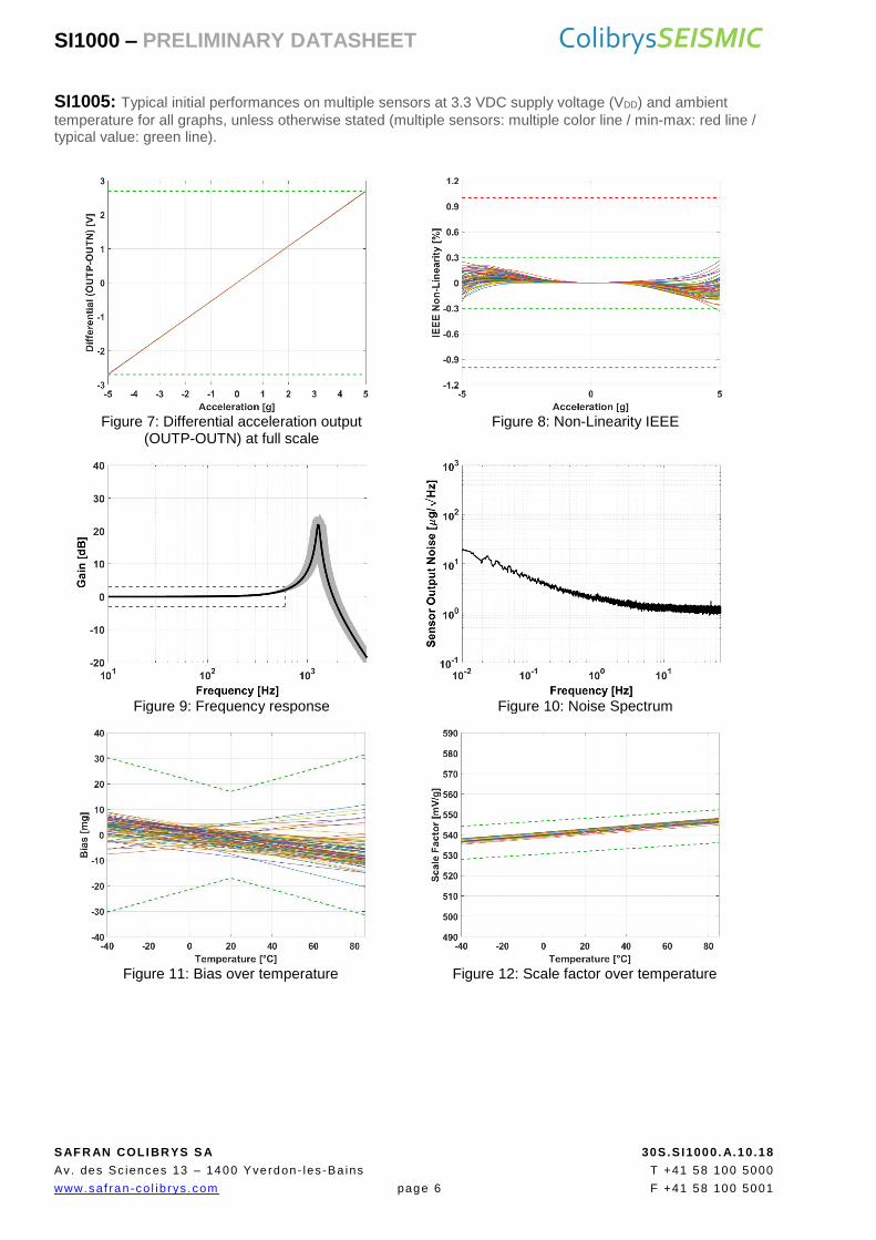
SI1005: Typical initial performances on multiple sensors at 3.3 VDC supply voltage (VDD) and ambient
temperature for all graphs, unless otherwise stated (multiple sensors: multiple color line / min-max: red line / typical value: green line).
Figure 7: Differential acceleration output
(OUTP-OUTN) at full scale Figure 8: Non-Linearity IEEE
Figure 9: Frequency response Figure 10: Noise Spectrum
Figure 11: Bias over temperature Figure 12: Scale factor over temperature
SI1000 – PRELIMINARY DATASHEET ColibrysSEISMIC
SAFR AN COLIBRYS S A 30S.SI1000. A.10.18
Av. des Sc iences 13 – 1400 Yverdon- les -Ba ins T +41 58 100 5000
www.saf ran-co l ib rys .com page 7 F +41 58 100 5001
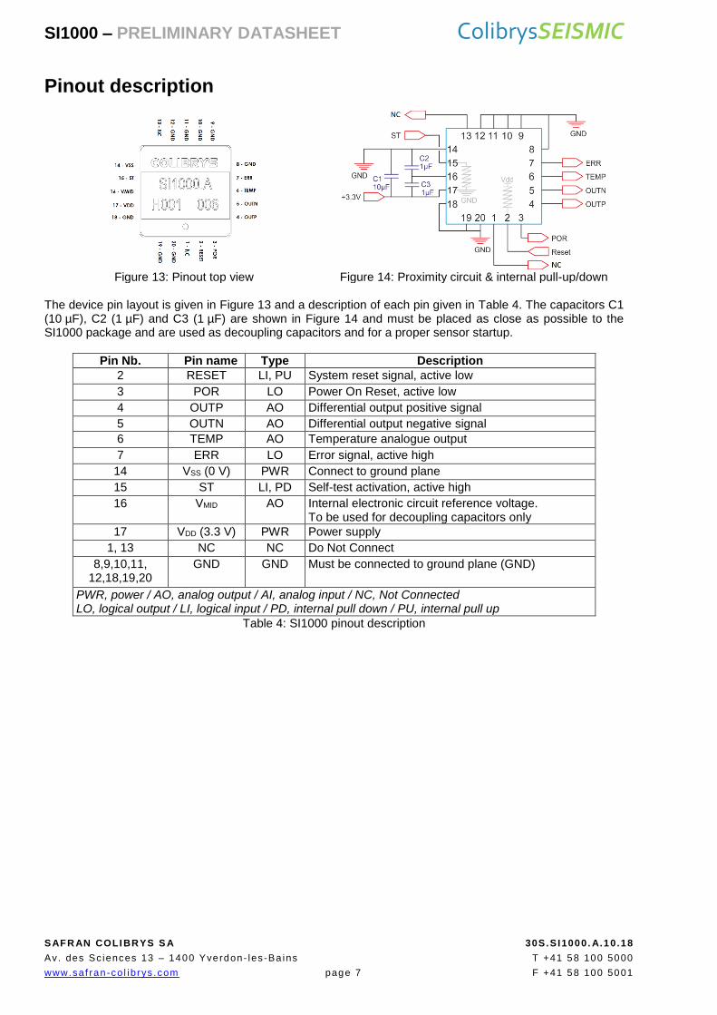
Pinout description
Figure 13: Pinout top view Figure 14: Proximity circuit & internal pull-up/down
The device pin layout is given in Figure 13 and a description of each pin given in Table 4. The capacitors C1 (10 µF), C2 (1 µF) and C3 (1 µF) are shown in Figure 14 and must be placed as close as possible to the SI1000 package and are used as decoupling capacitors and for a proper sensor startup.
Pin Nb. Pin name Type Description
2 RESET LI, PU System reset signal, active low
3 POR LO Power On Reset, active low
4 OUTP AO Differential output positive signal
5 OUTN AO Differential output negative signal
6 TEMP AO Temperature analogue output
7 ERR LO Error signal, active high
14 VSS (0 V) PWR Connect to ground plane
15 ST LI, PD Self-test activation, active high
16 VMID AO Internal electronic circuit reference voltage. To be used for decoupling capacitors only
17 VDD (3.3 V) PWR Power supply
1, 13 NC NC Do Not Connect
8,9,10,11, 12,18,19,20
GND GND Must be connected to ground plane (GND)
PWR, power / AO, analog output / AI, analog input / NC, Not Connected LO, logical output / LI, logical input / PD, internal pull down / PU, internal pull up
Table 4: SI1000 pinout description
SI1000 – PRELIMINARY DATASHEET ColibrysSEISMIC
SAFR AN COLIBRYS S A 30S.SI1000. A.10.18
Av. des Sc iences 13 – 1400 Yverdon- les -Ba ins T +41 58 100 5000
www.saf ran-co l ib rys .com page 8 F +41 58 100 5001
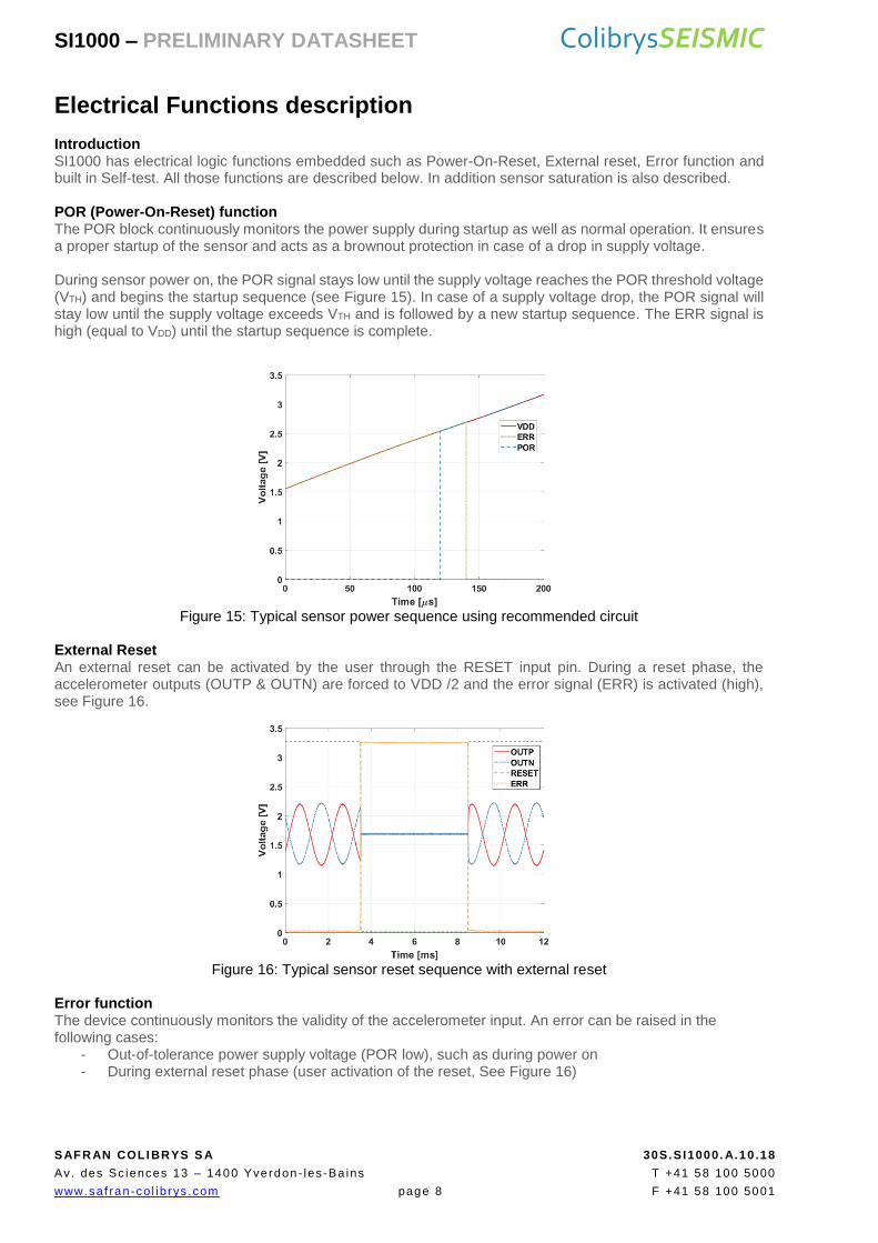
Electrical Functions description Introduction SI1000 has electrical logic functions embedded such as Power-On-Reset, External reset, Error function and built in Self-test. All those functions are described below. In addition sensor saturation is also described. POR (Power-On-Reset) function The POR block continuously monitors the power supply during startup as well as normal operation. It ensures a proper startup of the sensor and acts as a brownout protection in case of a drop in supply voltage. During sensor power on, the POR signal stays low until the supply voltage reaches the POR threshold voltage (VTH) and begins the startup sequence (see Figure 15). In case of a supply voltage drop, the POR signal will stay low until the supply voltage exceeds VTH and is followed by a new startup sequence. The ERR signal is high (equal to VDD) until the startup sequence is complete.
Figure 15: Typical sensor power sequence using recommended circuit
External Reset An external reset can be activated by the user through the RESET input pin. During a reset phase, the accelerometer outputs (OUTP & OUTN) are forced to VDD /2 and the error signal (ERR) is activated (high), see Figure 16.
Figure 16: Typical sensor reset sequence with external reset
Error function The device continuously monitors the validity of the accelerometer input. An error can be raised in the following cases:
- Out-of-tolerance power supply voltage (POR low), such as during power on - During external reset phase (user activation of the reset, See Figure 16)

SI1000 – PRELIMINARY DATASHEET ColibrysSEISMIC
SAFR AN COLIBRYS S A 30S.SI1000. A.10.18
Av. des Sc iences 13 – 1400 Yverdon- les -Ba ins T +41 58 100 5000
www.saf ran-co l ib rys .com page 9 F +41 58 100 5001
Built-in Self-Test function The built-in Self-Test mode generates a square wave signal on the device outputs (OUTP & OUTN) and can be used for device failure detection (see Figure 17). When activated, it induces an alternating electrostatic force on the mechanical sensing element and emulates an input acceleration at a defined frequency. This electrostatic force is in addition to any inertial acceleration acting on the sensor during self-test; therefore it is recommended to use the self-test function under quiescent conditions.
Figure 17: Built-in Self-Test signal on the differential acceleration output (f≈19Hz; a≈±0.25g)
Sensor Saturation Upon a high-amplitude acceleration input, the sensor saturates around 1.2 times its full scale acceleration. This behavior is illustrated in the figures below:
- The sensor detects acceleration up to its saturation. - When saturation ends, the sensor returns to nominal acceleration sensing.
Figure 18: 3g Sensor behavior under 6g sine Figure 19: 5g Sensor response to 11g sine
Figure 20: SI1003 versus reference sensor Figure 21: SI1005 versus reference sensor

SI1000 – PRELIMINARY DATASHEET ColibrysSEISMIC
SAFR AN COLIBRYS S A 30S.SI1000. A.10.18
Av. des Sc iences 13 – 1400 Yverdon- les -Ba ins T +41 58 100 5000
www.saf ran-co l ib rys .com page 10 F +41 58 100 5001
Dimensions and package specifications
The outline of the LCC20 ceramic package and the Center of Gravity ( ) is illustrated in the Figure 22.
Figure 22: Package mechanical dimension. Units are mm [inch]
Parameter Comments Min Typ Max Unit
Lead finishing Au plating Ni plating W (tungsten)
0.5 1.27 10
4
1.5 8.89 15
µm µm µm
Hermeticity According to MIL-STD-833-G 5·10-8 atm·cm3/s
Weight 1.5 grams
Size X Y Z
8.9 8.9 3.23
9.2 9.2 3.5
mm mm mm
Packaging RoHS compliant part. Nonmagnetic, LCC20 pin housing.
Proximity effect The sensor is sensitive to external parasitic capacitance. Moving metallic objects with large mass or parasitic effect in close proximity of the accelerometer (mm range) must be avoided to ensure best product performances. A ground plane below the accelerometer is recommended as a shielding.
Reference plane for axis alignment
LCC must be tightly fixed to the circuit board, using the bottom of the housing as the reference plane for axis alignment. Using the lid as reference plane or for assembly may affect specifications and product reliability (i.e. axis alignment and/or lid soldering integrity)
Table 5: Package specifications
IA PA
HA

SI1000 – PRELIMINARY DATASHEET ColibrysSEISMIC
SAFR AN COLIBRYS S A 30S.SI1000. A.10.18
Av. des Sc iences 13 – 1400 Yverdon- les -Ba ins T +41 58 100 5000
www.saf ran-co l ib rys .com page 11 F +41 58 100 5001
Recommended circuit In order to obtain the best device performance, particular attention must be paid to the proximity analog electronics. A proposed circuit that includes a reference voltage, the sensor decoupling capacitors and output buffers is described in Figure 23. Optimal acceleration measurements are obtained using the differential output (OUTPB – OUTNB). If a single-ended acceleration signal is required, it must be generated from the differential acceleration output in order to remove the common mode noise. Block Diagram & Schematic The main blocks that require particular attention are the power supply management, the accelerometer sensor electronic and the output buffer.
Figure 23: Recommended Block diagram
Voltage reference The accelerometer output is ratiometric to the voltage reference and its performance will directly impact the accelerometer performances. Therefore, a low-noise, high-stability and low-thermal drift voltage reference is recommended. For optimal performances the acceleration in the sensitive axis should be expressed as:
𝐴𝑠 =𝑂𝑈𝑇𝑃 − 𝑂𝑈𝑇𝑁
𝑉𝐷𝐷∗ 3.3
The electronic circuit within the accelerometer is based on a switched-capacitor architecture. High-frequency noise or spikes on the voltage reference will affect the outputs and induce a signal within the device bandwidth. Key performance of voltage reference should be:
- In-band Output Noise < 0.3μV/√Hz - High frequency output < 1μV/√Hz up to 10MHz - Output temperature coefficient < 10ppm/°C
Accelerometer sensor The sensor block is composed of the SI1000 accelerometer and the 3 decoupling capacitors: C1 [10µF], C2 [1µF] and C3 [1µF]. These capacitors are mandatory for the proper operation and full performance of the accelerometer. We recommend placing them as close as possible to the SI1000 package on the printed circuit board. Output signal conditioning The output signal must be correctly filtered and buffered before data acquisition. We recommend using an ultra-low offset, drift and bias current operational amplifier that matches the SI1000 output impedance and a second order low pass filter (LPF) to prevent aliasing of the high frequency noise signal. A typical second order filter with a 6 kHz cut off frequency will attenuate the noise at 340 kHz and 1 MHz by 70dB. An additional antialiasing low pass filter matching the sampling frequency has to be implemented.
SI1000 – PRELIMINARY DATASHEET ColibrysSEISMIC
SAFR AN COLIBRYS S A 30S.SI1000. A.10.18
Av. des Sc iences 13 – 1400 Yverdon- les -Ba ins T +41 58 100 5000
www.saf ran-co l ib rys .com page 12 F +41 58 100 5001
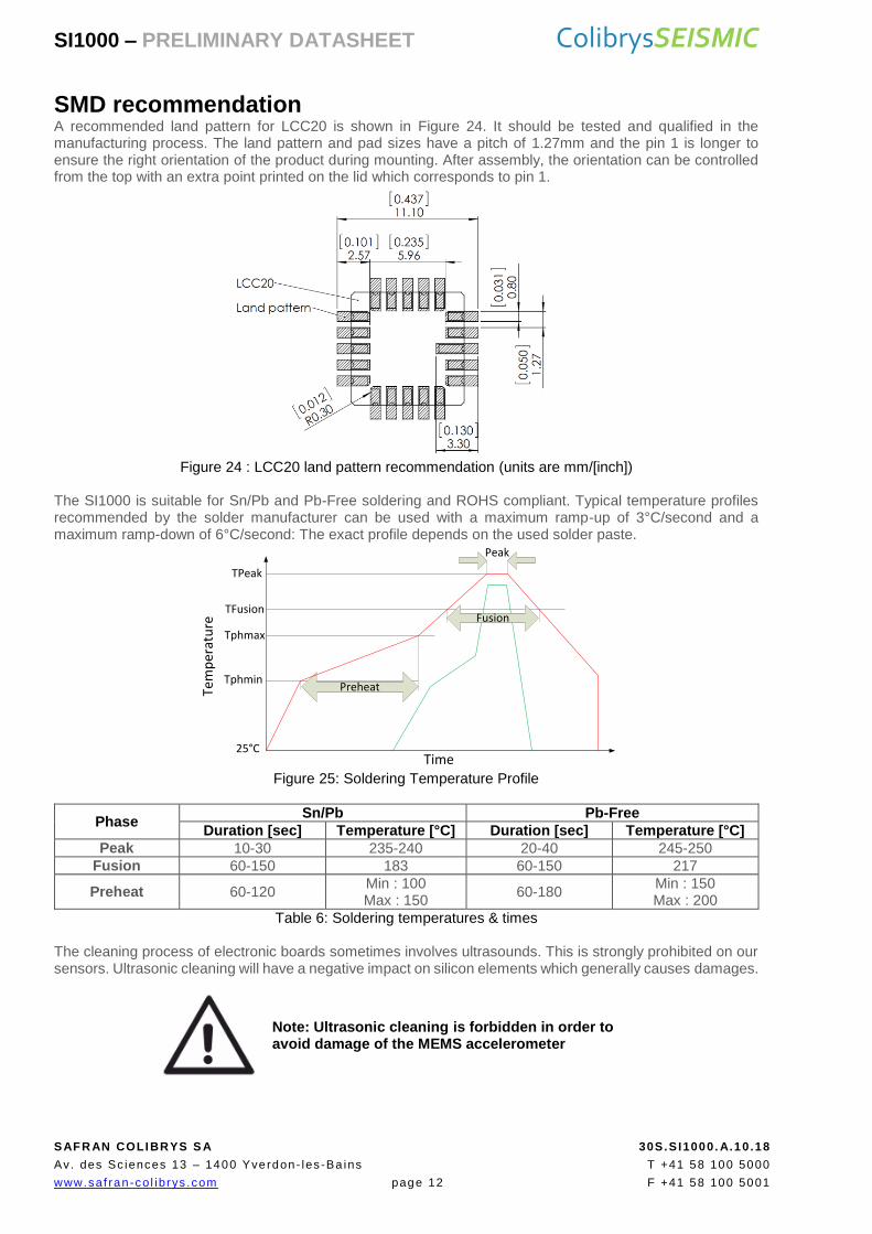
SMD recommendation A recommended land pattern for LCC20 is shown in Figure 24. It should be tested and qualified in the manufacturing process. The land pattern and pad sizes have a pitch of 1.27mm and the pin 1 is longer to ensure the right orientation of the product during mounting. After assembly, the orientation can be controlled from the top with an extra point printed on the lid which corresponds to pin 1.
Figure 24 : LCC20 land pattern recommendation (units are mm/[inch])
The SI1000 is suitable for Sn/Pb and Pb-Free soldering and ROHS compliant. Typical temperature profiles recommended by the solder manufacturer can be used with a maximum ramp-up of 3°C/second and a maximum ramp-down of 6°C/second: The exact profile depends on the used solder paste.
Figure 25: Soldering Temperature Profile
Phase Sn/Pb Pb-Free
Duration [sec] Temperature [°C] Duration [sec] Temperature [°C]
Peak 10-30 235-240 20-40 245-250
Fusion 60-150 183 60-150 217
Preheat 60-120 Min : 100 Max : 150
60-180 Min : 150 Max : 200
Table 6: Soldering temperatures & times The cleaning process of electronic boards sometimes involves ultrasounds. This is strongly prohibited on our sensors. Ultrasonic cleaning will have a negative impact on silicon elements which generally causes damages.
Note: Ultrasonic cleaning is forbidden in order to avoid damage of the MEMS accelerometer
Preheat
TPeak
TFusion
Tphmax
Tphmin
Fusion
25°CTime
Temperature
Peak

SI1000 – PRELIMINARY DATASHEET ColibrysSEISMIC
SAFR AN COLIBRYS S A 30S.SI1000. A.10.18
Av. des Sc iences 13 – 1400 Yverdon- les -Ba ins T +41 58 100 5000
www.saf ran-co l ib rys .com page 13 F +41 58 100 5001
Handling and packaging precautions
Handling The SI1000 is packaged in a hermetic ceramic housing to protect the sensor from the ambient environment. However, poor handling of the product can induce damage to the hermetic seal (Glass frit) or to the ceramic package made of brittle material (alumina). It can also induce internal damage to the MEMS accelerometer that may not be visible and cause electrical failure or reliability issues. Handle the component with caution: shocks, such as dropping the accelerometer on hard surface, may damage the product.
It is strongly recommended to use vacuum pens to manipulate the accelerometers
The component is susceptible to damage due to electrostatic discharge (ESD). Therefore, suitable precautions shall be employed during all phases of manufacturing, testing, packaging, shipment and handling. Accelerometer will be supplied in antistatic bag with ESD warning label and they should be left in this packaging until use. The following guidelines are recommended:
Always manipulate the devices in an ESD-controlled environment
Always store the devices in a shielded environment that protects against ESD damage (at minimum an ESD-safe tray and an antistatic bag)
Always wear a wrist strap when handling the devices and use ESD-safe gloves
This product can be damaged by electrostatic discharge (ESD). Handle with appropriate precautions.
Packaging
Our devices are placed in trays for shipment and SMD process. They are packed in sealed ESD-inner bag. We strongly advice to maintain our device in its original OEM sealed ESD inner-bag to guarantee storage condition before soldering them.

SI1000 – PRELIMINARY DATASHEET ColibrysSEISMIC
SAFR AN COLIBRYS S A 30S.SI1000. A.10.18
Av. des Sc iences 13 – 1400 Yverdon- les -Ba ins T +41 58 100 5000
www.saf ran-co l ib rys .com page 14 F +41 58 100 5001
Product identification markings
Ordering Information
Description Product Measurement
range
Single analog axis MEMS accelerometer,
SI1003.A ±3g
SI1005.A ±5g
SI1000 – PRELIMINARY DATASHEET ColibrysSEISMIC
SAFR AN COLIBRYS S A 30S.SI1000. A.10.18
Av. des Sc iences 13 – 1400 Yverdon- les -Ba ins T +41 58 100 5000
www.saf ran-co l ib rys .com page 15 F +41 58 100 5001
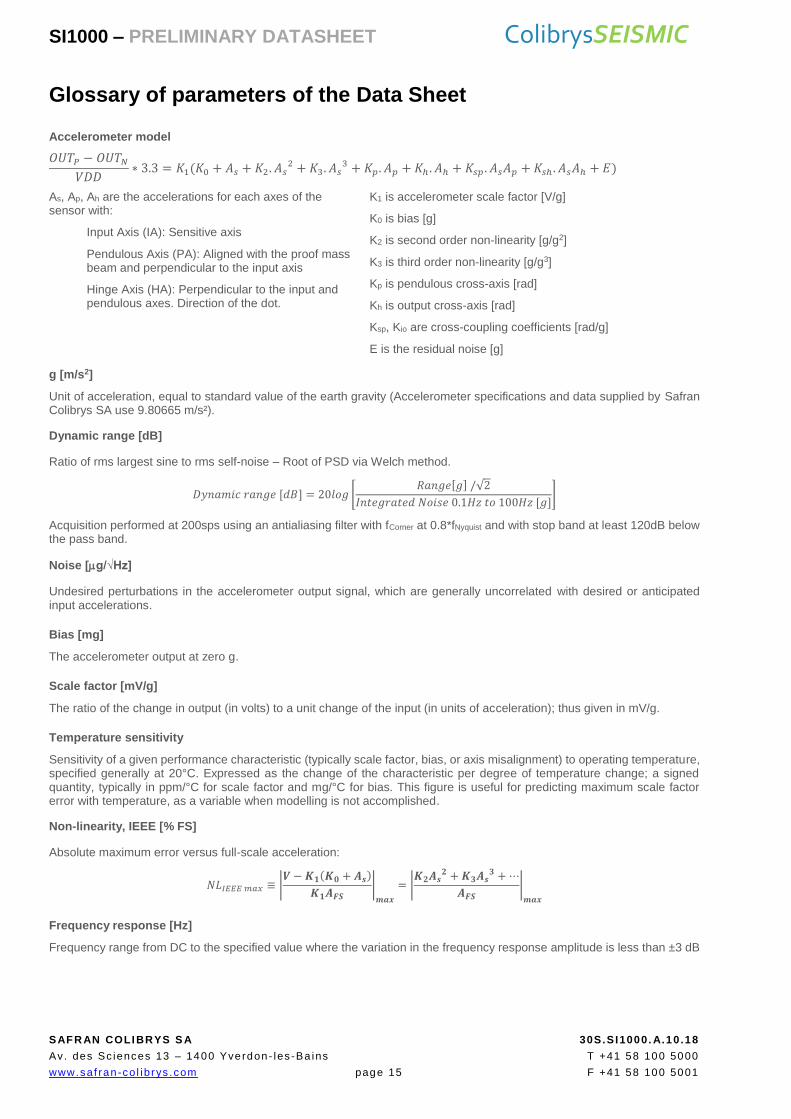
Glossary of parameters of the Data Sheet
Accelerometer model
𝑂𝑈𝑇𝑃 − 𝑂𝑈𝑇𝑁
𝑉𝐷𝐷∗ 3.3 = 𝐾1(𝐾0 + 𝐴𝑠 + 𝐾2. 𝐴𝑠
2 + 𝐾3. 𝐴𝑠3 + 𝐾𝑝. 𝐴𝑝 + 𝐾ℎ . 𝐴ℎ + 𝐾𝑠𝑝 . 𝐴𝑠𝐴𝑝 + 𝐾𝑠ℎ . 𝐴𝑠𝐴ℎ + 𝐸)
As, Ap, Ah are the accelerations for each axes of the sensor with:
Input Axis (IA): Sensitive axis
Pendulous Axis (PA): Aligned with the proof mass beam and perpendicular to the input axis
Hinge Axis (HA): Perpendicular to the input and pendulous axes. Direction of the dot.
K1 is accelerometer scale factor [V/g]
K0 is bias [g]
K2 is second order non-linearity [g/g2]
K3 is third order non-linearity [g/g3]
Kp is pendulous cross-axis [rad]
Kh is output cross-axis [rad]
Ksp, Kio are cross-coupling coefficients [rad/g]
E is the residual noise [g]
g [m/s2]
Unit of acceleration, equal to standard value of the earth gravity (Accelerometer specifications and data supplied by Safran Colibrys SA use 9.80665 m/s²).
Dynamic range [dB]
Ratio of rms largest sine to rms self-noise – Root of PSD via Welch method.
𝐷𝑦𝑛𝑎𝑚𝑖𝑐 𝑟𝑎𝑛𝑔𝑒 [𝑑𝐵] = 20𝑙𝑜𝑔 [𝑅𝑎𝑛𝑔𝑒[𝑔] /√2
𝐼𝑛𝑡𝑒𝑔𝑟𝑎𝑡𝑒𝑑 𝑁𝑜𝑖𝑠𝑒 0.1𝐻𝑧 𝑡𝑜 100𝐻𝑧 [𝑔]]
Acquisition performed at 200sps using an antialiasing filter with fCorner at 0.8*fNyquist and with stop band at least 120dB below the pass band.
Noise [g/√Hz]
Undesired perturbations in the accelerometer output signal, which are generally uncorrelated with desired or anticipated input accelerations.
Bias [mg]
The accelerometer output at zero g.
Scale factor [mV/g]
The ratio of the change in output (in volts) to a unit change of the input (in units of acceleration); thus given in mV/g.
Temperature sensitivity
Sensitivity of a given performance characteristic (typically scale factor, bias, or axis misalignment) to operating temperature, specified generally at 20°C. Expressed as the change of the characteristic per degree of temperature change; a signed quantity, typically in ppm/°C for scale factor and mg/°C for bias. This figure is useful for predicting maximum scale factor error with temperature, as a variable when modelling is not accomplished.
Non-linearity, IEEE [% FS]
Absolute maximum error versus full-scale acceleration:
𝑁𝐿𝐼𝐸𝐸𝐸 𝑚𝑎𝑥 ≡ |𝑽 − 𝑲𝟏(𝑲𝟎 + 𝑨𝒔)
𝑲𝟏𝑨𝑭𝑺|
𝒎𝒂𝒙
= |𝑲𝟐𝑨𝒔
𝟐 + 𝑲𝟑𝑨𝒔𝟑 + ⋯
𝑨𝑭𝑺|
𝒎𝒂𝒙
Frequency response [Hz]
Frequency range from DC to the specified value where the variation in the frequency response amplitude is less than ±3 dB
SI1000 – PRELIMINARY DATASHEET ColibrysSEISMIC
SAFR AN COLIBRYS S A 30S.SI1000. A.10.18
Av. des Sc iences 13 – 1400 Yverdon- les -Ba ins T +41 58 100 5000
www.saf ran-co l ib rys .com page 16 F +41 58 100 5001
Quality
Safran Colibrys is ISO 9001:2015, ISO 14001:2015 and OHSAS 18001:2007 certified
Safran Colibrys complies with the European Community Regulation on chemicals and their safe use (EC 1907/2006) REACH.
SI1000 products comply with the EU-RoHS directive 2011/65/EC (Restrictions on hazardous substances) regulations Recycling : please use appropriate recycling process for electrical and electronic components (DEEE)
SI1000 products are compliant with the Swiss LSPro : 930.11 dedicated to the security of products Note:
SI1000 accelerometers are available for sales to professionals only Les accéléromètres SI1000 ne sont disponibles à la vente que pour des
clients professionnels Die Produkte der Serie SI1000 sind nur im Vertrieb für kommerzielle
Kunden verfügbar Gli accelerometri SI1000 sono disponibili alla vendita soltanto per clienti
professionisti
Safran Colibrys complies with due diligence requirements of Section 1502, Conflict Minerals Survey, of the US Dodd-Frank Wall Street Reform and Consumer Protection Act and follows latest standard EICC/GeSI templates for Conflict Minerals declaration
Disclaimer Safran Colibrys reserves the right to make changes to products without any further notice. Performance may vary from the specifications provided in Safran Colibrys’ datasheet due to different applications and integration. Operating performance must be validated for each customer application by customer’s technical experts. The performance at system level remains the customer’s responsibility. The degolding process applied to the products is excluded from Safran Colibrys recommendations. And if applied, cancels any products warranty and liability. USE OF THE PRODUCT IN ENVIRONMENTS EXCEEDING THE ENVIRONMENTAL SPECIFICATIONS SET FORTH IN THE DATASHEET WILL VOID ANY WARRANTY. SAFRAN COLIBRYS HEREBY EXPRESSLY DISCLAIMS ALL LIABILITY RELATED TO USE OF THE PRODUCT IN ENVIRONMENTS EXCEEDING THE ENVIRONMENTAL SPECIFICATIONS SET FORTH IN THE DATASHEET.