Si Hai Mai M.-L. Nguyen-Tajan
32
RESIDUAL STRESSES IN RAILS Si Hai Mai, M.-L. Nguyen-Tajan SF2M, 13 th March 2014 SNCF - Innovation & Research, Paris
Transcript of Si Hai Mai M.-L. Nguyen-Tajan

RESIDUAL STRESSES IN RAILS
Si Hai Mai , M.-L. Nguyen-Tajan
SF2M, 13th March 2014
SNCF - Innovation & Research, Paris

Context
Context Residual stresses Crack growth simulation Conclusions
rail
Wheel
Loading cycles on the rail = a lot of trains circulations
Wheel-rail contact
(Rolling contact)
High pressure on a small
contact area
Fatigue crack in the rail
Ex: High Speed Train (TGV) = 12Tones/1cm2
Rail rolling contact fatigue is the cause of (From SNCF):~ 50% of rail fractures (taking account weld’s fracture) ~ 70% of the number of rail replacements
2

Context
Rail contact fatigue cracks• Costly maintenance operations, train delays
• Safety issues (Ex: derailment causing by rail fracture)
Objectives• Improve the understanding of the rail fatigue damage behavior
• Develop numerical tools for prediction of crack growth in the rail
• Optimize the maintenance strategy (grinding, inspection planning)
Crack size Failure
Crack detection
Crack initiation
Railreplacement
Train passages
Residual life time ?
Detection threshold
Critical size
3
Context Residual stresses Crack growth simulation Conclusions

Context From a dynamics simulation to the crack propagation
STARAILFinite element simulation
MXFATDANG VAN criterion
Rail stationary behaviour
VOCOLINMultibody train-track dynamics simulation
Contact load on the rail surface
Fatigue Initiation
IDR
2 T
ools
Train and track models
Crack growth simulation
Traffic
Crack initiation
Crack propagation
4IDR2 = Initiative for Development Research on Rail
Context Residual stresses Crack growth simulation Conclusions

Outline
I. Context
II. Residual stresses in RailsIII. Fatigue crack growth simulations
IV. Conclusions
5
Context Residual stresses Crack growth simulation Conclusions

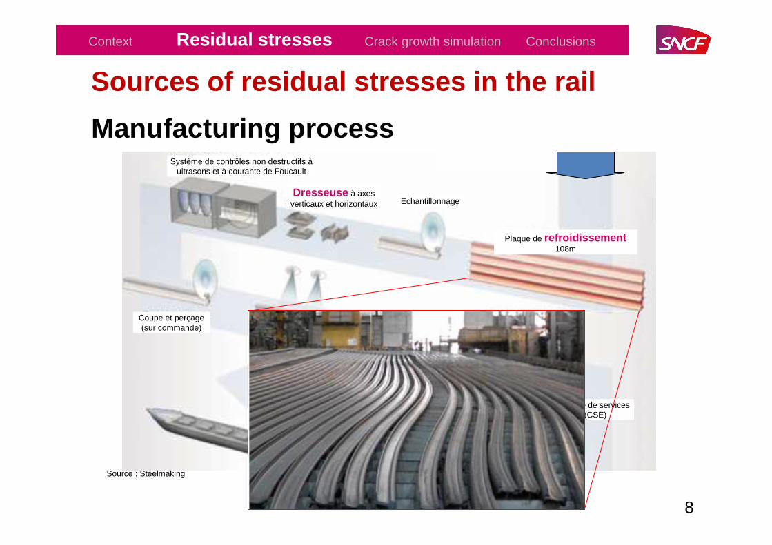
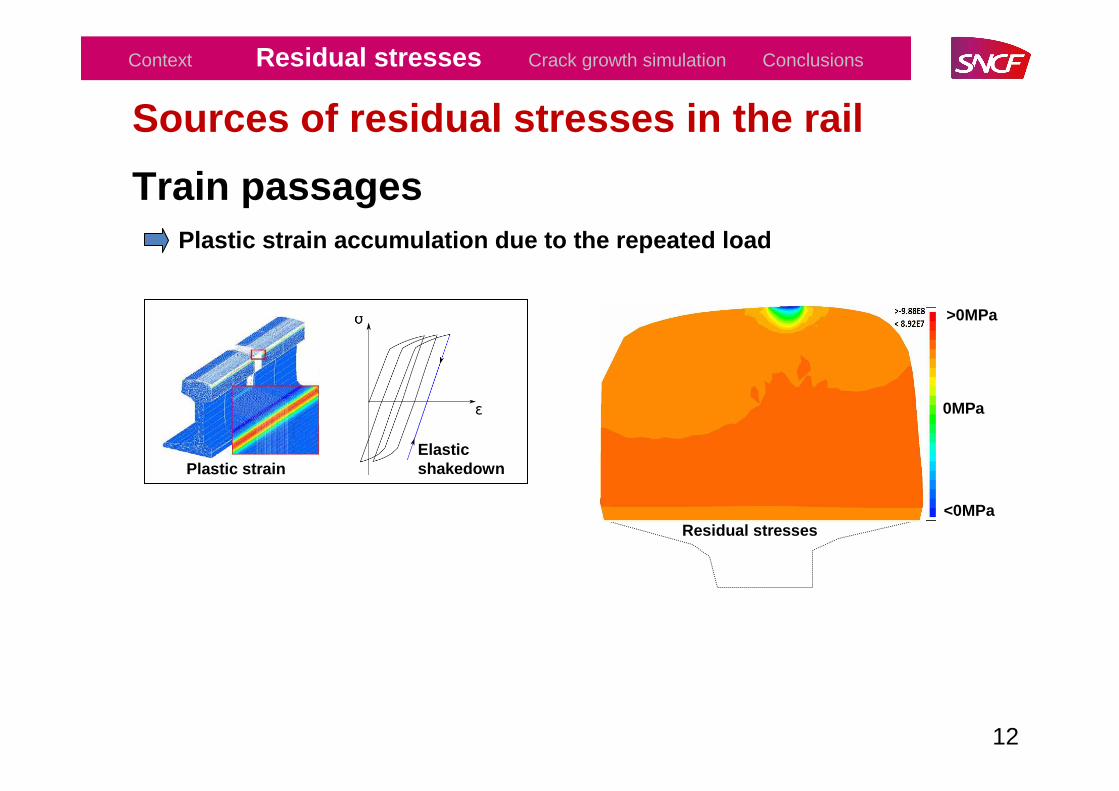
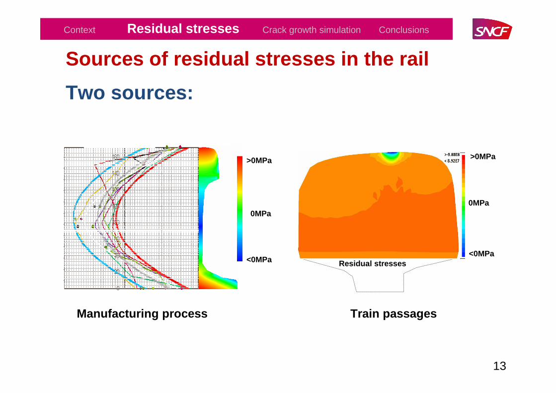
Sources of residual stresses in the rail
Two sources:
• Roller straightening = Manufacturing process
• Train passages = Plastic strain accumulation due to the repeated load
6
Context Residual stresses Crack growth simulation Conclusions
Thermal stresses (Summer – Winter) = Increase or decrease the risk of final Fracture!

Sources of residual stresses in the rail
Manufacturing process
7
Context Residual stresses Crack growth simulation Conclusions
EmbarcadèreHaut fourneauConvertisseur
Dégazage
Coulée continue
Four de réchauffementTrain ébaucheur
2 cages réversiblesFinisseur horizontal
Affinage en poche
Parc de stockage des minerais
Source : Steelmaking
Sources of residual stresses in the rail
Manufacturing process
8
Context Residual stresses Crack growth simulation Conclusions
Echantillonnage
Plaque de refroidissement108m
Dresseuse à axes verticaux et horizontaux
Système de contrôles non destructifs àultrasons et à courante de Foucault
Aire de regroupement pour inspection et pesage
Système de contrôle de la rectitude
Coupe et perçage (sur commande)
Centre de services (CSE)
Expédition
Embarcadère
Source : Steelmaking

Sources of residual stresses in the rail
Manufacturing process (Roller straightening)
9
Context Residual stresses Crack growth simulation Conclusions
Source : TataSteel
Rail
Rail
Rollers

Sources of residual stresses in the rail
Manufacturing process (Roller straightening)
10
Context Residual stresses Crack growth simulation Conclusions
Longitudinal residual stresses (MPa)
Rai
l hei
ght (
mm
)
P.A. Rodesch and S.H. Mai 2013: Intern report, SNCF – Innovation and Research
A
B
! Without thermal treatment
+-

Sources of residual stresses in the rail
Train passages
Rail
Bogie
Stresses in the rail under one bogieSTARAIL
Finite element simulation
Rail stationary behaviour [Mai.93]
VOCOLINMultibody train-track dynamics simulation
Contact load on the rail surface
Train and track models
H. Maitournam and K. DangVan 1993: J. Mech. Phys. Solids, 41 (1993) 1691-1710
11
Context Residual stresses Crack growth simulation Conclusions
Plastic strain accumulation due to the repeated loa d
Sources of residual stresses in the rail
12
Plastic strain
<0MPa
>0MPa
0MPa
Residual stresses
Elastic shakedown
Context Residual stresses Crack growth simulation Conclusions
Train passagesPlastic strain accumulation due to the repeated loa d
Sources of residual stresses in the rail
Two sources:
13
<0MPa
0MPa
>0MPa
Context Residual stresses Crack growth simulation Conclusions
Manufacturing process Train passages
<0MPa
>0MPa
0MPa
Residual stresses

Sources of residual stresses in the rail
14
Context Residual stresses Crack growth simulation Conclusions
Green : manufacturing process
Red : trains passages
Blue : global = green + red
Two sources:
Longitudinal residual stresses (MPa)
Rai
l hei
ght (
mm
)
compression
tension
tension
compression
Rail foot
Rail head
+
-
+

Procedure of integration of residual stresses
15
Context Residual stresses Crack growth simulation Conclusions
+=
+=
+=
elres
elres
elres
σσσ
εεεξξξ
−=
∇+∇=
−
= −
)(:
)(2
1
):(.1
presres
resT
resres
pres
C
CdivK
εεσ
ξξε
εξ
εres
σres
εp ε
εp - εres
Strain
εel
σel
Stress
σ
Initial state
−+=
∇+∇+∇+∇=
+−⋅
= −
)(:
)(2
1)(
2
1
):(1
presel
elT
elresT
res
elp
C
FCdivK
εεεσ
ξξξξε
εξ

Procedure of integration of residual stresses
16
Different meshes Projection
Context Residual stresses Crack growth simulation Conclusions
Stationary calculation (FEM)
Crack propagation (XFEM)

Outline
I. Context
II. Residual stresses in rails
III.Fatigue crack growth simulations
IV. Conclusions
17
Context Residual stresses Crack growth simulation Conclusions

Rolling contact fatigue : a multi-scale problem
System scale• Rail bending
Rail scale• Wheel rail contact
Crack scale• Opening/contact• Sticking sliding
18
Context Residual stresses Crack growth simulation Conclusions
Benoit TROLLE : PhD 2014, Fatigue crack propagation in rails, 20/03/2014 Lyon

Stress singularity at the crack front
Ki characterizes the sollicitations at the crack tip (= Magnitude of each cracking mode)
Methodology
Linear Elastic Fracture Mechanics
The eXtended Finite Element Method (X-FEM) [Gra.11]
• Two scale approach :U = Ubulk + Ucrack
• Two kinds of enrichment :
Discontinuous (lips displacement)
Singular (crack tip)
Gravouil, Combescure, Pommier and Moës 2011 : XFEM for crack propagation
19
Context Residual stresses Crack growth simulation Conclusions
CAST3M

Modelling of the cracked rail
l θ
µcrack
∆x
Xc
x
y
T = µwheel/rail x Pmax
Pmax
Load
Rail
1 loading cycle = 1 wheel traveling from the left to the right on the surface of the rail (quasi-static simulation)
HERTZIAN LOADING
20
Context Residual stresses Crack growth simulation Conclusions

Current tip
KI,K
II
Virtual crack
extension
θ
« Test tip »
k1*(θ) k
2*(θ)
Current crack
- Crack branching criterion: Multi-axial and non proportional loading [Hou.82]
Modelling of the cracked rail
- Multi-scale parametric mesh (software CAST3M)
- Crack growth rate law: Mixed mode (ICON) [Dub.02]
Dubourg 2002: Journal of Tribology, Vol. 124.Hourlier nad al. 1982 : Institut de Recherche de la sidérurgie française, IRSID, No RE958
21
crack
Context Residual stresses Crack growth simulation Conclusions

Calculation of SIF for one loading cycle : 2D
l θµcrack
∆x
Xc
x
y
Stress Intensity Factors (SIF) are computed for each time step (each loading position)
22
Mode:
Rail
II I+II II I+II
Context Residual stresses Crack growth simulation Conclusions

Fatigue crack growth simulation process
23
Propagation at the end of each cycle
SIF computation for each loading position
Cycle n i
Context Residual stresses Crack growth simulation Conclusions
Benoit TROLLE : PhD 2014, Fatigue crack propagation in rails

Influence of the friction coefficient between the wheel and the rail
A high tangential loading provokes earlier crack branching upwards or downwards in the rail
depending on the direction of the tangential loading.24
l θµcrack
∆x
Xc
x
y
• Pmax = 845 MPa• 2a = 13.5 mm• µwheel / rail Variable• 126 load steps using a variable ∆x• l = 6mm ; θ = 15°; µcrack = 0.5;
Inputs:
Rail
Context Residual stresses Crack growth simulation Conclusions

Initial cracks
Crack network : “squat configuration”
[Cannon1996][Steenbergen2013]
- Pmax = 845 MPa- 2a = 13.5 mm- µwheel / rail = 0.025 - Two initial cracks: µcracks = 0.01θ = 15 °
Longitudinal rail head section through a squat
[Grassie2012]
25
Inputs:
growthgrowth
Context Residual stresses Crack growth simulation Conclusions

- The crack is always closed during the first loading cycle with residual stresses (KI = 0)=> Crack growth with shear mode (KII # 0)
26
Influence of the residual stresses
SIF: one loading cycle
--- KI free--- KII free--- KI with residual stresses--- KII with residual stresses
Tension
Compression
Compression
Residual stresses in the rail’s head
Crack tip in area of high compressive stresses
Context Residual stresses Crack growth simulation Conclusions

Influence of the residual stresses
The crack branches upwards with a slower propagation rate If residual stresses are taken into account.
Free
WITH residual stresses15°Initial crack = 6mm
27
Propagation path and crack growth rate
Tension
Compression
Compression
Residual stresses in the rail’s head
Crack tip in area of high compressive stresses
8.47 105
cycles
1.63 105
cycles
Context Residual stresses Crack growth simulation Conclusions
µ = 0.025

Influence of the residual stresses
The crack branches upwards with a slower propagation rate If residual stresses are taken into account.
28
Tension
Compression
Compression
Residual stresses in the rail’s head
Crack tip in area of high compressive stresses
Context Residual stresses Crack growth simulation Conclusions

Influence of the residual stresses
Other inputs
Free
WITH residual stresses
15°Initial crack = 6mm
29
Propagation path and crack growth rate
Tension
Compression
Compression
Residual stresses in the rail’s head
Crack tip in area of high compressive stresses
Context Residual stresses Crack growth simulation Conclusions
µ = 0.4
!

Outline
I. Context
II. Residual stresses in rails
III. Fatigue crack growth simulations
IV.Conclusions
30
Context Residual stresses Crack growth simulation Conclusions

Conclusions• Two sources of residual stresses in the rail: manufacturing process (C - form) and train passages (local)
• Development of a robust numerical tool to simulate the fatigue crack growth in rails taking into account [Benoit Trollé] :
- Contact and friction between the crack lips,- Mixed mode fatigue law and non-proportional crack branching criterion,- Residual stresses (manufacturing process + train traffic),- Bending moment (not presented here).
• Rail contact fatigue crack growth simulations: Residual stresses has to be taken into account since they modify the growth rate and the propagation path.
31
Context Residual stresses Crack growth simulation Conclusions

Acknowledgments
- LaMCoS, Laboratory of contact and structural mechanics at INSA Lyon, France (M.-C. Baietto and A. Gravouil)
- CEA, French Atomic Energy Commission, in Saclay, France (B.Prabel), www-cast3m.cea.fr.
- IDR2 consortium, Initiative for Development and Research on Rails composed by SNCF, RATP, Tata Steel, IFSTTAR, MECAMIX, LAMCOS.
THANK YOU FOR YOUR ATTENTION !
32
[email protected] Mechanics and DynamicsSNCF – Innovation and Research, Paris, Francewww.recherche.sncf.com
Context Residual stresses Crack growth simulation Conclusions