Si 2321 - IMI Critical EngineeringReuther_Si2321_EN.pdf · Si 2321. 2 Si 2321 Si 2321 The regular...
8
Safety valves for pressure relief in accordance to PED, DIN/EN and ASME Engineering GREAT Solutions Si 2321
Transcript of Si 2321 - IMI Critical EngineeringReuther_Si2321_EN.pdf · Si 2321. 2 Si 2321 Si 2321 The regular...

Safety valves for pressure relief in accordance to PED, DIN/EN and ASME
Engineering GREAT Solutions
Si 2321

2
Si 2321
Si 2321
The regular safety valve for low pressures:
> Cost-effective body design with seat bushing
> Smooth and stable behaviour thanks to comparatively low lift
> Cast iron body with inner parts mainly out of stainless steel
Features
Inlet sizes DN 20 to DN 150
Pressure ratingPN 10 to PN 16
Set pressures0.45 bar g to 16 bar g
Temperature range-10 °C to +300 °C
OverpressureVapours/gases 10%Liquids 10%
BlowdownVapours/gases 10%Liquids 20%
Allowable built-up back pressure15% of set pressure
> For vapours, gases and liquids
> Protecting the systems downstream of control valves
> Water supply up to PN 16
> Approved for drinking water
Applications
Approvals and standards
EC type examination
- Pressure Equipment Directive 97/23/EC
- DIN EN ISO 4126-1
- AD2000-Merkblatt A2
- VdTÜV Merkblatt “Sicherheitsventil 100”
VdTÜV type approval acc. to
TÜV.SV.12-209.d0.D / G / F.aw.p
IMI Bopp & Reuther will not renew the exis ting VdTÜV type approvals. The requi rements by VdTÜV and applicable standards are completely considered by the EC type examination.
The design, manufacture, testing and labelling meet the requirements of DIN EN ISO 4126-1, DIN EN 12266-1/-2 (insofar as applicable for safety valves), EN 1092-1, EN 1759-1, AD 2000-Merk-blätter A2 and HP0, ASME B16.5, ASME VIII
Stable opening response with very low lift
Stainless steel inner parts
Internally coated for water supply systems use
3
Si 2321
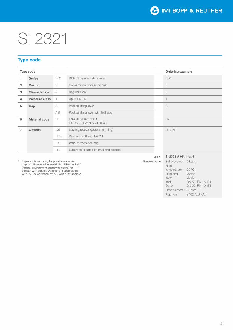
Type code Ordering example
1 Series Si 2 DIN/EN regular safety valve Si 2
2 Design 3 Conventional, closed bonnet 3
3 Characteristic 2 Regular Flow 2
4 Pressure class 1 Up to PN 16 1
5 Cap A Packed lifting lever A
AB Packed lifting lever with test gag
6 Material code 05 EN-GJL-250 / 5.1301 GG25 / 0.6025 / EN-JL 1040
05
7 Options .09 Locking sleeve (government ring) .11a .41
.11a Disc with soft seal EPDM
.35 With lift restriction ring
.41 Luberpox1) coated internal and external
Si 2321 A 05 .11a .41
Set pressure 6 bar gFluid temperature 20 °CFluid and Water state LiquidInlet DN 50, PN 16, B1 Outlet DN 50, PN 10, B1Flow diameter 32 mmApproval 97/23/EG (CE)
Type
Please state:
Type code
1) Luperpox is a coating for potable water and approved in accordance with the “UBA-Leitlinie” (federal environment agency guideline) for contact with potable water and in accordance with DVGW worksheet W 270 with KTW approval.

4
Si 2321
Si 2321
0.0
0.1
0.2
0.3
0.4
0.5
0.00 0.02 0.04 0.06 0.08 0.10
αw
[−]
h/d0 [−]
0.0
0.1
0.2
0.3
0.4
0.5
0.0
0.1
0.2
0.3
0.4
0.5
0.6
0.7
0.8
0.9
0.1 0.2 0.3 0.4 0.5 0.6 0.7 0.8 0.9 1.0
αW
[−]
pb/p0 [−]0.00 0.1 0.30.20.02 0.40.04 0.50.06 0.60.08 0.70.10 0.8 0.9 1.0
h/d0[–] pb/p0 [–]
0.5 0.9
0.8
0.7
0.6
0.5
0.4
0.4
0.3
0.3
0.1
0.1
0.2
0.2
0.0 0.0
aw
[–]
aw
[–]
Si 2321 coefficient of discharge aw depending on h / d0 for gases and vapours, liquids
Si 2321 coefficient of discharge aw depending on pb/p0 for gases and vapours
The coefficients of discharge Kdr acc. to DIN EN ISO 4126-1 for this valve series are identical to the above coefficients of discharge aw and the values in the diagrams.
h = Lift [mm]d0 = Flow diameter of the selected safety valve
[mm]h/d0 = Lift/flow diameter ratiopb = Absolute back pressure [bar a]p0 = Absolute relieving pressure [bar a]
pb/p0 = Absolute back pressure/absolute relieving pressure ratio
aw = Coefficient of discharge acc. to AD 2000-Merkblatt A2qm = Required mass flow [kg/hr]qmc = Certified mass flow [kg/hr]
Fluid group Inlet size Flow diameter h/d0 ≥Pressure p0 ≥ [bar g] pb/p0 ≤ aw
Vapours/gases (D / G) DN 20 to DN 150 12 mm to 93 mm 0.1 0.6 0.62 0.25
Liquids (F) DN 20 to DN 150 12 mm to 93 mm 0.1 0.45 - 0.25
The coefficient of discharge for gases/vapours in a pressure ratio of pb/p0 > 0.62 is shown in the diagram below.
The capacity of the safety valve can be adjusted to the required capacity by reducing the lift, thus reducing an undesirable extra performance.
The following applies aw(reduced) = aw x qm/qmc. The required ratio h/d0 is shown in the diagram below, and the reduced lift calculated with h(reduced) = d0 x (h/d0).
d0 = 12 -93 mm d0 = 12 -93 mm
Coefficient of discharge
5
Si 2321
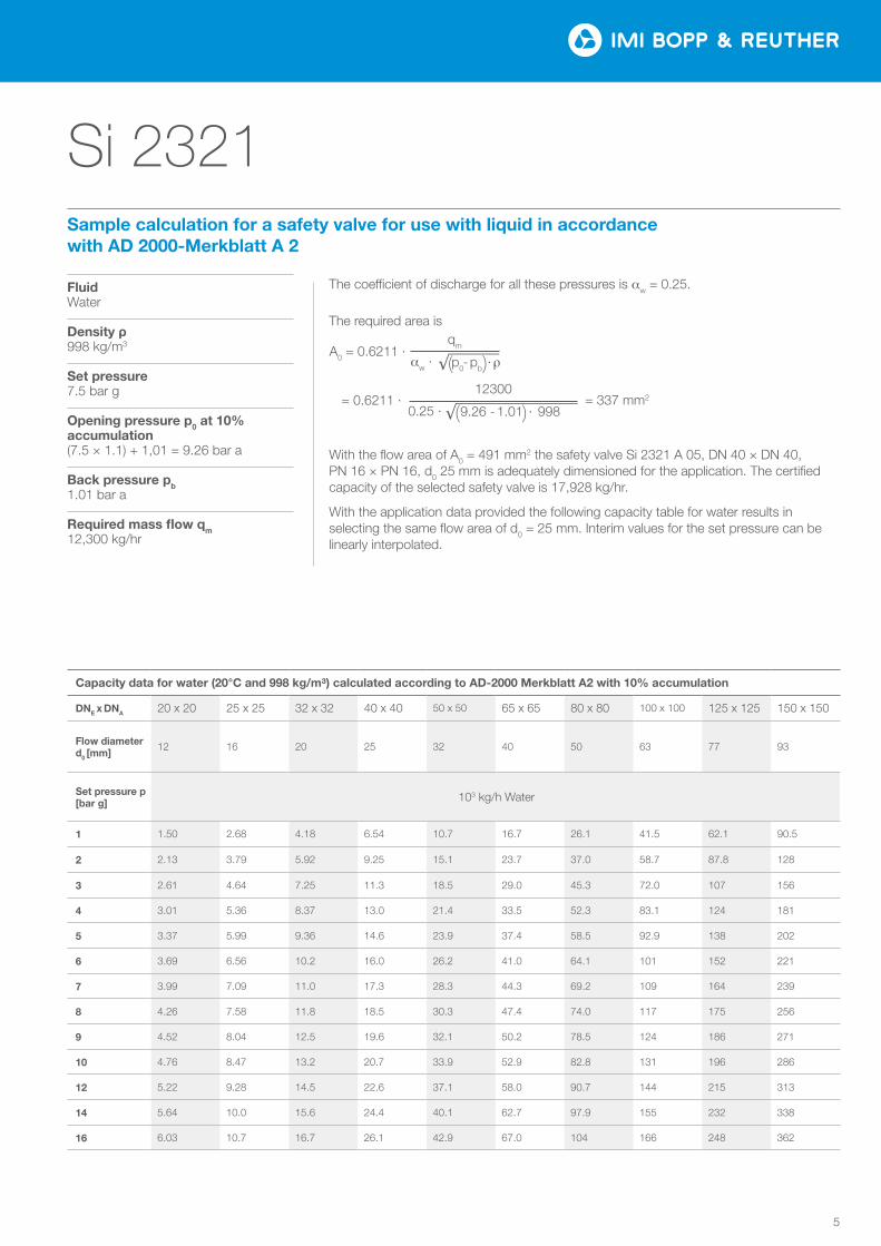
FluidWater
Density ρ998 kg/m3
Set pressure7.5 bar g
Opening pressure p0 at 10% accumulation(7.5 × 1.1) + 1,01 = 9.26 bar a
Back pressure pb1.01 bar a
Required mass flow qm 12,300 kg/hr
The required area is
With the flow area of A0 = 491 mm2 the safety valve Si 2321 A 05, DN 40 × DN 40, PN 16 × PN 16, d0 25 mm is adequately dimensioned for the application. The certified capacity of the selected safety valve is 17,928 kg/hr.
With the application data provided the following capacity table for water results in selecting the same flow area of d0 = 25 mm. Interim values for the set pressure can be linearly interpolated.
The coefficient of discharge for all these pressures is aw = 0.25.
Sample calculation for a safety valve for use with liquid in accordance with AD 2000-Merkblatt A 2
qm
aw · A0 = 0.6211 ·
p0- pb ·ρ
= 337 mm2 12300
0.25 · = 0.6211 ·
9.26 - 1.01 · 998
Capacity data for water (20°C and 998 kg/m³) calculated according to AD-2000 Merkblatt A2 with 10% accumulation
DNE x DNA 20 x 20 25 x 25 32 x 32 40 x 40 50 x 50 65 x 65 80 x 80 100 x 100 125 x 125 150 x 150
Flow diameter d0 [mm]
12 16 20 25 32 40 50 63 77 93
Set pressure p [bar g] 103 kg/h Water
1 1.50 2.68 4.18 6.54 10.7 16.7 26.1 41.5 62.1 90.5
2 2.13 3.79 5.92 9.25 15.1 23.7 37.0 58.7 87.8 128
3 2.61 4.64 7.25 11.3 18.5 29.0 45.3 72.0 107 156
4 3.01 5.36 8.37 13.0 21.4 33.5 52.3 83.1 124 181
5 3.37 5.99 9.36 14.6 23.9 37.4 58.5 92.9 138 202
6 3.69 6.56 10.2 16.0 26.2 41.0 64.1 101 152 221
7 3.99 7.09 11.0 17.3 28.3 44.3 69.2 109 164 239
8 4.26 7.58 11.8 18.5 30.3 47.4 74.0 117 175 256
9 4.52 8.04 12.5 19.6 32.1 50.2 78.5 124 186 271
10 4.76 8.47 13.2 20.7 33.9 52.9 82.8 131 196 286
12 5.22 9.28 14.5 22.6 37.1 58.0 90.7 144 215 313
14 5.64 10.0 15.6 24.4 40.1 62.7 97.9 155 232 338
16 6.03 10.7 16.7 26.1 42.9 67.0 104 166 248 362

6
Si 2321
23
24
1617
18143015
35413121011622872
1
19
Si 2321
Materialcode 05
Temperature application range -10 °C to +300 °C
Part Name Material
1 Body EN-GJL-250 / 5.1301 GG25 / 0.6025 / EN-JL 1040
2 Seat bushing 1.4122
3 Stud, short 5.6
4 Stud, long 5.6
5 Hexagon nut 5
6 Disc holder 0.7040
7 Disc 3) 1.4122
8 Disc retainer 1.4571
10 Flat gasket 1.4401 / Graphite
11 Intermediate cover 1) 1.4122 1.4059
12 Pressure sleeve 1.4122
13 Spring washer, bottom 1.0038
14 Spring washer, top 1.0038
15 Bonnet EN-GJL-250 / 5.1301 GG25 / 0.6025 / EN-JL 1040
16 Adjusting screw 1.4104
17 Locknut 5
18 Spindle 1.4021
19 Flat gasket 1.4401 / Graphite
22 Ring (two-parts) 1.4122
23 Lifting lever 2) 0.7040
24 Lifting nut 1.4021
30 Spring 4) 1.1200 1.8159
1) Intermediate cover to DN 80 made from 1.4122, above that made from 1.4059
2) Packed lifting lever (cap) from DN 150 flanged
3) Disc material may be upgraded to stellited 1.4571 upon request for safety valves in saturated steam service
4) The spring material selection depends on the valve size and set pressure
IMI Bopp & Reuther reserve the right to technical changes or application of higher quality materials without prior notice. The material design can be tailored to customer specifications at any time upon request.
Material code

7
Si 2321
H1
S1
S2
Si 2321
SizeDNE 20 25 32 40 50 65 3) 80 100 125 150
DNA20 25 32 40 50 65 3) 80 100 125 150
Flow diameter [mm]
12 16 20 25 32 40 50 63 77 93
Flow area [mm²]
113 201 314 491 804 1257 1964 3117 4657 6793
Min. set pressure [bar g]
0.45
Max. set pressure [bar g] 1)
16
Max. back pressure [bar g]
4
Inlet flange DIN EN 2)
PN 10
PN 16
Outlet flange DIN EN 2)
PN 10
PN 16
Centre to face dimension S1 [mm]
95 100 105 115 125 145 155 175 200 225Centre to face dimension S2 [mm]
Height H1 [mm]
335 350 390 420 495 550 655 705 810 850
Weight [kg] 8 9 11 13 18 26 38 52 80 90
1) Stated pressures are maximum values corresponding to the spring forces. The component strength may need to be reviewed depending on the material and temperature.
2) Flanges PN 10 / 16 acc. to DIN EN 1092-2; flange facing Type B1
3) 4-hole flange drilling with DN 65 PN 10 / 16
Sizes, pressure ranges and dimensions

IMI Critical Engineering Lakeside, Solihull Parkway Birmingham Business Park Birmingham B37 7XZ United Kingdom
Tel: +44 (0)121 717 3700 Fax: +44 (0)121 717 3701
www.imi-critical.com
IMI Bopp & Reuther Bopp & Reuther Sicherheits- und Regelarmaturen GmbH Carl-Reuther-Straße 1 68305 Mannheim Deutschland
Tel: +49 (0)621 76220-100 Fax: +49 (0)621 76220-120
www.imi-critical.com [email protected]