Short circuit calculations
8
7 Electrical Plan Review Point-To-Point Method Of Short-Circuit Calculation Adequate interrupting rating and protection of electrical components are two essential aspects required by the NEC ® 110.3(B), 110.9, 110.10, 240.1, 250.4, 250.90, 250.96, and Table 250.122 Note. The first step to ensure that system protective devices have the prop- er interrupting rating and provide component protection is to determine the available short-circuit currents. The application of the Point-To- Point method can be used to determine the available short-circuit cur- rents with a reasonable degree of accuracy at various points for either 3f or 1f electrical distribution systems. The example shown here assumes unlimited primary short-circuit current (infinite bus). Calculation Of Short-Circuit Currents — Point-To-Point Method. Example Of 3-Phase Short-Circuit Calculation Basic Short-Circuit Calculation Procedure. Procedure Step 1 Determine transf. full-load amperes from either: a) Name plate b) Tables 3A & 3B c) Formula Step 2 Find transformer multiplier See Note 3. Step 3 Determine transf. let-through short- circuit current (Formula or Table 5) See Note 1 and Note 4. Step 4 Calculate “f” factor. Step 5 Calculate “M” (multiplier) or take from Table 4. Step 6 Compute the available short- circuit current (RMS symmetrical) See Note 1, Note 2, and Note 5 3o transf. IFLA = † I SCA = Transf.FLA x multiplier † I SCA (L-L-L) = 46,273 x .852 = 39,425A (Use I SCA (L-L-L) at Fault #1 to calculate) ** I SCA (L-L-L) = 833 X 55.55 = 46,273 KVA x 1000 EL-L x 1.73 KVA x 1000 EL-L x 1.732 IFLA = = = 833A KVA x 1000 EL-L x 1.732 300 x 1000 208 x 1.732 100 1.8 3o faults f = 1.732 x L x lL-L-L C x n x EL-L f = 1.732 x L x lL-L-L C x n x EL-L 1.732 x 20 x 46,273 22,185 x 2 x 208 f = 1.732 x 20 x 39,425 5,907 x 1 x 208 2 x L x l L-L C x n x EL-L 100 Transf. % Z 1o transf. IFLA = Multiplier = 100 ††.9x Transf. % Z Multiplier = KVA x 1000 EL-L f = 1 † I SCA = I SCA x M 1 + f M = 1 1 + f 1 1 + .174 M = 2 x L x l L-N* C x n x EL-N f = 1o line-to-line (L-L) faults See Note 5 1o line-to-neutral (L-N) faults See Note 2 and Note 5 L = length (feet) of conduit to the fault. C = conductor constant. See Tables 1, 2. n = number of conductors per phase (Adjusts C value for parallel runs) I = available short-circuit current in amperes at beginning of circuit. Formula FAULT #1 at fault at beginning of circuit. Note 1. Motor short-circuit contribution, if significant, should be added at all fault locations throughout the system. A practical estimate of motor short-circuit contri- bution is to multiply the total motor full-load current in amperes by 4. Values of 4 to 6 are commonly accepted Note 2. For single-phase center-tapped transformers, the L-N fault current is higher than the L-L fault current at the secondary terminals. The short-circuit current available (I) for this case in Step 4 should be adjusted at the transformer terminals as follows: At L-N center tapped transformer terminals IL-N = 1.5 x IL-L at Transformer Terminals At some distance from the terminals, depending upon wire size, the L-N fault current is lower than the L-L fault current. The 1.5 multiplier is an approximation and will theoret- ically vary from 1.33 to 1.67. These figures are based on change in turns ratio between primary and secondary, infinite source available, zero feet from terminals of trans- former, and 1.2 x %X and 1.5 x %R for L-N vs. L-L resistance and reactance values. Begin L-N calculations at transformer secondary terminals, then proceed point-to-point. † * 300 KVA, 2%Z, 3f 120/208V Secondary 20', (2) 4-500 kcmil CU Steel conduit 20', 4 - 2 AWG CU Steel conduit Infinite Primary Available Fault #2 Fault #1 MAIN SERVICE PANEL BRANCH CIRCUIT PANEL Step 1 Step 2 Step 3 Step 4 Step 5 Step 6 Step 4 Step 5 Step 6 = = = = .174 = 1.11 = .852 (See Table 4) 1 1 + f 1 1 + 1.11 M = = = .474 (See Table 4) = 55.55 3-Phase Short-Circuit Current at Transformer Secondary 3-Phase Short Circuit Current at Fault #1 † I SCA (L-L-L) = 39,425 x .474 = 18,687A 3-Phase Short-Circuit Current at Fault #2 FAULT #2 ** The motor contribution and voltage variance should be accounted for at this point. See Notes 1 and 4. †† Transformer %Z is multiplied by .9 to establish a worst case condition. See Note 3. Note 3: The marked impedance values on transformers may vary ±10% from the actual values determined by ANSI / IEEE test. See U.L. Standard 1561. Therefore, multiply transformer %Z by .9. Transformers constructed to ANSI standards have a ± 7.5% impedance tolerance (two-winding construction). Note 4. Utility voltages may vary ±10% for power, and ±5.8% for 120-volt light- ing services. Therefore, for worst case conditions, multiply values as calculated in Step 3 by 1.1 and/or 1.058 respectively. Note 5: The calculated short-circuit currents above represent the bolted fault values that approximate worst case conditions. Approximations of Bolted fault values as percentage of 3-Phase (L-L-L) bolted fault values are shown below. Phase-Phase (L-L): 87% Phase-Ground (L-G) 25-125% (Use 100% near transformer, 50% otherwise) Phase-Neutral (L-N) 25-125% (Use 100% near transformer, 50% otherwise) Note 6: Approximation of arcing fault values for sustained arcs as percentage of 3-Phase (L-L-L) bolted fault values are shown below. 3-Phase (L-L-L) Arching Fault Phase-Phase (L-L) Arcing Fault Phase-Ground (L-G) Arcing Fault 89% (maximum) 74% (maximum) 38% (minimum)
-
Upload
mustafa-ismail -
Category
Engineering
-
view
577 -
download
2
Transcript of Short circuit calculations

7
Electrical Plan Review
Point-To-Point Method Of Short-Circuit Calculation
Adequate interrupting rating and protection of electrical componentsare two essential aspects required by the NEC® 110.3(B), 110.9,110.10, 240.1, 250.4, 250.90, 250.96, and Table 250.122 Note. The first step to ensure that system protective devices have the prop-er interrupting rating and provide component protection is to determinethe available short-circuit currents. The application of the Point-To-Point method can be used to determine the available short-circuit cur-rents with a reasonable degree of accuracy at various points for either3f or 1f electrical distribution systems. The example shown hereassumes unlimited primary short-circuit current (infinite bus).
Calculation Of Short-Circuit Currents —Point-To-Point Method.
Example Of 3-Phase Short-Circuit Calculation
Basic Short-Circuit Calculation Procedure.Procedure
Step 1 Determine transf.full-load amperesfrom either:a) Name plateb) Tables 3A & 3Bc) Formula
Step 2 Find transformermultiplierSee Note 3.
Step 3 Determine transf.let-through short-circuit current(Formula or Table 5)See Note 1 and Note 4.
Step 4 Calculate“f” factor.
Step 5 Calculate “M”(multiplier) or takefrom Table 4.
Step 6 Compute theavailable short-circuit current(RMS symmetrical)See Note 1, Note 2, and Note 5
3o transf. IFLA =
†ISCA = Transf.FLA x multiplier
†ISCA (L-L-L) = 46,273 x .852 = 39,425A
(Use ISCA (L-L-L) at Fault #1 to calculate)
** ISCA (L-L-L) = 833 X 55.55 = 46,273
KVA x 1000EL-L x 1.73
KVA x 1000EL-L x 1.732
IFLA = = = 833AKVA x 1000EL-L x 1.732
300 x 1000208 x 1.732
1001.8
3o faults f = 1.732 x L x lL-L-L
C x n x EL-L
f = 1.732 x L x lL-L-L
C x n x EL-L
1.732 x 20 x 46,27322,185 x 2 x 208
f = 1.732 x 20 x 39,4255,907 x 1 x 208
2 x L x lL-L
C x n x EL-L
100Transf. % Z
1o transf. IFLA =
Multiplier =
100††.9x Transf. % Z
Multiplier =KVA x 1000EL-L
f =
1
†ISCA = ISCA x M
1 + fM =
11 + f
11 + .174M =
2 x L x lL-N*C x n x EL-N
f =
1o line-to-line(L-L) faults See Note 5
1o line-to-neutral(L-N) faults See Note 2 andNote 5
L = length (feet) of conduit to the fault.C = conductor constant. See Tables 1, 2.n = number of conductors per phase
(Adjusts C value for parallel runs)I = available short-circuit current in
amperes at beginning of circuit.
Formula FAULT #1
atfault
atbeginning of circuit.
Note 1. Motor short-circuit contribution, if significant, should be added at all faultlocations throughout the system. A practical estimate of motor short-circuit contri-bution is to multiply the total motor full-load current in amperes by 4. Values of 4 to6 are commonly acceptedNote 2. For single-phase center-tapped transformers, the L-N fault current is higherthan the L-L fault current at the secondary terminals. The short-circuit current available(I) for this case in Step 4 should be adjusted at the transformer terminals as follows:At L-N center tapped transformer terminalsIL-N = 1.5 x IL-L at Transformer Terminals
At some distance from the terminals, depending upon wire size, the L-N fault current islower than the L-L fault current. The 1.5 multiplier is an approximation and will theoret-ically vary from 1.33 to 1.67. These figures are based on change in turns ratio betweenprimary and secondary, infinite source available, zero feet from terminals of trans-former, and 1.2 x %X and 1.5 x %R for L-N vs. L-L resistance and reactance values.Begin L-N calculations at transformer secondary terminals, then proceed point-to-point.
†
*
300 KVA, 2%Z, 3f120/208V Secondary
20', (2) 4-500 kcmil CUSteel conduit 20', 4 - 2 AWG CU
Steel conduit
InfinitePrimaryAvailable
Fault #2
Fault #1
MAIN SERVICEPANEL
BRANCH CIRCUIT PANEL
Step 1
Step 2
Step 3
Step 4
Step 5
Step 6
Step 4
Step 5
Step 6
=
=
=
= .174
= 1.11
= .852 (See Table 4)
11 + f
11 + 1.11M = = = .474 (See Table 4)
= 55.55
3-Phase Short-Circuit Current at Transformer Secondary
3-Phase Short Circuit Current at Fault #1
†ISCA (L-L-L) = 39,425 x .474 = 18,687A3-Phase Short-Circuit Current at Fault #2
FAULT #2
**The motor contribution and voltage variance should be accounted for at thispoint. See Notes 1 and 4.††Transformer %Z is multiplied by .9 to establish a worst case condition. See Note 3.
Note 3: The marked impedance values on transformers may vary ±10% fromthe actual values determined by ANSI / IEEE test. See U.L. Standard 1561.Therefore, multiply transformer %Z by .9. Transformers constructed to ANSIstandards have a ± 7.5% impedance tolerance (two-winding construction).
Note 4. Utility voltages may vary ±10% for power, and ±5.8% for 120-volt light-ing services. Therefore, for worst case conditions, multiply values as calculatedin Step 3 by 1.1 and/or 1.058 respectively.
Note 5: The calculated short-circuit currents above represent the bolted faultvalues that approximate worst case conditions. Approximations of Bolted faultvalues as percentage of 3-Phase (L-L-L) bolted fault values are shown below.
Phase-Phase (L-L): 87% Phase-Ground (L-G) 25-125% (Use 100% near transformer, 50% otherwise)Phase-Neutral (L-N) 25-125% (Use 100% near transformer, 50% otherwise)
Note 6: Approximation of arcing fault values for sustained arcs as percentageof 3-Phase (L-L-L) bolted fault values are shown below.
3-Phase (L-L-L) Arching Fault
Phase-Phase (L-L) Arcing Fault
Phase-Ground (L-G) Arcing Fault
89% (maximum)
74% (maximum)
38% (minimum)
8
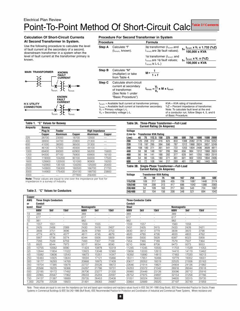
Voltage(Line-to- Transformer KVA RatingLine) 45 75 112.5 150 225 300 500 750 1000 1500 2000208 125 208 312 416 625 833 1388 2082 2776 4164 5552220 118 197 295 394 590 787 1312 1968 2624 3937 5249240 108 180 271 361 541 722 1203 1804 2406 3609 4811440 59 98 148 197 295 394 656 984 1312 1968 2624460 56 94 141 188 282 377 628 941 1255 1883 2510480 54 90 135 180 271 361 601 902 1203 1804 2406600 43 72 108 144 217 289 481 722 962 1443 1925
Electrical Plan Review
Point-To-Point Method Of Short-Circuit Calculation
Ampacity BuswayPlug-In Feeder High ImpedanceCopper Aluminum Copper Aluminum Copper
225 28700 23000 18700 12000 — 400 38900 34700 23900 21300 — 600 41000 38300 36500 31300 — 800 46100 57500 49300 44100 — 1000 69400 89300 62900 56200 156001200 94300 97100 76900 69900 161001350 119000 104200 90100 84000 175001600 129900 120500 101000 90900 192002000 142900 135100 134200 125000 204002500 143800 156300 180500 166700 217003000 144900 175400 204100 188700 238004000 — — 277800 256400 —Note: These values are equal to one over the impedance per foot forimpedance in a survey of industry.
Voltage Transformer KVA Rating25 50 75 100 167 250 333 500
115/230 109 217 326 435 726 1087 1448 2174120/240 104 208 313 417 696 1042 1388 2083230/460 54 109 163 217 363 543 724 1087240/480 52 104 156 208 348 521 694 1042
Calculation Of Short-Circuit CurrentsAt Second Transformer In System.Use the following procedure to calculate the levelof fault current at the secondary of a second,downstream transformer in a system when thelevel of fault current at the transformer primary isknown.
Step A Calculate “f”(ISCA(P), known).
Step B Calculate “M”(multiplier) or takefrom Table 4.
Step C Calculate short-circuitcurrent at secondaryof transformer.(See Note 1 under“Basic Procedure”)
3o transformer (ISCA(P) andISCA(S) are 3o fault values).
1o transformer (ISCA(P) andISCA(S) are 1o fault values;ISCA(S) is L-L.)
Procedure
Procedure For Second Transformer in SystemFormula
ISCA(P) = Available fault current at transformer primary.ISCA(S) = Available fault current at transformer secondary.VP = Primary voltage L-L.VS = Secondary voltage L-L.
KVA = KVA rating of transformer.%Z = Percent impedance of transformer.Note: To calculate fault level at the endof a conductor run, follow Steps 4, 5, and 6of Basic Procedure.
f=100,000 x KVAISCA(P) x VP x 1.732 (%Z)
ISCA(S) =VP x M x ISCA(P)
f=100,000 x KVAISCA(P) x VP x (%Z)
M =1 + f
1
VS
Table 3A. Three-Phase Transformer—Full-LoadCurrent Rating (In Amperes)
Table 1. “C” Values for Busway
Table 3B. Single-Phase Transformer—Full-LoadCurrent Rating (In Amperes)
MAIN TRANSFORMER
H.V. UTILITYCONNECTION
KNOWNFAULTCURRENT
KNOWNFAULTCURRENT
Table 2. “C” Values for Conductors
CopperAWG Three Single Conductors Three-Conductor Cableor Conduit Conduitkcmil Steel Nonmagnetic Steel Nonmagnetic
600V 5kV 15kV 600V 5kV 15kV 600V 5kV 15kV 600V 5kV 15kV14 389 - - 389 - - 389 - - 389 - -12 617 - - 617 - - 617 - - 617 - -10 981 - - 982 - - 982 - - 982 - -8 1557 1551 - 1559 1555 - 1559 1557 - 1560 1558 -6 2425 2406 2389 2430 2418 2407 2431 2425 2415 2433 2428 24214 3806 3751 3696 3826 3789 3753 3830 3812 3779 3838 3823 37983 4774 4674 4577 4811 4745 4679 4820 4785 4726 4833 4803 47622 5907 5736 5574 6044 5926 5809 5989 5930 5828 6087 6023 59581 7293 7029 6759 7493 7307 7109 7454 7365 7189 7579 7507 73641/0 8925 8544 7973 9317 9034 8590 9210 9086 8708 9473 9373 90532/0 10755 10062 9390 11424 10878 10319 11245 11045 10500 11703 11529 110533/0 12844 11804 11022 13923 13048 12360 13656 13333 12613 14410 14119 134624/0 15082 13606 12543 16673 15351 14347 16392 15890 14813 17483 17020 16013250 16483 14925 13644 18594 17121 15866 18311 17851 16466 19779 19352 18001300 18177 16293 14769 20868 18975 17409 20617 20052 18319 22525 21938 20163350 19704 17385 15678 22737 20526 18672 22646 21914 19821 24904 24126 21982400 20566 18235 16366 24297 21786 19731 24253 23372 21042 26916 26044 23518500 22185 19172 17492 26706 23277 21330 26980 25449 23126 30096 28712 25916600 22965 20567 17962 28033 25204 22097 28752 27975 24897 32154 31258 27766750 24137 21387 18889 29735 26453 23408 31051 30024 26933 34605 33315 297351,000 25278 22539 19923 31491 28083 24887 33864 32689 29320 37197 35749 31959
ISCA(P) ISCA(S)
ISCA(P) ISCA(S)
Note: These values are equal to one over the impedance per foot and based upon resistance and reactance values found in IEEE Std 241-1990 (Gray Book), IEEE Recommended Practice for Electric PowerSystems in Commerical Buildings & IEEE Std 242-1986 (Buff Book), IEEE Recommended Practice for Protection and Coordination of Industrial and Commercial Power Systems. Where resistance and

9
Electrical Plan Review
Point-To-Point Method Of Short-Circuit Calculation
AluminumAWG Three Single Conductors Three-Conductor Cableor Conduit Conduitkcmil Steel Nonmagnetic Steel Nonmagnetic
600V 5kV 15kV 600V 5kV 15kV 600V 5kV 15kV 600V 5kV 15kV14 237 - - 237 - - 237 - - 237 - -12 376 - - 376 - - 376 - - 376 - -10 599 - - 599 - - 599 - - 599 - -8 951 950 - 952 951 - 952 951 - 952 952 -6 1481 1476 1472 1482 1479 1476 1482 1480 1478 1482 1481 14794 2346 2333 2319 2350 2342 2333 2351 2347 2339 2353 2350 23443 2952 2928 2904 2961 2945 2929 2963 2955 2941 2966 2959 29492 3713 3670 3626 3730 3702 3673 3734 3719 3693 3740 3725 37091 4645 4575 4498 4678 4632 4580 4686 4664 4618 4699 4682 46461/0 5777 5670 5493 5838 5766 5646 5852 5820 5717 5876 5852 57712/0 7187 6968 6733 7301 7153 6986 7327 7271 7109 7373 7329 72023/0 8826 8467 8163 9110 8851 8627 9077 8981 8751 9243 9164 89774/0 10741 10167 9700 11174 10749 10387 11185 11022 10642 11409 11277 10969250 12122 11460 10849 12862 12343 11847 12797 12636 12115 13236 13106 12661300 13910 13009 12193 14923 14183 13492 14917 14698 13973 15495 15300 14659350 15484 14280 13288 16813 15858 14955 16795 16490 15541 17635 17352 16501400 16671 15355 14188 18506 17321 16234 18462 18064 16921 19588 19244 18154500 18756 16828 15657 21391 19503 18315 21395 20607 19314 23018 22381 20978600 20093 18428 16484 23451 21718 19635 23633 23196 21349 25708 25244 23295750 21766 19685 17686 25976 23702 21437 26432 25790 23750 29036 28262 259761,000 23478 21235 19006 28779 26109 23482 29865 29049 26608 32938 31920 29135
Table 5. Short-Circuit Currents Available from Various Size Transformers(Based upon actual field nameplate data, published information, or from util-ity transformer worst case impedance)
Voltage Full % Shortand Load Impedance†† CircuitPhase KVA Amps (nameplate) Amps†
25 104 1.5 1217537.5 156 1.5 18018
120/240 50 208 1.5 237061 ph.* 75 313 1.5 34639
100 417 1.6 42472167 696 1.6 6664445 125 1.0 1387975 208 1.0 23132112.5 312 1.11 31259150 416 1.07 43237
120/208 225 625 1.12 619603 ph.** 300 833 1.11 83357
500 1388 1.24 124364750 2082 3.50 660911000 2776 3.50 881211500 4164 3.50 1321812000 5552 4.00 1542112500 6940 4.00 19276475 90 1.0 10035112.5 135 1.0 15053150 181 1.20 16726225 271 1.20 25088300 361 1.20 33451
277/480 500 602 1.30 514633 ph.** 750 903 3.50 28672
1000 1204 3.50 382301500 1806 3.50 573452000 2408 4.00 669022500 3011 4.00 83628**
††
†
*
*
f M f M0.01 0.99 1.50 0.400.02 0.98 1.75 0.360.03 0.97 2.00 0.330.04 0.96 2.50 0.290.05 0.95 3.00 0.250.06 0.94 3.50 0.220.07 0.93 4.00 0.200.08 0.93 5.00 0.170.09 0.92 6.00 0.140.10 0.91 7.00 0.130.15 0.87 8.00 0.110.20 0.83 9.00 0.100.25 0.80 10.00 0.090.30 0.77 15.00 0.060.35 0.74 20.00 0.050.40 0.71 30.00 0.030.50 0.67 40.00 0.020.60 0.63 50.00 0.020.70 0.59 60.00 0.020.80 0.55 70.00 0.010.90 0.53 80.00 0.011.00 0.50 90.00 0.011.20 0.45 100.00 0.01
Table 4. “M” (Multiplier)*
11 + f
M =
Table 5 Notes:
Single phase values are L-N values at transformer terminals. These figuresare based on change in turns ratio between primary and secondary, 100,000KVA primary, zero feet from terminals of transformer, 1.2 (%X) and 1.5 (%R)multipliers for L-N vs. L-L reactance and resistance values and transformerX/R ratio = 3.
Three-phase short-circuit currents based on “infinite” primary.
UL listed transformers 25 KVA or greater have a ±10% impedance tolerance.Transformers constructed to ANSI standards have a ± 7.5% impedance tol-erance (two-winding construction). Short-circuit amps reflect a “worst case”condition (-10%).
Fluctuations in system voltage will affect the available short-circuit current.For example, a 10% increase in system voltage will result in a 10% increasein the available short-circuit currents shown in the table.
reactance values differ or are not available, the Buff Book values have been used. The values for reactance in determining the C Value at 5 KV & 15 KV are from the Gray Book only (Values for 14-10 AWGat 5 kV and 14-8 AWG at 15 kV are not available and values for 3 AWG have been approximated).
10

11
Electrical Plan Review
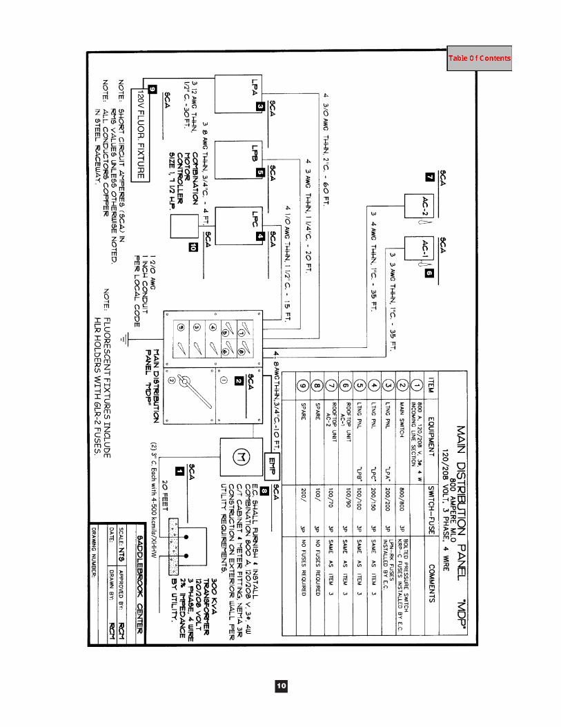
Work Sheet Problem—Main Distribution Panel
PRIMARY FUSE
Ground Bus-2/0 AWG
300 KVA Transformer by Utility120/208 Volt, 3 Phase, 4 Wire2% Impedance
(2) 3" C. Each with 4 - 500 kcmils/XHHN - 20 Feet
4 - 8 AWG THHN, 3/4"C. - 10 Feet
METER
MAIN SWITCH
800/800
200/200
200/150
100/100
100/90
100/70
100/
200/
4 - 3/0 AWG THHN, 2" C. - 60 Feet
4 - 1/0 AWG THHN, 1-1/2" C. - 15 Feet
4 - 3 AWG THHN, 1-1/4" C. - 20 Feet
3 - 3 AWG THHN, 1" C. - 35 Feet
3 - 4 AWG THHN, 1" C. - 35 Feet
LPA
LPC
LPB
AC-1
AC-2
3
1
2
4
5
6
7
8
9
EMP
120V
FLU
OR
.
FIXT
UR
E
3-1
2 A
WG
TH
HN
3-8
AW
G T
HH
N,3
/4"
C.-
4 F
eet
Combination Motor
Controller
1/2"
C.-
30'
7-1/2
1
2
3
4
5
6
7
8
9
10
Note: Assume steel conduit.

Electrical Plan Review
Short-Circuit Calculations - Worksheet
(1) Transformer (Secondary Terminals – Assuming Infinite Primary)Find: Transformer Full-Load Amperes - IFLA (3 Phase):IFLA =
Find: Multiplier – “M”M = Calculate: Short-Circuit Current (SCA)
SCA = SCA with voltage variance = Motor Contribution* = * Note: Calculate additional motor short-circuit contribution. Assume 50% (400A) of the total load is from all motors. Multiplytotal motor FLA by 4 (400 x 4 = 1,600A). In theory, the additional motor short-circuit contribution should be calculated at allpoints in the system, and may vary depending upon the location.
SCA with voltage variance and motor contribution =
(2) MDPShort-Circuit Current at beginning of run (Transformer Secondary Terminals with voltage variance) = _____________________Find: “f” factorf =
Find: Multiplier - “M”M = Calculate: Short-Circuit Current (SCA)SCA with voltage variance = Motor Contribution =SCA with voltage variance and motor contribution =
(3) LPAShort-Circuit Current at beginning of run (MDP with voltage variance) = _______________Find: “f” factorf =
Find: Multiplier - “M”M = Calculate: Short-Circuit Current (SCA)SCA with voltage variance =Motor Contribution =SCA with voltage variance and motor contribution =
(4) LPCShort-Circuit Current at beginning of run (MDP with voltage variance) = _______________Find: “f” factorf =
Find: Multiplier - “M”M = Calculate: Short-Circuit Current (SCA)SCA with voltage variance =Motor Contribution =SCA with voltage variance and motor contribution =
12

Electrical Plan Review
Short-Circuit Calculations - Worksheet
(5) LPB
Short-Circuit Current at beginning of run (MDP with voltage variance) = ________________
Find: “f” factor
f =
Find: Multiplier - “M”
M =
Calculate: Short-Circuit Current (SCA)
SCA with voltage variance =
Motor Contribution =
SCA with voltage variance and motor contribution =
(6) AC-1
Short-Circuit Current at beginning of run (MDP with voltage variance) = ________________
Find: “f” factor
f =
Find: Multiplier - “M”
M =
Calculate: Short-Circuit Current (SCA)
SCA with voltage variance =
Motor Contribution =
SCA with voltage variance and motor contribution =
(7) AC-2
Short-Circuit Current at beginning of run (MDP with voltage variance) = ________________
Find: “f” factor
f =
Find: Multiplier - “M”
M =
Calculate: Short-Circuit Current (SCA)
SCA with voltage variance =
Motor Contribution =
SCA with voltage variance and motor contribution =
13

Electrical Plan Review
Short-Circuit Calculations - Worksheet
(8) EMP
Short-Circuit Current at beginning of run (MDP with voltage variance) = ________________
Find: “f” factor
f =
Find: Multiplier - “M”
M =
Calculate: Short-Circuit Current (SCA)
SCA with voltage variance =
Motor Contribution =
SCA with voltage variance and motor contribution =
(9) Fluorescent Fixture
Short-Circuit Current at beginning of run (LPA with voltage variance) = ________________
Find: “f” factor
f =
Find: Multiplier - “M”
M =
Calculate: Short-Circuit Current (SCA)
SCA with voltage variance =
*Ignore motor contribution for this step
(10) Combination Motor Controller
Short-Circuit Current at beginning of run (LPC with voltage variance) = ________________
Find: “f” factor
f =
Find: Multiplier - “M”
M =
Calculate: Short-Circuit Current (SCA)
SCA with voltage variance =
Motor Contribution =
SCA with voltage variance and motor contribution =
14