Shock-Induced Phase Transformation in Tantalum
14
LLNL-JRNL-443671 Shock-Induced Phase Transformation in Tantalum L. L. Hsiung July 20, 2010 Journal of Physics: Condensed Matter
Transcript of Shock-Induced Phase Transformation in Tantalum

LLNL-JRNL-443671
Shock-Induced PhaseTransformation in Tantalum
L. L. Hsiung
July 20, 2010
Journal of Physics: Condensed Matter

Disclaimer
This document was prepared as an account of work sponsored by an agency of the United States government. Neither the United States government nor Lawrence Livermore National Security, LLC, nor any of their employees makes any warranty, expressed or implied, or assumes any legal liability or responsibility for the accuracy, completeness, or usefulness of any information, apparatus, product, or process disclosed, or represents that its use would not infringe privately owned rights. Reference herein to any specific commercial product, process, or service by trade name, trademark, manufacturer, or otherwise does not necessarily constitute or imply its endorsement, recommendation, or favoring by the United States government or Lawrence Livermore National Security, LLC. The views and opinions of authors expressed herein do not necessarily state or reflect those of the United States government or Lawrence Livermore National Security, LLC, and shall not be used for advertising or product endorsement purposes.

* Corresponding author. Tel.: +1-925 424 3125; fax: +1-925 424 3815 E-mail address: [email protected]
Shock-Induced Phase Transformation in Tantalum
Luke L. Hsiung*
Lawrence Livermore National Laboratory
Physical and Life Sciences Directorate
P. O. Box 808, L-352
Livermore, CA 94551-9900
Abstract - A TEM study of pure tantalum and tantalum-tungsten alloys explosively shocked at a
peak pressure of 30 GPa is presented. While no omega phase was found in shock-recovered pure Ta
and Ta-5W that contain mainly a cellular dislocation structure, shock-induced omega phase was
found in Ta-10W that contains evenly-distributed dislocations with a density higher than 1 x 10¹²
cm-2. The shock-induced α (bcc) → ω (hexagonal) transition occurs when dynamic recovery of
dislocations become largely suppressed in Ta-10W shocked under dynamic pressure conditions. A
dislocation-based mechanism is proposed for the shock-induced phase transformation.
Keyword: Shock-induced phase transformation
1. Introduction
Previous TEM studies of deformation substructures developed in tantalum and tantalum-tungsten
alloys shocked at a peak pressure 45 GPa have revealed the occurrence of shock-induced phase
transformation [i.e., α (bcc) → ω (hexagonal) transition] in addition to shock-induced deformation
twinning [1, 2]. The volume fraction of twins and ω phase-domains increases with increasing
content of tungsten. A controversy arises since tantalum exhibits no clear equilibrium solid-state
phase transformation under hydrostatic pressures up to 174 GPa [3-5]. It is known that phase
stability of a material system under different temperatures and pressures is determined by system
free energy. That is, a structural phase that has the lowest free energy is stable. For pressure-
induced phase transformation under hydrostatic-pressure conditions, tantalum may undergo phase
transition when the free energy of a competing phase, say ω, becomes smaller than that of the parent

phase (α) above a critical pressure (Peq), i.e., the equilibrium α (bcc) → ω (hexagonal) transition
occurs when the pressure increases above Peq. However, it is also known that material shocked
under dynamic-pressure conditions can lead to a considerable increase in temperature, and the higher
the applied pressure the higher the overheat temperature. This means a higher pressure is required to
achieve an equivalent volume (or density) in dynamic-pressure conditions than in hydrostatic-
pressure conditions. Accordingly, Peq for α (bcc) → ω (hexagonal) transition is anticipated to
increase under dynamic-pressure conditions as a result of the temperature effect. Although no clear
equilibrium transition pressure under hydrostatic-pressure conditions is reported for tantalum [3-5], it
is reasonable to assume that Peq under dynamic-pressure conditions will be considerably higher than
that under hydrostatic-pressure conditions if there is a pressure-induced α (bcc) → ω (hexagonal)
transition in tantalum. The observation of α (bcc) → ω (hexagonal) transition in shock-compressed
tantalum and tantalum-tungsten alloys at 45 GPa in fact reveals the occurrence of a non-equilibrium
phase transformation at such a low pressure. It is therefore postulated that the equation of state
(EOS) based on static thermodynamics, which asserts that the system free energy (G) is a function of
volume (V), pressure (P), and temperature (T), i.e., G = F(V, P, T) is insufficient to rationalize the
system free energy under dynamic-pressure, i.e., high strain-rate and high pressure, conditions.
Since shear deformation was found to play a crucial role in shock-induced deformation twins and ω
phase, density and arrangement of dislocations, which can alter and increase the system free energy,
shall also be taken into account to rationalize the phase transformation in shocked tantalum and
tantalum-tungsten alloys.
Typical arrangements of dislocations formed in pure tantalum shocked at 45 GPa (a result of
the previous experiment [1, 2]) are shown in Figs. 1a and 1b. Figure 1a reveals a cellular
dislocation structure but neither twin nor ω phase-domain was observed in this region (grain). The
formation of a cellular dislocation structure, which contains cell walls associated with a low-
density dislocation structure within the cells, indicates the occurrence of dynamic-recovery
reactions. Note that dynamic-recovery reactions usually involve the following two reactions: (1)
the mutual annihilation of dislocations with the same Burger’s vector of opposite sign (± b) and (2)
the interaction of dislocations with different Burger’s vectors (b1 and b2) to form a “junction”
dislocation (b3), i.e., b1 + b2 → b3. Both reactions can lead to a decrease in dislocation density.
Figure 1b shows a high-density and evenly distributed dislocation structure observed in a different
region (grain) of the shock-recovered pure Ta. In addition, shock-induced twin plates and ω

phase-domains can be readily seen. A dislocation density (ρ) on the order of ~5 x 1012 cm-2 was
measured according to ρ = 1/l2, where l (~4.5 nm) is the mean spacing between dislocations. Note
that the dislocation density is defined by the total length of the dislocation lines per unit volume; it
has the dimension: cm/cm3 = 1/cm2. If all dislocations are straight and parallel, the dislocation
density ρ is related the dislocation spacing by ρ = 1/l2. The above observations provide us a clue
that dislocation arrangement and density population, which can alter system free energy through
the changes of dislocation self-energy (Es) and dislocation interaction energy (Eij), are relevant to
the occurrence of shock-induced twinning and phase transformation in tantalum. Twinning and
phase transformation occur when dynamic-recovery reactions are largely suppressed in pure Ta
and Ta-W alloys shocked at 45 GPa. The objectives of this paper are (1) to report new results
obtained from pure tantalum and tantalum-tungsten alloys shocked at a peak pressure of 30 GPa in
order to compare with the results of previous shock-recovery experiment conducted at 45 GPa and
(2) to clarify the correlation between dislocation structure (i.e., density and arrangement) and
shock-induced α (bcc) → ω (hexagonal) transition.
2. Experimental
Ingot metallurgy (IM) test materials (commercially pure Ta, Ta-5wt.%W, and Ta-10 wt.%W) in
the form of plate stock produced using a standard electron-beam melting process were obtained from
Cabot Corporation, Boyertown, PA. Details of explosively driven shock-recovery experiment
used for this investigation can be found in [6]. Single explosively driven shock-recovery
experiments were conducted by detonating explosive on hemisphere-shaped alloy plates (3mm thick)
that were shocked into polyurethane foams immersed in a water tank. The shock experiments were
carried out under a peak pressure of 30 GPa simulated using a CALE continuum hydrodynamic code
[7]. Thin foils for TEM characterization were prepared by a standard procedure that includes slicing,
grinding, and polishing the recovered fragments with the foils surface approximately perpendicular
to the loading axis. Final thinning of the foils was performed using a standard twin-jet
electropolishing technique in an electrolyte (94 vol.% methanol, 5 vol.% sulfuric acid and 1 vol.%
hydrofluoric acid) at 25 V and -20 C. The microstructures of shock-recovered fragments were then
characterized using a JEOL 200CX transmission electron microscope (TEM). A software package
“CaRIne Crystallography 3.1” was employed to simulate diffraction patterns in order to identify the
shock-induced ω phase.

3. Results and Discussion
3.1 TEM charactrization
Figures 2a and 2b are bright-field (BF) TEM images showing that cellular dislocation structures
were observed in shock-recovered pure Ta and Ta-5W samples. In addition, twins and ω phase-
domains, as observed in pure Ta shocked at 45 GPa (Fig. 1b), were not found in pure Ta and Ta-5W
shocked at 30 GPa. Figure 2c however shows that the dislocation structure formed in Ta-10W
shocked at the same pressure is very different. Here the dislocation lines formed in shocked Ta-10W
are much denser and evenly distributed, which are very similar to those observed in Fig. 1b (pure-Ta
shocked at 45 GPa). Furthermore, some small ω particles and platelets embedded in the high-density
dislocation lines can be readily seen. Notice that they appear as bright particles and platelets in the
dark-field (DF) image obtained using the circled diffraction spot of the [1010]ω-zone pattern shown in
Fig. 2c. Details on the identification of omega phase will be further discussed later. The local
dislocation density in Fig. 2d is measured to be on the order of 2 x 1012 cm-2 according to ρ = 1/l2,
where l (~6 nm) is the mean spacing between dislocations. Since the major effect of W addition is to
impede dislocation motion, i.e., to reduce the dislocation mobility to strengthen tantalum, these
observations suggest that the dynamic-recovery reactions for the formation of cellular dislocation
structure are largely suppressed in Ta-10W as a result of the decrease in dislocation mobility, which
can be rationalized according to the Orowan equation: Φ , where Φ is the
average Schmid factor (~0.327), b is the magnitude of Burger’s vector (0.286 nm), ρ is the mobile
dislocation density, and is the average dislocation velocity. Since Φ are constants, the strain
rate is solely accommodated by , i.e., dislocation flux. That is, under a given strain rate ( , the
mobile dislocation density ( must increase when the average dislocation velocity ( decreases as a
result of the decrease in dislocation mobility due to the W addition. Consequently, more dislocations
have to be nucleated to balance the decrease in dislocation velocity, which in turn leads to a shorter
travel distance for each dislocation and thus results in the suppression of dynamic-recovery reactions
in shocked Ta-10W.
3.2 Identification of shock-induced ω phase
It is known that the ω (hexagonal)-lattice can be perceived by collapsing one pair of (111) planes
within the α (Ta, bcc)-lattice and leaving the adjacent (111) planes unaltered [8]. Note that this

collapse model was originally proposed to explain the β (bcc) → ω (hexagonal) transition in group
IV transition metals (titanium, zirconium, and hafnium), which have an hcp (α) structure at room
temperature but transform to a bcc (β) structure at high temperatures. The atomic displacements
required are ± ao 3 /12, where ao is the lattice parameter of α (Ta, bcc)-lattice. It contains 3-
atoms/unit cell with the lattice constants: aω = 2 ao = 0.468 nm and cω = ( 3 /2) ao = 0.286 nm
(cω/aω = 0.611). There is no volume change associated with this transformation. The atomic
positions are a: (0,0,0); b: (2/3,1/3,1/2); c: (1/3,2/3,1/2). However, when we carefully examined the
atomic positions of the hexagonal lattice, we find that the distance (0.27 nm) is too short to
accommodate atoms b and c with the atomic diameter equivalent to cω (0.286 nm), as shown in Fig.
3a. These two atoms have to shuffle slightly to increase the distance to ~0.302 nm, as shown in Fig.
3b. The atomic shuffling does not alter the lattice constants but results in a pseudo-hexagonal
structure due to the loss of six-fold symmetry. The atomic positions of the pseudo-hexagonal lattice
thus become a: (0,0,0); b: (0.685, 0.315, 0.5); c: (0.315, 0.685, 0.5). The existence of ω phase in
shock-recovered Ta-10W was accordingly identified by matching and comparing the observed and
simulated diffraction patterns of the ω phase with a pseudo-hexagonal structure, as demonstrated in
Fig. 4. Here the formation of ω phase can be easily recognized from the appearance of extra spots
excited at various 1/3<112>α and 2/3<112>α positions in the [011]α-, [012]α-, and [113]α-zone
diffraction patterns, in which the simulated [11 2 0]-, [11 2 6]-, and [11 2 3]-zone patterns of ideal-
hexagonal ω and pseudo-hexagonal ω are also displayed in Fig. 4. The simulated diffraction
patterns of the pseudo-hexagonal structure match very well with the observed diffraction patterns.
These results confirm that the crystal structure of shock-induced ω phase is not ideal-hexagonal but
pseudo-hexagonal as illustrated and explained in Fig. 3b.
3.3 A proposed mechanism for the shock-induced phase transformation
A bcc structure can be constructed by stacking the {211} planes with a sequence of A B C D E F,
i.e., the six different positions of atom layers projected normal to the {211} planes. Similar to the
shear mechanism for deformation twinning, i.e., homogeneous 1/6<111> shear in the consecutive
{211}α planes, the α (bcc) → ω (hexagonal) transition can take place through the inhomogeneous
shear of 1/12<111>, 1/3<111>, and 1/12<111> in three consecutive {211}α planes, as illustrated in
Fig. 5, which change the bcc stacking sequence through…A B [C → C′] [D→ D′→ F′] [E→ E′→

A′→ E] F to the omega stacking sequence …A B C′ F′ E F. That is, as shown in Fig. 5a, the atoms
of C move 0.5/6<111> to C′ ; the atoms of D (on top of C ) move 0.5/6<111> to D′ and then move
another 2/6<111> to F′; the atoms of E (on top of D) move 0.5/6<111> to E′ and move 2/6<111>
to A′ and move another 0.5/6<111> to E, i.e., no change on stacking. The total displacement is
0.5/6<111> for C to C´, 2.5/6<111> for D to F´, and 3/6<111> for E to E, as shown in Fig. 5b. The
orientation relationships between the α matrix and the ω phase are determined: (211)α || (1100)ω and
[111]α || [0001]ω. The stacking sequence resulting from the three-layer inhomogeneous shear is
literally equivalent to the atomic shuffling of ±1/12[111] in a pair of {211} planes for the α (bcc) →
ω (hexagonal) transition according to the collapse model illustrated in Fig. 3a. The shock-induced α
(bcc) → ω (hexagonal) transition in tantalum can thus be regarded as a diffusionless shear
transformation. The occurrence of shear transformation associated with dense and evenly
distributed dislocation structure may imply that both twinning and the α (bcc) → ω (hexagonal)
transition are alternative deformation mechanisms to accommodate insufficient dislocation flux ( )
resulting from the exhaustion of dislocation sources when dynamic recovery reactions become
largely suppressed in shocked tantalum and tantalum-tungsten alloys. Both shock pressure and
tungsten addition can have effects on reducing dislocation mobility and accordingly enhance the
suppression of dynamic-recovery reactions. When tantalum was shocked at 45 GPa, high pressure
alone can suppress the dynamic-recovery reactions and lead to shear transformation in pure Ta. The
addition of W further enhances the effect and results in a higher volume fraction of twins and ω
phase-domains [2]. When tantalum was shocked at 30 GPa, the shock-induced shear transformation
associated with dense and evenly-distributed dislocations occurred only when 10 wt.% W was added
to effectively suppress the dynamic-recovery reactions.
The shear transformation of bcc structure to twin and ω domains can be produced by the glide of
partial dislocations of the type 1/3<111>, 1/6<111> and 1/12<111> dissociated from the 1/2<111>
perfect dislocation, as shown in Fig. 6. Each 1/2<111> dislocation can dissociate into three
1/6<111> partials (each one plane apart) in the {211} plane to form a three-layered twin domain. In
other words, it requires the dissociation of two 1/2<111> dislocations with three-plane separation
(0.405 nm) to form a unit (six-layer) twin domain. Similarly, the partial dislocations for the α (bcc)
→ ω (hexagonal) transition can be obtained by the dissociation of two 1/2<111> dislocations with
six-plane separation (0.81 nm) into two 1/12<111> partials and one 1/3<111> partial (each one plane

apart) in the {211} plane to form a unit (six-layer) ω domain. These two dissociation reactions, i.e.
→ + + , are energetically feasible because the free energy is gained in the dissociation
process according to Frank’s rule [9]: b12 + b2
2 + b32 < b2.
4. Conclusions
Shock-induced α (bcc) → ω (hexagonal) transition in tantalum, which exhibit no clear solid-
state phase transformation under hydrostatic pressure conditions, was further investigated through
single explosively driven shock-recovery experiments conducted by detonating explosive on
hemisphere-shaped alloy plates to generate a peak pressure of 30 GPa. The onset of α (bcc) → ω
(hexagonal) transition is found to be intimately related to the density and arrangement of dislocation
structure. While no ω phase-domain was found in the shock-recovered pure Ta and Ta-5W samples
that contain mainly cellular dislocation structures, many ω phase-domains were observed in the
shock-recovered Ta-10W sample that contains evenly-distributed dislocations with a high dislocation
density (ρ > 1 x 1012 cm-2). It is suggested that the shock-induced α (bcc) → ω (hexagonal)
transition is an alternative deformation mechanism to accommodate insufficient dislocation flux
resulting from the exhaustion of dislocation sources when dynamic recovery reactions for dislocation
annihilation and cellular dislocation structures become largely suppressed.
Acknowledgements
This work was performed under the auspices of the U.S. Department of Energy by Lawrence
Livermore National Laboratory under Contract DE-AC52-07NA27344. The author gratefully
acknowledges Dr. J. M. McNaney (LLNL) for conducting shock-recovered experiments and Dr. B.
A. Remington (LLNL) for valuable support.
References
1. L.M. Hsiung and D.H. Lassila, Scripta Mater. 39, 603 (1998).
2. L.M. Hsiung and D.H. Lassila, Acta Mater. 48, 4851 (2000).
3. D.A. Young, Phase Diagrams of the Elements, University of California Press, Berkeley:
California (1991).
4. E. Yu Tonkov, E.G. Ponyatovsky, Phase Transformations of Elements under High Pressure,
CRC Press, 239 (2005).

5. H. Cynn, C.S. Yoo, Equation of state of tantalum to 174 GPa, Phys. Rev. B 59, 8526 (1999).
6. G.H. Campbell, G.C. Archbold, O.A. Hurricane, and P. L. Miller, J. of Appl. Phys. 101,
033540 (2007).
7. R.T. Barton, in Numerical Astrophysics, edited by J.M. Centrella, J.M. LeBlanc, and R.L.
Bowers (Jones and Bartlett, Boston 482 (1985).
8. S. K. Zikka, Y. K. Vohra, and R. Chidambaram, Progress in Materials Science 27 245 (1982).
9. J. Wertman, J.R. Wertman, Elementary Dislocation Theory, Macmillan (1964).
10. E.M. Nadgornyi, Progress in Materials Science 31, 1 (1988).

Fig. 1. Bright-field TEM images demonstrate the formation (a) a cellular dislocation structure due to dynamic recovery reactions and (b) a dense and evenly distributed dislocation structure co-exists with twins and ω phase-domains in pure Ta shocked at 45 GPa (a result of the previous experiment [1, 2]).
Fig. 2. Bright-field TEM images show the formation of cellular dislocation structures in (a) shocked pure Ta, (b) shocked Ta-5W, (c) the formation of ω phase domains embedded in dense and evenly distributed dislocations in shocked Ta-10W, and (d) a higher magnification view of the framed area in (c). The inset selected-area diffraction pattern is of the [1011]ω-zone.

Fig. 3. Schematic illustrations of (a) a collapse model for the α (bcc) → ω (hexagonal) transition [8], (b) the atomic positions of an ideal-hexagonal ω-lattice, and (c) a pseudo-hexagonal ω-lattice after atomic shuffling to accommodate b and c atoms.

Fig. 4. Selected-area diffraction patterns of (a) [011]α-, (b) [012]α-, and (c) [311]α-zone in association with weak diffraction spots generated from the shock-induced ω phase. The simulated (a) [11 2 0]-, (b) [11 2 6]-, and (c) [11 2 3]-zone diffraction patterns of ideal-hexagonal ω and pseudo-hexagonal ω are also displayed. Notice that some diffraction spots excited in the diffraction patterns of pseudo-hexagonal ω phase are forbidden in the diffraction patterns of ideal-hexagonal ω phase.
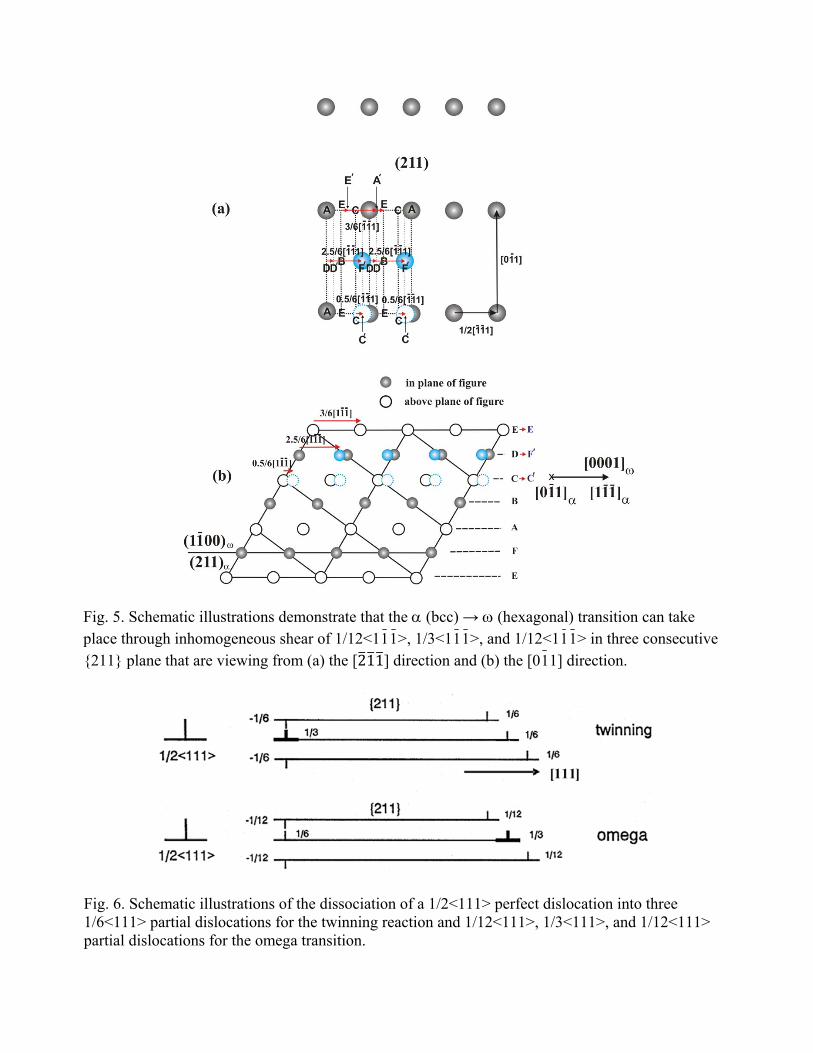
Fig. 5. Schematic illustrations demonstrate that the α (bcc) → ω (hexagonal) transition can take place through inhomogeneous shear of 1/12<111>, 1/3<111>, and 1/12<111> in three consecutive {211} plane that are viewing from (a) the [211] direction and (b) the [011] direction.
Fig. 6. Schematic illustrations of the dissociation of a 1/2<111> perfect dislocation into three 1/6<111> partial dislocations for the twinning reaction and 1/12<111>, 1/3<111>, and 1/12<111> partial dislocations for the omega transition.