Shift Registers - Milwaukee Area Technical Collegeecampus.matc.edu/lokkenr/elctec-131/pp...
37
Shift Registers ELCTEC-131
Transcript of Shift Registers - Milwaukee Area Technical Collegeecampus.matc.edu/lokkenr/elctec-131/pp...

Shift Registers
ELCTEC-131

Shift Register Terminology Shift Register: A synchronous
sequential circuit that will store and move n-bit data either serially or in parallel in a n-bit Register (FF).
Left Shift: A movement of data from right to left in the shift register (toward the MSB). One bit shift per clock pulse.
2/15/2010 2© 2009 Richard Lokken

Shift Register Terminology Right Shift: A movement of data from
left to right in the shift register (toward the LSB). One bit shift per clock pulse.
Rotation: Serial shifting (right or left) with the output of the last FF connected to the input of the first. Results in continuous circulation of SR data.
2/15/2010 3© 2009 Richard Lokken

2/15/2010 4© 2009 Richard Lokken

2/15/2010 5© 2009 Richard Lokken

Serial Shift Register (SR)
A 4-Bit Left Shift Register.
DIN is shifted into the LSB FF and shifted toward the MSB.
Q0 D0
<
DINQ1 D1
<
Q2 D2
<
Q3 D3
<CLK
LSB
MSB
2/15/2010 6© 2009 Richard Lokken

SS Left Shift
Q0 D0
<
DIN
Q1 D1
<
Q2 D2
<
Q3 D3
<
CLK
LSB
MSB
2/15/2010 7© 2009 Richard Lokken

SS Left ShiftQ0 D0
<
DIN
Q1 D1
<
Q2 D2
<
Q3 D3
<
CLK
LSB
MSB
2/15/2010 8© 2009 Richard Lokken

SS Left Shift
Q0 D0
<
DINQ1 D1
<
Q2 D2
<
Q3 D3
<
CLK
LSB
MSB
2/15/2010 9© 2009 Richard Lokken

SS Left ShiftQ0 D0
<
DINQ1 D1
<
Q2 D2
<
Q3 D3
<
CLK
LSB
MSB
2/15/2010 10© 2009 Richard Lokken

Bi-Directional Shift Register
Uses a control input signal called direction to change circuit function from shift right to shift left.
4-bit bi-directional SR is shown in Figure 9.91.
2/15/2010 11© 2009 Richard Lokken

Bi-Directional Shift Register
When DIR = 0, the path of Left_Shift_Inis selected.
When DIR = 1, it selects the Right Shift In Path.
⇒⇒⇒⇒ 0123 QQQQ
⇐⇐⇐⇐ 0123 QQQQ
2/15/2010 12© 2009 Richard Lokken
SR with Parallel Load
Similar to a Parallel Load Counter, the Shift Register is shown in Figure 9.93.
Uses a 2-to-1 Mux (AND/OR) to control inputs to the FF in the SR. The input choice is from the previous FF Output or the Parallel Input.
When Load = 1, Parallel Data is loaded in on the next clock pulse.
2/15/2010 13© 2009 Richard Lokken
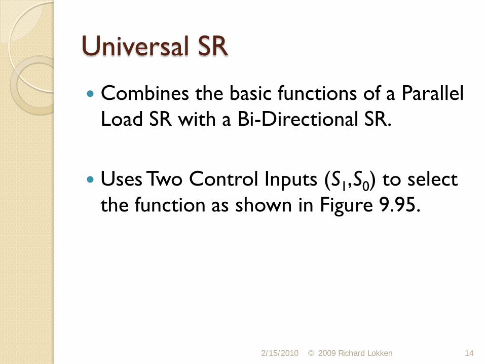
Universal SR
Combines the basic functions of a Parallel Load SR with a Bi-Directional SR.
Uses Two Control Inputs (S1,S0) to select the function as shown in Figure 9.95.
2/15/2010 14© 2009 Richard Lokken

Universal SR
2/15/2010 15© 2009 Richard Lokken

Universal SR Truth Table (S1/S0)
Function0 0 Hold Q 3 Q 2 Q 1 Q 0
0 1 Shif t Left RSI * Q 3 Q 2 Q 1
1 0 Shif t Right Q 2 Q 1 Q 0 LSI **1 1 Load P 3 P 2 P 1 P 0
S 1 S 0 D 3 D 2 D 1 D 0
* RSI = Right-Shif t Input / ** LSI = Left-Shif t Input
2/15/2010 16© 2009 Richard Lokken

Structured VHDL SR Structured VHDL Design: A VHDL design
technique that connects predesigned components using internal signals.
Would use DFF primitives to construct different types such as LSR and RSR.
A DFF Primitive Port Map is (D, CLK, Q).
2/15/2010 17© 2009 Richard Lokken

LIBRARY ieee;
USE ieee.std_logic_1164.ALL;
LIBRARY altera;
USE altera.maxplus2.ALL;
-- Note: IEEE is before Altera declarations
-- maxplus2 is for the primitive DFF Design
VHDL SR Entity
Basic Entity for a Structural RSR Design
2/15/2010 18© 2009 Richard Lokken
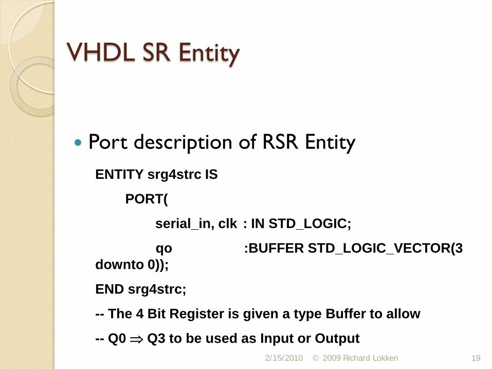
ENTITY srg4strc IS
PORT(
serial_in, clk : IN STD_LOGIC;
qo :BUFFER STD_LOGIC_VECTOR(3 downto 0));
END srg4strc;
-- The 4 Bit Register is given a type Buffer to allow
-- Q0 ⇒ Q3 to be used as Input or Output
VHDL SR Entity
Port description of RSR Entity
2/15/2010 19© 2009 Richard Lokken

ARCHITECTURE right_shift OF srg4strc IS
COMPONENT DFF
PORT ( d : IN STD_LOGIC;
clk : IN STD_LOGIC;
q : OUT STD_LOGIC);
END COMPONENT;
VHDL SR Component Description
Structural Architecture Component DFF
2/15/2010 20© 2009 Richard Lokken

BEGIN
flipflop3: dff
PORT MAP (serial_in, clk, qo(3) );
dffs:
FOR i IN 2 downto 0 GENERATE
flip_flops_2_ to_0: dff
PORT MAP (qo(i + 1), clk, qo(i) );
END GENERATE;
END right_shift;
VHDL RSR Architecture
2/15/2010 21© 2009 Richard Lokken

Structured Architecture Example
Four dff components are mapped to create a RSR, serial_in is to Q3 and shift is toward Q0.
Uses a FOR GENERATE Loop to create and map the four dff (Flip Flops).
2/15/2010 © 2009 Richard Lokken 22
DataFlow Design Approach DataFlow Design: A VHDL design approach
that uses Boolean Equations to define relationships between inputs and outputs.
The Entity is the same as the Structured approach, except the Altera Library is not needed.
The register q is still declared as a Buffer.
2/15/2010 23© 2009 Richard Lokken

ARCHITECTURE right_shift OF srg4dflw IS
SIGNAL d : STD_LOGIC_VECTOR (3 downto 0);
BEGIN
PROCESS(clk)
BEGIN
IF clk’ EVENT AND clk = ‘1’ THEN
q <= d;
END IF;
VHDL Dataflow RSR
Basic Process Type of Architecture
2/15/2010 © 2009 Richard Lokken 24

END PROCESS;
d <= serial_in & q(3 downto 1);
END right_shift;
-- The actual data flows on d(0 - 3) outside the process.
-- d(0-3) uses the Concatenate Operator (&) to create
-- the four bit RSR. The process and d assignment are
-- both executed concurrently.
VHDL DataFlow RSR
Continuation of RSR Architecture
2/15/2010 © 2009 Richard Lokken 25

PROCESS(clk, clear)
BEGIN
IF clear = ‘0’ THEN
q <= (others => ‘0’); -- asynchronous clear
ELSEIF (clk’EVENT and clk = ‘1’) THEN
Bi-Directional SR VHDL
Adds a basic direction control to the dataflow architecture given earlier.
2/15/2010 © 2009 Richard Lokken 26

CASE direction IS
WHEN ‘0’ => q <= q(2 downto 0) & lsi; -- Left Shift
WHEN ‘1’ => q <= rsi & q(3 downto 1); -- Right Shift
WHEN OTHERS => Null;
END CASE;
END IF;
END PROCESS;
END bidirectional_shift;
Bi-Directional SR VHDL
VHDL Architecture Continued
2/15/2010 © 2009 Richard Lokken 27

Generic Width Shift Register
Uses a VHDL Generic Clause in the Entity to specify a Width Variable. General form is GENERIC
◦ (Clause := Value)
For a 4-Bit SR we use GENERIC.
◦ (Width : Positive := 4).
2/15/2010 © 2009 Richard Lokken 28

ENTITY srt_bhv IS
GENERIC (Width : POSITIVE := 4);
PORT (
serial_in, clk :IN STD_LOGIC;
q : BUFFER STD_LOGIC_VECTOR (width-1 downto 0));
END srt_bhv;
Generic VHDL File Entity
Width set to 4 Bits
2/15/2010 © 2009 Richard Lokken 29

ARCHTITECTURE right_shift of srt_bhv IS
BEGIN
PROCESS(clk)
BEGIN
IF(clk’EVENT AND clk = ‘1’) THEN
q(width-1 downto 0) <= serial_in & q(width-1 downto 1);
END IF;
END PROCESS;
END right_shift;
Generic VHDL Architecture
2/15/2010 30© 2009 Richard Lokken

Shift Register Counters
Two types: Ring and Johnson
Ring Counter: A serial Shift Register with feedback from the output of the last FF to the input of the first FF.
Counter sequences are based on a continuous rotation of data through the SR.
2/15/2010 31© 2009 Richard Lokken

Ring Counters A basic Ring Counter (Figure 9.102) is
constructed of D-FF with a Feedback Loop.
Data is initially loaded into the SR by using either Resets or Presets.
The counter can circulate a 0 or 1 by loading a 1000 or 0111.
2/15/2010 32© 2009 Richard Lokken

Ring Counters The Modulus of a Ring Counter is defined
as the maximum number of unique states.
Modulus is dependent on the initial load value {1000, 0100, 0010, 0001} = Mod4 while {1010, 0101} = Mod2.
Typically an N-FF Ring Counter has N-States, not 2N like a binary counter.
2/15/2010 33© 2009 Richard Lokken

Johnson Counters
Johnson Counter: A serial shift register with the complemented feedback from the output of the last FF to the input of the first FF.
Same as the Ring Counter sequences based on a continuous rotation of data through the SR.
2/15/2010 34© 2009 Richard Lokken

Johnson Counters Same as a Ring (Figure 9.106) except that
(Complement) is fed back to D3, not to Q0.
Adds a complement or “twist” to the data and is called a Twisted Ring Counter.
Usually Initialized with 0000 by a Clear.
2/15/2010 © 2009 Richard Lokken 35
0Q

Johnson Counters Typically has more states than a ring
counter.
Sequence of states = {0000, 1000, 1100, 1110, 1111, 0111, 0011, 0001}.
Maximum Modulus is 2n for a circuit with n flip-flops.
2/15/2010 36© 2009 Richard Lokken

Experiment 26
Serial Shift Register from Flip-Flops
◦ Simulate◦ Program DE1 board and Test
Universal Shift Register (VHDL)
◦ Simulate◦ Program DE1 board and Test
2/15/2010 © 2009 Richard Lokken 37