TSUBAME-KFC: 液浸冷却を用いた ウルトラグリー …TSUBAME-KFC: 液浸冷却を用いた ウルトラグリーンスパコン研究設備 遠藤敏夫、額田彰、松岡聡

Shell & Tube Cooler管式冷却器Installation and servicing manual安装和服务手册
aerospaceclimate controlelectromechanicalfiltrationfluid & gas handlinghydraulicspneumaticsprocess controlsealing & shielding

Installation and servicing manualShell & Tube Cooler
2 Parker Hannifin CorporationHydraulics Group
Catalogue HY10-6014-UM/CN

Installation and servicing manualShell & Tube Cooler
3 Parker Hannifin CorporationHydraulics Group
Catalogue HY10-6014-UM/CN
Contents
Introduction & Directions 41. Safety Notice 42. Product Overview 53. Product Parts Name 64. Installation 65. Preventive Maintenance 86. Maintenance Procedures 87. Emergency Measures 108. Warranty Repair & Regional Service Network 10Annex 11
前言 & 安全指示 131. 安全注意事项 132. 产品简介 143. 产品部件名称 154. 安装 155. 定期维护保养 176. 维护流程 177. 应急措施 188. 保质期内维修和区域客服 网络 19附件 19
CN
GB

Installation and servicing manualShell & Tube Cooler
4 Parker Hannifin CorporationHydraulics Group
Catalogue HY10-6014-UM/CN
Introduction/Directions/Safety Notice
IntroductionThank you for using our Shell & Tube Cooler.This Manual explains how to use and maintain the shell and tube cooler correctly and safely. In addition, it provides the information on important safety issue and simple maintenance techniques.Please read this manual carefully and ensure it is understood so as to use this shell and tube cooler properly.If the product is not functioning properly, please contact a regional company distributor or our headquaters directly for appropriate services.
DirectionsThis manual provides safety direction with the following labels: Please read carefully and follow the instructions. This symbol means possible danger. Failure to follow instructions could result in death and or serious personal injury.
This symbol means possible danger. Failure to follow instructions could cause part or full damage to the product and or other property.
This symbol indicates that instructions are given for the shell and tube operation and maintenance.
1. Safety Notice
1.1 General Safety Notes
To help with the effective use of the shell and tube cooler and for safety, this manual provides a product overview along with
information on installation, operation, maintenance, and solutions for emergency. Please read it carefully prior to use coolers.
Please read and ensure you understand these instructions carefully prior to use the product.Please ensure that you read the entire manual prior to use the shell and tube cooler and associated hydraulic system.
• DO NOT use this product for any other purpose than heat exchanging.
• DO NOT use any inappropriate liquids that may cause a harmful chemical reaction and/or corrosion on product material.
• DO NOT use this product under working conditions that are out of the shell and tube installation and servicing manual scope.
1.2 Important Safety Notes
1.2.1 CAUTION
This symbol point outs general safety notice.
1.2.2 OPERATOR MANUAL
Read carefully and ensure that you understand the product prior to use it. Faillure to follow the operating manual could result in death and/or serious injury.
1.2.3 DANGER DUE TO HOT SURFACE
Hot Surface may cause burns. Please ensure that you cool down the product and wear protective gloves before touching it.
1.2.4 DANGER DUE TO LIQUID SPRAY
Wear protective gear to prevent any danger caused by harmful liquid spray from a pressurized device.
Disassembling the product when the Oil Inlet Line is pressurized may cause injury due to the harmful oil spray. Ensure that you remove the internal and external pressure of the product
and wear protective clothing. Then proceed to the shell and tube disassembly in accordance with maintenance procedures of this manual.
1.2.5 TECHNICAL MANUAL
Consult the technical manual prior to servicing.
Follow the installation and servicing manual instructions when disassembling and/or replacing any parts. The manufacturer is not
responsible for any damages to products and/or user property caused by disassembling the coolers in a manner other than one described in the instructions.
1.3 After Purchase
Ensure that you check the following items after purchasing the product.
1.3.1 PRODUCT SPECS
Check that dimensions, Part Number and connection port specifications of the product are correct and as ordered.
1.3.2 PRODUCT APPEARANCE
Inspect the shell and tube cooler and make sure that it is free of any damage.
1.4 Prior to installation
1.4.1 WORKING LIQUID: OIL & WATER
OIL: Prevent any possible chemical reaction and corrosion of copper pipe with finned aluminum and steel pipe by using the most generally used Hydraulic Oil. Inappropriate fluid (corrosive oil, dirty oil, other
fluids) will result in material deterioration and safety risks.
Water: The water must be clear, colorless and odorless as well as free from algae, germs, fungi, bacteria, iron, manganese, hydrogen, floating matters, suspended substances and sediments. For clean
cooling water standards, refer to the recommendation table at the end of this manual.

Installation and servicing manualShell & Tube Cooler
5 Parker Hannifin CorporationHydraulics Group
Catalogue HY10-6014-UM/CN
2.3 Manufacturer Registration
PARKER OLAER SUzHOU (OILTECH HYDRAULICS)No. 2 workshop | #95 Weixin Road | Weiting | Suzhou Jiangsu | P.R. China 215121Tel: +86 512 6289 1000 | Fax: +86 6289 0805
Product Overview
2. Product Overview
2.1 Product Overview
The Shell & Tube Cooler is a product which keeps ideal temperature for optimum oil viscosity index in the hydraulic system. Maintaining an appropriate oil viscosity index in the hydraulic systems extends the life cyle of the valves, pumps, and parts in the system, thereby reducing maintenance costs of the system.
The Shell & Tube Cooler will provide solutions to help your hydraulic systems to operate under optimum conditions with a number of different models.
2.2 Standard Dimensions
Model A B C D E F G H I J K L M N Weight(kg)
OST-S6-4-400 ¾” ¾” 455 400 290 55 150 75 250 75 174.5 100 170 9 13
OST-S6-4-530 ¾” 589 530 420 55 150 140 250 140 174.5 100 170 9 15
OST-S6-5-680 1” 733 680 570 55 164 162 318 200 225.5 130 180 9 27
OST-S6-8-670 2” 753 670 530 70 244 173 326 171 287.5 160 270 14 50
OST-S6-8-700 2” 2” 783 700 560 70 244 158 326 216 287.5 160 270 14 53

Installation and servicing manualShell & Tube Cooler
6 Parker Hannifin CorporationHydraulics Group
Catalogue HY10-6014-UM/CN
Product Parts Name/Installation
3. Product Parts Name
4. Installation4.1 Before Installation
Heat exchanger performance, lifetime and freedom from operating difficulties are largely depending on:
1. Proper thermal design2. Proper physical design3. Manner of installation, including design of foundation
and piping.4. The method of operation5. The thoroughness and frequency of cleaning.6. The materials, workmanship, and tools used in
maintenance and making repairs and replacements.
The heat exchange effect of Shell & Tube Oil Cooler is maximized when it is installed horizontally or vertically. When the equipment is installed vertically, the anchor bolt and clamping band may be loosened due to system shock or other external reasons. Ensure that you inspect periodically to prevent any damage to your property or to the product.
FAILURE TO PREFORM PROPERLY MAY BE DUE TO ONE OR MORE OF THE FOLLOWINGS:1. Exchanger being dirty.2. Operating conditions being different than
design conditions.
4.2 Installation DirectionsEnsure that you check the safety instructions accompanying the product when handling, moving, and/or installing it.
Cooler, when installed vertically, should be installed with water draining plugs facing down (WATER INLET and OUTLET facing up).
The shell and tube cooler may easily be dropped, and damaged, when being moved for installation or repair. Ensure that you use a carrier or other assistance while moving. To maximize durability and heat exchange effect of the Shell & Tube Type Cooler, ensure that the cooler is installed on the return line, just before the tank, in order to avoid pressure peaks.
Refer to cooler specifications and use required connection type of each model.
No. Qty. Part Name Material No. Qty. Part Name Material
1 1 Floating Cover Cast Iron 9 1 Plug M14x1,5 with sealring Steel
2 1 Stationary Cover Cast Iron 10 1 “Oil Inlet” Sticker (red) Plastic
3 1 Shell Alumunium 11 1 “Oil Outlet” Sticker (red) Plastic
4 1Tube Bundle
Tubes: CopperFins AluminiumTube Sheets: Steel
12 1 “Water inlet” sticker (blue) Plastic
13 1 “Water outlet” sticker (blue) Plastic
5 1 Gasket - Floating NBR 14 1 Name Plate Aluminium
6 1 Gasket - Stationary NBR 15 16 Washer Steel FzB
7 2 O-ring NBR 16 16 Spring Washer Steel FzB
8 1 Plug M14x1,5 with sealring Stainless Steel 17 16 Hex socket head Steel FzB

Installation and servicing manualShell & Tube Cooler
7 Parker Hannifin CorporationHydraulics Group
Catalogue HY10-6014-UM/CN
Installation
4.3 Installation Conditions & Environment
4.3.1 WORKING PRESSURE
The design pressure of this product is 15 bar for oil side and 10 bar for water side. Ensure that the working pressure and surge pressure do not exceed 22 bar for oil side and 15 bar for water side, and check the working pressure of your system prior to use.
4.3.2 WORKING TEMPERATURE
Working temperature range: 0°C to 100°C.Prevent the Shell and Tube from bursting in winter by draining the cooling water in the cooler when stopping the system temporarily. (See Cooler draining on Page 7).
4.3.3 INSTALLATION ENvIRONMENT
Use cooling water in accordance with annex WATER QUALITY CRITERIA AND STANDARDS. Installation in hot and humid places may cause rust on the external surface. Prevent rusting by using paint and/or other protective measures.
4.3.4 INSTALLATION PLANNING
1. On removable bundle heat exchangers provide sufficient clearance at the stationary end to permit the removal of the tube bundle from the shell. On the floating head end, provide space to permit removal of the shell cover and floating head cover.
2. Provide valves and bypasses in the piping system so that both the shell side and tube side may be bypassed to permit isolation of the heat exchanger for inspection, cleaning and repairs.
3. Provide thermometer wells and pressure gauge Pipe taps in all piping to and from the Heat exchanger, located as close to the heat exchange as possible.
4. Provide necessary air vent valves for the heat exchanger so that it can be purged to prevent or relieve vapor or gas binding on either the tube side or shell side.
5. Provide adequate supports for mounting the heat exchanger so that it will not settle and cause piping strains. Foundation bolts should be set accurately.
6. Proper liquid level controls and relief valves and liquid level and temperature alarms, etc, should be installed.
4.3.5 INSTALLATION AT JOBSITE
Dress properly for the job. You may need any number of special items (safety hat, safety shoes, goggles, heavy gloves, ear protective devices, etc, for your own protection). Find out what items are required and
wear them!
1. On receipt of the heat exchanger at the jobsite, inspect for shipping damage to all protective covers. If damage is evident, inspect for possible contamination and replace protective covers if required. If damage is extensive, notify the carrier immediatly.
2. Store under cover in heated aread, if possible.3. If the heat exchanger must be stored for a period
exceeding 30 days, pre-cautions should be taken to prevent rusting or contamination. Following extended storage, it is suggested that the exchanger be thoroughly inspected prior to installation.
4. When installing, set heat exchanger so that pipe connections can be made without forcing.
5. Before piping up, inspect all opening in the heat exchanger for foreign material. Remove all plastic protections immediately prior to installing. Do not expose internal passages of the heat exchanger to the atmosphere since moisture or harmful contaminants may enter the unit.
6. Connect the shell and tube cooler to the hydraulic system.

Installation and servicing manualShell & Tube Cooler
8 Parker Hannifin CorporationHydraulics Group
Catalogue HY10-6014-UM/CN
Preventive Maintenance/Procedures
4.4 Before Operation
4.4.1 PIPE INSTALLATION CHECKUP
Ensure that the pipe is installed properly prior to operating the equipment. Oil and cooling water may leak when the pipe is not installed properly.
4.4.2 COOLING WATER SUPPLY
Check that the cooling water is being supplied prior to use. No heat exchanger effect will take place if the cooling water is not supplied. See PRIOR TO INSTALLATION for cooling water quality.
4.4.3 DRAIN PLUG
Ensure that water and oil drain plugs at the bottom are closed prior to operating.
4.5 Operation1. Ensure the entire system is clean before starting
operation to prevent clogging of tubes or shell side.2. Open vent connections before starting up. A
heat exchanger is a pressure vessel designed for operation at certain specific limits of pressure and temperature. The cooling or process system, which includes the heat exchanger, must be safeguarded with safety valves and controls so
that these heat exchanger design conditions are not exceeded. All operating personnel should be made aware of these specific design pressures and temperatures.
3. Start Operating the system. If in doubt, contact Parker OLAER Suzhou office for specific instructions.
4. After the system is completely filled with the operating fluids and all air has been vented, close all manual vent connections.
5. Bolting on all gasket or packed joints should be retightened after the heat exchanger has reached operating temperatures to prevent leaks and gasket failures. Refer to tightening torque table in annex of this shell and tube cooler manual.
6. Do not operate the heat exchanger under pressure and temperature conditions in excess of those specified on the name plate.
7. Drain all fluids when shutting down to eliminate possible freezing and corrosion.
8. In all installation there should be no pulstation of fluids since this cause vibration and will result in reduced operating life.
5. Preventive Maintenance5.1 Inspection and Cleaning
External and internal inspection and cleaning by disassembling the shell and tube cooler are required every 6 months if used on application using clean fluid, as per water quality table in annex of the shell and tube manual, and equipped with filtration system.For coolant from other origins, external and internal inspection and cleaning by disassembling the shell and tube cooler are required every 4 months.
5.2 Cleaning
During the inspection and cleaning process at the required time intervals, check the cooler carefully for any sign of wear or corrosion (internal and external) that could lead to product malfunctioning or leakage.
Any component presenting any sign of advanced wear should be analyzed carefully and replaced if necessary, to ensure product function and reliability.
5.3 Replacable Components
Shell and tube cooler components subject to wear and that potentially need to be replaced during preventive maintenance process are the following : tube bundle, floating Cover and stationery cover, O-Ring, Gaskets.
Refer to the product exploded view in annex of this manual, or to the product technical specifications for components part number.
5.4 Record
Maintenance tasks performed on the shell and tube cooler shall be recorded and available at any time.
Product maintenance record should be provided in case of faulty product or warranty claim.
6. Maintenance Procedures6.1 Remove O-Ring or Gasket
Ensure to remove all the pressure in the shell and tube heat exchanger before disconnecting any bolt, connection, plug or cover.
6.1.1 WHEN TO REMOvE
• O-Ring or gasket may be needed to be replaced when a leak occurs arround them.
• Replace O-Ring and gasket during periodic pipe cleaning.
6.1.2 HOW TO REMOvE
For the name of the components, please refer to “3. Product Parts Name”.1. Unscrew the bolts, the spring washers and washers.2. Remove the bolts, the spring washers and washers.3. Remove the covers.4. Remove the gaskets (if you only need to change the
gaskets, change them and repeat the above steps reversely, 4 to 1).
5. Beat with a rubber hammer on the tube sheet on one side until the other side is out of the shell. DO NOT USE A HARD TOOL. This will result in tube damage and result in cooler leakage.
6. Remove the first O-Ring.7. Beat on the other side (on the tube sheet) until tube
bundle is out of the shell.8. Remove the second O-Ring.9. Change them and repeat the above steps reversely, 8 to 1
steps reversely (in order of 1, 2,3 and 4) to complete assembling.

Installation and servicing manualShell & Tube Cooler
9 Parker Hannifin CorporationHydraulics Group
Catalogue HY10-6014-UM/CNMaintenance Procedures
When reassembling the shell and tube cooler bundle into the shell and tube cooler body, ensure to center the bundle in the shell and tube body in order to avoid O-Ring damage when assembling. Orientate the first baffle facing upwards (see picture below) in order to guarantee product performance.
Follow star order tightening method (described from 1 to 8 in the picture below) when tightening the covers in order to prevent any damage to the gasket.
Respect standards torques listed in Annex of the shell and tube manual when tightening the bolts into the cooler.
After reassembly and prior to commissioning to the system, pressure test the shell and tube cooler on the oil side and water side independently at test pressure mentioned on the product nameplate, in order to guarantee shell and tube cooler proofness and leakage free.
Parker OLAER will not be held responsible for any damage to the shell and tube cooler or hydraulic system caused by wrong shell and tube cooler assembly and/or shell and tube cooler not pressure tested prior commissioning to the hydraulic system.
Remove Gasket
Remove O-Ring
6.2 Replacing Casting Cover
6.2.1 WHEN TO REPLACE
The casting cover may be required to be replaced when oil or cooling water leaks due to breakage of the cover.
6.2.2 HOW TO REPLACE
The steps are the same as the onces in O-ring or Gasket Replacing. Refer to 5.1 REPLACING O-Ring or Gasket. Step 1 to 4 then change casting cover & repeat the step.
6.3 Cleaning of Copper Pipe
6.3.1 WHEN TO CLEAN
When the interior of copper tube is blocked due to any foreign substance, the heat exchange rate drops. Clean every 6 months if used on application using non corrosive fluid and equipped with filtration system. For coolant from other origins, clean the shell and tube copper pipe every 4 months.
6.3.2 HOW TO CLEAN
Step 1 to 8 plus remove tube bundle.9. When the interior of COPPER tube is blocked due to any
foreign substance, clean interrior of COPPER tube.10. Ensure that you use a non-corrosive limestone diluents
as detergent when cleaning. Use the detergent in accordance with the instructions provided by the detergent manufacturer.

Installation and servicing manualShell & Tube Cooler
10 Parker Hannifin CorporationHydraulics Group
Catalogue HY10-6014-UM/CNEmergency Measures/Warranty Repair
DO NOT clean OIL LINE with detergent used for copper pipes. After fully understanding the usage instructions of the detergent, keep the product completely sunk in a container filled with the detergent for a period time.
6.3.3 COOLER DRAINING
When the system is stopped and water is not supplied to the heat exchanger anymore, ALL water drain plugs located on the floating cover should be opened and water completely drained out of the cooler.
Stagnant water leads to high corrosion level and reduce drastically lifetime of the cooler.Drain the cooler during winter season to avoid water freezing and tubes bursting.
7. Emergency Measures7.1 Measures for leakage by casting breakage
• Block pressure into the working system immediately when the casting cover of equipment is broken due to external shock.• Discontinue the supply of cooling water to the
cooling line. Drain the tube side (refer to draining).• Unscrew the bolts screwed on the cover.• Remove O-ring and check whether or not it may be
reused, and if not, replaced.• Assemble a new casting cover with bolts as what it used
to be.
7.2 Replacement measures for copper pipe breakage
• Immediately discontinue operation and supplying cooling water to the cooling line when the copper pipe is broken as a result of a freeze burst during colder seasons.
• If cooling water continues being supplied continuously when the copper tube is broken, water and oil may mix inside the heat exchanger, which may result in damage to your system. Please pay extra attention to this issue.
• Broken copper pipe may not be repaired or replaced by the customers.
Ensure that you consult and repair or replacement, via appropriate services through after Sales Team or Local Customer Service Center of Parker OLAER.
7.3 Emergency measures for Gasket breakage
1. Discontinue operating the supplying line of cooling water and the system when cooling water leaks due to gasket breakage.
2. Unscrew the bolts screwed on the casting cover.3. Remove gasket and insert a replacement.4. Reassemble the casting cover.
7.4 Measures for Water & Oil leagage in in-out let
1. First, discontinue operating the system and the cooling water line when oil or water leakes in IN-OUTLET.
2. Check if nipple in IN-OUTLET is assembled properly. If it is not fastened securely, water and oil may leak.
3. For PT screws, water and oil leakage may be prevented effectively by winding Teflon tape on it or by using it with sealing materials.
4. When water and oil leak due to defects in the cooler other that those outline above, contact After Sales Team or your nearest Customer Service Center of Parker OLAER.
8. Warranty Repair &
Regional Service Network
8.1 Warranty Period
• This product complies with strict quality management and inspection regulations of PARKER OLAER SUzHOU (OILTECH HYDRAULICS)
• The warranty period of this product is prescribed as 1 year from the date of purchase, when used under the working conditions described in the shell and tube cooler manual.
8.2 Service Network
PARKER OLAER SUzHOU (OILTECH HYDRAULICS)No. 2 workshop | #95 Weixin Road | Weiting | Suzhou Jiangsu | P.R. China 215121Tel: +86 512 6289 1000 | Fax: +86 6289 0805Website: www.parker.com

Installation and servicing manualShell & Tube Cooler
11 Parker Hannifin CorporationHydraulics Group
Catalogue HY10-6014-UM/CN
Annex
AnnexWATER CHARACTERISTICS
Item StandardValue
Tendency
Corrosion Scale
Sta
ndar
d ite
m
Ph [25°C] 6.5 - 8.2 X X
Conductivity (μS/cm)(25°C) < 800 X X
Ion Chloride (mgcL-/L) < 200 X
Ion Sulfate (mgSO42-/L) < 200 X
Calcium Hardness (mgCaCO3/L) < 150 X
Acid Consumption (mgCaCO3/L) < 100 X
Total Hardness (mgCaCO3/L) < 200 X
Ref
item
Fe (mgFe/L) < 1.0 X X
Cu (mgCu/L) < 0.3 X
Ion Sulfide (mgS2-/L) Not detected X
Ion Ammonium (mgNH4+/L) < 1.0 X
Ion Silica SiO2 (mgSiO2/L) < 50 X
Free Carbon Compounds < 4.0 X
Stability Factor 6.0 - 7.0 X X
Model
Torque (N.m)
AdaptorsDrains Covers
Oil Water
OST-S6-4-400 60 60 25 5
OST-S6-4-530 160 60 25 5
OST-S6-5-680 160 100 25 5
OST-S6-8-670 190 220 25 24
OST-S6-8-700 220 220 25 24

Installation and servicing manualShell & Tube Cooler
12 Parker Hannifin CorporationHydraulics Group
Catalogue HY10-6014-UM/CN

Installation and servicing manualShell & Tube Cooler
13 Parker Hannifin CorporationHydraulics Group
Catalogue HY10-6014-UM/CN
前言/安全指示/安全注意事项
前言感谢使用我们公司生产的管式冷却器。本手册说明如何正确、安全使用并维护管式冷却器。此外,该手册还就重要安全事宜和简单维护技巧作出说明。请仔细阅读本手册并确保领会以便正确操作该设备。如果本产品无法正常运行,请联系我们公司区域经销商或直接联系总部以便获得有效的售后服务。
安全指示 本手册通过标牌提供安全知识;请仔细阅读并遵守这些指示。 该符号代表可能的危险。违反指示可能导致死 亡或严重人员伤害。
该符号代表可能的危险。违反指示可能导致产 品或其他财产部分或全部损坏。
该符号代表提供冷却器说明和运营、维护设 备所需的有用信息。
1. 安全注意事项1.1 一般保障为帮助客户高效安全运行冷却器,本手册提供产品简介,安装、运行、维护说明和应急解决方案。请在使用冷却器之前,仔细阅读本手册。
请在使用本产品之前,确保已仔细阅读并理解本说明书。请在使用本设备之前,确保已通读手册。
• 严禁将本产品用于热交换外的其他用途。• 严禁使用不合适的液体以防止产生不良化学反应
或产品材质腐蚀。• 严禁将本产品用于设计运营环境外的其他场所。
1.2 重要保障
1.2.1 警示
该符合表明一般安全注意事项
1.2.2 操作手册
请在使用本产品之前仔细阅读并确保已经理解本操作手册。违背操作手册要求可能导致伤亡或严重伤害。
1.2.3 发热面危险
接触发热面可能导致烫伤。请确保产品接触前已充分冷却;此外,个人已佩戴保护手套。
1.2.4 喷洒液体危害
穿戴保护设备以防止从压力设备中喷洒有害液体造成 危害。
注意 如果油入口管线有压力时拆卸本产品则会造成伤害,因为会有有害油喷洒。拆卸本品前,确保产品内外部已充分泄压
并已穿戴保护服。依照本手册维护流程拆卸本设备。
1.2.5 技术手册
设备投运前,参考技术手册
注意 拆卸或更换任何部件,请遵守操作手册说明。如果用户未按手册说明拆卸冷却器并由此引发产品损坏或用户财产损失,
制造商不承担相关责
1.3 购买后 购买产品后请确保已经检查以下事项。
1.3.1 产品规范
检查产品外形尺寸、部件编号以及连接端口规范并确保与订单内容一致。
1.3.2 产品外观
检查外观上是否有损坏或有害缺陷。
1.4 安装前
1.4.1 工作介质:油和水
油:为防止铝翅片和铜管可能发生的化学反应和腐蚀,请使用通用液压油。不合适流体(腐蚀性油、脏油、其他流体。。。)可能导致材料损坏或安全风险。
水:水必须干净、无色、无味,不含藻类、胚芽、真菌、细菌、铁、锰、氢、浮物、悬浮物质和沉淀物。针对清洁冷却水标准,请参考本手册结尾处建议表。

Installation and servicing manualShell & Tube Cooler
14 Parker Hannifin CorporationHydraulics Group
Catalogue HY10-6014-UM/CN
产品简介
2. 产品简介2.1 产品简介管式冷却器可以保持液压系统理想温度和最佳油粘度指数。保持液压系统中适合的油粘度指数可以延长系统中阀门、泵和其他部件的使用寿命并因此降低系统维护费用。
管式冷却器有多种型号可供选择;我们可以因地制宜提供解决方案以便确保您的液压系统在最佳条件下运行。
2.2 标准外形尺寸
型号 A B C D E F G H I J K L M N 重量(kg)
OST-S6-4-400 ¾” ¾” 455 400 290 55 150 75 250 75 174.5 100 170 9 13
OST-S6-4-530 ¾” 1½” 589 530 420 55 150 140 250 140 174.5 100 170 9 15
OST-S6-5-680 1” 1¼” 733 680 570 55 164 162 318 200 225.5 130 180 9 27
OST-S6-8-670 1½” 2” 753 670 530 70 244 173 326 171 287.5 160 270 14 50
OST-S6-8-700 2” 2” 783 700 560 70 244 158 326 216 287.5 160 270 14 53
2.3 制造商注册信息苏州派克奥莱尔(奥优泰克)江苏省苏州唯亭唯新路95号
电话:+86 512 6289 1000 | 传真:+86 6289 0805
排油孔 G1/4
水侧 A (2x)

Installation and servicing manualShell & Tube Cooler
15 Parker Hannifin CorporationHydraulics Group
Catalogue HY10-6014-UM/CN
产品部件名称/安装
3. 产品部件名称
编号 数量 部件名称 材质 编号 数量 部件名称 材质
1 1 前盖 铸铁 9 1 堵头 M14x1,5 钢
2 1 后盖 铸铁 10 1 “油入口”标签(红色) 塑料
3 1 壳 铝 11 1 “油出口”标签(红色) 塑料
4 1管束
管:铜翅片:铝管片:钢
12 1 “水入口”标签(蓝色) 塑料
13 1 “水出口”标签(蓝色) 塑料
5 1 橡胶垫片-前盖 丁晴橡胶 14 1 铭牌 铝
6 1 橡胶垫片-后盖 丁晴橡胶 15 16 垫片 碳钢镀锌
7 2 O-型圈 丁晴橡胶 16 16 弹簧垫片 碳钢镀锌
8 1 堵头 M14x1,5 不锈钢 17 16 六内角头螺钉 碳钢镀锌
4. 安装4.1 安装前热交换器一般说明,运营和维护。设备成功换热、使用寿命以及运行通畅主要取决于:
1. 合理的换热设计2. 合理的结构设计3. 安装方式,包括基础和管道设计4. 运行方法5. 清洗频率和彻底性6. 材质、工艺及维护、修理及更换工具。
管式冷却器水平或垂直安装时可实现换热效应最大化。设备垂直安装时,地脚螺栓和扎箍可能因系统震动或其他外部原因而松弛。确保定期检查以防止财产损失或产品损坏。
设备无法正常运行,可能原因如下:1. 换热器过脏;2. 实际运行条件与设计运行条件不符。
4.2 安装指示通知处理、搬动和安装设备时,确保遵照随机安全说明要求。
如果垂直安装冷却器,则排水插头应朝下(水入口和出口朝上)。
设备在安装或维修时可能在搬动过程中极易掉落并进而造成设备损坏;搬动设备时,确保选用载体或其他辅助工具。为了改善管式油冷却器的使用寿命和换热效应,确保将冷却器安装在油箱之前的回路管线上以便避免压力峰值。 参考冷却器规范并确保针对每种型号选用恰当的连接类型。
4.3 安装条件和环境
4.3.1 运行压力
本产品设计压力油侧 15bar, 水侧 10bar 确保油侧运行压力和峰值压力不超过22bar,水侧运行压力和峰值压力不超过15bar;设备投运前,检查系统运行压力。

Installation and servicing manualShell & Tube Cooler
16 Parker Hannifin CorporationHydraulics Group
Catalogue HY10-6014-UM/CN
安装
4.3.2 操作温度
操作温度范围:0°C 至 100°C.冬季系统临时停机时,确保排掉冷却器中的冷却水以防止壳管破裂。(参见冷却器排液 14页)。
4.3.3 安装环境
依照附件水质规范和标准使用冷却水。湿热环境可能导致设备外表面生锈。通过喷漆和采用其他保护措施防止设备生锈。
4.3.4 安装方案
1. 在接口端留下足够的空间,以方便管束从管壳中 拆离。在排水端留下足够的空间,以方便更换端盖 以及橡胶垫片,O型圈等部件。
2. 管道系统须配备阀门和旁路以便可以旁通壳侧和 管侧;这样就可以隔离开换热器以便对其检验、清洗或维修。
3. 换热器所有进出管道都应该有温度计和压力计接口,并尽可能贴近换热器安装。
4. 换热器附近须配备必要的排气阀以便吹扫粘附在 管侧或壳侧的蒸汽或气体。
5. 安装换热器时提供牢固支架以避免换热器下坠给管道施加压力。基座螺栓必须正确安装。
6. 应该安装合适的液位调节阀、安全阀、液位和温度报警器等。
4.3.5 施工现场安装
警示:进入施工现场前,穿戴适当的劳保用品。必须劳保用品包括安全帽、劳保鞋、护目镜、重型手套、耳塞等。确保必须劳保用品并正确 穿戴。
1. 换热器现场验收时,检验运输过程中是否有护盖损坏。如果损坏明显,检验是否有设备污染并进行必要护盖更换。如果大面积损坏,则需立即通知
承运单位。2. 如果在热区存放设备,应尽可能加装护盖。3. 如果换热器必须存放超过30天以上,则需采取保护
措施防止设备污染或生锈。如果设备到场至安装前已存放很长一段时间,则安装前应彻底检验产品。
4. 安装时,放置换热器应确保管道能够自然连接。5. 接管前,检查换热器所有开口是否有异物。仅在安
装前才拆卸护盖。不要让换热器内部通道直接接触大气,因为大气中水分或有害污染物可能进入 设备。
6. 接管结束后,如果换热器须加装支架或支脚,松开 换热器一侧基础螺栓以便自由移动。基于这一目的,支架或支腿应预留大孔。
4.4 运行前
4.4.1 管道安装检查
运行设备前,确保管道已正确安装。如果管道安装不正确,可能漏油或漏水。
4.4.2 冷却水供应
确保设备运行前有充足冷却水源。如果没有冷却水供应,则不会有换热效应。针对冷却水质要求,请参考安装前相关要求。
4.4.3 放水堵头
设备运行前,确保关闭设备下部放水堵头。同样,应该安装温度报警器等。
4.5 运行1. 设备运行前确保整套系统的清洁度以便防止堵塞管
侧或壳侧。2. 运行前打开排气阀门。 警示:换热器属于压力容
器,运行时有具体的压力和温度限值。冷却系统或工艺系统,包括换热器,必须设置安全阀和自动控制系统进行保障以便能满足换热器设计运行
油入口
油入口
油入口 油出口
油出口
油出口
水出口
水出口
水出口
水入口
水入口
水入口
水平安装
垂直安装垂直安装

Installation and servicing manualShell & Tube Cooler
17 Parker Hannifin CorporationHydraulics Group
Catalogue HY10-6014-UM/CN
定期维护保养/维护流程
导流板,对准上侧
1. 条件。所有操作人员必须清楚具体的设计压力和设计温度限值。
2. 逐步投入运行。启动和停车流程适合大多数运行情况。如果有疑问,请咨询奥莱尔苏州办事处以便获得具体的说明要求。
3. 当系统充满流体并排空空气后,关闭所有手动排气阀。
4. 换热器到达运行温度后,重新紧固所有垫片或填料接头以防止渗漏和垫片故障。
5. 换热器运行压力和温度必须在设备铭牌规定的限值范围内。
6. 停车时排空所有流体以防止可能出现结冰或腐蚀。7. 所有安装情况应避免出现流体脉动,因为脉动会引
起振动并进而缩短设备运行寿命。
5. 定期维护保养5.1 检查和清洗
在标准状况(使用冷却水质遵循本手册附件要求,并且系统中配备过滤系统)下,每6个月,需拆下冷却器的管侧和壳侧进行内外部的检查和清洗。如果使用其他冷却剂,则需每4个月拆下管侧和壳侧进行内外部的检查和清洗。
5.2 清洁
在规定的时间段里进行检查和清洗工作时,需仔细检查磨损和腐蚀(内外部),以避免产品产生故障或泄露。
任何有磨损迹象的元件,需及时分析,如有必要请及时更换,以避免影响产品的功能和安全。
5.3 更换元件
本产品在日常维护过程中,可能会产生磨损并可能需要更换的元件有以下几项:内部管束,前后端盖,O型圈,橡胶垫片。
请参考本手册中的设备分解图或产品技术说明书,以确定各个元件的料号。
5.4 记录对管壳式冷却器的日常维护工作需按时记录以备日后查看。在产品有问题需要索赔时,请提供产品的日常维护记录。
6. 维护流程6.1 拆卸O型圈或垫片
警示:换热器以及管侧和壳侧彻底泄压后再行拆除堵头,接头和端盖。
6.1.1 拆卸时间
• 如果O型圈或橡胶垫片周围出现漏液时则需更换。• 定期管道清洁时,更换O型圈或橡胶垫片。
6.1.2 拆卸方式
针对部件名称,请参考 “部件名称”。1. 拧开螺栓2. 拆卸螺栓、弹簧垫片和平垫3. 拆卸端盖4. 拆卸橡胶垫片(如果仅需更换橡胶垫片,更换时反
方向重复上述步骤 4至1)5. 使用橡胶锤敲击管板一侧直到另一侧脱离壳程。
!不可以使用坚硬工具。 使用坚硬工具可能导致管损坏并使得冷却器渗漏。
6. 拆卸第一个O型圈7. 敲击(管板)另一侧直到管束脱离壳程。8. 拆卸第二个O型圈9. 更换O型圈并反向重复上述步骤, 8至1(按顺序1,2,3
和4)以便完成组装。
警示 紧固冷却器螺栓时,遵照铝标准扭矩(参考第15页)。遵守紧固方法。对产品进行气密试验以确保没有渗漏。确保依照下图将管束装入壳程。
在重新装配管束和管壳时,请确保两者的中心对齐已防止O型圈的损坏。定位第一块挡板向上(如下图)已以保证产品的性能。
为了在安装端盖时不损坏橡胶垫片,请按照星型顺序来锁紧螺栓(如下图点1到点8的顺序)
在锁紧螺栓时,请遵循说明书中附加的扭矩列表。
在装配结束后,开机运行之前,请按照铭牌上标明的压力,对水侧和油侧进行压力测试,已保证产品没有任何的泄露。
对管壳式散热器,由于错误的安装方式,或者在设备试运行之前没有进行压力测试而导致散热器甚至液压系统的损坏,奥优泰克将不承担任何责任。
紧固方法:按星型顺序紧固。
Installation and servicing manualShell & Tube Cooler
18 Parker Hannifin CorporationHydraulics Group
Catalogue HY10-6014-UM/CN应急措施
6.2 更换铸造盖
6.2.1 更换时间
如果端盖破坏出现油或冷却水渗漏时,则需要更换端盖。
6.2.2 更换方式
更换步骤同O型圈或橡胶垫片更换。参考5.1 更换O型圈或橡胶垫片遵守步骤1至4;更换端盖并重复上述步骤
6.3 铜管清洁
6.3.1 清洁时间
每 六 个 月 清 洁 一 次 。 如 果 铜 管 内 部 因 异 物 堵 塞 ,换 热 效 率 则 会 下 降 。 因 此 , 必 须 保 证 定 期 清 洗 管道 。 如 果 冷 却 器 介 质 水 不 太 干 净 , 每 年 清 洗 3 次(湖泊水、河水、未过滤水。。。)
6.3.2 清洁方式
1. 按照6.1.2拆卸步骤1到8的顺序进行管束拆卸;2. 如发现铜管内部因外物堵塞,请清洁铜管内部;3. 清洗时,确保使用非腐蚀性石灰石稀释剂做清洁
剂。遵照清洁剂厂家说明要求使用清洁剂。 不可以使用铜管用清洁剂清洗油管路。完全理解清洁剂使用说明后,将产品浸入灌满清洁剂的容器中存放一段时间。
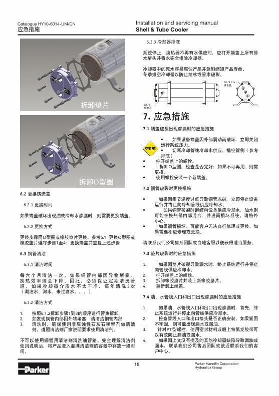
6.3.3 冷却器排液
系统停止,换热器不再有水供应时,应打开端盖上所有排水堵头并将水完全排除冷却器。
冷却器中的死水容易腐蚀产品并急剧缩短产品寿命。冬季排空冷却器以防止结冰或管束破裂。
7. 应急措施7.1 端盖破裂出现渗漏时的应急措施
• 如果设备端盖因外部震动而破坏,立即关闭运行系统压力。• 切断冷却管线冷却水供应。排空管侧(参考排液)
• 拧开端盖上的螺栓。• 拆卸O型圈,检查是否完好;如果不可再用,则需
更换。• 使用螺栓安装一个新端盖。
7.2 铜管破裂时更换措施
• 如果因季节温度过低导致铜管冻破,立即停止设备运行并终止向冷却管线供应冷却水。
• 如果铜管破裂时继续向设备供应冷却水,油水则可能在换热器内部混合,并进而损坏系统。请格外 小心。
• 如果铜管损坏,可能客户无法自行修理或更换。如果需要相应修理或更换。
请联系我们公司售后团队或当地客服以便获得适当服务。
7.3 垫片破裂时的应急措施
1. 如果因垫片破裂导致漏水时,终止系统运行并停止向管线供应冷却水。
2. 拧开端盖上的螺丝。3. 拆卸橡胶垫片并装上新橡胶垫片。4. 重新装上端盖。
7.4 油、水管线入口和出口出现渗漏时的应急措施
1. 如果油、水管线入口和出口出现渗漏时,首先,终止系统运行并停止向管线供应冷却水。
2. 检查管线入口和出口接头是否正确安装。如果紧固不牢固,则可能出现漏水或漏油。
3. 针对PT型螺栓,使用密封材料或缠上特氟龙胶带可以有效防止漏油或漏水。
4. 如果因上文没有提及的其他冷却器缺陷导致漏油或漏水,联系我们公司售后团队或就近联系我们的客户中心。
G1/4排油孔
G1/4 (3x)排水孔
拆卸垫片
拆卸O型圈

Installation and servicing manualShell & Tube Cooler
19 Parker Hannifin CorporationHydraulics Group
Catalogue HY10-6014-UM/CN保质期内维修和区域客服网络/ 附件
8. 保质期内维修和区域客服网络8.1 保质期
• 该产品严格遵守苏州派克奥莱尔(奥优泰克)质量管理和检验规程。
• 产品保质期规定为自购买产品后一年,前提是必须依照本手册说明要求进行设备操作。
8.2 服务网络
苏州派克奥莱尔(奥优泰克)地址:中华人民共和国江苏省苏州唯亭唯新路95号 二号厂房电话:+86 512 6289 1000 | 传真: +86 6289 0805网址: www.parker.com
附件
水质特征
项目 标准值趋势
腐蚀 结垢
标准
项目
Ph [25°C] 6.5 - 8.2 X X
导电性 (μS/cm)(25°C) < 800 X X
氯离子 (mgcL-/L) < 200 X
硫酸根离子 (mgSO42-/L) < 200 X
钙硬度 (mgCaCO3/L) < 150 X
酸消耗量(mgCaCO3/L) < 100 X
总硬度 (mgCaCO3/L) < 200 X
参考
项目
Fe (mgFe/L) < 1.0 X X
Cu (mgCu/L) < 0.3 X
硫离子 (mgS2-/L) 无 X
铵离子 (mgNH4+/L) < 1.0 X
硅化物离子 (mgSiO2/L) < 50 X
自由碳化合物 < 4.0 X
稳定系数 6.0 - 7.0 X X
型号
扭矩 (N.m)
适配接头排液 护盖
油 水
OST-S6-4-400 60 60 25 5
OST-S6-4-530 160 60 25 5
OST-S6-5-680 160 100 25 5
OST-S6-8-670 190 220 25 24
OST-S6-8-700 220 220 25 24

Your local authorized Parker distributor
Parker WorldwideEurope, Middle East, AfricaAE – United Arab Emirates, Dubai Tel: +971 4 8127100 [email protected]
AT – Austria, Wiener Neustadt Tel: +43 (0)2622 23501-0 [email protected]
AT – Eastern Europe, Wiener Neustadt Tel: +43 (0)2622 23501 900 [email protected]
AZ – Azerbaijan, Baku Tel: +994 50 22 33 458 [email protected]
BE/LU – Belgium, Nivelles Tel: +32 (0)67 280 900 [email protected]
BG – Bulgaria, Sofia Tel: +359 2 980 1344 [email protected]
BY – Belarus, Minsk Tel: +375 17 209 9399 [email protected]
CH – Switzerland, Etoy Tel: +41 (0)21 821 87 00 [email protected]
CZ – Czech Republic, Klecany Tel: +420 284 083 111 [email protected]
DE – Germany, Kaarst Tel: +49 (0)2131 4016 0 [email protected]
DK – Denmark, Ballerup Tel: +45 43 56 04 00 [email protected]
ES – Spain, Madrid Tel: +34 902 330 001 [email protected]
FI – Finland, Vantaa Tel: +358 (0)20 753 2500 [email protected]
FR – France, Contamine s/Arve Tel: +33 (0)4 50 25 80 25 [email protected]
GR – Greece, Athens Tel: +30 210 933 6450
HU – Hungary, Budaoers Tel: +36 23 885 470 [email protected]
IE – Ireland, Dublin Tel: +353 (0)1 466 6370 [email protected]
IT – Italy, Corsico (MI) Tel: +39 02 45 19 21 [email protected]
KZ – Kazakhstan, Almaty Tel: +7 7273 561 000 [email protected]
NL – The Netherlands, Oldenzaal Tel: +31 (0)541 585 000 [email protected]
NO – Norway, Asker Tel: +47 66 75 34 00 [email protected]
PL – Poland, Warsaw Tel: +48 (0)22 573 24 00 [email protected]
PT – Portugal, Leca da Palmeira Tel: +351 22 999 7360 [email protected]
RO – Romania, Bucharest Tel: +40 21 252 1382 [email protected]
RU – Russia, Moscow Tel: +7 495 645-2156 [email protected]
SE – Sweden, Spånga Tel: +46 (0)8 59 79 50 00 [email protected]
SK – Slovakia, Banská Bystrica Tel: +421 484 162 252 [email protected]
SL – Slovenia, Novo Mesto Tel: +386 7 337 6650 [email protected]
TR – Turkey, Istanbul Tel: +90 216 4997081 [email protected]
UA – Ukraine, Kiev Tel +380 44 494 2731 [email protected]
UK – United Kingdom, Warwick Tel: +44 (0)1926 317 878 [email protected]
ZA – South Africa, Kempton Park Tel: +27 (0)11 961 0700 [email protected]
North AmericaCA – Canada, Milton, Ontario Tel: +1 905 693 3000
US – USA, Cleveland (industrial) Tel: +1 216 896 3000
US – USA, Elk Grove Village (mobile) Tel: +1 847 258 6200 Asia PacificAU – Australia, Castle Hill Tel: +61 (0)2-9634 7777
CN – China, Shanghai Tel: +86 21 2899 5000
HK – Hong Kong Tel: +852 2428 8008
IN – India, Mumbai Tel: +91 22 6513 7081-85
JP – Japan, Fujisawa Tel: +81 (0)4 6635 3050
KR – South Korea, Seoul Tel: +82 2 559 0400
MY – Malaysia, Shah Alam Tel: +60 3 7849 0800
NZ – New Zealand, Mt Wellington Tel: +64 9 574 1744
SG – Singapore Tel: +65 6887 6300
TH – Thailand, Bangkok Tel: +662 717 8140
TW – Taiwan, New Taipei City Tel: +886 2 2298 8987 South AmericaAR – Argentina, Buenos Aires Tel: +54 3327 44 4129
BR – Brazil, Cachoeirinha RS Tel: +55 51 3470 9144
CL – Chile, Santiago Tel: +56 2 623 1216
MX – Mexico, Apodaca Tel: +52 81 8156 6000
www.parker.com
Catalogue HY10-6014-UM/CN, 04/2013, POD© 2013 Parker Hannifin Corporation. All rights reserved.