Sheath Removal and Mid-Span Access of Dielectric ALTOS...
12
p/n 004-138, Issue 1 STANDARD RECOMMENDED PROCEDURE 004-138 | ISSUE 1 | MARCH 2012 | PAGE 1 OF 12 | PRETERMINATED SYSTEMS | CABLES | CONNECTORS | CABLE ASSEMBLIES | HARDWARE | TOOL KITS AND ACCESSORIES | TEST EQUIPMENT | SPLICE EQUIPMENT | FAN-OUT KITS | TRAINING Sheath Removal and Mid-Span Access of Dielectric ALTOS ® Cable with FastAccess™ Technology Table of Contents 1. General................................................................................................................1 2. Precautions..........................................................................................................1 3. Tools and Materials..............................................................................................3 4. Cable-end Sheath Removal and Fiber Access....................................................3 5. Mid-span Sheath Removal and Fiber Access......................................................7 1. GENERAL 1.1 This procedure describes cable-end and mid-span sheath removal and fiber access of ALTOS cables which feature Corning Cable Systems FastAccess™ Technology (Figure 1). 1.2 If this procedure is reissued, a summary of changes will appear in this paragraph. 2. PRECAUTIONS Chemical Precautions WARNING: Fiber-Clean Wipes contain hydrocarbons. Apply in rooms having normal room ventilation. For prolonged and/or repeated use, gloves are recommended. Avoid eye contact. Keep away from open flames and ignition sources. If ingested, do not induce vomiting. Consult a physician. In case of eye contact, flush eyes with water for 15 minutes. Personal Protection Equipment (PPE) Precautions CAUTION: Corning Cable Systems recommends the use of safety glasses (spectacles) conforming to ANSI Z87, for eye protection from accidental injury when handling chemicals, cables, or working with fiber. Pieces of glass fiber are very sharp and have the potential to damage the eye. Water blocking tape Buffer tubes Binders Fibers Sheath Locator ridge Locator ridge Figure 1 Central member HPA-0486
Transcript of Sheath Removal and Mid-Span Access of Dielectric ALTOS...

p/n 004-138, Issue 1
STANDARD RECOMMENDED PROCEDURE 004-138 | ISSUE 1 | MARCH 2012 | PAGE 1 OF 12
| PR
ETE
RM
INAT
ED
SY
STE
MS
| C
AB
LES
| C
ON
NE
CTO
RS
| C
AB
LE A
SS
EM
BLI
ES
| H
AR
DW
AR
E |
TOO
L K
ITS
AN
D A
CC
ES
SO
RIE
S |
TES
T E
QU
IPM
EN
T | S
PLI
CE
EQ
UIP
ME
NT
| FA
N-O
UT
KIT
S |
TRA
ININ
GSheath Removal and Mid-Span Access of Dielectric ALTOS® Cable with FastAccess™ Technology
Table of Contents
1. General................................................................................................................12. Precautions..........................................................................................................13. Tools and Materials..............................................................................................34. Cable-end Sheath Removal and Fiber Access....................................................35. Mid-span Sheath Removal and Fiber Access......................................................7
1. GENERAL
1.1 This procedure describes cable-end and mid-span sheath removal and fiber access of ALTOS cables which feature Corning Cable Systems FastAccess™ Technology (Figure 1).
1.2 If this procedure is reissued, a summary of changes will appear in this paragraph.
2. PRECAUTIONSChemical Precautions
WARNING: Fiber-Clean Wipes contain hydrocarbons. Apply in rooms having normal room ventilation. For prolonged and/or repeated use, gloves are recommended. Avoid eye contact. Keep away from open flames and ignition sources. If ingested, do not induce vomiting. Consult a physician. In case of eye contact, flush eyes with water for 15 minutes.
Personal Protection Equipment (PPE) Precautions
CAUTION: Corning Cable Systems recommends the use of safety glasses (spectacles) conforming to ANSI Z87, for eye protection from accidental injury when handling chemicals, cables, or working with fiber. Pieces of glass fiber are very sharp and have the potential to damage the eye.
Water blocking tape
Buffer tubes
Binders
Fibers
Sheath
Locator ridge
Locator ridge
Figure 1
Centralmember
HPA-0486

STANDARD RECOMMENDED PROCEDURE 004-138 | ISSUE 1 | MARCH 2012 | PAGE 2 OF 12
PRECAUTIONS -continued
CAUTION: The wearing of cut-resistant safety gloves to protect your hands from accidental injury when using sharp-bladed tools is strongly recommended. To minimize the chance of injury from sharp-bladed tools, always cut away from yourself and others. Dispose of used blades and armor scrap properly.
Laser Precautions
Cable and Fiber Handling Precautions
CAUTION: Fiber optic cable is sensitive to excessive pulling, bending, and crushing forces. Consult the cable specification sheet for the cable you are installing. Do not bend the cable more sharply than the minimum recommended bend radius. Do not apply more pulling force to the cable than specified. Do not crush the cable or allow it to kink. Doing so may cause damage that can alter the transmission characteristics of the cable; the cable may have to be replaced.
CAUTION: The typical filler rod color in the cable described in this procedure is black. Careful attention should be taken to avoid accidental cutting of live buffer tubes; particularly white and black tubes. In mid-span applications, Corning Cable Systems recommends coiling all tubes and filler rods in the slack storage area of the splice closure; especially for cables with fiber counts above 96 fibers. Avoid cutting any filler rods unless necessary for storage space considerations. When in doubt regarding the buffer tube color code and filler rod placement, contact Corning Cable Systems Engineering Services for assistance prior to cutting.
WARNING: Care must be taken while handling fibers during mid-span access procedures to avoid causing large deviations in optical power throughput on fibers carrying communications traffic.INTERRUPTION OF SYSTEM TRAFFIC MAY RESULT FROM NEGLIGENT HANDLING OF FIBERS.
CAUTION: Cleaved or broken glass fibers are very sharp and can pierce the skin easily. Do not let these pieces of fiber stick to your clothing or drop in the work area where they can cause injury later. Use tweezers to pick up cleaved or broken pieces of glass fibers and place them on a loop of tape kept for that purpose alone. Good housekeeping is very important.
CAUTION: Never look directly into the end of a fiber that may be carrying laser light. Laser light can be invisible and can damage your eyes. Viewing it directly does not cause pain. The iris of the eye will not close involuntarily as when viewing a bright light. Consequently, serious damage to the retina of the eye is possible. Should accidental eye exposure to laser light be suspected, arrange for an eye examination immediately.
STANDARD RECOMMENDED PROCEDURE 004-138 | ISSUE 1 | MARCH 2012 | PAGE 3 OF 12
3. TOOLS AND MATERIALS
3.1 The following tools and materials are required to complete this procedure:
• Tape measure (Corning p/n 100305-01) • Permanent marker • Vinyl tape (100278-01 • Utility knife with hook blade (100299-01) • Diagonal cutting pliers (side cutters) (100300-01) or Scissors (100294-01) • Seam ripper (100304-01 ) • Coaxial Cable stripper (100107-01) and its instructions, SRP-005-007, Scoring Fiber Optic Tubes with a Coaxial Cable Stripper (100107-01, 3204002-01) • Small slotted screwdriver (100332-01) • Needle nose pliers
and for Mid-span applications:
• Optical Fiber Access Tool (OFAT) (OFT-000) and its instructions, SRP-004-014, Corning Cable Systems Optical Fiber Access Tool (OFT-000). • Splice closure and any tools / materials necessary for its installation. • Splice tray(s) and any tools / materials necessary for its installation.
4. CABLE-END SHEATH REMOVAL AND FIBER ACCESS
4.1 Refer to the documentation for the hardware in which you are installing the cable for the required sheath removal strip length.
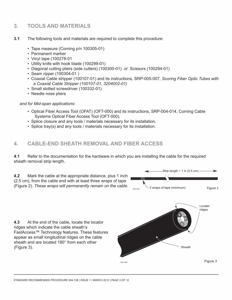
4.2 Mark the cable at the appropriate distance, plus 1 inch (2.5 cm), from the cable end with at least three wraps of tape (Figure 2). These wraps will permanently remain on the cable.
4.3 At the end of the cable, locate the locator ridges which indicate the cable sheath’s FastAccess™ Technology features. These features appear as small longitudinal ridges on the cable sheath and are located 180° from each other (Figure 3).
Strip length + 1 in (2.5 cm)
3 wraps of tape (minimum)HPA-0487 Figure 2
Sheath
Locaterridges
Figure 3HPA-0488

STANDARD RECOMMENDED PROCEDURE 004-138 | ISSUE 1 | MARCH 2012 | PAGE 4 OF 12
Cable-end Sheath Removal
Note: Use one of the following two methods to access the cable core with FastAccess™ Technology:
Using FastAccess™ Technology - Method A - Cutting the Outer Sheath
4.4 For small fiber-count cables, use side cutters or scissors to make a 1-inch (2.5cm) longitudinal cut through the cable end along the FastAccess™ Technology locator ridges (Figure 4).
For large fiber-count cables, use side cutters to make 1-inch (2.5cm) longitudinal cuts through the cable end along each FastAccess™ Technology locator ridge (Figure 5).
NOTE: The resulting cuts in the outer sheath need to be long enough to allow you to grip each side of the split sheath with a gloved hand. If the cut is too short for you to do so, use needle nose pliers to begin the split along the locator ridges.
4.5 Grip each side of the split sheath and pull the sides 90° from the cable core. Continue to pull the sheath until it is split to the tape wraps (Figure 6).
Skip to Step 4.7 on page 5
Figure 41 in (2.5 cm)HPA-0489
Figure 51 in (2.5 cm)
1 in (2.5 cm)
HPA-0513
Figure 6HPA-0490
Tape wraps
Cable core
STANDARD RECOMMENDED PROCEDURE 004-138 | ISSUE 1 | MARCH 2012 | PAGE 5 OF 12
Using FastAccess™ Technology - Method B - Needle Nose Pliers
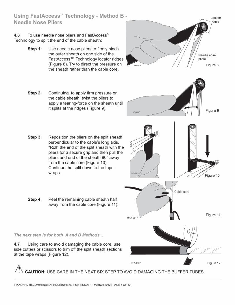
4.6 To use needle nose pliers and FastAccess™ Technology to split the end of the cable sheath:
Step 1: Use needle nose pliers to firmly pinch the outer sheath on one side of the FastAccess™ Technology locator ridges (Figure 8). Try to direct the pressure on the sheath rather than the cable core.
Step 2: Continuing to apply firm pressure on the cable sheath, twist the pliers to apply a tearing-force on the sheath until it splits at the ridges (Figure 9).
Step 3: Reposition the pliers on the split sheath perpendicular to the cable’s long axis. “Roll” the end of the split sheath with the pliers for a secure grip and then pull the pliers and end of the sheath 90° away from the cable core (Figure 10). Continue the split down to the tape wraps.
Step 4: Peel the remaining cable sheath half away from the cable core (Figure 11).
The next step is for both A and B Methods...
4.7 Using care to avoid damaging the cable core, use side cutters or scissors to trim off the split sheath sections at the tape wraps (Figure 12).
CAUTION: USE CARE IN THE NEXT SIX STEP TO AVOID DAMAGING THE BUFFER TUBES.
Locatorridges
Figure 8HPA-0514
Needle nosepliers
Figure 9HPA-0515
Figure 10HPA-0518
Figure 11HPA-0517
Cable core
HPA-0491 Figure 12
STANDARD RECOMMENDED PROCEDURE 004-138 | ISSUE 1 | MARCH 2012 | PAGE 6 OF 12
Cable-end Sheath Removal-
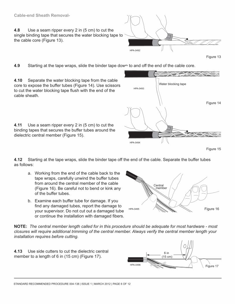
4.8 Use a seam ripper every 2 in (5 cm) to cut the single binding tape that secures the water blocking tape to the cable core (Figure 13).
4.9 Starting at the tape wraps, slide the binder tape down to and off the end of the cable core.
4.10 Separate the water blocking tape from the cable core to expose the buffer tubes (Figure 14). Use scissors to cut the water blocking tape flush with the end of the cable sheath.
4.11 Use a seam ripper every 2 in (5 cm) to cut the binding tapes that secures the buffer tubes around the dielectric central member (Figure 15).
4.12 Starting at the tape wraps, slide the binder tape off the end of the cable. Separate the buffer tubes as follows:
a. Working from the end of the cable back to the tape wraps, carefully unwind the buffer tubes from around the central member of the cable (Figure 16). Be careful not to bend or kink any of the buffer tubes.
b. Examine each buffer tube for damage. If you find any damaged tubes, report the damage to your supervisor. Do not cut out a damaged tube or continue the installation with damaged fibers.
NOTE: The central member length called for in this procedure should be adequate for most hardware - most closures will require additional trimming of the central member. Always verify the central member length your installation requires before cutting.
4.13 Use side cutters to cut the dielectric central member to a length of 6 in (15 cm) (Figure 17).
HPA-0492
Figure 13
HPA-0493
Figure 14
Water blocking tape
HPA-0494
Figure 15
Central member
HPA-0495 Figure 16
(15 cm) 6 in
HPA-0496 Figure 17

STANDARD RECOMMENDED PROCEDURE 004-138 | ISSUE 1 | MARCH 2012 | PAGE 7 OF 12
Cable-end Fiber Access
NOTES: Only access the fibers when you are ready to terminate or splice them.
Before using the coaxial cable stripper, follow the adjustment and test procedures in SRP-005-007, Scoring Fiber Optic Tubes with a Coaxial Cable Stripper. to make sure that the stripper is properly adjusted and that it has a sharp blade.
4.14 Consult the instructions of the hardware in which the fibers will be installed for the required buffer tube length. Measure and mark this length on the buffer tubes with a permanent marker.
4.15 To score the first tube:
a. Position the stripper’s blade on the scoring mark.
b. Hold the tube steady with one hand to prevent it from twisting.
c. Use your other hand to rotate the tool around the tube two to three complete turns to score it (Figure 18).
d. Remove the tool from the tube.
4.16 Carefully flex the tube to break it at the score point (Figure 19).
4.17 Slide the scored section of tube off of the fibers (Figure 20).
4.18 Use scissors to trim 1 inch (2.5 cm) from the end of the fibers. The fibers are now ready to be cleaned and terminated (Figure 21).
4.18 Repeat steps 4.15 - 4.18 on the remaining buffer tubes/fibers.
HPA-0497
Figure 10
Score the tube- do not ring cut it
Figure 19
HPA-0498
HPA-0499Figure 20
Figure 21
1 in (2.5 cm)
HPA-0500

STANDARD RECOMMENDED PROCEDURE 004-138 | ISSUE 1 | MARCH 2012 | PAGE 8 OF 12
5. MID-SPAN SHEATH REMOVAL AND FIBER ACCESS
5.1 This procedure is dependent upon sufficient slack cable for access and uses the OFT-000 Optical Fiber Access Tool. The minimum amount of cable slack is determined as follows:
Slack needed= 60 x cable diameter + 42 in (105 cm): for example, for a 0.5 in (1.25 cm) OD cable, 60 X 1.25 =75cm plus 105 cm = 72 in (180 cm) of slack
Add any necessary additional slack needed to reach the splicing workstation from a pole or manhole.
5.2 Prepare the tie-in (drop) cable according to the appropriate cable stripping procedure. If the tie-in cable is armored and grounding is required, install a grounding clip or connector at this time. Set the tie-in cable aside in a secure place.
5.3 Determine the center of the slack loop of the cable being accessed and mark it with a permanent marker.
5.4 Measure half of the total length to be accessed in each cable direction from the loop mid-point.
Wrap each of these points with at least 3 wraps of vinyl tape. The total length from tape wrap to tape wrap should equal the full desired strip length (Figure 22).These wraps will permanently remain on the cable.
WARNING: Care must be taken while handling fibers during mid-span access procedures to avoid causing large deviations in optical power throughput on fibers carrying communications traffic.INTERRUPTION OF SYSTEM TRAFFIC MAY RESULT FROM NEGLIGENT HANDLING OF FIBERS.
Mid-span Sheath Removal
5.5 At one tape wrap, on the inside of the slack loop, use a hook-blade knife to make a ring cut through the outer sheath (Figure 23). USE CARE TO AVOID CUTTING THE CABLE CORE AND BUFFER TUBES BENEATH THE SHEATH.
5.5 At the ring cut, find the locator ridges which indicate the cable sheath’s FastAccess™ Technology features. These features appear as small longitudinal ridges on the cable sheath and are located 180° from each other. See Figure 1 for a cross-section view of the cable.
(center) markHalf-distance
3-layer minimum
HPA-0501
Figure 22
tape wraps
HPA-0502 Figure 23
Ring cut

STANDARD RECOMMENDED PROCEDURE 004-138 | ISSUE 1 | MARCH 2012 | PAGE 9 OF 12
Mid-span Sheath Removal-continued
5.6 To mid-span access the cable core:
Step 1: Use needle nose pliers to firmly pinch the outer sheath on one side of the FastAccess™ Technology locator ridges (Figure 24). Direct the pressure on the sheath rather than the cable core.
Step 2: Continuing to apply firm pressure on the cable sheath, twist the pliers to apply a tearing-force on the sheath until it splits at the ridges (Figure 25).
Step 3: Reposition the pliers on the split sheath perpendicular to the cable’s long axis. “Roll” the end of the split sheath with the pliers for a secure grip and then pull the pliers and end of the sheath 90° away from the cable core (Figure 26).
Continue the split down to the opposite tape wraps.
5.7 Grip the remaining side of the split sheath and pull it 90° from the cable core until it is also separated to the opposite tape wraps (Figure 27).
Locator ridge
Locator ridge
Figure 24 HPA-0504
Needle nosepliers
Tape wraps
Ring cut
Figure 25HPA-0515
HPA-0503 Figure 26
Figure 27HPA-0505
Cable core
STANDARD RECOMMENDED PROCEDURE 004-138 | ISSUE 1 | MARCH 2012 | PAGE 10 OF 12
Mid-span Sheath Removal-continued
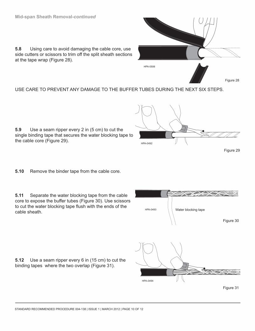
5.8 Using care to avoid damaging the cable core, use side cutters or scissors to trim off the split sheath sections at the tape wrap (Figure 28).
USE CARE TO PREVENT ANY DAMAGE TO THE BUFFER TUBES DURING THE NEXT SIX STEPS.
5.9 Use a seam ripper every 2 in (5 cm) to cut the single binding tape that secures the water blocking tape to the cable core (Figure 29).
5.10 Remove the binder tape from the cable core.
5.11 Separate the water blocking tape from the cable core to expose the buffer tubes (Figure 30). Use scissors to cut the water blocking tape flush with the ends of the cable sheath.
5.12 Use a seam ripper every 6 in (15 cm) to cut the binding tapes where the two overlap (Figure 31).
HPA-0506
Figure 28
HPA-0492
Figure 29
HPA-0493
Figure 30
Water blocking tape
HPA-0494
Figure 31
STANDARD RECOMMENDED PROCEDURE 004-138 | ISSUE 1 | MARCH 2012 | PAGE 11 OF 12
Mid-span Sheath Removal-continued
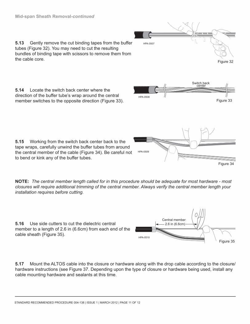
5.13 Gently remove the cut binding tapes from the buffer tubes (Figure 32). You may need to cut the resulting bundles of binding tape with scissors to remove them from the cable core.
5.14 Locate the switch back center where the direction of the buffer tube’s wrap around the central member switches to the opposite direction (Figure 33).
5.15 Working from the switch back center back to the tape wraps, carefully unwind the buffer tubes from around the central member of the cable (Figure 34). Be careful not to bend or kink any of the buffer tubes.
NOTE: The central member length called for in this procedure should be adequate for most hardware - most closures will require additional trimming of the central member. Always verify the central member length your installation requires before cutting.
5.16 Use side cutters to cut the dielectric central member to a length of 2.6 in (6.6cm) from each end of the cable sheath (Figure 35).
5.17 Mount the ALTOS cable into the closure or hardware along with the drop cable according to the closure/hardware instructions (see Figure 37. Depending upon the type of closure or hardware being used, install any cable mounting hardware and sealants at this time.
HPA-0507
Figure 32
HPA-0508Figure 33
Switch back center
HPA-0509
Figure 34
2.6 in (6.6cm)
Figure 35HPA-0510
Central member
STANDARD RECOMMENDED PROCEDURE 004-138 | ISSUE 1 | MARCH 2012 | PAGE 12 OF 12
Corning Cable Systems LLC • PO Box 489 • Hickory, NC 28603-0489 USA 1-800-743-2671 • FAX +1-828-325-5060 • International +1-828-901-5000 • http://www.corning.com/cablesystems
Corning Cable Systems reserves the right to improve, enhance, and modify the features and specifications of Corning Cable Systems’ products without prior notification. ALTOS is a registered trademark of Corning Incorporated. All trademarks are the properties of their respective owners. Corning Cable Systems is ISO 9001 certified.
© 2012 Corning Cable Systems. All rights reserved. Published in the USA.
Mid-span Fiber Access
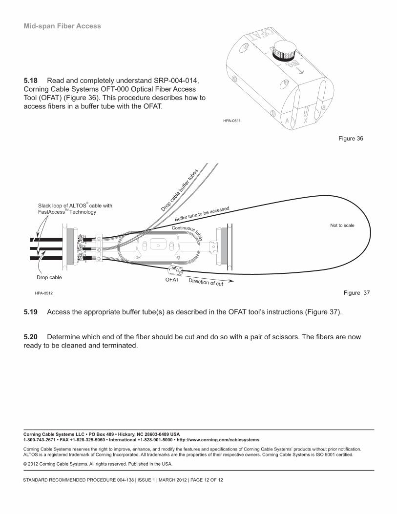
5.18 Read and completely understand SRP-004-014, Corning Cable Systems OFT-000 Optical Fiber Access Tool (OFAT) (Figure 36). This procedure describes how to access fibers in a buffer tube with the OFAT.
5.19 Access the appropriate buffer tube(s) as described in the OFAT tool’s instructions (Figure 37).
5.20 Determine which end of the fiber should be cut and do so with a pair of scissors. The fibers are now ready to be cleaned and terminated.
HPA-0511
Figure 36
Continuous tubes
Buffer tube to be accessed
Not to scale
OFAT
Slack loop of ALTOS cable withFastAccess Technology
Direction of cut
Drop
cable
buffe
r tub
es
Figure 37HPA-0512
TM
®
Drop cable