Sheath Fault Locator Logactive number at each fault site and compare it to the reference number. The...
45
9890XT SFL2 Dx Sheath Fault Locator Log Operation Manual
Transcript of Sheath Fault Locator Logactive number at each fault site and compare it to the reference number. The...

9890XT SFL2 DxSheath Fault Locator
Log
Operation Manual

2
ISO 9001 CERTIFIED
Metrotech has received ISO 9001 Quality Management System Certification.
Metrotech adheres to the quality standard guidelines of ISO 9001 and ensures quality in its design/development, production, installation, and servicing disciplines.
© Metrotech Corporation 2005
Metrotech Corporation488 Tasman DriveSunnyvale, CA 94089USA
Tel: 1.800.446.3392; 1.408.734.1400Fax: 1.408.734.1415E-mail: [email protected]: www.metrotech.com
Revision B March 2005

TABLE OF CONTENTS
List of Illustrations ...1
1 Introduction . .. . . 2
2 Safety Precautions ...3
3 9890XT SFL-2 Quick Start Guide for the Experienced User 4
4 9890XT SFL-2 Equipment ...104.1 Standard Equipment . .104.2 Optional Accessories .124.3 Technical Specifications ...134.4 Transmitter Controls and Indicators . 164.5 Transmitter Features .184.6 A-Frame Receiver Controls and Indicators ..204.7 Additional A-Frame Receiver Features 21
5 Principles of Operation .225.1 Functional Theory ...225.1.1 Earth Voltage Gradient.. 245.1.2 Equipotentials .. ..245.1.3 Multiple Fault Patterns .. 265.1.4 Distortion Due to Adjacent Conductors 26
6 Checkout Procedure . . . . . . . . . . . . . . . . . . . . . . . . . . . . . . . . . . . . . . . 27
7 Operation . .. . ....29 7.1 Check the Batteries Prior to Going into the Field . 29 7.2 Ensure all conductors are de-energized. .. .29
7.3 Lift the Grounds 29 7.4 Attach the Transmitter to the Conductor-Check Fault Resistance ...29 7.5 Synchronize the A-Frame Receiver .30
7.6 Confirm that a Fault Exists . ..327.7 Trace the Cable with the 9890XT Receiver . ... ..327.8 Pinpoint the Fault . .327.9 Verify the Fault . 32

8 Advanced Techniques ... . .. .... .. .. ....338.1 Faults Under Inaccessible Surfaces . ..338.1.1 Perpendicular Method ..338.1.2 Triangulation Method ... .348.2 Faults Under Pavement .. ..358.3 Long Distance Tracing 358.4 High and Low Impedance Faults .. .368.5 Multiple Faults . ..36
9 Maintenance . . . . . . . . . . . . . . . . . . . . .. . . . . . . . . . . . . . . . . . . . . . . 379.1 Receiver Battery Replacement . .379.2 Service Center . ..38
Appendix . 39
Copyright . 40
Warranty . 41

1
LIST OF ILLUSTRATIONS
Figure 3-1: Fault Resistance Scale .4Figure 3-2: Clamping Black Lead to Ground Rod .. .. ...5Figure 3-3: Clamping Red Lead to Targeted Cable. . ...5Figure 3-4: Locating the Targeted Cable .. . . 5Figure 3-5: Positioning of A-Frame Receiver for Synchronization .6Figure 3-6: Locating the Cable Fault with A-Frame Receiver . . .7Figure 4-1: Standard Equipment . 11Figure 4-2: Transmitter Controls Panel . .. .16Figure 4-3: A-Frame Controls and Indicators . 20Figure 4-4: Battery Status Indication .21Figure 5-1: Typical SFL-2 Transmitter Connection 23Figure 5-2: Signal Pattern Around Fault and Ground Point .. 24Figure 5-3: Multiple Fault Signal Patterns .. 26Figure 6-1: Checkout Test Set-Up . 27Figure 7-1: Synchronizing the A-frame .30Figure 7-2: Fault Confirmation . 31Figure 8-1: Perpendicular Method 33Figure 8-2: Triangulation Method 34Figure 8-3: Locating an Equipotential Circle .. 34Figure 8-4: Fault Location Using Extension Cable for
Increased Sensitivity .. 35Figure 9-1: Receiver Battery Replacement .. 37

2
1 INTRODUCTION
The Metrotech 9890XTSFL Sheath Fault Locator system is designed to detect andpinpoint sheath and other conductor faults that are in direct contact with the earth.
The 9890XTSFL offers these unique features:
Fault level measurement at the Transmitter
Simultaneous fault finding and line tracing.
Signal strength and reference LCD s on the A-Frame for judgingproximity to faults, comparing multiple faults, and detectingpinholes and trees in power cable.Detection of low and high resistance faults.
Automatic battery checking and low battery warning
Non-polarized A-Frame.
Single-handed operation. No need to carry locator receiver as well
as A-frame.
Operation of the unit is completely automatic; there are no operator adjustments required.Both the Transmitter and Receiver are water resistant and built to withstand the rigors offield use.

3
2 SAFETY PRECAUTIONS
1 Metrotech Utility Line and Sheath Fault Locators are intended for use by utility and contractor professionals. Safety hazards for underground utility access areas include electrical shock, explosive gases, and toxic fumes as well as potential influence on communications and control systems such as traffic control and railroad crossings.
2 Familiarize yourself with all required safety practices of the local utility company, or other owner of the plant before entering an access area or connecting a Metrotech transmitter.
3 Before connecting transmitter directly to any conductor, make sure that the line is de-energized and out of service. Never make a direct connection to a live power cable.
4 Before connecting the transmitter directly to any conductor, make sure the operating ground (black cable) is connected to the ground rod.
5 If you use the Metroclamp on energized electrical or control lines follow appropriate safety procedures to avoid the risk of injury.
6 Pay special attention when using a locator in high traffic areas.

4
3 9890XT SFL SHEATH FAULT LOCATOR QUICK START FOR THE EXPERIENCED USER
1 Check Batteries Prior to Departing for the FieldCheck the batteries in the Transmitter, Receiver, and A-Frame.Replace/recharge if necessary. Turn the instruments off.
2 Ensure all conductors are de-energized
3 Lift GroundsLift Grounds (of all conductors in the circuit) at both ends of the faulted cable section.
WARNINGWhen the Transmitter is set to SFL , the external OUTPUT JACKS produceHigh Voltage. Do not touch these jacks, electrical shock will result!
4 Attach Transmitter to Conductor Check Fault Resistance
1 Turn Transmitter OFF.
2 Plug Black and Red leads into the Transmitter.
3 Stretch Black-lead 180 degrees away from conductor.
4 Push grounding rod into earth and clamp black lead to grounding rod. Establish the best ground possible. See figure 3-2
5 Clamp Red lead to target conductor sheath. See Figure 3-3
6 Turn Transmitter power knob to SFL position.
Check fault resistance scale: See Figure 3-1
0-100k ohms Severe Fault
100k 500k ohms Medium Fault
1 Megohm and above Light Faults
Note: Read the number below the oscillating bar to check the quality of the targeted cable. The fault resistance on
Figure 3-1 is 10K ohms (Severe Fault).Figure 3-1: Fault Resistance Scale

5
Figure 3-2: Clamping Black Lead to Ground Rod
Figure 3-3: Clamping Red Lead to Conductor
5 Use the 9890XT Line Locator Receiver to Trace the Cable
Trace and mark the cable as you proceed towards the fault.
Figure 3-4: Locating the Targeted Cable

6
6 Synchronize the A-Frame Receiver and establish reference value of fault
(A-Frame receiver has a one-color band above each spike (Black or White)
1 Hold the A-Frame Receiver so the spike with the black band is about 2 steps
away from the ground rod and the spike with the white band is in-line with the
targeted cable. The A-frame receiver must be placed as shown in figure 3-5
for synchronization and for unit to operate correctly. Push the A-Frame spikes
into the ground. Switch the Receiver ON wait until arrow flashes.
Figure 3-5: Positioning of A-Frame Receiver for Synchronization
2 Monitor bar-graph LCD display for arrow direction. If the arrow points
away from the ground rod, there is a fault.
3 If the arrow points towards the ground rod, there is no fault, and
grounds and connections need to be rechecked
4 A reference number will be displayed at turn on and will stay fixed until
A-frame is turned off. The reference number indicates
the potential gradient associated with the fault at the synchronization
location.
5 The active number will be displayed at the same time as the reference
number, but it will change when the A-frame spikes are pulled out. The
active number will decrease when you move away from the
synchronization location and will increase as you get closer to the fault on
the cable. The active and reference numbers are available to help you
differentiate major faults from minor faults. See Figure 3-6.

7
Figure 3-6 : Locating the Cable Fault with A-Frame Receiver

8
7 Pinpoint the Fault
1 Keep the A-Frame parallel to the target cable.
2 Insert the A-Frame every 10-20 ft. Follow the arrow.
3 When the arrow changes direction, backtrack. Look at the active numberand compare it to the reference number. If the active number is similar tothe reference number, you have located the main fault.
4 Insert the A-Frame every two feet until the arrow changes direction again.
5 Move the A-Frame across the cable until a slight movement causes thearrow to change direction. The fault is located at the center of theA-Frame.
6 Check entire cable for multiple faults. If more faults are present, check theactive number at each fault site and compare it to the reference number.The higher the active number the larger the fault.
If you have difficulty with your Metrotech SFL-2 Sheath Fault Locator, check the manual for additional tips. If it still doesn t work, call us at 1-800-446-3392.

9
NOTE: This equipment has been tested and found to comply within limits for a Class Bdigital device, pursuant to Part 15 of the FCC Rules. These limits are designed to provide reasonable protection against harmful interference in residential installations. Thisequipment generates, uses, and can radiate radio frequency energy. If not installed andused in accordance with the instructions, it may cause harmful interference to radiocommunications. However, there is no guarantee that interference will not occur in aparticular installation. If this equipment does cause interference to radio or televisionreception (Which can be determined by turning to the locating equipment off and on). We suggest the user try to eliminate the interference by one or more of the followingmeasures:
Reorient or relocate the receiving antenna.Move the equipment away from the Receiver.Plug the equipment into an outlet on a circuit different fromthat to which the Receiver powered. If necessary, the usershould consult the dealer or an experienced radio/televisiontechnician for additional suggestions.
CAUTION: Only equipment certified to comply with Class B (computer input/outputdevices, terminals, printers, etc.) should be attached to this equipment. Finally, anychanges or modifications to the equipment by the user not expressly approved by theguarantor or manufacturer could void the users authority to operate such equipment.

10
4 MODEL 9800XT SFL EQUIPMENT
4.1 Standard Equipment
The SFL transmitter is an option to the 9860XT and 9890XT Locator System and isdesignated by the F in the Part Number. When the SFL option is selected, the standardequipment may include:
Part Model # Description Remarks
9860XT_FXT 4.8 Hz, 9.82kHz, 82 kHz Transmitter9890XT_FXT 4.8Hz, 982 Hz, 9.8 kHz, 82 kHz Transmitter9860XT_FXT 9.82kHz, 82 kHz, 50/60 Hz, Receiver
14-22 kHz9890XT_FXT 982 Hz, 9.8 kHz, 82 kHz Receiver
50/60 Hz, 14-22 kHz
10498 4.8Hz A-Frame Receiver
400B196-1 Red Test Cable
400B196-2 Black Test Cable
600A113 Operating Manual
500B353 Foam pads

11
Figure 4-1: Standard Equipment and Accessories
Standard:1. 9800XT Receiver2. 9800XT Transmitter3. Conductive Attachments4. Ground Rod5. Carrying Case6. SFL 2 Receiver7. Operation Manual
Accessories:
8. MetroClamp9. Flex-Sonde10. High Power Sonde11. Standard Power Sonde
12
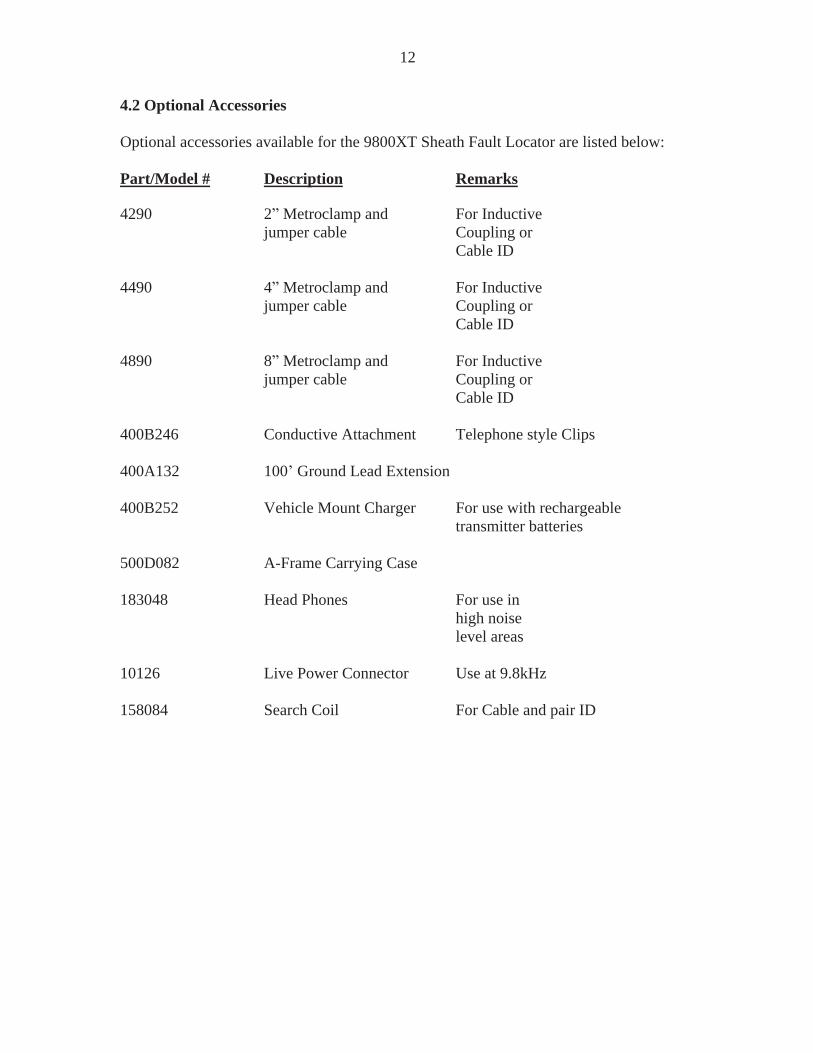
4.2 Optional Accessories
Optional accessories available for the 9800XT Sheath Fault Locator are listed below:
Part/Model # Description Remarks
4290 2 Metroclamp and For Inductive jumper cable Coupling or
Cable ID
4490 4 Metroclamp and For Inductivejumper cable Coupling or
Cable ID
4890 8 Metroclamp and For Inductivejumper cable Coupling or
Cable ID
400B246 Conductive Attachment Telephone style Clips
400A132 100 Ground Lead Extension
400B252 Vehicle Mount Charger For use with rechargeable transmitter batteries
500D082 A-Frame Carrying Case
183048 Head Phones For use in high noiselevel areas
10126 Live Power Connector Use at 9.8kHz
158084 Search Coil For Cable and pair ID

13
4.3 Technical Specifications
TRANSMITTEROutput Frequencies: Model Frequencies
9860XT* 4.8Hz, 9.82kHz, 82kHz 9890XT* 4.8Hz, 982Hz, 9.82kHz, 82kHz
Audio Output: Pulsing tone to indicate Transmitter output is active.
Line Tracing Ohmmeter: 0-2 kOhm
Fault Metering: Continuous fault resistance monitoring 0 to 10M Ohm.
Automatic Best Frequency Selection
Nominal Output Power Conductive Mode: Model Watts
9860XT 3*9890XT 3** Output power limited to.7W at 82kHz
Power Settings: Low and High (all models)
Battery Type: Ten D Cells Optional Rechargeable NiCd
Battery Life: Alkaline 28-70 hours NiCd 9-22 hours Continuous use, depending on power and Frequency selection.
Battery Check: Automatic at start up
OperationTemperature: -4º to +122º F (-20º to +50º C)
Dimensions: 14.25 L x 9.25 W x 5.25 H(36.2 cm x 23.5 cm x 13.3 cm)
Weight: 8.9 lbs. (4 kg)

14
Technical Specifications (4.3 cont d)
A-FRAME RECEIVER
Frequency: 4.8 Hz Crystal Controlled
Input Sensitivity: 5 MV
Sensitivity Control: Automatic
Dynamic Range:
Bargraph 72 dB
Numerical LCD 60 dB
Output Indication:Bargraph LCD Flashing LCD arrows point to fault. 12 segment LCD
bargraph indicates signal level, each bar = 6dB.Numerical LCD Active Displays potential gradient to pinpoint and
differentiate multiple faults.Reference Displays maximum potential gradient atsynchronization location and can be compared to activenumber for pinpointing major fault.
Battery: 9 V NEDA 1604 or equivalent.
Battery Life: 100 hours continuous use.
Battery Test. Automatic at power on
Weight: 4.4 lb (2.0 kg)
Dimensions: 32 in. H x 22 in. W x 1 in.
(81 cm x 56 cm x 2.5 cm)
Operational Temp: -4 to + 120 degrees F

15
Technical Specifications (4.3 cont d)
9800XT RECEIVER
Frequencies: Model Frequencies9860XT Active - 9.82kHz, 82kHz
Passive - 50/60Hz, 14-22kHz9890XT Active - 982Hz, 9.82kHz, 82kHz
Passive - 50/60Hz, 14-22kHz
DepthReadoutAccuracy: Passive-+(5% + 2 ) under normal conditions
Active- +(5% + 2 ) under normal conditions
Distance Sensitive Left/Right GuidanceTM
Real-Time Continuous Gain AdjustmentTM and Manual Gain Control
Simultaneous Peak and Null DisplayTM
Current Measurement
Backlighting: Standard on all 9800XT receivers
Serial link: RS232
Battery Type: Six AA Cells
Battery Life: 30 hours continuous use 24 hours continuous backlit use
Battery Check: Continuous Automatic Operation
Temperature: -4º to +122º F (-20º to +50º C)
Dimensions: 27 L x 7 W x 9 H(68.6 cm x 17.8 cm x 22.9 cm)
Weight: 5.4 lbs. (2.35 kg)

16
4.4 Transmitter: Controls and Indicators
WARNINGWhen the Transmitter is set to SFL , the external OUTPUT JACKS producehigh voltage. Do not touch these jacks, electrical shock will result!
See Figure 4-2 for location of Transmitter controls and indicators described below:
Figure 4-2: Transmitter Control Panel
1 Output Clamp Jack2 Conductor Arrow3 Charge Jack4 Frequency Knob5 LCD Display6 Power Knob7 Battery Access Caps8 SFL Conductive Attachment Output Jack

17
OUTPUT CLAMP JACKInsert the MetroClamp phone plug into this jack only.
CONDUCTOR ARROWAlign this arrow with your targeted conductor when you are locating in the Inductive mode.
CHARGE JACK (Optional Feature) If you have purchased a 9890XT with the Rechargeable NiCd Battery feature, your
Transmitter will have a jack for connecting the Wall Mount Charger or the VehicleMount Charger. The Jack is located on the right inside wall of the Transmitter
FREQUENCY (Hz) KNOBModel 9890XT can transmit up to three active frequencies.
Frequencies on 9860XT and 9890XT Transmitter:AUTO - Automatic frequency select
982Hz - Low audio (9890XT only)9.8kHz - Audio frequency82kHz - Radio frequency
ALL - All frequencies are transmitted ontoBAT CHG (Optional)Only on rechargeable units. Battery Charger jack for connecting optional battery charger to Transmitter. Complete recharging is 10-14 hours. Recharge or replace the Transmitter batteries when the battery charge indicator gets below 5 bars.
FAULT TESTThe ohm meter indicates the battery charge level and total fault resistance measured onthe conductor. The meter continuously displays this value during operation.
POWER KNOBTurn the Power Knob to the SFL position to activate fault locating. An audible pulsing tone indicates Transmitter output is active. Turn the Power Knob OFF to deactivateTransmitter. The Transmitter will automatically shut off when the battery charge is toolow.
BATTERY ACCESS CAPSRemove end caps to gain access to the batteries. Note battery polarity, which is
indicated on the bottom of the Transmitter and batteries.
SFL CONDUCTIVE ATTACHMENT OUTPUT JACKJacks for connecting red and black lead cables to the Transmitter. Maintain theconvention of connecting the black cable to the grounding spike and the black lead to theback input. Connect the red cable to the sheath under test, and the red lead to the redinput. Failure to do so will cause the A-frame to point toward the ground spike and away from the fault.

18
4.5 Transmitter: Features
LCD BARGRAPH DISPLAY - The bar graph indicates four types of information:
BATTERY STATUS - First 3 seconds the amount of Transmitter battery charge is indicated by the number of bars illuminated.
CIRCUIT RESISTANCE - The blinking bar indicates, in ohms, the amount of signal resistance on your conductor and your faulted cable.
OUTPUT LEVEL - The solid bars indicate the amount of signal strength (current output) on your conductor.
POOR CONDUCTOR AND IMPROPER SELECTION - Entire display blinks and Transmitter beeps very fast or emits a constant beeping tone.
SPEAKER (not shown) - Transmitter audio tone changes according to operating function:
Speaker Tone DescriptionEvery 5 seconds Good transmitter connectionVery fast Low battery warning and
poor conductor alertConstant Improper selection alert

19
POWER KNOB - The amount of transmitter signal output for each power setting changes according to which frequency you are using:
Power Setting Frequency982Hz 9.82kHz 82kHz
L-Low 0.3 watts 0.3 watts 0.15 wattsM-Medium 1 watt 1 watt 0.25 wattsH-High 3 watts 3 watts 3 wattsSheath Fault Locating* 0.5 watts 0.35 watts
*Sheath Fault Locating - Set at this option for simultaneous sheath fault locating capability. The SFL-2 A-Frame will receive the 4.8Hz sheath fault locating frequency; the 9800XT Receiver will receive the selected active frequency.

20
4.6 A-Frame Receiver Controls and Indicators See Figure 4-3 for location of Receiver controls described below:
On/Off Button Push and release to turn ON . Push and release to turn OFF .
LCD Displays:
BargraphThe flashing arrows of the bar graph will display the direction to the fault and the number of bars displayed reflect the magnitude of the fault.
ActiveThe Active LCD will display in numbers the potential gradient at points alongthe cable with a maximum value at the greatest fault.
ReferenceThe Reference LCD will remember the potential gradient at thesynchronization location.
Figure 4-3: A-Frame Controls and Indicators
Bargraph On/Off
Active Reference

21
4.7 Additional A-Frame Receiver Features
4.7.1 Battery StatusThe active and reference LCD s will flash the battery conditions at turn onSee Figure 4-4. The LO BA warning condition will flash every ten seconds when thebattery condition reaches 10 hours of battery life.
Figure 4-4: Battery Status Indication
4.7.2 Battery Access PlateLocated on the underside of Receiver control panel. Remove the two thumbscrews torelease the plate. See Figure 9-1.
4.7.3 Conductive PadsThe A-Frame Receiver is shipped with two protective foam pads with large washersattached to the Receiver probes. These pads are used for tracing on dry, hard surfaces.Protect and save these conductive pads and washers.

22
5 PRINCIPLES OF OPERATION
5.1 Functional TheoryEven an experienced user needs to review the basics of sheath fault locating beforeproceeding. This will improve the changes of finding the fault and save valuable time.Comparing electrical current to water flowing through a pipe applies extremely well tofault locating. Trying to find a leak in a water pipe, you might seal off one end, pumpwater into the other, and look for water to appear near the leak. The principles of sheathfault locating are identical. The cable equivalent of sealing off the pipe is to lift allconnections at both ends of the cable, creating a high resistance open condition. Thewater in this case is the current flowing through the cable towards the fault. We look
for the current leak with an A-Frame
Both ends of the cable must be disconnected from ground.
The SFL Transmitter applies a low frequency signal (4.8 Hz) between and isolatedconductor with an earth fault and another ground point. This induces a signal into theground from the fault location. This signal pattern is detected by the A-Frame Receivercontact probes.
A typical hookup for locating a sheath fault, also called a shield-to-earth fault, isillustrated in Figure 5-1.

23
Figure 5-1: Typical SFL-2 Transmitter Connection
1 Black Lead2 Red Lead3 Ground Rod4 Fault5 Faulty conductor open on both ends
1
2
3
4
5
24
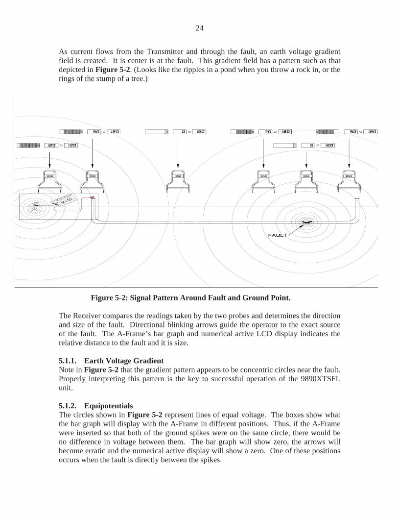
As current flows from the Transmitter and through the fault, an earth voltage gradientfield is created. It is center is at the fault. This gradient field has a pattern such as thatdepicted in Figure 5-2. (Looks like the ripples in a pond when you throw a rock in, or the rings of the stump of a tree.)
Figure 5-2: Signal Pattern Around Fault and Ground Point.
The Receiver compares the readings taken by the two probes and determines the direction and size of the fault. Directional blinking arrows guide the operator to the exact sourceof the fault. The A-Frame s bar graph and numerical active LCD display indicates therelative distance to the fault and it is size.
5.1.1. Earth Voltage GradientNote in Figure 5-2 that the gradient pattern appears to be concentric circles near the fault.Properly interpreting this pattern is the key to successful operation of the 9890XTSFLunit.
5.1.2. EquipotentialsThe circles shown in Figure 5-2 represent lines of equal voltage. The boxes show whatthe bar graph will display with the A-Frame in different positions. Thus, if the A-Framewere inserted so that both of the ground spikes were on the same circle, there would beno difference in voltage between them. The bar graph will show zero, the arrows willbecome erratic and the numerical active display will show a zero. One of these positionsoccurs when the fault is directly between the spikes.

25
This result can also occur midway between the ground spike and a fault and when the A-frame is exactly perpendicular to the fault. There is a return field around the Transmitterground spike. As you move toward the fault, the bars and the active numerical numberwill decrease until you reach the midpoint between the fault and ground spikes. At thehalf waypoint between the fault and ground spike, the signal strength is at it is absolutelowest. At this point the bar graph and active display will show zero and the arrowsbecome erratic.
To determine if you are midway between faults or directly over a fault, move the A-Frame further from the Transmitter and measure again. If the arrows tell you to continuein this direction, the zero point was a midpoint. If the arrows tell you to return toward the Transmitter, the zero point was a fault. As you continue, they will increase until youreach the fault.
Nearly 70% of the signal exists within the last 1/3 of the distance between the groundspike and the fault. The amount of signal measured and displayed by the A-Frame isproportional to the number of field lines in Figure 5-2 between the A-Frame spikes.Thus, the maximum signal point occurs when one A-Frame spike is directly above thefault.
One can learn what to expect the A-Frame response at the fault will be by probing around the ground point. As shown in Figure 5-2, the signal pattern around the fault and groundpoint is identical (if there are no nearby conductors). This means that the A-Frame willreact the same way around the fault as at the ground point.
As you move toward the fault, the bars and the active numerical display will decreaseuntil you reach the midpoint between the fault and ground spike. As you continue, theywill increase until you reach the fault.

26
5.1.3 Multiple Fault PatternsThe signal pattern created by two faults in a line is depicted in Figure 5-3. The twofaults are shown without the ground point. Notice that from a distance the two faults will have the appearance of a single fault due to the equipotential circle around them both. As you get closer, the individual faults become apparent. There is an area between twofaults where the A-Frame may give a false indication of another fault. This is caused bythe two faults canceling each other. Errors can be avoided in this situation by followingthe procedure described in Section 7.7. We recommend that multiple faults be attackedone at a time, i.e., whenever a fault is positively located, it should be repaired beforelooking for the other faults.
F1 F2
Figure 5-3: Multiple Fault Signal Patterns
5.1.4 Distortion Due to Adjacent ConductorsWhenever an un-insulated adjacent conductor lies between a fault and the ground returnpoint; the return current tends to concentrate on the conductor instead of flowing throughthe earth. This can cause shrinkage of the signal pattern near the fault, which would tendto reduce the detectable signal away from the fault. By tracing the faulty conductor firstand looking for adjacent conductors before locating the fault, possible problems such asthis can be avoided.

27
6 Check Out Procedure
Perform this instrument checkout procedure on a lawn prior to field site use. If grass ordirt is not available, indoor carpeting may be used.
1 Check the Batteries.Turn the Transmitter ON . The transmitter LCD will display the battery chargestatus. (If the indicator does not show at least 5 bars replace of recharge thebatteries.) Turn the Transmitter OFF .Turn the A-Frame Receiver ON . The Active and Reference LCD display willshow a battery indication. Each number represents the hours of battery life. If theBA 10 appears, replace the battery (1 ea. 9-volt).
2 Connect the Test Cables.Connect the test cables to the external OUTPUT JACKS. Black cable to blackjack and Red cable to red jack. See Figure 6-1.
Figure 6-1: Checkout Test Set-Up

28
3 Spread the Test Cables as Far Apart as Possible.Insert the ground spike and attach the black cable. Insert a screwdriver into theground and connect the red cable to it. This will create a simulated fault.This test can also be done by pushing the metal end of the clamps directly into the ground so that they make electrical contact.When using a carpet in this checkout procedure connect test cable clamps directlyto the carpet.
4 Turn the Transmitter POWER Knob ONListen for a tone burst and note the indicator for battery condition.
5 Synchronize the Receiver.Hold the A-Frame so the black spike is closest to the ground connection. Push the A-Frame into the ground.
6 Push the Receiver On/Off Switch to ON .The A-Frame Receiver will repeat is battery test. After the battery test, the arrowfacing the simulated fault (red test clamp) flashes and a potential gradient numberis displayed on the Active and Reference LCD display
7 Rotate the A-frame 180 Degrees. Note that the arrow now facing the red test clamp flashes. As the A-Frame is moved around the fault the arrow closest to the simulated fault should flash.

29
7 OPERATION
7.1 Check the batteries prior to going into the field.Follow the Transmitter battery check procedures as given on page 4.
Turn the A-Frame Receiver ON . The battery condition will appear, then diminish. If aBA 10 appears, replace that battery (1each, 9 volt). Turn the Receiver OFF afterchecking the battery.
7.2 Ensure all conductors are de-energized
7.3 Lift the grounds.Lift the grounds (of all conductors in the circuit) at both ends of the faulted cable section.Occasionally, the very experienced fault locators see evidence (i.e. tripped circuitbreakers at transformer) that the fault is so severe that no signal will travel beyond thefault. In these cases, it is not necessary to lift the distant ground.
WARNING!When the Transmitter is set to SFL the external OUTPUT JACK produceup to 1200 volts. Do not touch these jacks, electrical shock will result!
CAUTION!Do not place a shorting bar across external Output Jacks, or connect the twoleads together. Damage to the Transmitter may result.
7.4 Attach the Transmitter to the conductor and check the fault resistance.
1 Turn the Transmitter OFF2 Plug the Black and Red leads into the Transmitter.3 Clamp Red lead to target conductor sheath. Make sure the red clamp does not
make contact with any leaves, grass, or dirt. This could create false reading.4 Stretch Black lead 180 degrees away from the Conductor.5 Push grounding rod into the earth and clamp the Black lead to the grounding rod.
Establish the best ground possible.6 Turn Transmitter Power knob to SFL position. Transmitter will repeat battery
test.7 Check fault resistance. Severe faults read in the 0-100K ohms, medium faults
will read in the 100K 500K ohms, and light faults will read 1 Megohm and up.Turn the frequency knob on the Transmitter to select a tracing frequency. In SFLmode, the Transmitter will simultaneously send 4.8 Hz fault locating frequencyand 9.8 Hz or 82kHz cable tracing frequency.

30
7.5 Synchronize the A-Frame ReceiverBy synchronizing, the A-Frame memorizes the phase of the Transmitter signal.This allows it to recognize the reverse phase signal coming from the fault anddirect you to it.
Note:Resynchronize the Receiver every 45 minutes to maintain calibration. You maydo this near the ground rod or near a fault. At the ground rod, the black A-Framespike must be nearest the ground rod. At a fault, the white A-Frame spike mustbe nearest the fault.
1 Hold the A-Frame so the black spike is closest to the ground rod.2 Push the A-Frame spikes into the ground.3 Switch the Receiver ON . Wait until the arrow flashes.4 If the arrow points away from the ground spike, there is a fault.5 If the arrow points towards the ground spike, there is not fault, or grounds
and connections need to be rechecked. See Figure 7-1.
Figure 7-1: Synchronizing The A-frame

31
Figure 7-2: Fault Confirmation

32
7.6 Confirm that a fault exists.1 Remove the A-Frame from the ground.2 Rotate it 180 degrees and re-insert it into the ground. The arrows should
reverse directions and point away from the ground spike.
7.7 Trace the cable with the 9800XT Receiver.The 9800XT Line Locators allows you to trace the line and search for the fault at thesame time.
1 Check the 9800XT Receiver for cable tracing frequency. Aim theReceiver at the Red lead and cycle through the Receiver frequencies toconfirm that the selected tracing frequency is being received.
2 Trace and mark the cable as you proceed towards the fault.
7.8 Pinpoint the fault.1 Keep the A-Frame parallel to the target cable2 Insert the A-Frame every 10-20 feet. Follow the arrow and monitor the
active number.3 When locating with the A-Frame, make sure that the probes are inserted
well into the ground. A good physical ground connection is needed toreceive strong signal.
4 When the arrow changes direction, back track. Check the active numberand compare it to the reference number. If both active and referencenumbers have the same or similar value, you have found the major fault.
5 Insert the A-Frame every two feet until the arrow changes direction again,then turn it 90 degrees. Check for obvious causes where a fault issuspected, such as recent excavation.
6 Continue to move the A-Frame across the cable until a slight movementcauses the arrow to change directions. When this happens, the fault islocated at the center of the A-Frame.
7.9 Verify the fault.1 Move slightly off to one side of the cable.2 Insert the A-Frame into the ground at various positions around the
suspected fault site (like the hands of a clock).3 The arrow should always point toward the fault.4 Place the other spike in the ground at the fault site and repeat the process.
The arrow should always point inward, toward the faultPlace the other spike in the ground at the fault site and repeat the process. Thearrow should always point inward, toward the fault.

33
8 Advanced Techniques
8.1 Faults Under Inaccessible Surfaces. When the faults exist beneath a paved or other inaccessible area, the fault may be located using one of the following methods.
8.1.1. Perpendicular Method. Carefully trace the location of the faulty conductor. Hold the A-Frame parallel to the cable path. As you move away from the ground rod the bar graph and the active
number will gradually decrease until reaching the midpoint. It will then increase until reaching the fault. When the A-Frame center passes a line perpendicular to the sheath fault, the directional arrow indicators will rapidly change positions and the bar graph and active number will drop to zero. See Figure 8-1.
Paved Surface
Cable Fault
Figure 8-1: Perpendicular Method

34
8.1.2 Triangulation Method.As shown in Figure 8-2, (the point where the signal strength is a minimum) if the A-Frame is positioned exactly on an equipotential circle, a perpendicular line from thecenter of the A-Frame will pass through the fault. The intersection of any two suchperpendicular lines defines the fault location.
Paved Surface
Cable Fault
Figure 8-2: Triangulation Method
To find an equipotential circle (see Figure 8-3) insert the A-Frame into the ground andpivot around one spike. Rotate the A-Frame back and forth until the exact point is foundwhere the flashing arrows change direction. The A-Frame is now on an equipotentialcircle and is perpendicular to the fault. By marking this line and repeating the processwith the A-Frame at another nearby location, the two lines will intersect or cross at thefault.
Figure 8-3: Locating an Equipotential Circle

35
8.2 Faults Under PavementFaults under pavement or other slightly conductive surfaces can be found using the foampads supplied with the unit. Saturate the pads with water and insert the A-Frame spikesinto the pads. Locate the fault as you normally would. Be sure to keep the pads as moistas possible, but do not let the water form a continuous puddle between the pads as thiswill short out the signal.
8.3 Long Distance Tracing.As the distance to the fault increases, the signal picked up by the A-Frame isproportionally reduced. This condition can lead to problems if the signal levels arereduced to the point that they can no longer be detected by the A-Frame.
Whenever working with weak signals due to long distance faults (or other reasons),increased sensitivity can be obtained by extending the distance between the A-Framespikes using the extension cable. This extension method can be applied to any of thepreviously discussed methods including the conductive foam pads. When working withvery long distances, as in fiber optic runs, the sensitivity can be increased even furtherusing a longer insulated wire to extend the A-Frame span. See Figure 8-4.
Figure 8-4: Fault Location Using Extension Cable for Increased Sensitivity

36
High and Low Impedance Faults.Before beginning a fault search it is a good idea to know the severity of the fault. This ismeasured in terms of it is resistance or impedance to ground. Faults where the ground iswet and/or a very large piece of the insulation is missing are found at the low end of therange (<500 ohms). Conditions where the ground is very dry and/or the actual fault is asmall pinhole where the conductor has a very small ground contact area are found at thehigh end of the fault range (>1-3 Meg ohms).
A low impedance fault is the easiest to find since there is more signal to detect.Generally, the more bars and a higher number displayed at synchronization, the larger the fault.
A high impedance fault is more difficult to locate. Characteristically, the Receiver maynot detect the signal after moving a short distance away from the ground point. Thehigher the impedance of the fault, the closer you must be to detect it.
For Example:
If the A-Frame only reliably points away from the ground connection within 10 feet, then the A-frame will only detect the fault within about 10 feet. Outside this distance thesignal is too weak to reliably detect.
For this reason we highly recommend tracing and marking the line before searching outhigh impedance faults.
8.4 Multiple FaultsLocating multiple faults is the most difficult and confusing fault situation. It is especially important in this case to accurately trace the faulty conductor before beginning the faultsearch. Stay exactly above the line if possible and verify each suspected fault bymonitoring the active number to see which fault has the higher number. Remember that a very strong or low impedance fault will mask the detection of a weak or high impedancefault. The safest and best way to find multiple faults is to repair, each fault as it ispositively identified and then continue the search. See Figure 5-3.

37
9 MAINTENANCE
9.1 Receiver Battery Replacement.Loosen the two thumbscrews located on the underside of the Receiver housing. Gentlypull out battery door. Be careful not to pull on the battery wires. Remove battery frombattery holder and disconnect battery. Reverse procedure for installing new battery.
Connector
Figure 9-1: Receiver Battery Replacement

38
9.2 Service CentersIf the instrument does not function properly, replace the battery as described above. Ifthe equipment still malfunctions, contact one of our Metrotech Customer Servicedepartments for assistance:
Metrotech West Coast Service Center 488 Tasman DriveSunnyvale, CA 94043Telephone: 408-730-1400
800-638-7682Fax: 408-734-1415E-mail: [email protected]: www.metrotech.com
Metrotech East Coast Service Center 1824 Murfreesboro Road Suite 104Nashville, TN 37217Telephone: 800-624-6210
615-366-7323Fax: 615-360-9855E-mail: [email protected]
Metrotech Northeast Sales/Service Center89 South Commerce WaySuite 940Bethlehem, PA 18017Telephone: 866-644-8537 610-861-1996Fax: 610-861-1935E-mail: [email protected]: www.metrotech.com
European Service Center Seba DynatronicMess-Und Ortungs-technick GmbHDr. Herbert Iann Str. 6D- 96148 Baunach GermanyTelephone: + 49-9544-680Fax: + 49-9544-2273E-mail: [email protected]: www.sebakmt.com
Or call the factory for the nearest authorized Metrotech repair station.
Additional Metrotech Instruments: Pipe and Cable Locators, Dual Frequency Locators,Magnetic Locators, Fiber Optic Cable Locating System, Leak Detectors, Valve BoxLocators, and High Power Locators.

39
APPENDIX
A1 APWA Marking Colors - The following color markings have been established by the American Public Works Association (APWA):
Conductor ColorElectric power lines, cables, or conduits Red_______________________________________________Communication lines, cables,conduits, CATV Orange_______________________________________________Gas, oil, petroleum, or othergaseous materials Yellow
_______________________________________________Sewers, storm and sanitary, drain lines Green
_______________________________________________Water, irrigation, or slurry lines Blue
Note: If you have any questions regarding marking requirements or procedures in the United States, please call you local One Call Center. International customers: please check with your local regulatory authorities or utility companies required color markings may vary between different countries.

40
COPYRIGHT NOTICE
The information contained in this document is for informational purposes only and issubject to change without notice.Metrotech Corporation makes no warranty of any kind with regard to the informationcontained in this manual, including but not limited to the implied warranties ofmerchantability and fitness for a particular purpose. Metrotech shall not be liable forerrors contained herein, nor for incidental or consequential damages from the furnishingof this information.
This manual contains proprietary information that is protected by copyright. All rightsare reserved. No part of this manual may be photo-copied, reproduced, magneticallystored, transmitted, or translated into another language without the prior written consentof Metrotech Corporation.
Metrotech Corporation 2005

41
WARRANTY
THERE ARE NO WARRANTIES, EXPRESSED OR IMPLIED, INCLUDING ANYWARRANTY OF MERCHANTABILITY, BEYOND THOSE STATED HEREIN.
Metrotech warrants it is equipment to be free from defects in workmanship and materialunder normal and proper use and service for one year from date of purchase by originaluser. Metrotech assumes no obligation to repair or replace equipment which has beenaltered or repaired by other than a Metrotech-approved procedure, been subject to misuse, misapplication, improper maintenance, negligence, or accident; has had it is serialnumber or any part here of altered, defaced ore removed; or been used with parts otherthan those approved by Metrotech. Warranty does not include batteries. Expendableitems such as fuses and lamps are excluded.
Any detection product proved defective under this warranty will be repaired or replacedfree or charge at the Metrotech Corporation factory or approved Metrotech repair station.The equipment should be returned to our factory by prepaid transportation afterrequesting and receiving return authorization from our Service Department.
Metrotech s obligations are limited to repair or replacement of broken or defective parts,which have not been abused, misused, altered, or accidentally damaged, or at the optionof Metrotech, to refund of the purchase price. Metrotech assumes no liability for removal or installation costs, consequential damages, or contingent expenses of any other nature.
Part #: 10877Price: $10.00 US