Shear Strength of Reactive Resistance Welded Ti6Al4V Parts … · The results of shear tests showed...
5
Shear Strength of Reactive Resistance Welded Ti6Al4V Parts with the Use of Ni(V)/Al Multilayers ŁUKASZ MAJ, JERZY MORGIEL, KRZYSZTOF MARS, ANNA TARASEK, and EL _ ZBIETA GODLEWSKA The Ti6Al4V/(Ni/Al)/Ti6Al4V joints were obtained through reactive resistance welding which takes advantage of electric current heating to initiate the rapid exothermic reaction of Ni(V)/Al multilayers and activate diffusion of elements across the Ni/Al-Ti6Al4V interfaces. Simulations of temperature distribution, carried out using COMSOL Ò software, showed temperature gradient in the joint being a result of differences in resistivity of the Ti6Al4V alloy and the (Ni/ Al)/Ti6Al4V interface. Shear tests revealed that extending duration of the process from 2 to 6 minutes helped to improve the shear strength from ~ 240 to ~ 335 MPa. The microstructure observations of the samples after those tests showed that de-cohesion of the joint occurred along the filler material/base material interface. A microcrack network characteristic for reacted Ni/Al foil with small ridges was found on the flat surfaces of fractured samples. https://doi.org/10.1007/s11661-018-4843-5 Ó The Author(s) 2018 I. INTRODUCTION WELDING of titanium-based alloys, like a Ti6Al4V, poses a significant challenge due to a high affinity of titanium for oxygen as well as its high melting temper- ature. The former may be overcome by applying an argon protective atmosphere, while the latter by a local heating with an electron or a laser beam. [1] The strength of obtained joint is therefore compromised not only by a coarse grain present in melted and solidified material, but also by a large heat-affected zone softened by recovery processes. On the other hand, diffusion brazing process is most frequently performed at temperature below the a fi b transition at ~ 1000 °C. [2] However, it requires relatively long processing times necessary to activate the solid-state diffusion across the interface between filler material and base material. [3] Therefore, new alternative techniques of joining titanium alloys are still sought. Reactive metallic multilayer foils, releasing a large amount of heat during self-propagating high-tempera- ture synthesis (SHS), open new possibilities in joining materials. Initiated by an external energy pulse, they produce fast local temperature raise (even up to 1500 °C for the Ni(V)/Al system [4] ) and results in the melting of at least one of reactants. However, the heat released at fast moving SHS front is insufficient to melt surfaces to be joined. Up till now, obtaining a firm connection with the use of reactive multilayers has been possible only either through deposition of an additional braze alloy coating [5] or by supporting the heat pulse produced during SHS reaction in other ways. [6] The approach taking advantage of braze alloy good wetting properties has been already applied by commercializing NanoFoil Ò product. It consists of freestanding Ni(V)/Al multilayer foil covered with Incusil TM (Ag-Cu-In-Ti) alloy Ignited Ni(V)/Al multilayer releases enough heat to melt the Ag-Cu-In-Ti layer, securing good wetting of pieces of titanium alloy. It was reported that such a joint can be obtained in a very short time, but its shear strength barely reaches ~ 40 MPa. [5] The other way is realized by passing strong electric currents through elements to be joined with multilayers, what helps to attain high-tem- perature activating diffusion processes necessary for good connection. Therefore, this joining process is called a ‘reactive resistance welding’ (RRW). Although not fully worked out as yet, theoretically it should secure not only fast but also much stronger connection, compared with the brazing technique. The RRW method was originally applied to join elements made of refractory metals, including tungsten and tantalum with the use of reactive powders ignited with a pulse of 1000 A electric current. [7] However, due to problems with handling of powders and their spreading in a layer of same thickness, new filler materials like Ni/Al multilayers are tried. [6] Application ŁUKASZ MAJ, JERZY MORGIEL, and ANNA TARASEK are with the Institute of Metallurgy and Materials Science, Polish Academy of Sciences, 25 Reymonta St., 30-059 Krako´w, Poland. Contact e-mail: [email protected] KRZYSZTOF MARS and EL _ ZBIETA GODLEWSKA are with the Faculty of Materials Science and Ceramics, AGH University of Science and Technology, 30-059 Krako´w, Poland. Manuscript submitted February 23, 2018. Article published online July 27, 2018 METALLURGICAL AND MATERIALS TRANSACTIONS A VOLUME 49A, NOVEMBER 2018—5423
Transcript of Shear Strength of Reactive Resistance Welded Ti6Al4V Parts … · The results of shear tests showed...

Shear Strength of Reactive Resistance WeldedTi6Al4V Parts with the Use of Ni(V)/Al Multilayers
ŁUKASZ MAJ, JERZY MORGIEL, KRZYSZTOF MARS, ANNA TARASEK,and EL _ZBIETA GODLEWSKA
The Ti6Al4V/(Ni/Al)/Ti6Al4V joints were obtained through reactive resistance welding whichtakes advantage of electric current heating to initiate the rapid exothermic reaction of Ni(V)/Almultilayers and activate diffusion of elements across the Ni/Al-Ti6Al4V interfaces. Simulationsof temperature distribution, carried out using COMSOL� software, showed temperaturegradient in the joint being a result of differences in resistivity of the Ti6Al4V alloy and the (Ni/Al)/Ti6Al4V interface. Shear tests revealed that extending duration of the process from 2 to6 minutes helped to improve the shear strength from ~ 240 to ~ 335 MPa. The microstructureobservations of the samples after those tests showed that de-cohesion of the joint occurred alongthe filler material/base material interface. A microcrack network characteristic for reacted Ni/Alfoil with small ridges was found on the flat surfaces of fractured samples.
https://doi.org/10.1007/s11661-018-4843-5� The Author(s) 2018
I. INTRODUCTION
WELDING of titanium-based alloys, like a Ti6Al4V,poses a significant challenge due to a high affinity oftitanium for oxygen as well as its high melting temper-ature. The former may be overcome by applying anargon protective atmosphere, while the latter by a localheating with an electron or a laser beam.[1] The strengthof obtained joint is therefore compromised not only by acoarse grain present in melted and solidified material,but also by a large heat-affected zone softened byrecovery processes. On the other hand, diffusion brazingprocess is most frequently performed at temperaturebelow the a fi b transition at ~ 1000 �C.[2] However, itrequires relatively long processing times necessary toactivate the solid-state diffusion across the interfacebetween filler material and base material.[3] Therefore,new alternative techniques of joining titanium alloys arestill sought.
Reactive metallic multilayer foils, releasing a largeamount of heat during self-propagating high-tempera-ture synthesis (SHS), open new possibilities in joiningmaterials. Initiated by an external energy pulse, they
produce fast local temperature raise (even up to 1500 �Cfor the Ni(V)/Al system[4]) and results in the melting ofat least one of reactants. However, the heat released atfast moving SHS front is insufficient to melt surfaces tobe joined. Up till now, obtaining a firm connection withthe use of reactive multilayers has been possible onlyeither through deposition of an additional braze alloycoating[5] or by supporting the heat pulse producedduring SHS reaction in other ways.[6] The approachtaking advantage of braze alloy good wetting propertieshas been already applied by commercializing NanoFoil�
product. It consists of freestanding Ni(V)/Al multilayerfoil covered with IncusilTM (Ag-Cu-In-Ti) alloy IgnitedNi(V)/Al multilayer releases enough heat to melt theAg-Cu-In-Ti layer, securing good wetting of pieces oftitanium alloy. It was reported that such a joint can beobtained in a very short time, but its shear strengthbarely reaches ~ 40 MPa.[5] The other way is realized bypassing strong electric currents through elements to bejoined with multilayers, what helps to attain high-tem-perature activating diffusion processes necessary forgood connection. Therefore, this joining process iscalled a ‘reactive resistance welding’ (RRW). Althoughnot fully worked out as yet, theoretically it should securenot only fast but also much stronger connection,compared with the brazing technique.The RRW method was originally applied to join
elements made of refractory metals, including tungstenand tantalum with the use of reactive powders ignitedwith a pulse of 1000 A electric current.[7] However, dueto problems with handling of powders and theirspreading in a layer of same thickness, new fillermaterials like Ni/Al multilayers are tried.[6] Application
ŁUKASZ MAJ, JERZY MORGIEL, and ANNA TARASEK arewith the Institute of Metallurgy and Materials Science, PolishAcademy of Sciences, 25 Reymonta St., 30-059 Krakow, Poland.Contact e-mail: [email protected] KRZYSZTOF MARS andEL _ZBIETA GODLEWSKA are with the Faculty of MaterialsScience and Ceramics, AGH University of Science and Technology,30-059 Krakow, Poland.
Manuscript submitted February 23, 2018.Article published online July 27, 2018
METALLURGICAL AND MATERIALS TRANSACTIONS A VOLUME 49A, NOVEMBER 2018—5423

of the reactive multilayers instead of powders not onlyallowed to reduce the thickness of the filler materialfrom ~ 1 mm to< 100 lm, but also to lower the electriccurrent down to 400 A. Simultaneously, it helped toalleviate the high-temperature exposure of the joinedelements. Microstructure and hardness of the Ti6Al4V/NiAl/Ti6Al4V joints after 2, 4, and 6 minutes ofprocessing time were already described,[8] but no mea-surements of their strength were reported as yet.
Therefore, the main objective of the present study wasto investigate the shear strength and topography frac-ture of Ti6Al4V parts joined with Ni(V)/Al multilayersby the RRW method. The microstructure observationsof fractured surfaces were carried out with the use ofscanning electron microscopy (SEM).
II. MATERIALS AND METHODS
The two-phase (a+ b) Ti6Al4V alloy was cut into5 mm 9 5 mm 9 3 mm platelets with a diamond wiresaw. Freestanding Ni(V)/Al multilayer foils with anominal period of K = 50 nm and overall thickness of60 lm were used as a filler material. All samples wereground and polished with abrasive papers and colloidalsilica suspension, respectively.
A dedicated stand described in detail elsewhere[6] wasused in the RRW joining experiments. Each Ti6Al4V/(Ni/Al)/Ti6Al4V stack was placed in a chamber (evac-uated down to 10�1 mbar) between steel staples under aload of 100 MPa. A DC current of 400 A was passedthrough the samples for 2, 4, and 6 minutes. Thetemperature of the joint was measured using a type-Kthermocouple (/ ~ 0.5 mm). The temperature gradientin the joint area was simulated with the help ofCOMSOL� software, with the input data being theresistivity of the Ti6Al4V alloy (qTi6Al4V = 1.78 910�6 X m) and the measured resistivity of theTi6Al4V/NiAl interface (qTi6Al4V/NiAl-interface = 5 910�5 X m).
Shear strength of the obtained joints was examined ina static axial compression test on INSTRON 3382testing machine using a die dedicated for small samplesas presented in Figure 1(a). The hardened low-carbonsteel die (50 9 50 9 30 mm) had two channels. Thevertical channel served as a guiderail for the steel staple,while the short horizontal (4 9 4 mm) one helped to fixthe Ti6Al4V/(Ni/Al)/Ti6Al4V joint (Figure 1(b)). Theshear strength measurements were carried out at roomtemperature (22 �C) at a crosshead speed of 0.2 mm/min. For each bonding time, five samples were tested.The microstructure observations of fractured samples
after shear test were carried out with the use of PhilipsXL30 scanning electron microscope operating at 30 kVin backscattered (BSE) and secondary electrons (SE)modes in order to obtain an information about the crackpath and the fractured surface topography, respectively.
III. RESULTS
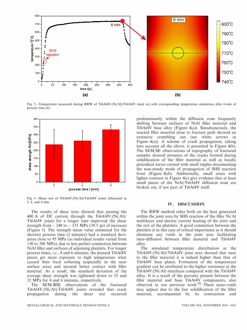
Temperature in the middle of the Ti6Al4V/(Ni/Al)/Ti6Al4V joint was approximated by a signal averagedfrom an area of ~ 0.5 mm in diameter (as marked bydashed circle in Figure 2(b)). A flow of 400 A DCcurrent resulted in a fast temperature raise up to~ 700 �C within 30 seconds and initiation of the SHSreaction already at ~ 240 �C, which is evidenced both bythe presence of a small hump on the temperature vs. timecurve and simultaneous emission of a bright orange lightin the Ni(V)/Al multilayer foil. Extending the RRWtime to 6 minutes caused slow increase of the maximumattained temperature up to ~ 760 �C. Simulations,taking into account exclusively the effect of currentflow, revealed that the highest temperature is reached atthe joint center with a steep gradient on both sides(Figure 2(b)). The obtained results indicated that thefiller material was heated up to ~ 800 �C, whereas thetemperature of the joined elements was lower than770 �C at a distance exceeding 0.5 mm.
Fig. 1—Image of a die used in shear strength measurements (a) and its dimensions in mm (b).
5424—VOLUME 49A, NOVEMBER 2018 METALLURGICAL AND MATERIALS TRANSACTIONS A
The results of shear tests showed that passing the400 A of DC current through the Ti6Al4V/(Ni/Al)/Ti6Al4V joints for a longer time improved the shearstrength from ~ 240 to ~ 335 MPa (39.5 pct of increase)(Figure 3). The strength mean value estimated for theshortest process time (2 minutes) had a standard devi-ation close to 95 MPa (as individual results varied from130 to 380 MPa), due to less perfect connection betweenNiAl filler and surfaces of adjoining platelets. For longerprocess times, i.e., 4 and 6 minutes, the pressed Ti6Al4Vpieces get more exposure to high temperature whatcaused their local softening (especially in the nearsurface area) and secured better contact with fillermaterial. As a result, the standard deviation of theaverage shear strength was tightened down to 55 and32 MPa for 4 and 6 minutes, respectively.
The SEM/BSE observations of the fracturedTi6Al4V/(Ni/Al)/Ti6Al4V joints revealed that crackpropagation during the shear test occurred
predominantly within the diffusion zone frequentlyshifting between surfaces of NiAl filler material andTi6Al4V base alloy (Figure 4(a)). Simultaneously, thereacted filler material close to fracture path showed anextensive crumbling out (see white arrows inFigure 4(a)). A scheme of crack propagation, takinginto account all the above, is presented in Figure 4(b).The SEM/SE observations of topography of fracturedsamples showed presence of the cracks formed duringsolidification of the filler material as well as locallyperiodical waves crested with small ripples documentingthe non-steady mode of propagation of SHS reactionfront (Figure 4(d)). Additionally, small areas withlighter contrast in Figure 4(c) give evidence that at leastsmall pieces of the NiAl/Ti6Al4V diffusion zone arebroken out, if not part of Ti6Al4V itself.
IV. DISCUSSION
The RRW method relies both on the heat generatedwithin the joint area by SHS reaction of the filler Ni/Almultilayer and electric current heating of the joint andthe rest of the platelets. A good connection between theplatelets is in this case of critical importance as it shouldeliminate any voids in the joint area facilitatinginter-diffusion between filler material and Ti6Al4Valloy.The simulated temperature distribution at the
Ti6Al4V/(Ni/Al)/Ti6Al4V joint area showed that nearto the filler material it is indeed higher than that ofTi6Al4V base plates. Formation of the temperaturegradient can be attributed to the higher resistance at theTi6Al4V/(Ni/Al) interfaces compared with the Ti6Al4Valloy. It is a result of the porosity present between thefiller material and base Ti6Al4V components, alsoobserved in our previous work.[8] These nano-voidsmay appear due to the fast solidification of the fillermaterial, accompanied by its contraction and
Fig. 2—Temperature measured during RRW of Ti6Al4V/(Ni/Al)/Ti6Al4V stack (a) with corresponding temperature simulation after 6 min ofprocess time (b).
Fig. 3—Shear test of Ti6Al4V/(Ni/Al)/Ti6Al4V joints fabricated in2, 4, and 6 min.
METALLURGICAL AND MATERIALS TRANSACTIONS A VOLUME 49A, NOVEMBER 2018—5425

macroscopic shape change. Thus, even a large loadapplied to the Ti6Al4V/(Ni/Al)/Ti6Al4V stack duringjoining process may not provide a full matching betweenjoined surfaces. Simultaneously, the temperature of thejoining process controlled by electric current was soadjusted as to not exceed the temperature of a fi btransition (~ 1000 �C) in Ti6Al4V alloy, i.e., in order topreserve its initial mechanical properties. In case offriction welded Ti6Al4V parts even area 1 mm awayfrom the weld interface may be affected by a tempera-ture exceeding 1000 �C, significantly changing themicrostructure and degrading mechanical properties ofobtained joint.[9] On the other hand, diffusion bondingof TiAl alloys with the Ni(V)/Al multilayers reactionproceeded through solid state diffusion.[10,11] This pro-cess, carried out in vacuum furnace, results in uniformheating of all components to be joined. However, theheat of exothermic reaction of Ni(V)/Al multilayers ispractically lost due to long processing time. In view ofabove, the RRW is a unique process capable ofproducing a temperature gradient utilizing all availableheat sources exactly in the most needed area. In thisway, it accelerates the diffusion in the joint with
simultaneous preserving mechanical properties of basematerial as presented in Reference 8.Mechanical properties of the joints are evaluated
mostly through their shear strength. Present experimentsshowed that the maximum strength of Ti6Al4V/(Ni/Al)/Ti6Al4V joints reaches ~ 380 MPa. The main cause offailure of produced joints, especially those obtainedafter shortest processing time (2 minutes) were the stillnumerous voids present at the interface betweenTi6Al4V alloy and SHS-reacted Ni/Al multilayer. Forthe longer times, local flow of the Ti6Al4V plateletshelps to close at least some of these defects, whatexplains the rise of the shear strength. The lattermeasured for RRW joined Ti6Al4V/(Ni/Al)/Ti6Al4Vparts turns out to be ~ 10 times higher than for similarjoints obtained with NanoFoil� brazing initiated byshort current pulse (9 V/~ 1 s),[5] i.e., practically withoutany additional heating. However, diffusion bonding oftitanium alloys using Ni/Al multilayers indicates thatshear strength higher than 300 MPa is achievable onlywhen the processing time is relatively long (> 60 min-utes).[10] It indicates that the RRW process has anadvantage in time-temperature scale over the currently
50 m
Ti6Al4VTi6Al4V transformedNi/Al multilayer
diffusion zonefracture
path
(a) (b)
200 m
(c)
100 m
(d)
Fig. 4—SEM/BSE image of section of fractured Ti6Al4V/(Ni/Al)/Ti6Al4V joint after shear strength test (a), scheme of fracture path (b), andSEM/SE images of surface topography of fractured joints (c, d) (white arrows in (a) point out to crumbled out material).
5426—VOLUME 49A, NOVEMBER 2018 METALLURGICAL AND MATERIALS TRANSACTIONS A

applied methods of materials joining with the use ofreactive Ni/Al multilayers.
The knowledge of crack propagation path and thecharacteristic features of fractured surfaces in the jointusually help both to classify the formed connections aswell as to improve their strength. Shearing forcesapplied to Ti6Al4V/(Ni/Al)/Ti6Al4V joint resulted intheir failure within the diffusion zone formed betweenTi6Al4V base material and reacted multilayer foil, i.e.,one of the most frequent cases for welded material.However, in case of presently investigated RRW jointsmost of flat cleavage areas are crisscrossed with a set ofperpendicular cracks resulting from the shrinkageoccurring during NiAl solidification. The areas locatednear the cracked edges carried patches of materialevidently differing in contrast, which have been pulledout from diffusion zone or even from the Ti6Al4V alloy.All of it indicates a quasi-brittle cracking mode, bearingalso features of some plastic deformation. The observa-tions carried out by Simoes et al.[10] for diffusion bondedTiAl alloys revealed that the joint characterized by astrength of ~ 300 MPa cracked in similar way, exceptfor the lack of the network of perpendicular cracks,which is specific for Ni(V)/Al multilayers reacted bySHS. The results obtained for other methods of joiningof Ti6Al4V alloys like laser beam welding with niobiuminterlayer revealed fully brittle cracking during sheartests being a consequence of hydrogen and oxygencontamination of weld pool.[12] The RRW joining ofTi6Al4V parts with Ni/Al multilayers as a filler material,carried out at the temperatures below a fi b transitionpoint for Ti6Al4V alloy, results in significant decrease ofthe contamination level as compared with weldingtechniques.
V. CONCLUSIONS
The RRW joining of elements made of Ti6Al4V usingNi(V)/Al multilayers as a filler material was successfullyperformed by maintaining a DC electric current of400 A for at least a few minutes. The following sheartests supported by detailed microstructure observationsof the fractured samples allowed to conclude that:
1. Shear strength of the Ti6Al4V/(Ni/Al)/Ti6Al4Vjoints increased from ~ 240 to ~ 335 MPa as theRRW time was extended from 2 to 6 minutes.
2. De-cohesion of the Ti6Al4V/(Ni/Al)/Ti6Al4V jointsduring shear stress test occurred within the diffusionzone between the NiAl filler and the Ti6Al4V basealloy.
3. Fracture surfaces of the shear tested samples showmostly flat surfaces with minor amount of materialpulled out from the adjacent Ti6Al4V platelets,evidencing a quasi-brittle cracking with some con-tribution of plastic deformation.
The mechanical and microstructure data obtained inthis work demonstrate that the RRW method proposedfor joining of TiAl4V components is capable of pro-ducing strong joints in relatively short time.
ACKNOWLEDGMENTS
The investigations were financially supported by thestatutory funds of Institute of Metallurgy and Materi-als Science, PAS (Z-14) and AGH UST No.11.11.160.438. Microstructure investigations andmechanical tests were performed in the AccreditedTesting Laboratories at the Institute of Metallurgyand Materials Science, PAS. The reactive resistive join-ing experiments were done at the Functional CoatingsLab, Faculty of Materials Science and Ceramics, AGHUST.
OPEN ACCESS
This article is distributed under the terms of theCreative Commons Attribution 4.0 InternationalLicense (http://creativecommons.org/licenses/by/4.0/),which permits unrestricted use, distribution, andreproduction in any medium, provided you giveappropriate credit to the original author(s) and thesource, provide a link to the Creative Commonslicense, and indicate if changes were made.
REFERENCES1. Y. Deng, Q. Guan, B. Wu, and J. Tao: Vacuum, 2015, vol. 117,
pp. 17–22.2. S. Jidhav, A. Powar, S. Patil, A. Supare, B. Farane, and R. Singh:
IOP Conf. Series, 2017, vol. 201, p. 012035.3. F.A. Calvo, J.M. Gomez de Salazar, D. Urena, J.G. Carrion, and
F. Perosanz: J. Mater. Sci., 1992, vol. 27, pp. 391–98.4. D.P. Adams: Thin Solid Films, 2015, vol. 576, pp. 98–128.5. A. Duckham, S.J. Spey, J. Wang, M.E. Reiss, T.P. Weihs, E.
Besnoin, and O.M. Knio: J. Appl. Phys., 2004, vol. 96 (4),pp. 2336–42.
6. Ł. Maj, K. Mars, J. Morgiel, and E. Godlewska: Phys. Stat. Solidi,2017, vol. 11 (2), p. 1600405.
7. A.S. Mukasyan and J.D.E. White: Int. J. SHS, 2007, vol. 16 (3),pp. 154–68.
8. Ł. Maj, J. Morgiel, K. Mars, J. Grzegorek, M. Faryna, and E.Godlewska: J. Mater. Process. Technol., 2018, vol. 255,pp. 689–95.
9. A.R. McAndrew, P.A. Colegrove, C. Buhr, B.C.D. Flipo, and A.Vairis: Progr. Mater. Sci., 2018, vol. 92, pp. 225–57.
10. S. Simoes, F. Viana, V. Ventzke, M. Kocak, A.S. Ramos, M.T.Vieira, and M.F. Vieira: J. Mater. Sci., 2010, vol. 45, pp. 4351–57.
11. S. Simoes, F. Viana, and M.F. Vieira: J. Mater. Eng. Perform.,2014, vol. 23, pp. 1536–43.
12. J.P. Oliveira, B. Panton, Z. Zeng, C.M. Andrei, Y. Zhou, R.M.Miranda, and F.M. Braz Fernandes: Acta Mater., 2016, vol. 105,pp. 9–15.
METALLURGICAL AND MATERIALS TRANSACTIONS A VOLUME 49A, NOVEMBER 2018—5427