SHARKY 775 Ultrasonic Compact Energy Meter Sharky775... · HYDROMETER GmbH Industriestraße 13 ·...
59
HYDROMETER GmbH Industriestraße 13 · 91522 Ansbach · Telefon +49 (981) 18 06 - 0 · Telefax +49 (981) 18 06 – 615 Am Weimarer Berg 3 · 99510 Apolda/Thüringen · Telefon +49 (3644) 84 33 - 0 · Telefax +49 (3644) 84 33 - 411 [email protected] · www.hydrometer.de · Subject to technical adjustments · Version 1.6 ·12.07.2012 for Software Version F01-001 1 SHARKY 775 Ultrasonic Compact Energy Meter Installation and User Guide for software version F01-001
Transcript of SHARKY 775 Ultrasonic Compact Energy Meter Sharky775... · HYDROMETER GmbH Industriestraße 13 ·...
HYDROMETER GmbH
Industriestraße 13 · 91522 Ansbach · Telefon +49 (981) 18 06 - 0 · Telefax +49 (981) 18 06 – 615
Am Weimarer Berg 3 · 99510 Apolda/Thüringen · Telefon +49 (3644) 84 33 - 0 · Telefax +49 (3644) 84 33 - 411
[email protected] · www.hydrometer.de · Subject to technical adjustments · Version 1.6 ·12.07.2012 for Software Version F01-001
1
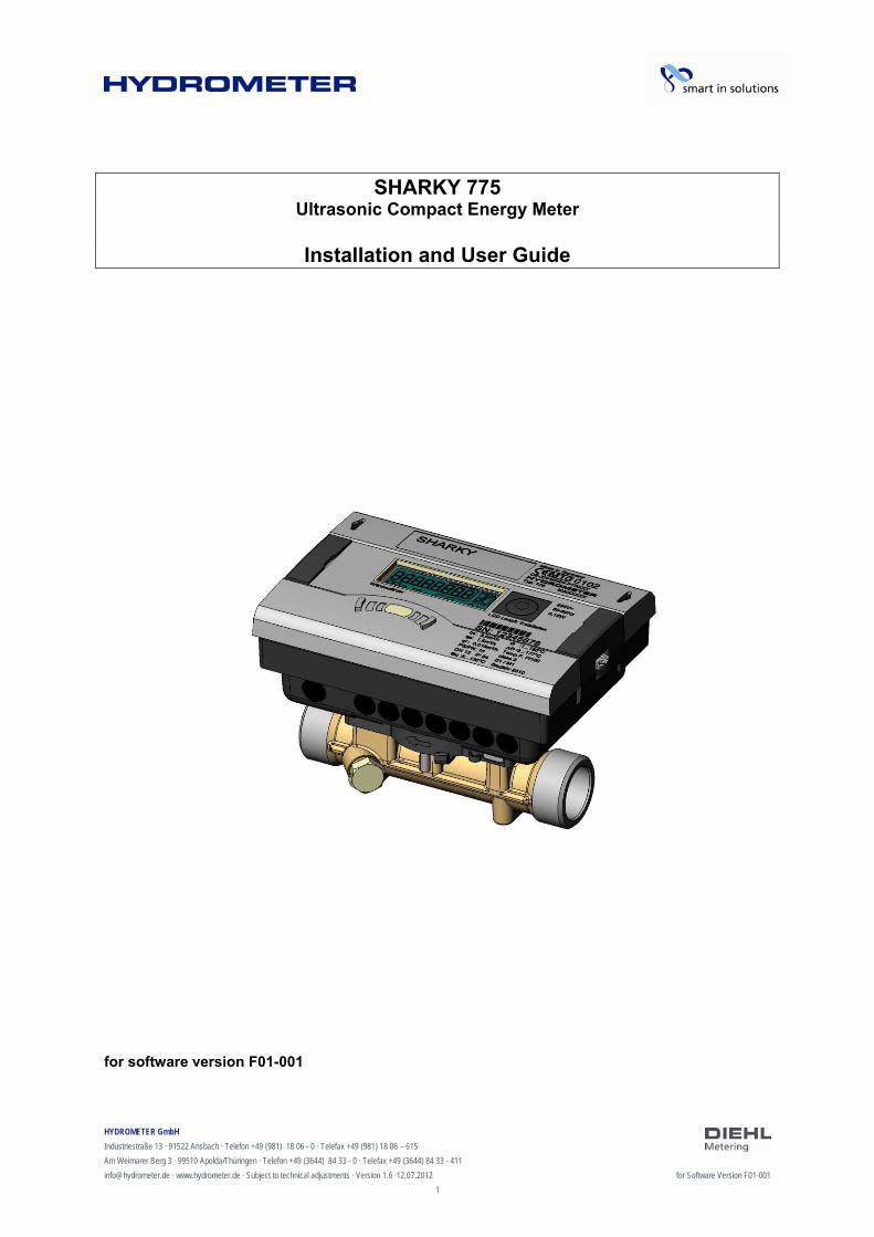
SHARKY 775 Ultrasonic Compact Energy Meter
Installation and User Guide
for software version F01-001

HYDROMETER GmbH
Industriestraße 13 · 91522 Ansbach · Telefon +49 (981) 18 06 - 0 · Telefax +49 (981) 18 06 – 615
Am Weimarer Berg 3 · 99510 Apolda/Thüringen · Telefon +49 (3644) 84 33 - 0 · Telefax +49 (3644) 84 33 - 411
[email protected] · www.hydrometer.de · Subject to technical adjustments · Version 1.6 ·12.07.2012 for Software Version F01-001
2
Contents
1 General................................................................................................. 4
1.1 About this Installation and User Guide ...................................... 4 1.1.1 Target groups ............................................................................4 1.1.2 Subject to change, validity .........................................................4 1.1.3 Completeness............................................................................4 1.1.4 Storage location.........................................................................4 1.1.5 Warning signs ............................................................................4 1.1.6 Symbols .....................................................................................5
1.2 Marking ...................................................................................... 5 1.2.1 CE marking ................................................................................5 1.2.2 EC declaration of conformity......................................................5
1.3 Copyright.................................................................................... 5
2 Safety ................................................................................................... 6
2.1 Intended use .............................................................................. 6 2.1.1 Misuse .......................................................................................6
2.2 Basic safety instructions ............................................................ 6 2.2.1 Product safety............................................................................6 2.2.2 Obligations of operator ..............................................................6 2.2.3 Obligations of trained personnel/user ........................................7
2.3 Specific hazards......................................................................... 7
3 Product description............................................................................... 8
3.1 Mechanical design ..................................................................... 8 3.2 Scope of delivery ....................................................................... 8 3.4 Functional description ................................................................ 9 3.5 Power supply............................................................................ 10
3.5.1 Battery .....................................................................................11 3.5.2 Overview of the measuring rates .............................................11 3.5.3 Mains unit ................................................................................12
3.6 Calculator interfaces ................................................................ 12 3.6.1 Communication modules .........................................................13 3.6.2 Function modules ....................................................................14
4 Technical data .................................................................................... 15
4.1 Dimensions/weight................................................................... 15 4.2 General data ............................................................................ 17 4.3 Power supply............................................................................ 17 4.4 Calculator interfaces ................................................................ 17
4.4.1 Communication modules .........................................................17 4.4.2 Function modules ....................................................................19 4.4.3 Test output...............................................................................23
5 Transport, storage.............................................................................. 24
5.1 Unpacking the energy meter.................................................... 24
HYDROMETER GmbH
Industriestraße 13 · 91522 Ansbach · Telefon +49 (981) 18 06 - 0 · Telefax +49 (981) 18 06 – 615
Am Weimarer Berg 3 · 99510 Apolda/Thüringen · Telefon +49 (3644) 84 33 - 0 · Telefax +49 (3644) 84 33 - 411
[email protected] · www.hydrometer.de · Subject to technical adjustments · Version 1.6 ·12.07.2012 for Software Version F01-001
3
5.2 Transporting the energy meter................................................. 24 5.3 Storage of energy meter .......................................................... 24
6 Installation .......................................................................................... 25
6.1 Installing the energy meter....................................................... 26 6.1.1 Installing the flow sensor..........................................................27 6.1.2 Installing the calculator ............................................................28 6.1.3 Connecting temperature sensor...............................................30 6.1.4 Installing the temperature sensors...........................................31
6.2 Installing extension modules.................................................... 33 6.2.1 Display of the slot configuration ...............................................36
6.3 Connecting modules ................................................................ 37 6.3.1 Connecting communication modules .......................................37 6.3.2 Connecting function modules...................................................38
6.4 Connecting the mains voltage 230 V / 24 V............................. 39 6.5 Programming the energy meter ............................................... 40
7 Taking into operation.......................................................................... 41
8 Operation............................................................................................ 42
8.1 Display ..................................................................................... 42 8.2 Operation of meter ................................................................... 42 8.3 Display indications (default settings) ....................................... 44
9 Maintenance and repair ..................................................................... 54
10 Testing................................................................................................ 55
11 Removal ............................................................................................. 56
11.1 Disposal of energy meter ......................................................... 56
12 Error analysis ..................................................................................... 57
13 Declaration of conformity ................................................................... 58
HYDROMETER GmbH
Industriestraße 13 · 91522 Ansbach · Telefon +49 (981) 18 06 - 0 · Telefax +49 (981) 18 06 – 615
Am Weimarer Berg 3 · 99510 Apolda/Thüringen · Telefon +49 (3644) 84 33 - 0 · Telefax +49 (3644) 84 33 - 411
[email protected] · www.hydrometer.de · Subject to technical adjustments · Version 1.6 ·12.07.2012 for Software Version F01-001
4
1 General
1.1 About this Installation and User Guide
This Installation and User Guide refers exclusively to the SHARKY 775 ultrasonic energy meter and is part of the product. It describes how to use this product safely for the intended purpose throughout the product life cycle.
1.1.1 Target groups
Operators
The operator must ensure that personnel using the energy meter read and observe the instructions given in this guide and all necessary associated documents, particularly the safety instructions and warning signs.
Trained personnel/users
Trained personnel must read, observe and follow the instructions given in this guide and the necessary associated documents, particularly the safety instructions and warning signs.
1.1.2 Subject to change, validity
The information contained in this Installation and User Guide is valid at the time of release of this version. The version number and release date of this Installation and User Guide are shown on the back of the document. Changes to this guide are possible at any time.
1.1.3 Completeness
This Installation and User Guide is only complete in conjunction with the relevant associated documents for the respective application.
1.1.4 Storage location
This Installation and User Guide and all relevant associated documents for the respective application must be readily available and accessible at all times in the vicinity of the meter or the overriding system.
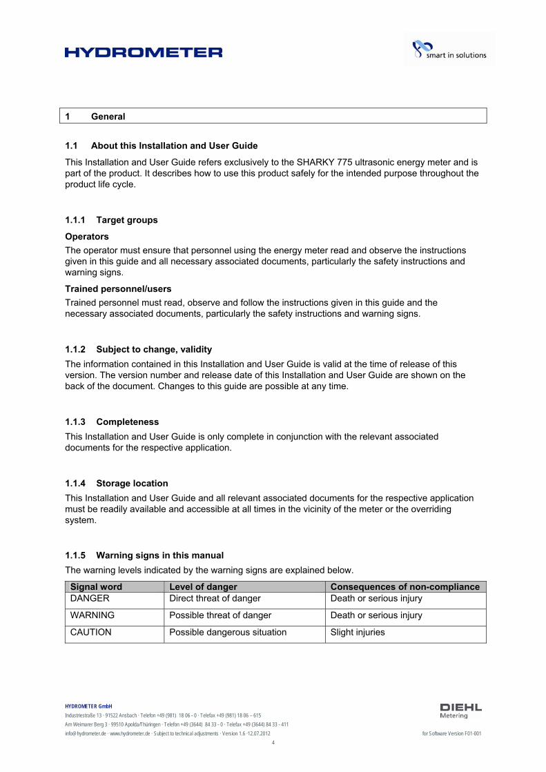
1.1.5 Warning signs in this manual
The warning levels indicated by the warning signs are explained below.
Signal word Level of danger Consequences of non-compliance DANGER Direct threat of danger Death or serious injury
WARNING Possible threat of danger Death or serious injury
CAUTION Possible dangerous situation Slight injuries

HYDROMETER GmbH
Industriestraße 13 · 91522 Ansbach · Telefon +49 (981) 18 06 - 0 · Telefax +49 (981) 18 06 – 615
Am Weimarer Berg 3 · 99510 Apolda/Thüringen · Telefon +49 (3644) 84 33 - 0 · Telefax +49 (3644) 84 33 - 411
[email protected] · www.hydrometer.de · Subject to technical adjustments · Version 1.6 ·12.07.2012 for Software Version F01-001
5
1.1.6 Symbols
The symbols used in this Installation and User Guide are explained below.
Symbol Meaning
This symbol is the safety sign. All measures marked with the safety sign must be observed. It is used on warning signs.
This symbol is a safety sign indicating that the ESD (electrostatic discharge) regulations must be observed. It is used on warning signs.
This symbol draws attention to information.
This symbol indicates a requirement that must be fulfilled before taking action.
1. , 2. , … These numbers indicate the steps in a sequence of numbered actions.
This symbol shows the instructions for avoiding danger in a warning instruction or an individual step.
1.2 Marking
1.2.1 CE marking
This product bears the CE marking, the metrology marking and the identification number of the notified body. See Section 3.
1.2.2 EC declaration of conformity
The ultrasonic energy meter complies with the directives and standards for MID-approved meters as stated in the EC declaration of conformity. The EC declaration of conformity contains the number of the EC type examination certificate. A copy of the EC declaration of conformity can be found at the end of this document.
1.3 Copyright
© 2012 Hydrometer GmbH
All rights reserved.
No part of this Installation and User Guide may be reproduced in any form whatsoever (printing, photocopying or other process) or processed, reproduced or distributed by means of electronic systems without our written consent. Claims for damages will be asserted in the event of contravention.
Subject to change.
HYDROMETER GmbH
Industriestraße 13 · 91522 Ansbach · Telefon +49 (981) 18 06 - 0 · Telefax +49 (981) 18 06 – 615
Am Weimarer Berg 3 · 99510 Apolda/Thüringen · Telefon +49 (3644) 84 33 - 0 · Telefax +49 (3644) 84 33 - 411
[email protected] · www.hydrometer.de · Subject to technical adjustments · Version 1.6 ·12.07.2012 for Software Version F01-001
6
2 Safety
NOTE
Observe the following requirements before carrying out work of any kind.
2.1 Intended use
The ultrasonic energy meter is used for recording all billing data for local and district heating and cooling.
2.1.1 Misuse
Operation of the meter outside the specified operating and environmental conditions is not permitted.
2.2 Basic safety instructions
2.2.1 Product safety
The ultrasonic energy meter is produced to the latest state of the art and the recognized safety standards, but the possibility of danger to the user, adverse effects on the meter itself or on other property cannot be ruled out.
Use the meter only for the intended purpose in a fault-free condition with due regard for safety and hazards and in compliance with this guide.
Keep this guide and all associated documents in a complete and legible state and accessible to personnel at all times.
Avoid any kind of work that endangers personnel, persons not involved or third parties. In addition to the complete documentation, observe all legal or other safety and accident
prevention regulations and the applicable standards and directives in the respective country of operation.
2.2.2 Obligations of operator
Safe working
The operator of the system is responsible for ensuring that the energy meter is used only for the intended purpose with due regard for safety and hazards and in compliance with this Installation and User Guide.
He must ensure and monitor compliance with the following:
that the meter is used for the intended purpose legal and other safety and accident prevention regulations applicable standards and directives of the country of operation
He must provide safety equipment.
Personnel qualifications
The operator must ensure that personnel working on the energy meter have read and understood this Installation and User Guide and all associated documents, particularly safety and repair instructions, before commencing work.
All work must be performed only by technically trained personnel:
HYDROMETER GmbH
Industriestraße 13 · 91522 Ansbach · Telefon +49 (981) 18 06 - 0 · Telefax +49 (981) 18 06 – 615
Am Weimarer Berg 3 · 99510 Apolda/Thüringen · Telefon +49 (3644) 84 33 - 0 · Telefax +49 (3644) 84 33 - 411
[email protected] · www.hydrometer.de · Subject to technical adjustments · Version 1.6 ·12.07.2012 for Software Version F01-001
7
installation and repair work work on the electronic circuits
Safety equipment
Safety equipment must be provided if required.
E.g. install stop valves before and after the meter to simplify removal and installation.
Warranty
Obtain the manufacturer’s approval before carrying out modifications, repair work or changes during the warranty period.
Use only genuine parts or parts approved by the manufacturer.
2.2.3 Obligations of trained personnel/user
Observe all instructions in the Installation and User Guide and on the meter that are relevant to handling the meter.
Use safety equipment if necessary. Always disconnect the energy meter from the electrical supply before carrying out repair work.
2.3 Specific hazards
DANGER
Do not touch live parts during installation work.
Risk of serious injuries or death!
The meter installation is only to be performed by an installation and/or electrical contractor.
Personnel must be trained in the installation of medium-voltage electrical equipment (up to 1000 V).
WARNING
Electrostatic discharge.
Risk of damage to energy meter and particularly electronic components, for which no liability is accepted!
Observe the relevant ESD (electrostatic discharge) regulations.
CAUTION
Electric and magnetic fields.
Risk of interference with electronic components in the energy meter!
Do not install the meter or the input/output cables near heavy electrical loads or their cables.
Maintain the exact separation. This depends on the magnitude of the voltage and current of these loads.
Consult a suitable expert in the event of doubt.

HYDROMETER GmbH
Industriestraße 13 · 91522 Ansbach · Telefon +49 (981) 18 06 - 0 · Telefax +49 (981) 18 06 – 615
Am Weimarer Berg 3 · 99510 Apolda/Thüringen · Telefon +49 (3644) 84 33 - 0 · Telefax +49 (3644) 84 33 - 411
[email protected] · www.hydrometer.de · Subject to technical adjustments · Version 1.6 ·12.07.2012 for Software Version F01-001
8
3 Product description
3.1 Mechanical design
Fig. A Design of ultrasonic energy meter
1 LC display 2 Pushbutton 3 Optical ZVEI interface 4 Flow sensor 5 Laser labelling
3.2 Scope of delivery
The scope of delivery for the standard version includes the following:
Ultrasonic energy meter Wall mounting set incl. fixing material Installation Guide Installation kit for temperature sensors
1
3
4
2
5
HYDROMETER GmbH
Industriestraße 13 · 91522 Ansbach · Telefon +49 (981) 18 06 - 0 · Telefax +49 (981) 18 06 – 615
Am Weimarer Berg 3 · 99510 Apolda/Thüringen · Telefon +49 (3644) 84 33 - 0 · Telefax +49 (3644) 84 33 - 411
[email protected] · www.hydrometer.de · Subject to technical adjustments · Version 1.6 ·12.07.2012 for Software Version F01-001
9
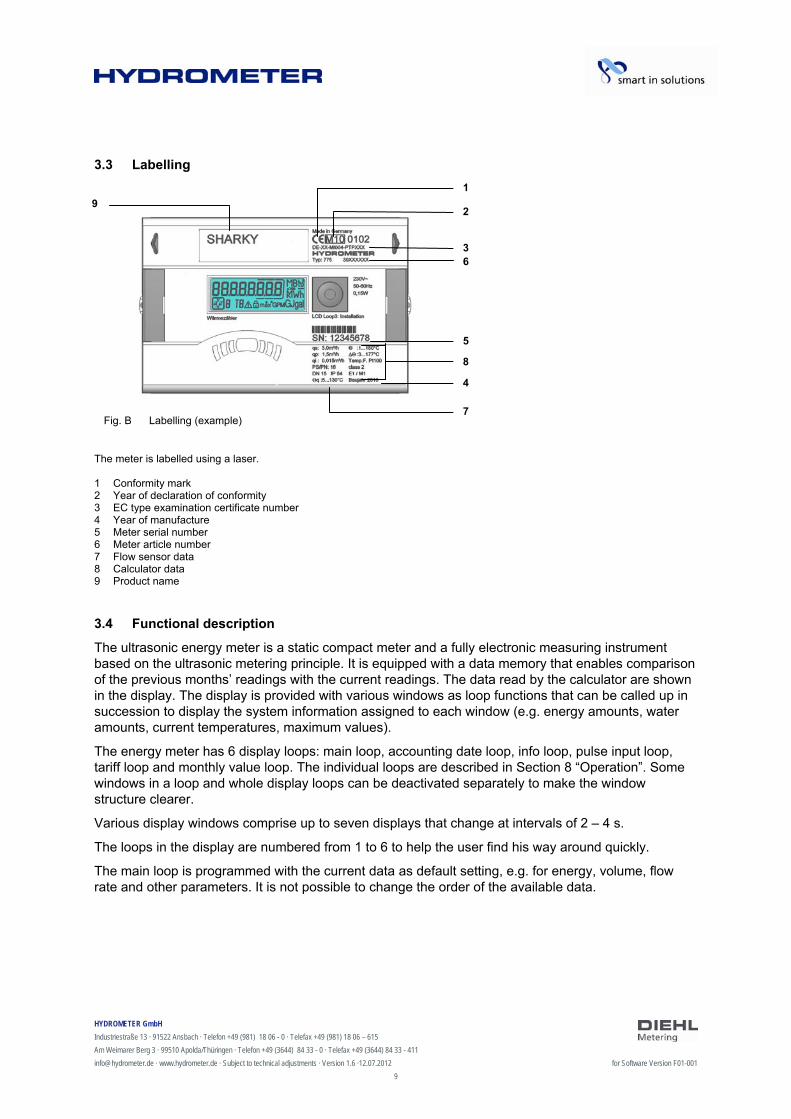
3.3 Labelling
The meter is labelled using a laser. 1 Conformity mark 2 Year of declaration of conformity 3 EC type examination certificate number 4 Year of manufacture 5 Meter serial number 6 Meter article number 7 Flow sensor data 8 Calculator data 9 Product name
3.4 Functional description
The ultrasonic energy meter is a static compact meter and a fully electronic measuring instrument based on the ultrasonic metering principle. It is equipped with a data memory that enables comparison of the previous months’ readings with the current readings. The data read by the calculator are shown in the display. The display is provided with various windows as loop functions that can be called up in succession to display the system information assigned to each window (e.g. energy amounts, water amounts, current temperatures, maximum values).
The energy meter has 6 display loops: main loop, accounting date loop, info loop, pulse input loop, tariff loop and monthly value loop. The individual loops are described in Section 8 “Operation”. Some windows in a loop and whole display loops can be deactivated separately to make the window structure clearer.
Various display windows comprise up to seven displays that change at intervals of 2 – 4 s.
The loops in the display are numbered from 1 to 6 to help the user find his way around quickly.
The main loop is programmed with the current data as default setting, e.g. for energy, volume, flow rate and other parameters. It is not possible to change the order of the available data.
Fig. B Labelling (example)
3
1
2
5
8
4
7
6
9

HYDROMETER GmbH
Industriestraße 13 · 91522 Ansbach · Telefon +49 (981) 18 06 - 0 · Telefax +49 (981) 18 06 – 615
Am Weimarer Berg 3 · 99510 Apolda/Thüringen · Telefon +49 (3644) 84 33 - 0 · Telefax +49 (3644) 84 33 - 411
[email protected] · www.hydrometer.de · Subject to technical adjustments · Version 1.6 ·12.07.2012 for Software Version F01-001
10
3.5 Power supply
Possible power supplies:
A cell, 3.6 V DC lithium battery, with a lifetime of 11 years (standard version, with radio) D cell, 3.6 V DC lithium battery, with a lifetime of 16 years Mains unit 24 V AC Mains unit 230 V AC
Fig. C. Power supplies
1 A or D cell, 3.6 V DC lithium battery 2 Mains unit 24 V AC / 230 V AC The various power supplies can be changed in the field.
NOTE
The meter switches automatically to power save mode if the button is not pressed for approx. 4 minutes. The display is also switched off in this case, but can be switched on again by pressing the button. Communication is maintained, e.g. over the M-Bus or the optical interface. The meter does not switch to power save mode if an error exists. The error is shown in the display as an error code.
Never connect between two phases if a mains unit is used, as this would destroy the mains unit. The protective safety cover must be installed at all times. The cable is to be fused at max. 6 A and protected against manipulation.
Used batteries must be disposed of at suitable collection points.
1 2
HYDROMETER GmbH
Industriestraße 13 · 91522 Ansbach · Telefon +49 (981) 18 06 - 0 · Telefax +49 (981) 18 06 – 615
Am Weimarer Berg 3 · 99510 Apolda/Thüringen · Telefon +49 (3644) 84 33 - 0 · Telefax +49 (3644) 84 33 - 411
[email protected] · www.hydrometer.de · Subject to technical adjustments · Version 1.6 ·12.07.2012 for Software Version F01-001
11
3.5.1 Battery
A 3.6 V DC lithium battery is fitted in the standard version. The battery is not to be charged or short-circuited. Ambient temperatures below 40 °C extend the life of the battery.
DANGER
There is a risk of explosion if the battery is replaced with the wrong type of battery.
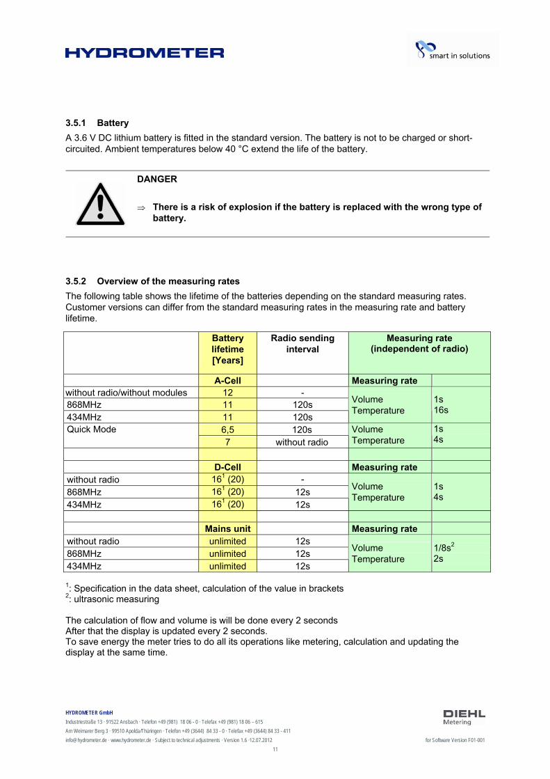
3.5.2 Overview of the measuring rates
The following table shows the lifetime of the batteries depending on the standard measuring rates. Customer versions can differ from the standard measuring rates in the measuring rate and battery lifetime.
1: Specification in the data sheet, calculation of the value in brackets 2: ultrasonic measuring The calculation of flow and volume is will be done every 2 seconds After that the display is updated every 2 seconds. To save energy the meter tries to do all its operations like metering, calculation and updating the display at the same time.
Battery lifetime [Years]
Radio sending interval
Measuring rate (independent of radio)
A-Cell Measuring rate
without radio/without modules 12 - 868MHz 11 120s 434MHz 11 120s
Volume Temperature
1s 16s
6,5 120s Quick Mode
7 without radio
Volume Temperature
1s 4s
D-Cell Measuring rate
without radio 161 (20) -
868MHz 161 (20) 12s 434MHz 161 (20) 12s
Volume Temperature
1s 4s
Mains unit Measuring rate
without radio unlimited 12s 868MHz unlimited 12s 434MHz unlimited 12s
Volume Temperature
1/8s2 2s

HYDROMETER GmbH
Industriestraße 13 · 91522 Ansbach · Telefon +49 (981) 18 06 - 0 · Telefax +49 (981) 18 06 – 615
Am Weimarer Berg 3 · 99510 Apolda/Thüringen · Telefon +49 (3644) 84 33 - 0 · Telefax +49 (3644) 84 33 - 411
[email protected] · www.hydrometer.de · Subject to technical adjustments · Version 1.6 ·12.07.2012 for Software Version F01-001
12
3.5.3 Mains unit
The mains unit indicates to the meter if mains voltage is present. If the mains unit fails, the back-up battery (CR2032) in the mains unit provides the power supply for up to 1 year. This back-up battery can be replaced if necessary. The LCD readings (on pressing button) and the date and time are still updated, but none of the measuring functions work, incl. the flow rate measurement. Communication still functions over the optional M-Bus, RS485 and RS232 modules or the optical interface, but this reduces the life of the back-up battery. The integrated radio function is switched off in the event of mains failure.
3.6 Calculator interfaces
The meter is equipped as standard with a ZVEI optical interface. This is located on the calculator below the display (Fig. D). This interface can be used for communication with the meter (using the IZAR@SET software) and for checking the meter.
Communication uses the M-Bus protocol, for which the Bluetooth IZAR OH BT opto head is suitable.
Fig. D Front of calculator
1 Optical ZVEI interface
1
HYDROMETER GmbH
Industriestraße 13 · 91522 Ansbach · Telefon +49 (981) 18 06 - 0 · Telefax +49 (981) 18 06 – 615
Am Weimarer Berg 3 · 99510 Apolda/Thüringen · Telefon +49 (3644) 84 33 - 0 · Telefax +49 (3644) 84 33 - 411
[email protected] · www.hydrometer.de · Subject to technical adjustments · Version 1.6 ·12.07.2012 for Software Version F01-001
13
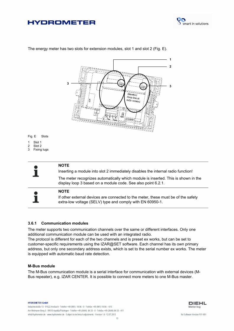
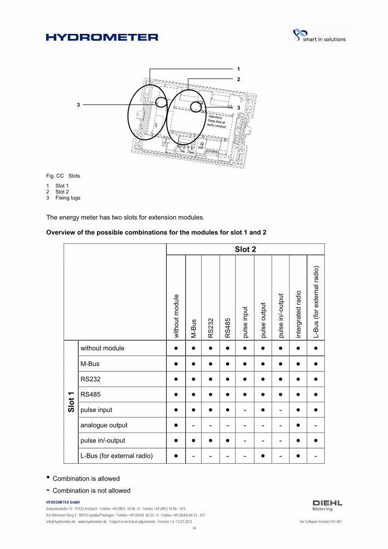
The energy meter has two slots for extension modules, slot 1 and slot 2 (Fig. E).
Fig. E Slots
1 Slot 1 2 Slot 2 3 Fixing lugs
NOTE
Inserting a module into slot 2 immediately disables the internal radio function!
The meter recognizes automatically which module is inserted. This is shown in the display loop 3 based on a module code. See also point 6.2.1.
NOTE
If other external devices are connected to the meter, these must be of the safety extra-low voltage (SELV) type and comply with EN 60950-1.
3.6.1 Communication modules
The meter supports two communication channels over the same or different interfaces. Only one additional communication module can be used with an integrated radio. The protocol is different for each of the two channels and is preset ex works, but can be set to customer-specific requirements using the IZAR@SET software. Each channel has its own primary address, but only one secondary address exists, which is set to the serial number ex works. The meter is equipped with automatic baud rate detection.
M-Bus module
The M-Bus communication module is a serial interface for communication with external devices (M-Bus repeater), e.g. IZAR CENTER. It is possible to connect more meters to one M-Bus master.
2
1
3 3

HYDROMETER GmbH
Industriestraße 13 · 91522 Ansbach · Telefon +49 (981) 18 06 - 0 · Telefax +49 (981) 18 06 – 615
Am Weimarer Berg 3 · 99510 Apolda/Thüringen · Telefon +49 (3644) 84 33 - 0 · Telefax +49 (3644) 84 33 - 411
[email protected] · www.hydrometer.de · Subject to technical adjustments · Version 1.6 ·12.07.2012 for Software Version F01-001
14
Communication via radio
The integrated radio function is an interface for communication of predefined protocols with Hydrometer radio receivers. The communication protocol is preset, but can be defined to a customer-specific protocol using the IZAR@SET software. By default, the internal radio is disabled. When the meter detects a flow, the integrated radio is enabled. If the meter detects a flow without an interruption at least 3 hours, the radio stays on, otherwise it is switched off again.
RS-232 module
The RS-232 communication module is a serial interface for communication with external devices, e.g. a PC. The transmission speed is 300 or 2400 baud. A special data cable is required for connecting this module to the PC. (Order no.: 087H0121)
RS-485 module
The RS-485 communication module is a serial interface for communication with external devices, e.g. a PC. It can only communicate at a transmission speed of 2400 baud.
L-Bus module
The L-Bus communication module is a serial interface for communication with an external radio module, in which the M-Bus protocol is transmitted. It can be used for example if the radio range of the internal radio is not enough.
3.6.2 Function modules
Pulse output module
This module contains connections for two pulse outputs, which can be programmed as desired using the IZAR@SET software. The energy pulse output is marked as standard as “01 - ” on the module and “Out1” in the display. The volume output is marked as “02 - ” on the module and “Out2” in the display.
Pulse input module
This module has 2 pulse inputs for connecting 2 additional pulse meters, such as water meters, gas meters or electricity meters. The possibility of programming the pulse value using the IZAR@SET software enables volume or energy values to be displayed and transmitted remotely over a suitable communication module. Initial meter counts can also be parametrized for these two pulse inputs.
Module IN-OUT
The Module IN-OUT is equipped with two pulse inputs and a pulse output, which can be programmed as desired using the IZAR@SET software. Pulse input 1 is marked “I1 - ” on the module and “IN1” in the display, pulse input 2 “I2 - ” on the module and “IN2” in the display. The pulse output is marked “01 - ” on the module and “Out1” in the display. The pulse output on this module is not galvanic isolated.
Analogue module
The analogue module has the size of 2 standard modules and has two 4-20 mA outputs. If an analogue module is mounted in the meter, no other module can be installed. The internal radio is still working. The connection cable between the main pcb board and the module has to be installed on port 1 (left slot). By default, the two analogue outputs are not programmed, the values can be programmed with the IZAR@SET software (standard version).
HYDROMETER GmbH
Industriestraße 13 · 91522 Ansbach · Telefon +49 (981) 18 06 - 0 · Telefax +49 (981) 18 06 – 615
Am Weimarer Berg 3 · 99510 Apolda/Thüringen · Telefon +49 (3644) 84 33 - 0 · Telefax +49 (3644) 84 33 - 411
[email protected] · www.hydrometer.de · Subject to technical adjustments · Version 1.6 ·12.07.2012 for Software Version F01-001
15
4 Technical data
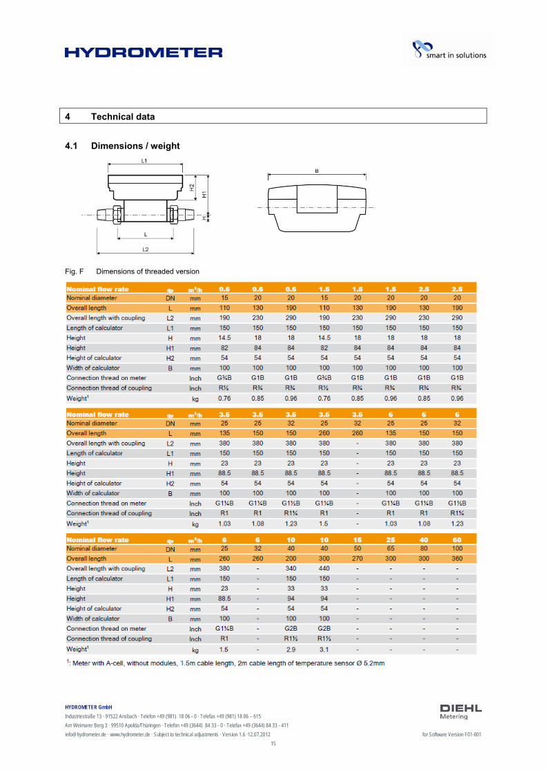
4.1 Dimensions / weight
Fig. F Dimensions of threaded version

HYDROMETER GmbH
Industriestraße 13 · 91522 Ansbach · Telefon +49 (981) 18 06 - 0 · Telefax +49 (981) 18 06 – 615
Am Weimarer Berg 3 · 99510 Apolda/Thüringen · Telefon +49 (3644) 84 33 - 0 · Telefax +49 (3644) 84 33 - 411
[email protected] · www.hydrometer.de · Subject to technical adjustments · Version 1.6 ·12.07.2012 for Software Version F01-001
16
Fig. G Dimensions of flange version
1: Values for PN16 housing 2: Meter with A-cell, without modules, 1.5m cable length, 2m cable length of temperature sensor Ø 5.2mm
HYDROMETER GmbH
Industriestraße 13 · 91522 Ansbach · Telefon +49 (981) 18 06 - 0 · Telefax +49 (981) 18 06 – 615
Am Weimarer Berg 3 · 99510 Apolda/Thüringen · Telefon +49 (3644) 84 33 - 0 · Telefax +49 (3644) 84 33 - 411
[email protected] · www.hydrometer.de · Subject to technical adjustments · Version 1.6 ·12.07.2012 for Software Version F01-001
17
4.2 General data
Nominal size qp: 0.6 – 60 m3/h Ambient temperature: 5 … 55 °C Medium temperature: 5 … 130 °C (150 °C), depending on variant and nominal size
4.3 Power supply
External power supply
230 V AC module / 24 V AC module (Fig. C, item 2, page 10)
Terminals suitable for wires up to 2.5 mm² Electrical isolation Frequency 50 Hz Power consumption 0.12 VA ±10 % Soldered fuse (50mA) The cable is to be fused at max. 6A and protected against manipulation.
4.4 Calculator interfaces
4.4.1 Communication modules
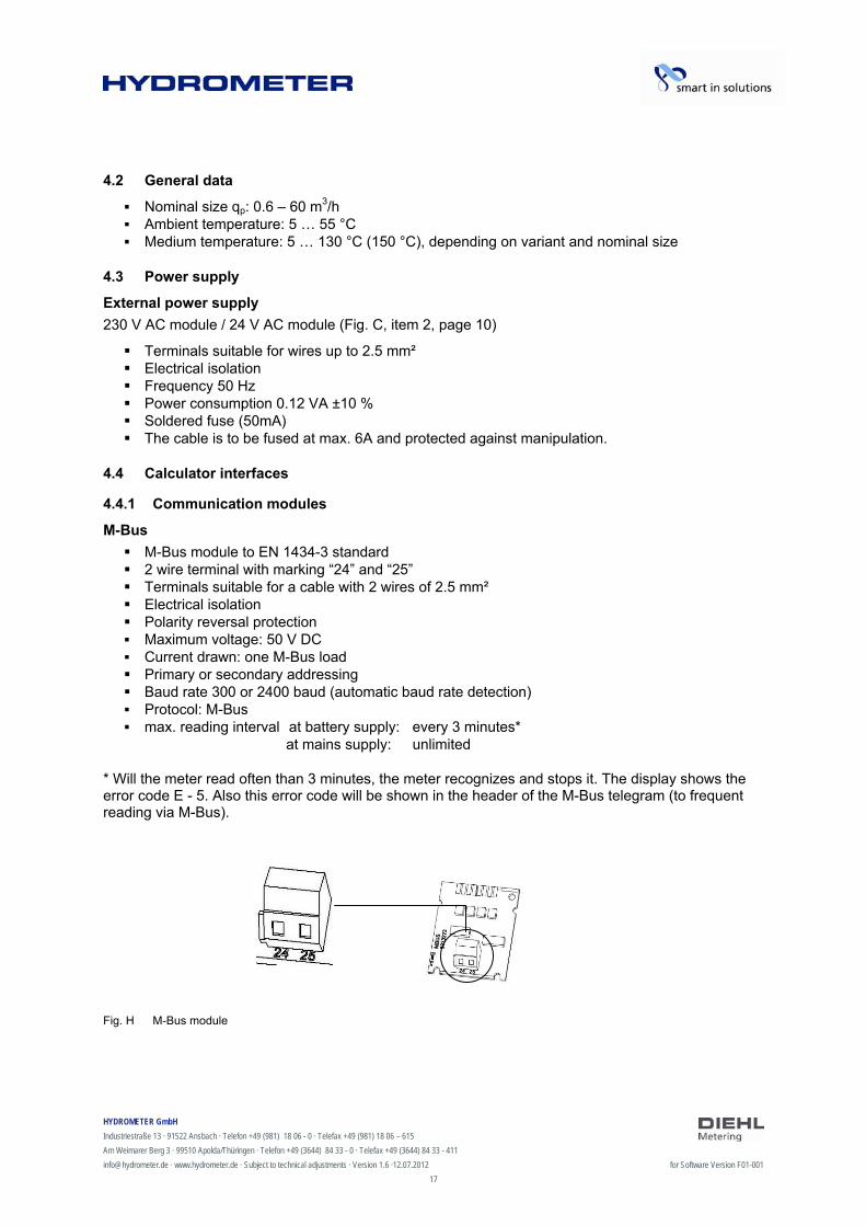
M-Bus
M-Bus module to EN 1434-3 standard 2 wire terminal with marking “24” and “25” Terminals suitable for a cable with 2 wires of 2.5 mm² Electrical isolation Polarity reversal protection Maximum voltage: 50 V DC Current drawn: one M-Bus load Primary or secondary addressing Baud rate 300 or 2400 baud (automatic baud rate detection) Protocol: M-Bus max. reading interval at battery supply: every 3 minutes*
at mains supply: unlimited
* Will the meter read often than 3 minutes, the meter recognizes and stops it. The display shows the error code E - 5. Also this error code will be shown in the header of the M-Bus telegram (to frequent reading via M-Bus).
Fig. H M-Bus module
HYDROMETER GmbH
Industriestraße 13 · 91522 Ansbach · Telefon +49 (981) 18 06 - 0 · Telefax +49 (981) 18 06 – 615
Am Weimarer Berg 3 · 99510 Apolda/Thüringen · Telefon +49 (3644) 84 33 - 0 · Telefax +49 (3644) 84 33 - 411
[email protected] · www.hydrometer.de · Subject to technical adjustments · Version 1.6 ·12.07.2012 for Software Version F01-001
18
Communication via integrated radio
The integrated radio communication has the following specification:
Unidirectional transmission The module sends every 8 ... 256 s (variable, depending on protocol length) typical radio transmitting power 10 dBm ≙ 10 mW Data actuality: online – no time delay between recording readings and data transfer The integrated radio module always accesses the current meter counts Transmission frequency: 868 MHz or 434 MHz Various Hydrometer receivers are available for receiving the protocol (e.g. Bluetooth, GPRS,
LAN, …) Encrypted protocol: Real Data Radio or Open Metering Reading modes: Walk-By, Drive-By, Fixed Network For problematic radio installations (shielding) and to short dstance to the radio receiver also the
module set external radio can be used.
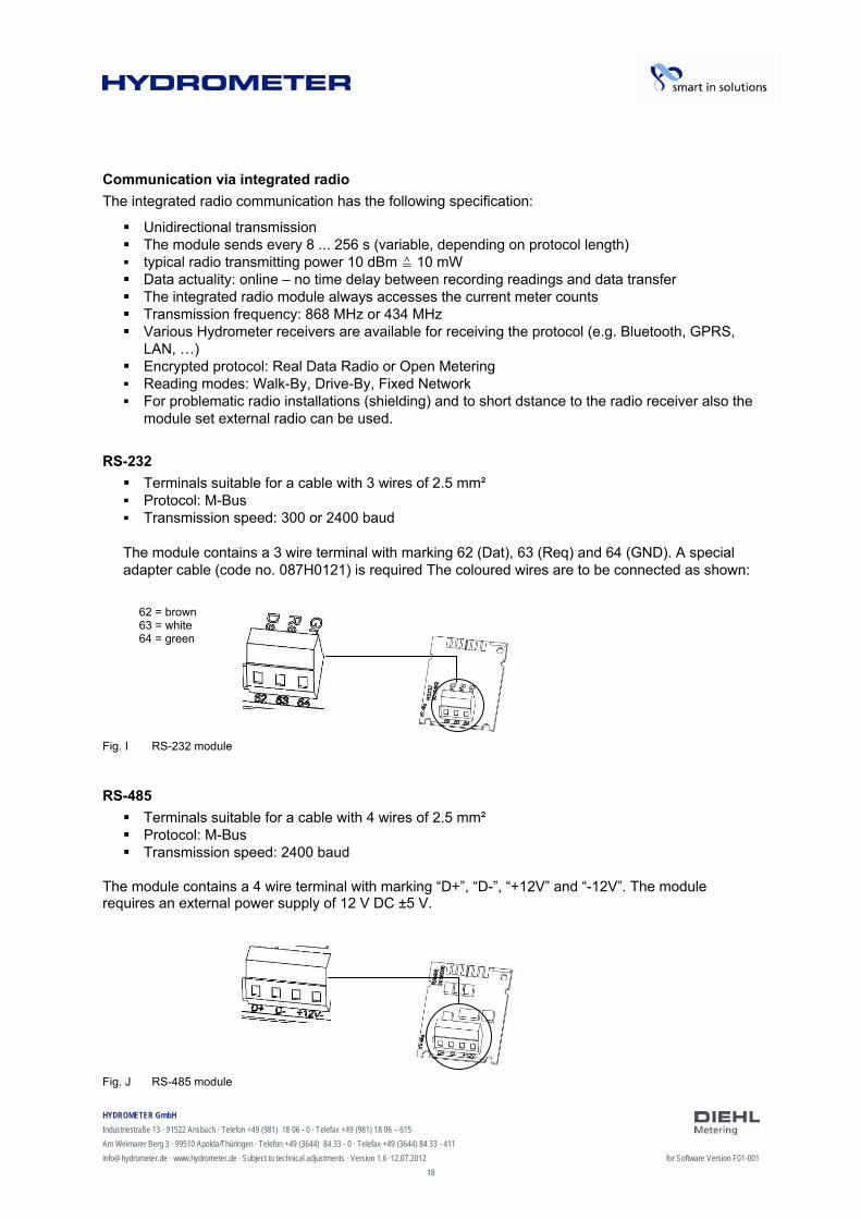
RS-232
Terminals suitable for a cable with 3 wires of 2.5 mm² Protocol: M-Bus Transmission speed: 300 or 2400 baud The module contains a 3 wire terminal with marking 62 (Dat), 63 (Req) and 64 (GND). A special adapter cable (code no. 087H0121) is required The coloured wires are to be connected as shown:
Fig. I RS-232 module
RS-485
Terminals suitable for a cable with 4 wires of 2.5 mm² Protocol: M-Bus Transmission speed: 2400 baud
The module contains a 4 wire terminal with marking “D+”, “D-”, “+12V” and “-12V”. The module requires an external power supply of 12 V DC ±5 V.
Fig. J RS-485 module
62 = brown 63 = white 64 = green
HYDROMETER GmbH
Industriestraße 13 · 91522 Ansbach · Telefon +49 (981) 18 06 - 0 · Telefax +49 (981) 18 06 – 615
Am Weimarer Berg 3 · 99510 Apolda/Thüringen · Telefon +49 (3644) 84 33 - 0 · Telefax +49 (3644) 84 33 - 411
[email protected] · www.hydrometer.de · Subject to technical adjustments · Version 1.6 ·12.07.2012 for Software Version F01-001
19
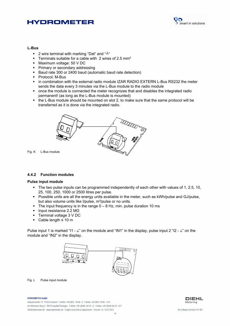
L-Bus
2 wire terminal with marking “Dat“ and ““ Terminals suitable for a cable with 2 wires of 2.5 mm² Maximum voltage: 50 V DC Primary or secondary addressing Baud rate 300 or 2400 baud (automatic baud rate detection) Protocol: M-Bus in combination with the external radio module IZAR RADIO EXTERN L-Bus RS232 the meter
sends the data every 3 minutes via the L-Bus module to the radio module once the module is connected the meter recognizes that and disables the integrated radio
permanent! (as long as the L-Bus module is mounted) the L-Bus module should be mounted on slot 2, to make sure that the same protocol will be
transferred as it is done via the integrated radio.
Fig. K L-Bus module
4.4.2 Function modules
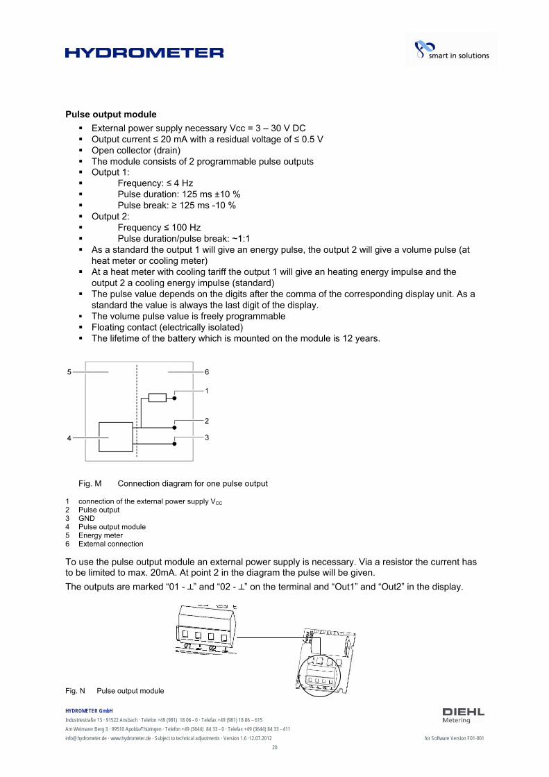
Pulse input module
The two pulse inputs can be programmed independently of each other with values of 1, 2.5, 10, 25, 100, 250, 1000 or 2500 litres per pulse.
Possible units are all the energy units available in the meter, such as kWh/pulse and GJ/pulse, but also volume units like l/pulse, m³/pulse or no units.
The input frequency is in the range 0 – 8 Hz, min. pulse duration 10 ms Input resistance 2.2 MΩ Terminal voltage 3 V DC Cable length ≤ 10 m
Pulse input 1 is marked “I1 - ” on the module and “IN1” in the display, pulse input 2 “I2 - ” on the module and “IN2” in the display.
Fig. L Pulse input module
HYDROMETER GmbH
Industriestraße 13 · 91522 Ansbach · Telefon +49 (981) 18 06 - 0 · Telefax +49 (981) 18 06 – 615
Am Weimarer Berg 3 · 99510 Apolda/Thüringen · Telefon +49 (3644) 84 33 - 0 · Telefax +49 (3644) 84 33 - 411
[email protected] · www.hydrometer.de · Subject to technical adjustments · Version 1.6 ·12.07.2012 for Software Version F01-001
20
Pulse output module
External power supply necessary Vcc = 3 – 30 V DC Output current ≤ 20 mA with a residual voltage of ≤ 0.5 V Open collector (drain) The module consists of 2 programmable pulse outputs Output 1: Frequency: ≤ 4 Hz Pulse duration: 125 ms ±10 % Pulse break: ≥ 125 ms -10 % Output 2: Frequency ≤ 100 Hz Pulse duration/pulse break: ~1:1 As a standard the output 1 will give an energy pulse, the output 2 will give a volume pulse (at
heat meter or cooling meter) At a heat meter with cooling tariff the output 1 will give an heating energy impulse and the
output 2 a cooling energy impulse (standard) The pulse value depends on the digits after the comma of the corresponding display unit. As a
standard the value is always the last digit of the display. The volume pulse value is freely programmable Floating contact (electrically isolated) The lifetime of the battery which is mounted on the module is 12 years.
Fig. M Connection diagram for one pulse output
1 connection of the external power supply VCC 2 Pulse output 3 GND 4 Pulse output module 5 Energy meter 6 External connection To use the pulse output module an external power supply is necessary. Via a resistor the current has to be limited to max. 20mA. At point 2 in the diagram the pulse will be given.
The outputs are marked “01 - ” and “02 - ” on the terminal and “Out1” and “Out2” in the display.
Fig. N Pulse output module
HYDROMETER GmbH
Industriestraße 13 · 91522 Ansbach · Telefon +49 (981) 18 06 - 0 · Telefax +49 (981) 18 06 – 615
Am Weimarer Berg 3 · 99510 Apolda/Thüringen · Telefon +49 (3644) 84 33 - 0 · Telefax +49 (3644) 84 33 - 411
[email protected] · www.hydrometer.de · Subject to technical adjustments · Version 1.6 ·12.07.2012 for Software Version F01-001
21
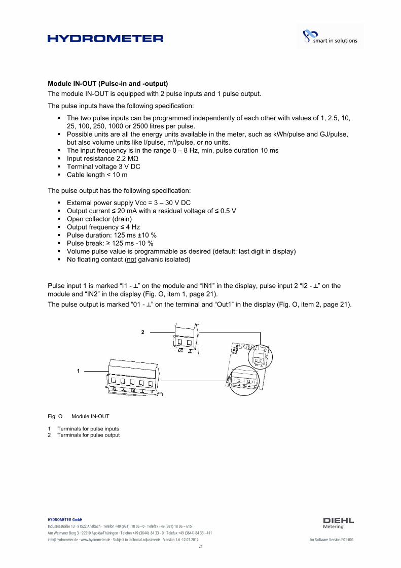
Module IN-OUT (Pulse-in and -output)
The module IN-OUT is equipped with 2 pulse inputs and 1 pulse output.
The pulse inputs have the following specification:
The two pulse inputs can be programmed independently of each other with values of 1, 2.5, 10, 25, 100, 250, 1000 or 2500 litres per pulse.
Possible units are all the energy units available in the meter, such as kWh/pulse and GJ/pulse, but also volume units like l/pulse, m³/pulse, or no units.
The input frequency is in the range 0 – 8 Hz, min. pulse duration 10 ms Input resistance 2.2 MΩ Terminal voltage 3 V DC Cable length < 10 m
The pulse output has the following specification:
External power supply Vcc = 3 – 30 V DC Output current ≤ 20 mA with a residual voltage of ≤ 0.5 V Open collector (drain) Output frequency ≤ 4 Hz Pulse duration: 125 ms ±10 % Pulse break: ≥ 125 ms -10 % Volume pulse value is programmable as desired (default: last digit in display) No floating contact (not galvanic isolated)
Pulse input 1 is marked “I1 - ” on the module and “IN1” in the display, pulse input 2 “I2 - ” on the module and “IN2” in the display (Fig. O, item 1, page 21).
The pulse output is marked “01 - ” on the terminal and “Out1” in the display (Fig. O, item 2, page 21).
Fig. O Module IN-OUT 1 Terminals for pulse inputs 2 Terminals for pulse output
1
2

HYDROMETER GmbH
Industriestraße 13 · 91522 Ansbach · Telefon +49 (981) 18 06 - 0 · Telefax +49 (981) 18 06 – 615
Am Weimarer Berg 3 · 99510 Apolda/Thüringen · Telefon +49 (3644) 84 33 - 0 · Telefax +49 (3644) 84 33 - 411
[email protected] · www.hydrometer.de · Subject to technical adjustments · Version 1.6 ·12.07.2012 for Software Version F01-001
22
Analogue output module
2 passive outputs External power supply: 10 … 30 V DC Current loop 4 … 20 mA
where 4 mA = 0 value; 20 mA = programmed max. value Overload up to 20.5 mA, then fault current Errors are generated at 3.5 mA or 22.6 mA (programmable) Output values: power, flow rate, forward temperature, return temperature, difference
temperature Maximal cable length 10 m (acc. to EN 1434)
To use the analogue output module an external power supply is necessary. The outputs are marked “1” and “2” on the terminal with the respective polarity “+” and “-”. Fig. P Analogue module Connection diagram
+ 1 -
Analogue output
10 … 30V DC
HYDROMETER GmbH
Industriestraße 13 · 91522 Ansbach · Telefon +49 (981) 18 06 - 0 · Telefax +49 (981) 18 06 – 615
Am Weimarer Berg 3 · 99510 Apolda/Thüringen · Telefon +49 (3644) 84 33 - 0 · Telefax +49 (3644) 84 33 - 411
[email protected] · www.hydrometer.de · Subject to technical adjustments · Version 1.6 ·12.07.2012 for Software Version F01-001
23
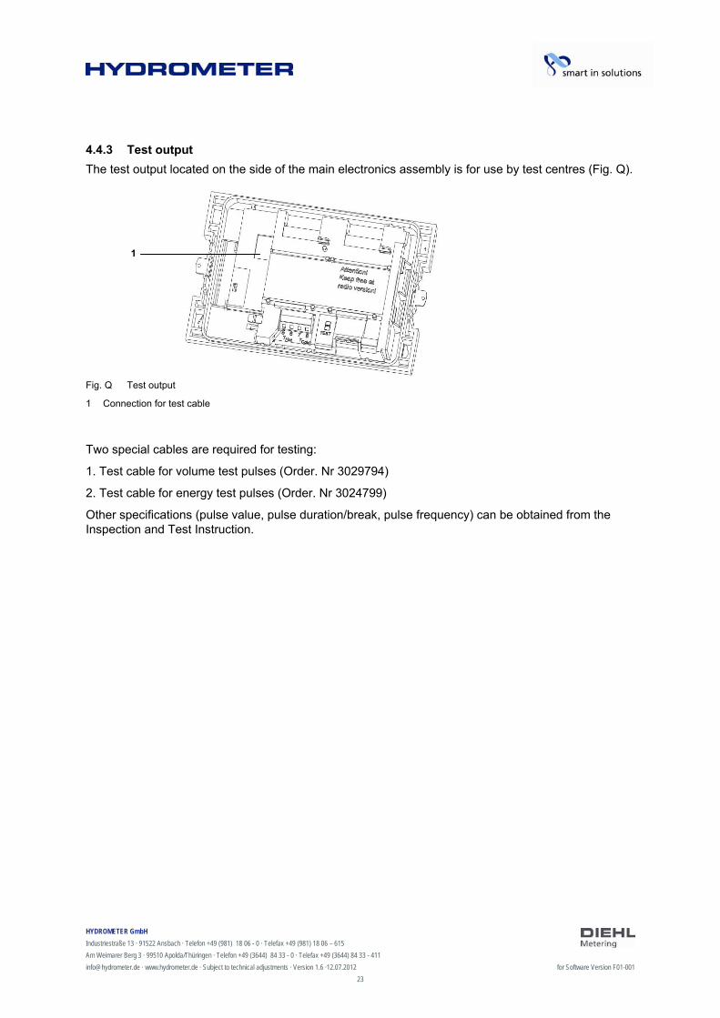
4.4.3 Test output
The test output located on the side of the main electronics assembly is for use by test centres (Fig. Q).
Fig. Q Test output
1 Connection for test cable
Two special cables are required for testing:
1. Test cable for volume test pulses (Order. Nr 3029794)
2. Test cable for energy test pulses (Order. Nr 3024799)
Other specifications (pulse value, pulse duration/break, pulse frequency) can be obtained from the Inspection and Test Instruction.
1
HYDROMETER GmbH
Industriestraße 13 · 91522 Ansbach · Telefon +49 (981) 18 06 - 0 · Telefax +49 (981) 18 06 – 615
Am Weimarer Berg 3 · 99510 Apolda/Thüringen · Telefon +49 (3644) 84 33 - 0 · Telefax +49 (3644) 84 33 - 411
[email protected] · www.hydrometer.de · Subject to technical adjustments · Version 1.6 ·12.07.2012 for Software Version F01-001
24
5 Transport, storage
5.1 Unpacking the energy meter
Heat meters and cooling meters are measuring instruments and must be handled carefully. To protect against damage and soiling, they should not be removed from the packaging until shortly before installation.
5.2 Transporting the energy meter
The meter is only to be transported in its original packaging.
5.3 Storage of energy meter
The meter must be stored in a dry place. Storage temperature -25 °C ... +60 °C Relative ambient humidity < 93 %
HYDROMETER GmbH
Industriestraße 13 · 91522 Ansbach · Telefon +49 (981) 18 06 - 0 · Telefax +49 (981) 18 06 – 615
Am Weimarer Berg 3 · 99510 Apolda/Thüringen · Telefon +49 (3644) 84 33 - 0 · Telefax +49 (3644) 84 33 - 411
[email protected] · www.hydrometer.de · Subject to technical adjustments · Version 1.6 ·12.07.2012 for Software Version F01-001
25
6 Installation
NOTE
This installation guide is intended for trained personnel and does not contain any basic working steps.
The meter may only be installed in dry and frost-free areas in buildings.
Avoid sharp edges (thread, flange, measuring tube). Only install and remove the meter when the system is not under pressure.
Important! The seal on the meter (Fig. R, page 26) must not be damaged! A damaged seal immediately invalidates the factory warranty and the verification or declaration of conformity. The cables supplied with the meter must not be shortened or changed in any other way.
Live parts may be exposed when opening covers or removing parts. Connection points may also be live.
The regulations covering the use of energy meters and electrical installations must be observed!
All instructions listed in the installation guide for the meter must be observed. A cold leakage test by hydraulic pressure is to be carried out after installation.
The specified medium temperature is 5 ... 130 °C (150 °C). The temperature range depends on variant and nominal size. The encapsulated variant is to be used if condensation is expected (cooling and heat meter with cooling tariff).
Only water without additives may be used as medium, according to AGFW leaflet FW510 (Exception: Specifically programmed meter for medium Tyfocor LS). The calculator has to be removed from the flow sensor at a medium temperature above 90 °C or if the water temperature is lower than the ambient temperature.
The IZAR@SET software is used for reading/parametrization and is obtainable on the Internet at http://www.hydrometer.de.
DANGER
Do not touch live parts during installation work.
Risk of serious injuries or death!
The meter installation is only to be performed by an installation and/or electrical contractor.
Personnel must be trained in the installation of medium-voltage electrical equipment (up to 1000 V).
HYDROMETER GmbH
Industriestraße 13 · 91522 Ansbach · Telefon +49 (981) 18 06 - 0 · Telefax +49 (981) 18 06 – 615
Am Weimarer Berg 3 · 99510 Apolda/Thüringen · Telefon +49 (3644) 84 33 - 0 · Telefax +49 (3644) 84 33 - 411
[email protected] · www.hydrometer.de · Subject to technical adjustments · Version 1.6 ·12.07.2012 for Software Version F01-001
26
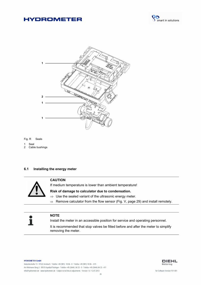
Fig. R Seals
1 Seal 2 Cable bushings
6.1 Installing the energy meter
CAUTION
If medium temperature is lower than ambient temperature!
Risk of damage to calculator due to condensation.
Use the sealed variant of the ultrasonic energy meter.
Remove calculator from the flow sensor (Fig. V, page 29) and install remotely.
NOTE
Install the meter in an accessible position for service and operating personnel.
It is recommended that stop valves be fitted before and after the meter to simplify removing the meter.
1
1
1
2
HYDROMETER GmbH
Industriestraße 13 · 91522 Ansbach · Telefon +49 (981) 18 06 - 0 · Telefax +49 (981) 18 06 – 615
Am Weimarer Berg 3 · 99510 Apolda/Thüringen · Telefon +49 (3644) 84 33 - 0 · Telefax +49 (3644) 84 33 - 411
[email protected] · www.hydrometer.de · Subject to technical adjustments · Version 1.6 ·12.07.2012 for Software Version F01-001
27
The following tasks are necessary for installing the energy meter:
1. Install the flow sensor, see Section 6.1.1
2. Install the calculator, see Section 6.1.2
3. Connect the temperature sensor, see Section 6.1.3
4. Install the temperature sensor, see Section 6.1.4
6.1.1 Installing the flow sensor
NOTE
Thoroughly flush out the system before installing the flow sensor. It is recommended that a strainer be fitted before the flow sensor or at another suitable position in the heating or cooling circuit. The straight calming length of inlet pipe to the flow sensor and the straight calming length of outlet pipe at the output of the meter may be 0 DN, but an inlet pipe length of 10 DN is recommended before the meter for heating systems without temperature mixing or with temperature stratification.
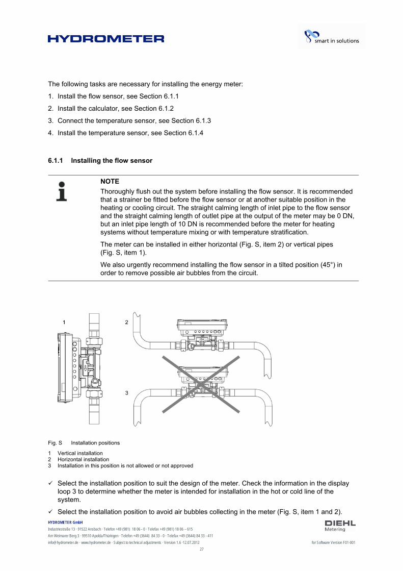
The meter can be installed in either horizontal (Fig. S, item 2) or vertical pipes (Fig. S, item 1).
We also urgently recommend installing the flow sensor in a tilted position (45°) in order to remove possible air bubbles from the circuit.
Fig. S Installation positions
1 Vertical installation 2 Horizontal installation 3 Installation in this position is not allowed or not approved
Select the installation position to suit the design of the meter. Check the information in the display loop 3 to determine whether the meter is intended for installation in the hot or cold line of the system.
Select the installation position to avoid air bubbles collecting in the meter (Fig. S, item 1 and 2).

HYDROMETER GmbH
Industriestraße 13 · 91522 Ansbach · Telefon +49 (981) 18 06 - 0 · Telefax +49 (981) 18 06 – 615
Am Weimarer Berg 3 · 99510 Apolda/Thüringen · Telefon +49 (3644) 84 33 - 0 · Telefax +49 (3644) 84 33 - 411
[email protected] · www.hydrometer.de · Subject to technical adjustments · Version 1.6 ·12.07.2012 for Software Version F01-001
28
1. Install the flow sensor so that the direction of the arrow on the sensor corresponds to the direction of flow (Fig. T, page 28).
Fig. T Direction of flow
1 Arrow indicating direction 2 Direction of flow
2. Ensure that the flow sensor is always filled with water. The meter only measures the energy if the pipes are completely filled, otherwise a corresponding error message is shown in the display.
6.1.2 Installing the calculator
Make sure the calculator is sufficiently far away from possible sources of electromagnetic interference (switches, electric motors, fluorescent lamps, etc.).
Installation at medium temperature < 90 °C or at TWater > TAmbient: Install the calculator on the flow sensor (Fig. U, page 28).
Fig. U Calculator installed on the flow sensor
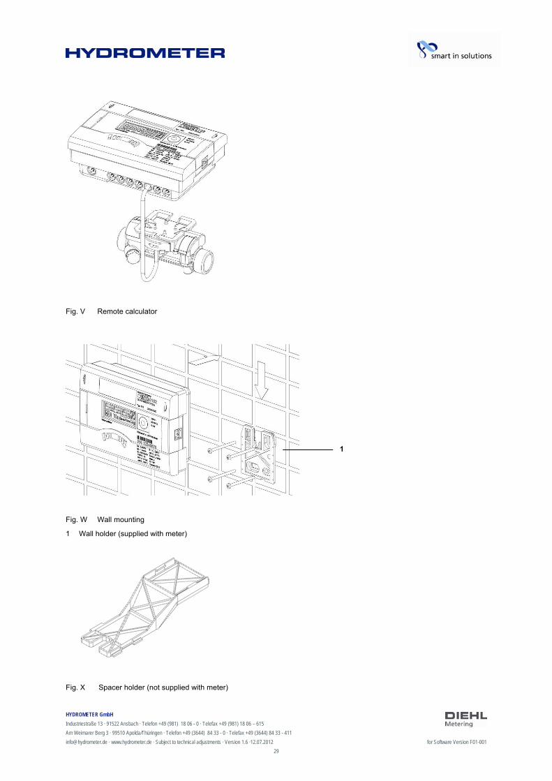
Installation at medium temperature > 90 °C or at TWater < TAmbient (application as cooling meter or heat meter with cooling tariff). Install the calculator remotely at a sufficient distance away from heat sources (Fig. V, page 29), e.g. on the wall (Fig. W, page 29). A wall holder (Fig. W, item 1, page 29, supplied with meter) or a spacer holder (Fig. X, page 29, optional) is available for this purpose.
HYDROMETER GmbH
Industriestraße 13 · 91522 Ansbach · Telefon +49 (981) 18 06 - 0 · Telefax +49 (981) 18 06 – 615
Am Weimarer Berg 3 · 99510 Apolda/Thüringen · Telefon +49 (3644) 84 33 - 0 · Telefax +49 (3644) 84 33 - 411
[email protected] · www.hydrometer.de · Subject to technical adjustments · Version 1.6 ·12.07.2012 for Software Version F01-001
29
Fig. V Remote calculator
Fig. W Wall mounting
1 Wall holder (supplied with meter) Fig. X Spacer holder (not supplied with meter)
1
HYDROMETER GmbH
Industriestraße 13 · 91522 Ansbach · Telefon +49 (981) 18 06 - 0 · Telefax +49 (981) 18 06 – 615
Am Weimarer Berg 3 · 99510 Apolda/Thüringen · Telefon +49 (3644) 84 33 - 0 · Telefax +49 (3644) 84 33 - 411
[email protected] · www.hydrometer.de · Subject to technical adjustments · Version 1.6 ·12.07.2012 for Software Version F01-001
30
6.1.3 Connecting temperature sensor
NOTE
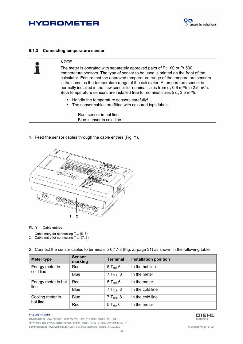
The meter is operated with separately approved pairs of Pt 100 or Pt 500 temperature sensors. The type of sensor to be used is printed on the front of the calculator. Ensure that the approved temperature range of the temperature sensors is the same as the temperature range of the calculator! A temperature sensor is normally installed in the flow sensor for nominal sizes from qp 0.6 m³/h to 2.5 m³/h. Both temperature sensors are installed free for nominal sizes ≥ qp 3.5 m³/h.
Handle the temperature sensors carefully! The sensor cables are fitted with coloured type labels:
- Red: sensor in hot line - Blue: sensor in cold line
1. Feed the sensor cables through the cable entries (Fig. Y).
Fig. Y Cable entries
1 Cable entry for connecting THot (5, 6) 2 Cable entry for connecting TCold (7, 8)
2. Connect the sensor cables to terminals 5-6 / 7-8 (Fig. Z, page 31) as shown in the following table.
Meter type Sensor marking
Terminal Installation position
Red 5 THot 6 In the hot line Energy meter in cold line
Blue 7 TCold 8 In the meter
Red 5 THot 6 In the meter Energy meter in hot line
Blue 7 TCold 8 In the cold line
Blue 7 TCold 8 In the cold line Cooling meter in hot line
Red 5 THot 6 In the meter
1 2
HYDROMETER GmbH
Industriestraße 13 · 91522 Ansbach · Telefon +49 (981) 18 06 - 0 · Telefax +49 (981) 18 06 – 615
Am Weimarer Berg 3 · 99510 Apolda/Thüringen · Telefon +49 (3644) 84 33 - 0 · Telefax +49 (3644) 84 33 - 411
[email protected] · www.hydrometer.de · Subject to technical adjustments · Version 1.6 ·12.07.2012 for Software Version F01-001
31
Blue 7 TCold 8 In the meter Cooling meter in cold line
Red 5 THot 6 In the hot line
Red 5 THot 6 In the hot line Air conditioning meter in cold line
Blue 7 TCold 8 In the meter
Red 5 THot 6 In the meter Air conditioning meter in hot line
Blue 7 TCold 8 In the cold line
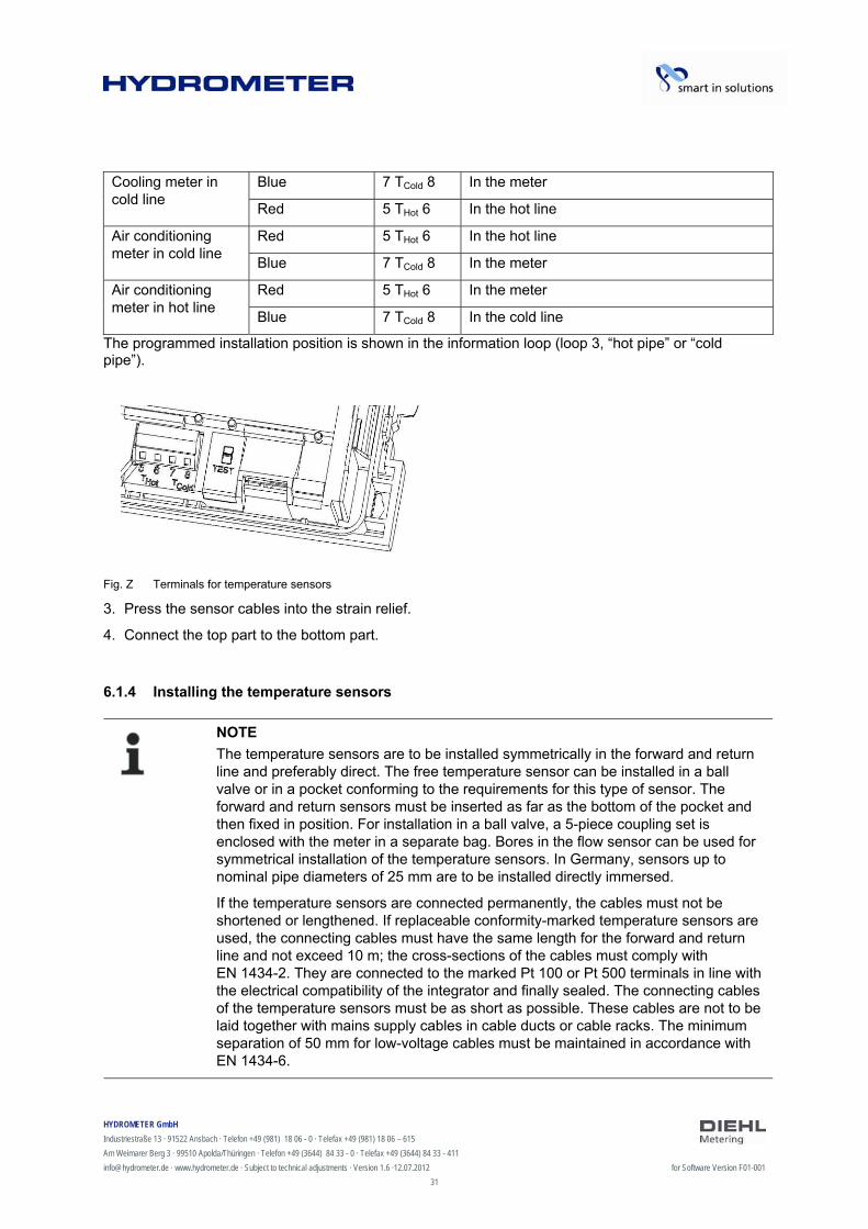
The programmed installation position is shown in the information loop (loop 3, “hot pipe” or “cold pipe”).
Fig. Z Terminals for temperature sensors
3. Press the sensor cables into the strain relief.
4. Connect the top part to the bottom part.
6.1.4 Installing the temperature sensors
NOTE
The temperature sensors are to be installed symmetrically in the forward and return line and preferably direct. The free temperature sensor can be installed in a ball valve or in a pocket conforming to the requirements for this type of sensor. The forward and return sensors must be inserted as far as the bottom of the pocket and then fixed in position. For installation in a ball valve, a 5-piece coupling set is enclosed with the meter in a separate bag. Bores in the flow sensor can be used for symmetrical installation of the temperature sensors. In Germany, sensors up to nominal pipe diameters of 25 mm are to be installed directly immersed.
If the temperature sensors are connected permanently, the cables must not be shortened or lengthened. If replaceable conformity-marked temperature sensors are used, the connecting cables must have the same length for the forward and return line and not exceed 10 m; the cross-sections of the cables must comply with EN 1434-2. They are connected to the marked Pt 100 or Pt 500 terminals in line with the electrical compatibility of the integrator and finally sealed. The connecting cables of the temperature sensors must be as short as possible. These cables are not to be laid together with mains supply cables in cable ducts or cable racks. The minimum separation of 50 mm for low-voltage cables must be maintained in accordance with EN 1434-6.

HYDROMETER GmbH
Industriestraße 13 · 91522 Ansbach · Telefon +49 (981) 18 06 - 0 · Telefax +49 (981) 18 06 – 615
Am Weimarer Berg 3 · 99510 Apolda/Thüringen · Telefon +49 (3644) 84 33 - 0 · Telefax +49 (3644) 84 33 - 411
[email protected] · www.hydrometer.de · Subject to technical adjustments · Version 1.6 ·12.07.2012 for Software Version F01-001
32
Installation possibilities:
Installation in a ball valve with adapter (5-piece coupling set in separate bag) Installation in a pocket
Installation in a ball valve with adapter
Use ball valves suitable for temperature sensor installation with M10 x 1.
1. Close the ball valve.
2. Unscrew the plug screw from the ball valve.
3. Place an O-ring from the enclosed coupling set on the mounting pin (Fig. AA, item 2).
Fig. AA Installing the temperature sensor
4. Insert the O-ring with the mounting pin in the sensor hole of the ball valve using turning movements (Fig. AA, item 3).
5. Position the O-ring in its final position using the other end of the mounting pin (Fig. AA, item 4).
6. Push the fixing screw onto the temperature sensor.
7. Place the mounting pin with the sleeve end over the temperature sensor as far as it will go.
8. The temperature sensor is held in the fixing screw.
9. Press in the slotted pin on the temperature sensor coupling using a pair of pliers (Fig. AA, item 6).
10. Remove the mounting pin from the temperature sensor (Fig. AA, item 5).
11. Now insert the temperature sensor with the adapter coupling into the ball valve and tighten the brass or plastic screw by hand (2-3 Nm) (Fig. AA, item 7).
HYDROMETER GmbH
Industriestraße 13 · 91522 Ansbach · Telefon +49 (981) 18 06 - 0 · Telefax +49 (981) 18 06 – 615
Am Weimarer Berg 3 · 99510 Apolda/Thüringen · Telefon +49 (3644) 84 33 - 0 · Telefax +49 (3644) 84 33 - 411
[email protected] · www.hydrometer.de · Subject to technical adjustments · Version 1.6 ·12.07.2012 for Software Version F01-001
33
Installation in a pocket
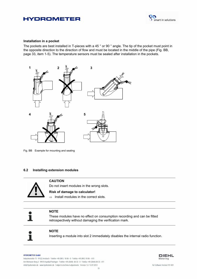
The pockets are best installed in T-pieces with a 45 ° or 90 ° angle. The tip of the pocket must point in the opposite direction to the direction of flow and must be located in the middle of the pipe (Fig. BB, page 33, item 1-5). The temperature sensors must be sealed after installation in the pockets.
Fig. BB Example for mounting and sealing
6.2 Installing extension modules
CAUTION
Do not insert modules in the wrong slots.
Risk of damage to calculator!
Install modules in the correct slots.
NOTE
These modules have no effect on consumption recording and can be fitted retrospectively without damaging the verification mark.
NOTE
Inserting a module into slot 2 immediately disables the internal radio function.
HYDROMETER GmbH
Industriestraße 13 · 91522 Ansbach · Telefon +49 (981) 18 06 - 0 · Telefax +49 (981) 18 06 – 615
Am Weimarer Berg 3 · 99510 Apolda/Thüringen · Telefon +49 (3644) 84 33 - 0 · Telefax +49 (3644) 84 33 - 411
[email protected] · www.hydrometer.de · Subject to technical adjustments · Version 1.6 ·12.07.2012 for Software Version F01-001
34
Fig. CC Slots
1 Slot 1 2 Slot 2 3 Fixing lugs The energy meter has two slots for extension modules. Overview of the possible combinations for the modules for slot 1 and 2
Slot 2
with
out m
odul
e
M-B
us
RS
232
RS
485
pul
se in
put
pul
se o
utpu
t
pul
se in
/-ou
tput
inte
rgra
ted
radi
o
L-B
us (
for
exte
rnal
rad
io)
without module • • • • • • • • • M-Bus • • • • • • • • • RS232 • • • • • • • • • RS485 • • • • • • • • • pulse input • • • • - • - • • analogue output • - - - - - - • -
pulse in/-output • • • • - - - • •
Slo
t 1
L-Bus (for external radio) • - - - - • - • -
• Combination is allowed
- Combination is not allowed
2
1
33
HYDROMETER GmbH
Industriestraße 13 · 91522 Ansbach · Telefon +49 (981) 18 06 - 0 · Telefax +49 (981) 18 06 – 615
Am Weimarer Berg 3 · 99510 Apolda/Thüringen · Telefon +49 (3644) 84 33 - 0 · Telefax +49 (3644) 84 33 - 411
[email protected] · www.hydrometer.de · Subject to technical adjustments · Version 1.6 ·12.07.2012 for Software Version F01-001
35
The modules can be used and combined as shown in the above table. The analogue module occupies both slots. These modules have no effect on consumption recording and can be fitted retrospectively without damaging the verification mark.
WARNING
Electrostatic discharge.
Risk of damage to meter and particularly electronic components, for which no liability is accepted!
Observe the relevant ESD (electrostatic discharge) regulations. No liability is accepted for damage (especially to electronic components) resulting from failure to comply with the ESD regulations.
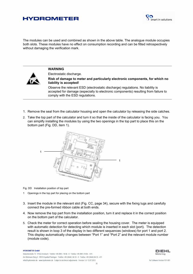
1. Remove the seal from the calculator housing and open the calculator by releasing the side catches.
2. Take the top part of the calculator and turn it so that the inside of the calculator is facing you. You can simplify installing the modules by using the two openings in the top part to place this on the bottom part (Fig. DD, item 1).
Fig. DD Installation position of top part
1 Openings in the top part for placing on the bottom part 3. Insert the module in the relevant slot (Fig. CC, page 34), secure with the fixing lugs and carefully
connect the pre-formed ribbon cable at both ends.
4. Now remove the top part from the installation position, turn it and replace it in the correct position on the bottom part of the calculator.
5. Check the meter for correct operation before sealing the housing cover. The meter is equipped with automatic detection for detecting which module is inserted in each slot (port). The detection result is shown in loop 3 of the display in two different sequences (windows) for port 1 and port 2. This display automatically changes between “Port 1” and “Port 2” and the relevant module number (module code).
1
1
HYDROMETER GmbH
Industriestraße 13 · 91522 Ansbach · Telefon +49 (981) 18 06 - 0 · Telefax +49 (981) 18 06 – 615
Am Weimarer Berg 3 · 99510 Apolda/Thüringen · Telefon +49 (3644) 84 33 - 0 · Telefax +49 (3644) 84 33 - 411
[email protected] · www.hydrometer.de · Subject to technical adjustments · Version 1.6 ·12.07.2012 for Software Version F01-001
36
automatic alternating display
automatic alternating display
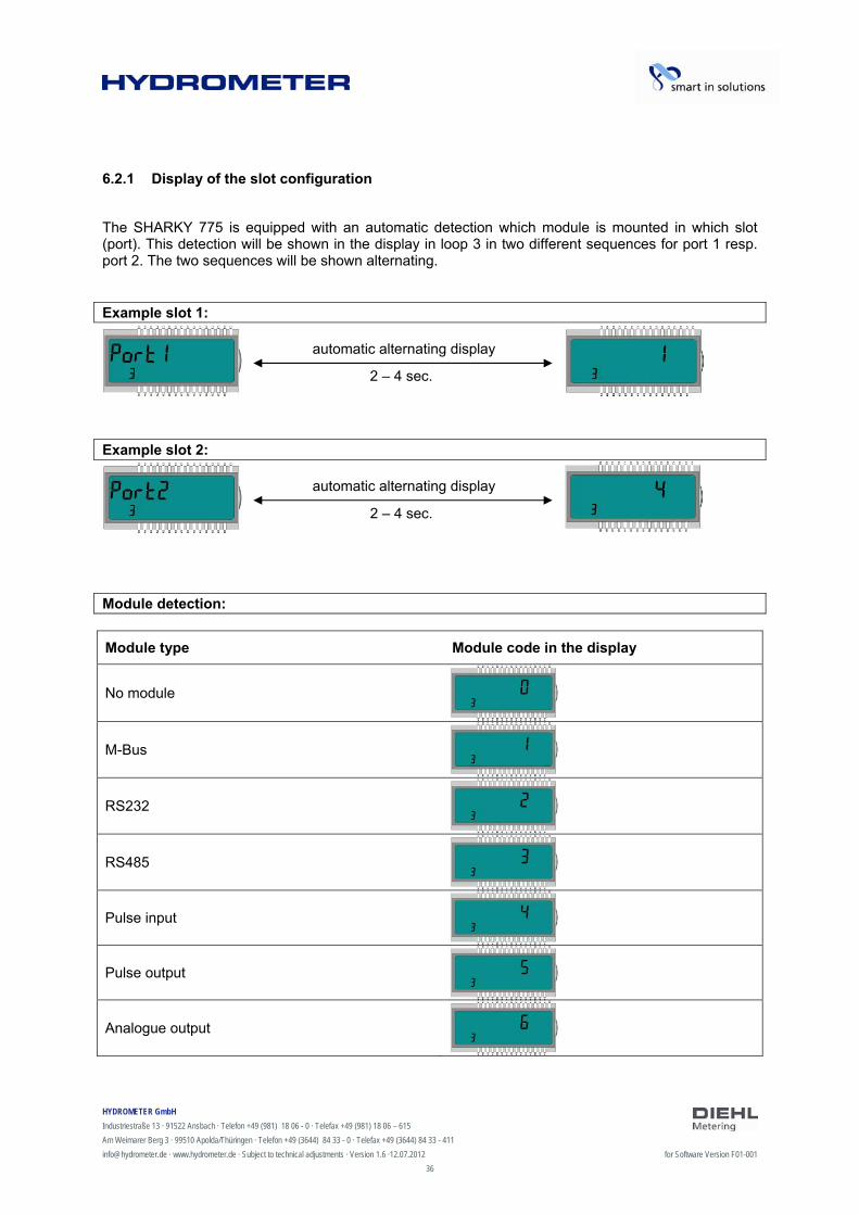
6.2.1 Display of the slot configuration
The SHARKY 775 is equipped with an automatic detection which module is mounted in which slot (port). This detection will be shown in the display in loop 3 in two different sequences for port 1 resp. port 2. The two sequences will be shown alternating. Example slot 1: Example slot 2: Module detection:
Module type Module code in the display
No module
M-Bus
RS232
RS485
Pulse input
Pulse output
Analogue output
2 – 4 sec.
2 – 4 sec.
HYDROMETER GmbH
Industriestraße 13 · 91522 Ansbach · Telefon +49 (981) 18 06 - 0 · Telefax +49 (981) 18 06 – 615
Am Weimarer Berg 3 · 99510 Apolda/Thüringen · Telefon +49 (3644) 84 33 - 0 · Telefax +49 (3644) 84 33 - 411
[email protected] · www.hydrometer.de · Subject to technical adjustments · Version 1.6 ·12.07.2012 for Software Version F01-001
37
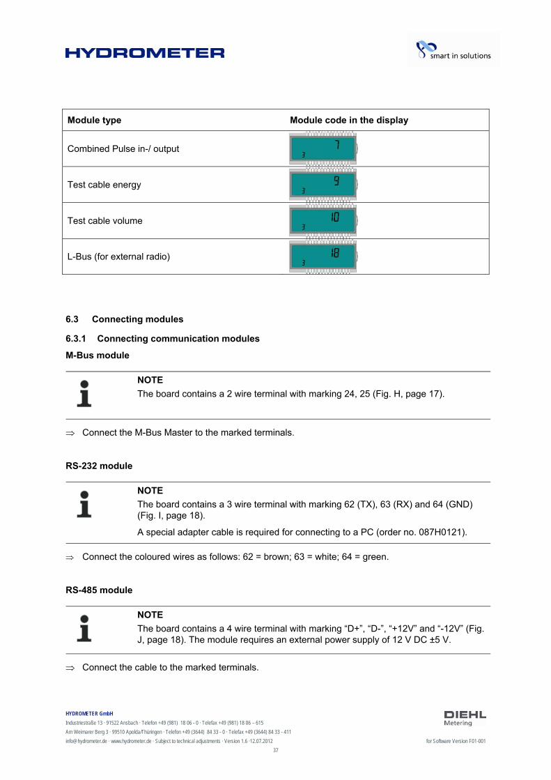
Module type Module code in the display
Combined Pulse in-/ output
Test cable energy
Test cable volume
L-Bus (for external radio)
6.3 Connecting modules
6.3.1 Connecting communication modules
M-Bus module
NOTE
The board contains a 2 wire terminal with marking 24, 25 (Fig. H, page 17).
Connect the M-Bus Master to the marked terminals.
RS-232 module
NOTE
The board contains a 3 wire terminal with marking 62 (TX), 63 (RX) and 64 (GND) (Fig. I, page 18).
A special adapter cable is required for connecting to a PC (order no. 087H0121).
Connect the coloured wires as follows: 62 = brown; 63 = white; 64 = green.
RS-485 module
NOTE
The board contains a 4 wire terminal with marking “D+”, “D-”, “+12V” and “-12V” (Fig. J, page 18). The module requires an external power supply of 12 V DC ±5 V.
Connect the cable to the marked terminals.
HYDROMETER GmbH
Industriestraße 13 · 91522 Ansbach · Telefon +49 (981) 18 06 - 0 · Telefax +49 (981) 18 06 – 615
Am Weimarer Berg 3 · 99510 Apolda/Thüringen · Telefon +49 (3644) 84 33 - 0 · Telefax +49 (3644) 84 33 - 411
[email protected] · www.hydrometer.de · Subject to technical adjustments · Version 1.6 ·12.07.2012 for Software Version F01-001
38
L-Bus module
NOTE
The board contains a 2 wire terminal with marking “Dat“ and ““ (Fig. K, page 19).
Connect the cable of the external radio module with the marked terminals.
6.3.2 Connecting function modules
Pulse input module
NOTE
The board contains a 4 wire terminal with marking “I1 - ” and “I2 - ” (Fig. L, page 19).
Connect the cable for pulse input 1 to terminals “I1 - ” and the cable for pulse input 2 to terminals “I2 - ”.
Pulse output module
NOTE
The board contains a 4 wire terminal with marking “01 - ” and “02 - ” (Fig. N, page 20).
Connect the cable for pulse output 1 to terminals “01” and “” and for pulse output 2 to terminals “02” and “”.
Combined pulse input and output module
NOTE
The board contains a 5 wire terminal for the two pulse inputs with marking “I1 - ” and “I2 - ”. A 3 V DC voltage is connected to the “+” terminal and can be used as the supply for a flow sensor. A 2 wire terminal is also provided for the pulse output with marking “01 - ” (Fig. O, page 21).
Connect the cable for pulse input 1 to terminals “I1 - ” and the cable for pulse input 2 to terminals “I2 - ”.
Connect the cable for the pulse output to terminals “01” and “”.

HYDROMETER GmbH
Industriestraße 13 · 91522 Ansbach · Telefon +49 (981) 18 06 - 0 · Telefax +49 (981) 18 06 – 615
Am Weimarer Berg 3 · 99510 Apolda/Thüringen · Telefon +49 (3644) 84 33 - 0 · Telefax +49 (3644) 84 33 - 411
[email protected] · www.hydrometer.de · Subject to technical adjustments · Version 1.6 ·12.07.2012 for Software Version F01-001
39
Analogue output module
NOTE
The board contains two 2 wire terminals for the two analogue outputs; output 1 is marked “+ 1 –” and output 2 “+ 2 –” (Fig. P, page 22).
Connect the cable for analogue output 1 to the terminals marked “+” and “-” of terminal 1. Connect the cable for the second analogue output to the terminals marked “+” and “-” on terminal 2. Observe the correct polarity.
6.4 Connecting the mains voltage 230 V / 24 V
DANGER
Before you connect the mains cable, be sure that no mains voltage is existing.
Risk of serious injuries or death!
Please take care that the mains voltage corresponds to the mounted mains unit.
Fig. EE Meter with mains unit
1. Remove the top part of the calculator
2. Dismount the terminal cover of the mains unit
3. Install the mains cable via the wire protecting sleeve into the bottom part of the calculator
4. Connect the cable according the labelling of the terminal
5. Reinstall the terminal cover
6. Mount the top part of the calculator back
7. Turn on the mains voltage again
Error E - 8 disappears automatically from the display when the mains voltage is available.
8. The calculator has the be protected against manipulation (sealing)
HYDROMETER GmbH
Industriestraße 13 · 91522 Ansbach · Telefon +49 (981) 18 06 - 0 · Telefax +49 (981) 18 06 – 615
Am Weimarer Berg 3 · 99510 Apolda/Thüringen · Telefon +49 (3644) 84 33 - 0 · Telefax +49 (3644) 84 33 - 411
[email protected] · www.hydrometer.de · Subject to technical adjustments · Version 1.6 ·12.07.2012 for Software Version F01-001
40
6.5 Programming the energy meter
NOTE
A number of settings can be programmed in the meter using the IZAR@SET software. More information is available at www.hydrometer.de.

HYDROMETER GmbH
Industriestraße 13 · 91522 Ansbach · Telefon +49 (981) 18 06 - 0 · Telefax +49 (981) 18 06 – 615
Am Weimarer Berg 3 · 99510 Apolda/Thüringen · Telefon +49 (3644) 84 33 - 0 · Telefax +49 (3644) 84 33 - 411
[email protected] · www.hydrometer.de · Subject to technical adjustments · Version 1.6 ·12.07.2012 for Software Version F01-001
41
7 Taking into operation
The meter can be taken into operation once it has been installed.
Proceed as follows:
Open the stop valves.
Check the system for leaks.
Carefully bleed the system.
The message “E – 7” disappears from the display after a short time.
Check the flow rate and temperature displays for plausibility.
Bleed the system until the flow rate display is steady. Regulate the system using the flow rate display.
Seal the sensors.
Attach the seals to the calculator and temperature sensors.
Read the meter counts for energy, volume and operating hours.
Error messages for wrong installation:
Error display
Meaning
E - 3 Temperature sensors reversed during installation or connection.
E - 6 Meter has not been installed in the intended direction of flow.
NOTE
If the system is idle, these error messages can appear even though the installation has been carried out correctly.
HYDROMETER GmbH
Industriestraße 13 · 91522 Ansbach · Telefon +49 (981) 18 06 - 0 · Telefax +49 (981) 18 06 – 615
Am Weimarer Berg 3 · 99510 Apolda/Thüringen · Telefon +49 (3644) 84 33 - 0 · Telefax +49 (3644) 84 33 - 411
[email protected] · www.hydrometer.de · Subject to technical adjustments · Version 1.6 ·12.07.2012 for Software Version F01-001
42
8 Operation
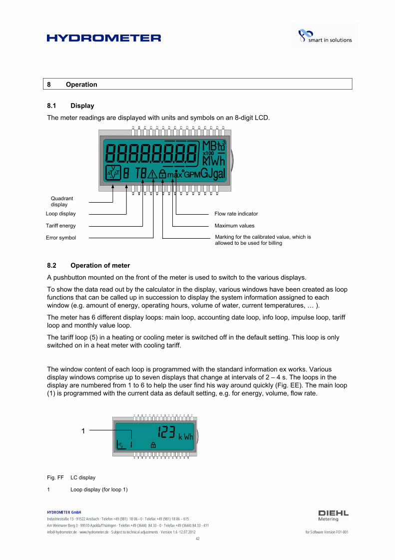
8.1 Display
The meter readings are displayed with units and symbols on an 8-digit LCD.
8.2 Operation of meter
A pushbutton mounted on the front of the meter is used to switch to the various displays.
To show the data read out by the calculator in the display, various windows have been created as loop functions that can be called up in succession to display the system information assigned to each window (e.g. amount of energy, operating hours, volume of water, current temperatures, … ).
The meter has 6 different display loops: main loop, accounting date loop, info loop, impulse loop, tariff loop and monthly value loop.
The tariff loop (5) in a heating or cooling meter is switched off in the default setting. This loop is only switched on in a heat meter with cooling tariff.
The window content of each loop is programmed with the standard information ex works. Various display windows comprise up to seven displays that change at intervals of 2 – 4 s. The loops in the display are numbered from 1 to 6 to help the user find his way around quickly (Fig. EE). The main loop (1) is programmed with the current data as default setting, e.g. for energy, volume, flow rate.
Fig. FF LC display
1 Loop display (for loop 1)
1
Quadrant display
Loop display
Tariff energy
Error symbol
Flow rate indicator
Maximum values
Marking for the calibrated value, which is allowed to be used for billing
HYDROMETER GmbH
Industriestraße 13 · 91522 Ansbach · Telefon +49 (981) 18 06 - 0 · Telefax +49 (981) 18 06 – 615
Am Weimarer Berg 3 · 99510 Apolda/Thüringen · Telefon +49 (3644) 84 33 - 0 · Telefax +49 (3644) 84 33 - 411
[email protected] · www.hydrometer.de · Subject to technical adjustments · Version 1.6 ·12.07.2012 for Software Version F01-001
43
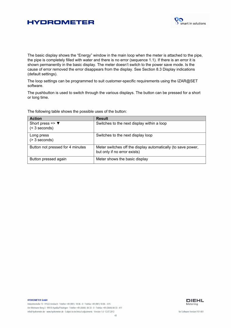
The basic display shows the “Energy” window in the main loop when the meter is attached to the pipe, the pipe is completely filled with water and there is no error (sequence 1.1). If there is an error it is shown permanently in the basic display. The meter doesn’t switch to the power save mode. Is the cause of error removed the error disappears from the display. See Section 8.3 Display indications (default settings).
The loop settings can be programmed to suit customer-specific requirements using the IZAR@SET software.
The pushbutton is used to switch through the various displays. The button can be pressed for a short or long time.
The following table shows the possible uses of the button:
Action Result Short press => (< 3 seconds)
Switches to the next display within a loop
Long press (> 3 seconds)
Switches to the next display loop
Button not pressed for 4 minutes Meter switches off the display automatically (to save power, but only if no error exists)
Button pressed again Meter shows the basic display
HYDROMETER GmbH
Industriestraße 13 · 91522 Ansbach · Telefon +49 (981) 18 06 - 0 · Telefax +49 (981) 18 06 – 615
Am Weimarer Berg 3 · 99510 Apolda/Thüringen · Telefon +49 (3644) 84 33 - 0 · Telefax +49 (3644) 84 33 - 411
[email protected] · www.hydrometer.de · Subject to technical adjustments · Version 1.6 ·12.07.2012 for Software Version F01-001
44
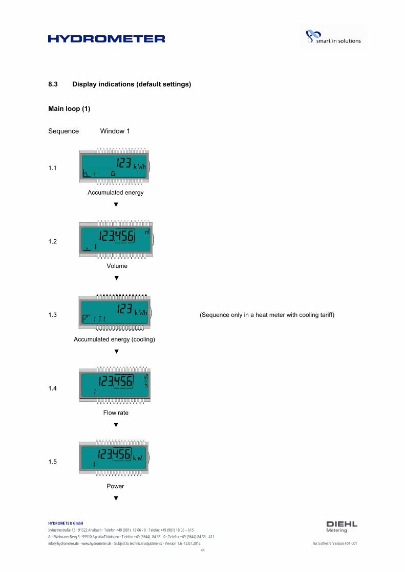
8.3 Display indications (default settings)
Main loop (1)
Sequence Window 1
1.1
Accumulated energy
1.2
Volume
1.3 (Sequence only in a heat meter with cooling tariff)
Accumulated energy (cooling)
1.4
Flow rate
1.5
Power
HYDROMETER GmbH
Industriestraße 13 · 91522 Ansbach · Telefon +49 (981) 18 06 - 0 · Telefax +49 (981) 18 06 – 615
Am Weimarer Berg 3 · 99510 Apolda/Thüringen · Telefon +49 (3644) 84 33 - 0 · Telefax +49 (3644) 84 33 - 411
[email protected] · www.hydrometer.de · Subject to technical adjustments · Version 1.6 ·12.07.2012 for Software Version F01-001
45
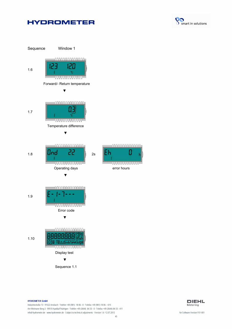
Sequence Window 1
1.6
Forward/- Return temperature
1.7
Temperature difference
1.8 2s
Operating days error hours
1.9
Error code
1.10
Display test
Sequence 1.1
HYDROMETER GmbH
Industriestraße 13 · 91522 Ansbach · Telefon +49 (981) 18 06 - 0 · Telefax +49 (981) 18 06 – 615
Am Weimarer Berg 3 · 99510 Apolda/Thüringen · Telefon +49 (3644) 84 33 - 0 · Telefax +49 (3644) 84 33 - 411
[email protected] · www.hydrometer.de · Subject to technical adjustments · Version 1.6 ·12.07.2012 for Software Version F01-001
46
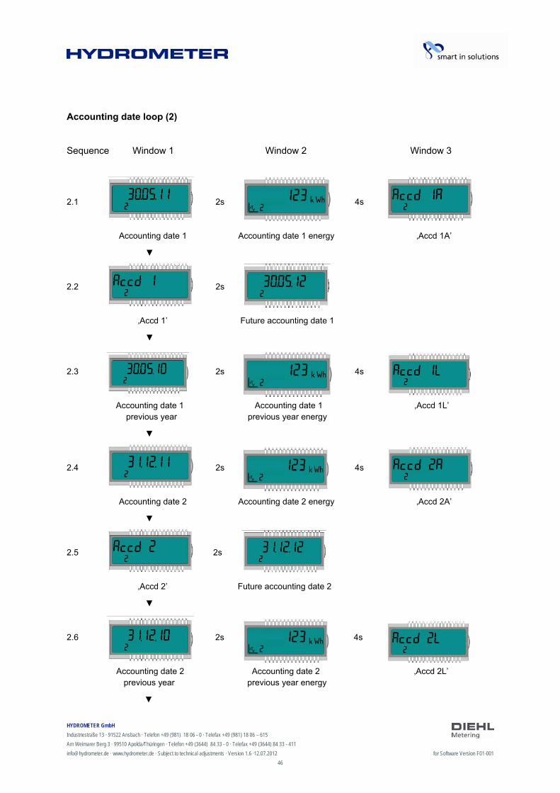
Accounting date loop (2)
Sequence Window 1 Window 2 Window 3
2.1 2s 4s
Accounting date 1 Accounting date 1 energy ‚Accd 1A’
2.2 2s
‚Accd 1’ Future accounting date 1
2.3 2s 4s
Accounting date 1 Accounting date 1 ,Accd 1L’ previous year previous year energy
2.4 2s 4s
Accounting date 2 Accounting date 2 energy ‚Accd 2A’
2.5 2s
‚Accd 2’ Future accounting date 2
2.6 2s 4s
Accounting date 2 Accounting date 2 ‚Accd 2L’ previous year previous year energy
HYDROMETER GmbH
Industriestraße 13 · 91522 Ansbach · Telefon +49 (981) 18 06 - 0 · Telefax +49 (981) 18 06 – 615
Am Weimarer Berg 3 · 99510 Apolda/Thüringen · Telefon +49 (3644) 84 33 - 0 · Telefax +49 (3644) 84 33 - 411
[email protected] · www.hydrometer.de · Subject to technical adjustments · Version 1.6 ·12.07.2012 for Software Version F01-001
47
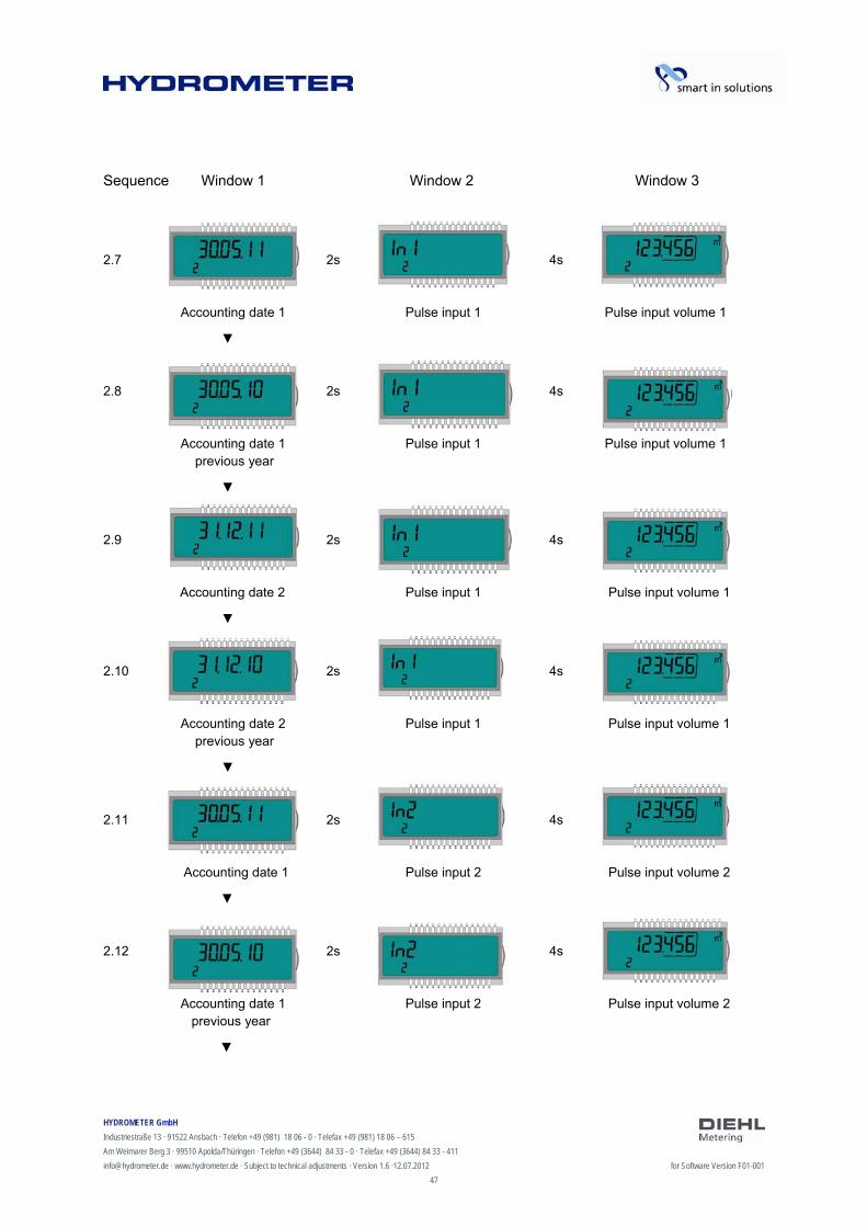
Sequence Window 1 Window 2 Window 3
2.7 2s 4s
Accounting date 1 Pulse input 1 Pulse input volume 1
2.8 2s 4s
Accounting date 1 Pulse input 1 Pulse input volume 1 previous year
2.9 2s 4s
Accounting date 2 Pulse input 1 Pulse input volume 1
2.10 2s 4s
Accounting date 2 Pulse input 1 Pulse input volume 1 previous year
2.11 2s 4s
Accounting date 1 Pulse input 2 Pulse input volume 2
2.12 2s 4s
Accounting date 1 Pulse input 2 Pulse input volume 2 previous year

HYDROMETER GmbH
Industriestraße 13 · 91522 Ansbach · Telefon +49 (981) 18 06 - 0 · Telefax +49 (981) 18 06 – 615
Am Weimarer Berg 3 · 99510 Apolda/Thüringen · Telefon +49 (3644) 84 33 - 0 · Telefax +49 (3644) 84 33 - 411
[email protected] · www.hydrometer.de · Subject to technical adjustments · Version 1.6 ·12.07.2012 for Software Version F01-001
48
Sequence Window 1 Window 2 Window 3
2.13 2s 4s
Accounting date 2 Pulse input 2 Pulse input volume 2
2.14 2s 4s
Accounting date 2 Pulse input 2 Pulse input volume 2 previous year
Sequence 2.1
Info loop (3)
Sequence Window 1 Window 2
3.1 2s
Current date Current time
3.2 2s
‚Sec_Adr.’ Secondary address
3.3 2s
‚Pri_Adr 1’ Primary address 1
3.4 2s
‚Pri_Adr 2’ Primary address 2
HYDROMETER GmbH
Industriestraße 13 · 91522 Ansbach · Telefon +49 (981) 18 06 - 0 · Telefax +49 (981) 18 06 – 615
Am Weimarer Berg 3 · 99510 Apolda/Thüringen · Telefon +49 (3644) 84 33 - 0 · Telefax +49 (3644) 84 33 - 411
[email protected] · www.hydrometer.de · Subject to technical adjustments · Version 1.6 ·12.07.2012 for Software Version F01-001
49
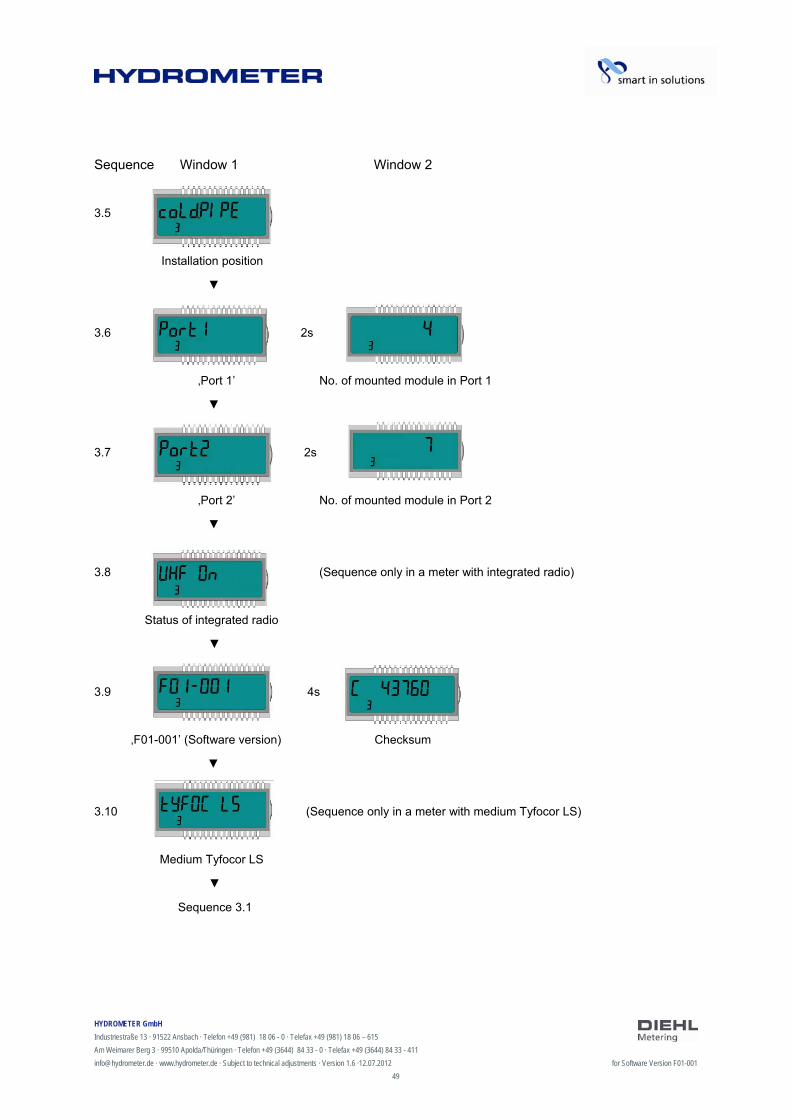
Sequence Window 1 Window 2
3.5
Installation position
3.6 2s
‚Port 1’ No. of mounted module in Port 1
3.7 2s
‚Port 2’ No. of mounted module in Port 2
3.8 (Sequence only in a meter with integrated radio)
Status of integrated radio
3.9 4s
‚F01-001’ (Software version) Checksum
3.10 (Sequence only in a meter with medium Tyfocor LS)
Medium Tyfocor LS
Sequence 3.1
HYDROMETER GmbH
Industriestraße 13 · 91522 Ansbach · Telefon +49 (981) 18 06 - 0 · Telefax +49 (981) 18 06 – 615
Am Weimarer Berg 3 · 99510 Apolda/Thüringen · Telefon +49 (3644) 84 33 - 0 · Telefax +49 (3644) 84 33 - 411
[email protected] · www.hydrometer.de · Subject to technical adjustments · Version 1.6 ·12.07.2012 for Software Version F01-001
50
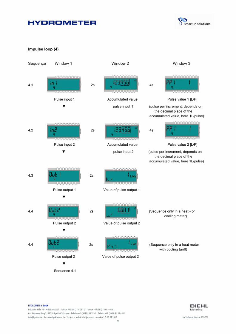
Impulse loop (4)
Sequence Window 1 Window 2 Window 3
4.1 2s 4s
Pulse input 1 Accumulated value Pulse value 1 [L/P]
pulse input 1 (pulse per increment, depends on the decimal place of the accumulated value, here 1L/pulse)
4.2 2s 4s
Pulse input 2 Accumulated value Pulse value 2 [L/P]
pulse input 2 (pulse per increment, depends on the decimal place of the accumulated value, here 1L/pulse)
4.3 2s
Pulse output 1 Value of pulse output 1
4.4 2s (Sequence only in a heat - or cooling meter)
Pulse output 2 Value of pulse output 2
4.4 2s (Sequence only in a heat meter with cooling tariff)
Pulse output 2 Value of pulse output 2
Sequence 4.1
HYDROMETER GmbH
Industriestraße 13 · 91522 Ansbach · Telefon +49 (981) 18 06 - 0 · Telefax +49 (981) 18 06 – 615
Am Weimarer Berg 3 · 99510 Apolda/Thüringen · Telefon +49 (3644) 84 33 - 0 · Telefax +49 (3644) 84 33 - 411
[email protected] · www.hydrometer.de · Subject to technical adjustments · Version 1.6 ·12.07.2012 for Software Version F01-001
51
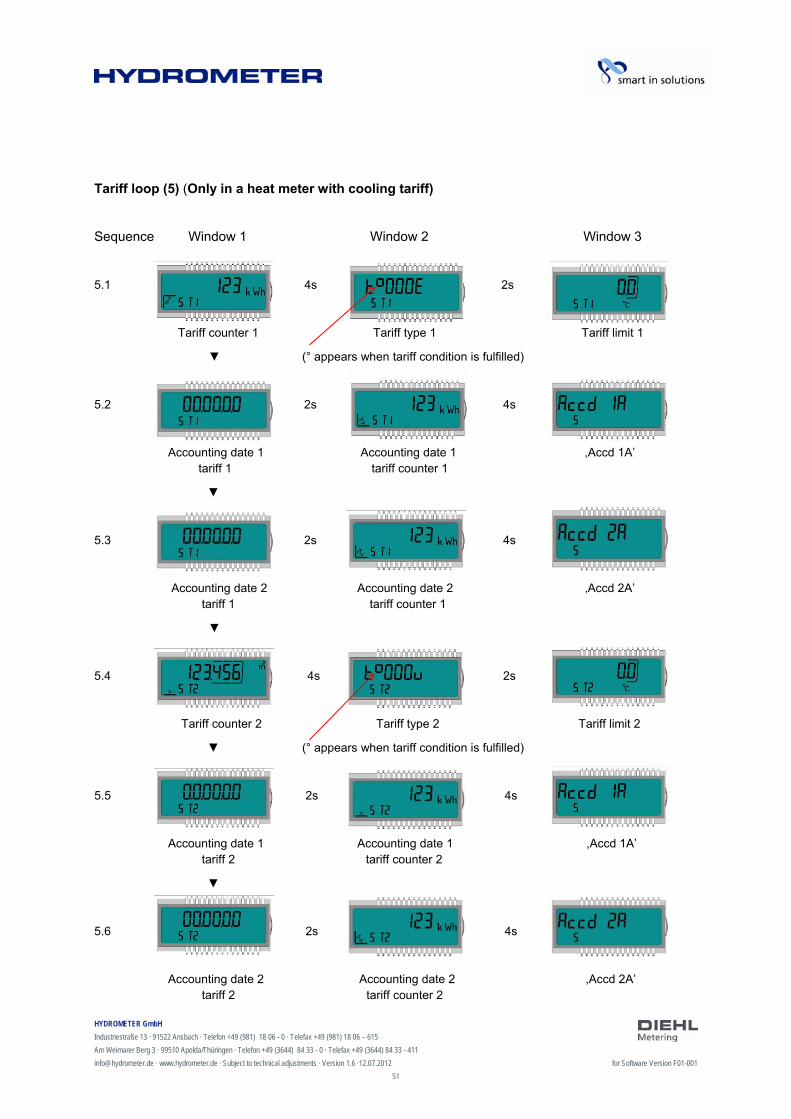
Tariff loop (5) (Only in a heat meter with cooling tariff)
Sequence Window 1 Window 2 Window 3
5.1 4s 2s
Tariff counter 1 Tariff type 1 Tariff limit 1
(° appears when tariff condition is fulfilled)
5.2 2s 4s
Accounting date 1 Accounting date 1 ,Accd 1A’ tariff 1 tariff counter 1
5.3 2s 4s
Accounting date 2 Accounting date 2 ‚Accd 2A’ tariff 1 tariff counter 1
5.4 4s 2s
Tariff counter 2 Tariff type 2 Tariff limit 2
(° appears when tariff condition is fulfilled)
5.5 2s 4s
Accounting date 1 Accounting date 1 ,Accd 1A’ tariff 2 tariff counter 2
5.6 2s 4s
Accounting date 2 Accounting date 2 ,Accd 2A’ tariff 2 tariff counter 2
HYDROMETER GmbH
Industriestraße 13 · 91522 Ansbach · Telefon +49 (981) 18 06 - 0 · Telefax +49 (981) 18 06 – 615
Am Weimarer Berg 3 · 99510 Apolda/Thüringen · Telefon +49 (3644) 84 33 - 0 · Telefax +49 (3644) 84 33 - 411
[email protected] · www.hydrometer.de · Subject to technical adjustments · Version 1.6 ·12.07.2012 for Software Version F01-001
52
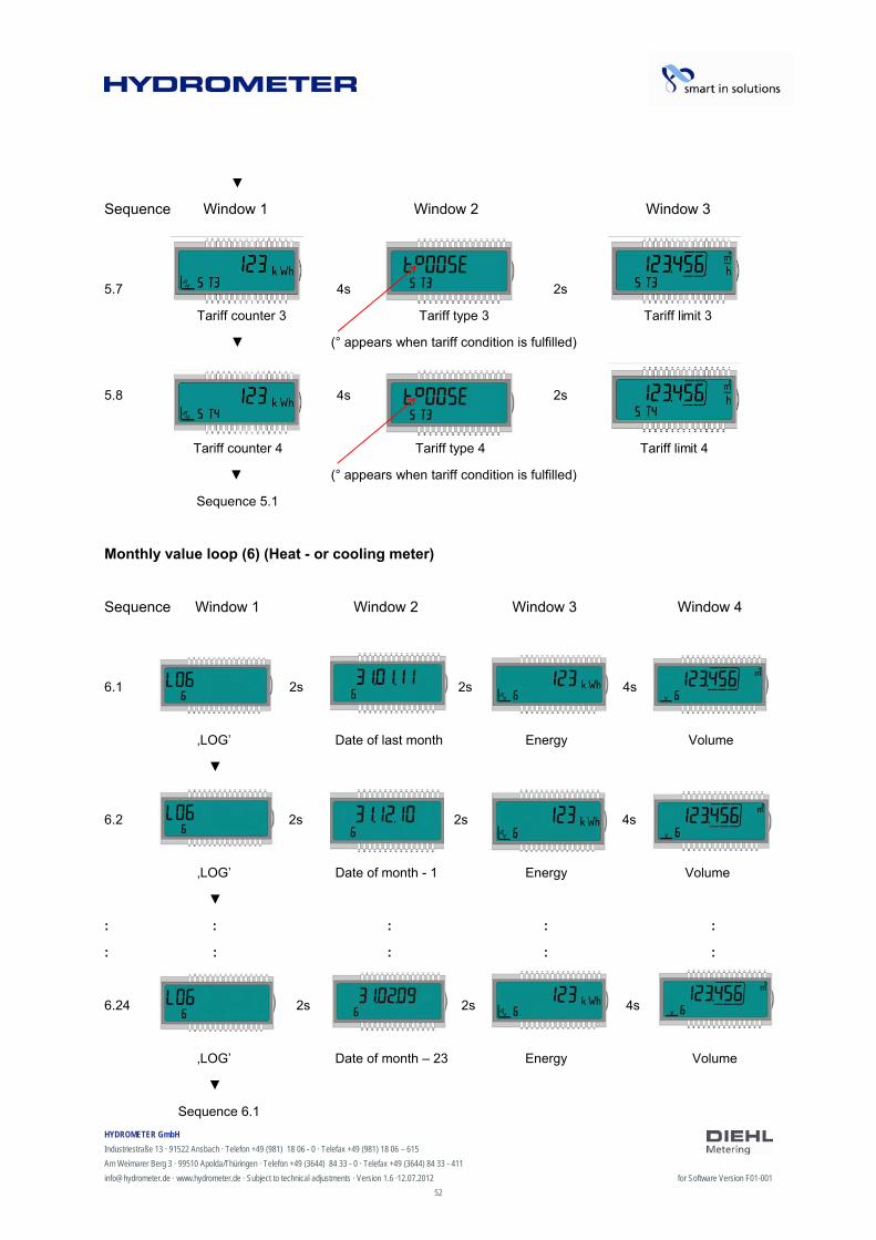
Sequence Window 1 Window 2 Window 3
5.7 4s 2s
Tariff counter 3 Tariff type 3 Tariff limit 3
(° appears when tariff condition is fulfilled)
5.8 4s 2s
Tariff counter 4 Tariff type 4 Tariff limit 4
(° appears when tariff condition is fulfilled)
Sequence 5.1
Monthly value loop (6) (Heat - or cooling meter)
Sequence Window 1 Window 2 Window 3 Window 4
6.1 2s 2s 4s
‚LOG’ Date of last month Energy Volume
6.2 2s 2s 4s
‚LOG’ Date of month - 1 Energy Volume
: : : : :
: : : : :
6.24 2s 2s 4s
‚LOG’ Date of month – 23 Energy Volume
Sequence 6.1
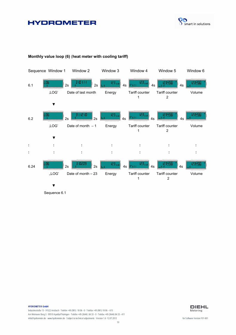
HYDROMETER GmbH
Industriestraße 13 · 91522 Ansbach · Telefon +49 (981) 18 06 - 0 · Telefax +49 (981) 18 06 – 615
Am Weimarer Berg 3 · 99510 Apolda/Thüringen · Telefon +49 (3644) 84 33 - 0 · Telefax +49 (3644) 84 33 - 411
[email protected] · www.hydrometer.de · Subject to technical adjustments · Version 1.6 ·12.07.2012 for Software Version F01-001
53
Monthly value loop (6) (heat meter with cooling tariff)
Sequence Window 1 Window 2 Window 3 Window 4 Window 5 Window 6
6.1 2s 2s 4s 4s 4s
‚LOG’ Date of last month Energy Tariff counter Tariff counter Volume 1 2
6.2 2s 2s 4s 4s 4s
‚LOG’ Date of month – 1 Energy Tariff counter Tariff counter Volume 1 2
: : : : : : :
: : : : : : :
6.24 2s 2s 4s 4s 4s
‚‚LOG’ Date of month – 23 Energy Tariff counter Tariff counter Volume 1 2
Sequence 6.1
HYDROMETER GmbH
Industriestraße 13 · 91522 Ansbach · Telefon +49 (981) 18 06 - 0 · Telefax +49 (981) 18 06 – 615
Am Weimarer Berg 3 · 99510 Apolda/Thüringen · Telefon +49 (3644) 84 33 - 0 · Telefax +49 (3644) 84 33 - 411
[email protected] · www.hydrometer.de · Subject to technical adjustments · Version 1.6 ·12.07.2012 for Software Version F01-001
54
9 Maintenance and repair
NOTE
Information concerning repair and maintenance can be obtained from the Repair Concept.
HYDROMETER GmbH
Industriestraße 13 · 91522 Ansbach · Telefon +49 (981) 18 06 - 0 · Telefax +49 (981) 18 06 – 615
Am Weimarer Berg 3 · 99510 Apolda/Thüringen · Telefon +49 (3644) 84 33 - 0 · Telefax +49 (3644) 84 33 - 411
[email protected] · www.hydrometer.de · Subject to technical adjustments · Version 1.6 ·12.07.2012 for Software Version F01-001
55
10 Testing
NOTE
Information concerning testing can be obtained from the relevant Inspection and Test Instruction.
Test information can also be found in the EC type examination certificate of the meter under 5.1 (Test documentation) and in EN 1434-5. The number of the type examination certificate is printed on the calculator of the meter.

HYDROMETER GmbH
Industriestraße 13 · 91522 Ansbach · Telefon +49 (981) 18 06 - 0 · Telefax +49 (981) 18 06 – 615
Am Weimarer Berg 3 · 99510 Apolda/Thüringen · Telefon +49 (3644) 84 33 - 0 · Telefax +49 (3644) 84 33 - 411
[email protected] · www.hydrometer.de · Subject to technical adjustments · Version 1.6 ·12.07.2012 for Software Version F01-001
56
11 Removal
CAUTION
Danger due to escape of heat medium.
Risk of burns!
Close the stop valves before removing the meter.
Remove the energy meter.
11.1 Disposal of energy meter
NOTE
The meter contains a lithium battery. This must not be opened by force, come into contact with water, be short-circuited or exposed to temperatures above 85 °C. Used batteries and electronic equipment or components no longer required are to be handled as special waste.
Dismantle energy meter.
Dispose of the individual parts of the meter at a suitable waste collection point.

HYDROMETER GmbH
Industriestraße 13 · 91522 Ansbach · Telefon +49 (981) 18 06 - 0 · Telefax +49 (981) 18 06 – 615
Am Weimarer Berg 3 · 99510 Apolda/Thüringen · Telefon +49 (3644) 84 33 - 0 · Telefax +49 (3644) 84 33 - 411
[email protected] · www.hydrometer.de · Subject to technical adjustments · Version 1.6 ·12.07.2012 for Software Version F01-001
57
12 Error analysis
The meter continuously monitors its own operation and displays various error messages. The error code is displayed in the main loop if an error occurs. The permanent display shown corresponds to the “normal” display (e.g. a temperature sensor error is not shown in the flow rate display). In the basic display mode, the display changes between error codes 1, 4 and 7 and the basic display (exception: error display “C - 1” is shown permanently). All the other windows can still be selected by pressing the button.
The error display disappears automatically as soon as the cause of the error has been cleared. All errors present longer than 6 minutes are saved in the error log.
The following table shows the error codes indicated in the display with their respective meaning:
Error display Meaning
C - 1 Basic parameter error in flash or RAM
E - 1 Temperature measurement error
- Temperature range exceeded [-9.9 °C … 190 °C] - Sensor short-circuit - Sensor break
E - 3** Temperature sensors reversed in hot and cold lines
E - 4 Hardware error in ultrasonic measurement
- Ultrasonic transducer defective - Short-circuit in ultrasonic transducer
E - 5 Reading too frequently
- M-Bus communication not possible for short time
E - 6** Wrong direction of flow
Flow sensor incorrectly installed
E - 7 No meaningful ultrasonic receive signal
- Air in the measuring path
E - 8 No primary voltage (only if mains unit used)
- Powered by back-up battery
E - 9 Warning: battery nearly exhausted
E - A* Leakage: pipe break detected
E - b* Leakage: leakage detected in energy meter
E - C* Leakage: leakage pulse input 1
E - d* Leakage: leakage pulse input 2
* optional
** application-dependent
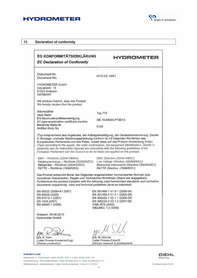
HYDROMETER GmbH
Industriestraße 13 · 91522 Ansbach · Telefon +49 (981) 18 06 - 0 · Telefax +49 (981) 18 06 – 615
Am Weimarer Berg 3 · 99510 Apolda/Thüringen · Telefon +49 (3644) 84 33 - 0 · Telefax +49 (3644) 84 33 - 411
[email protected] · www.hydrometer.de · Subject to technical adjustments · Version 1.6 ·12.07.2012 for Software Version F01-001
58
13 Declaration of conformity
HYDROMETER GmbH
Industriestraße 13 · 91522 Ansbach · Telefon +49 (981) 18 06 - 0 · Telefax +49 (981) 18 06 – 615
Am Weimarer Berg 3 · 99510 Apolda/Thüringen · Telefon +49 (3644) 84 33 - 0 · Telefax +49 (3644) 84 33 - 411
[email protected] · www.hydrometer.de · Subject to technical adjustments · Version 1.6 ·12.07.2012 for Software Version F01-001
59