

SHAPER Model by TI-14 INVICTA - J & G · PDF fileTI-14 V.05 TILTING SPINDLE / SLIDING TABLE...
28
OPERATORS MANUAL SHAPER by INVICTA Model TI-14 INCLUDES VERSIONS: TI-14 V.02 NON-TILTING TI-14 V.03 TILTING SPINDLE TI-14 V.04 SLIDING TABLE TI-14 V.05 TILTING SPINDLE / SLIDING TABLE INVICTA USA English Version (877) 308-6423 – East Revision Nº 01 (800) 499-4682 - West
Transcript of SHAPER Model by TI-14 INVICTA - J & G · PDF fileTI-14 V.05 TILTING SPINDLE / SLIDING TABLE...
OPERATORS MANUAL
SHAPERbyINVICTA
ModelTI-14
INCLUDES VERSIONS:TI-14 V.02 NON-TILTINGTI-14 V.03 TILTING SPINDLE TI-14 V.04 SLIDING TABLE TI-14 V.05 TILTING SPINDLE / SLIDING TABLE
INVICTA USA English Version (877) 308-6423 – East Revision Nº 01(800) 499-4682 - West
SHAPER Model TI-14
General Instructions
As with all equipment, safety is to be a priority. The operator should understand the safety features and apply good safety habits in transportation, adjustment, maintenance and operation of the machine. Practice and teach others the safe operating procedures of this machine and help to prevent the possibility of accidents.
Safety Rules
1. For your own safety, read carefully the Instruction Manual before attempting to operate the machine. 2. If you are not thoroughly familiar and comfortable with the adjustment and operation of the machine, ask for
instruction from your supervisor or a fully qualified person. You may also contact Invicta USA.3. Before the initial operation of the machine, remove all packaging, shipping grease and fully assemble the
machine. Pay special attention to the assembly of safety components. 4. Wear proper apparel while operating the machine. Never wear loose fitting clothing, gloves or ties. Always
remove rings or other jewelry before operating the machine. It is strongly suggested the operator wear shoes with non-slip soles and also wear a protective hair net to prevent hair entanglement in moving parts.
5. Always wear personal safety equipment. Follow the safety regulations of your country and your company. 6. Have a certified person make all wiring connections to power source and properly ground the machine. 7. Always disconnect the machine from the power source and use lockout procedures before servicing,
changing cutting tools and during any cleaning of the machine. 8. Before starting the machine, be aware that the work area is clean and free of debris. Cluttered areas are
invitations for accidents to occur. . 9. Keep the safety guard(s) of the machine in place and in proper working condition. Never operate
machinery without safety equipment in place. Report any damage to your supervisor. Keep children and visitors a safe distance from the working area.
10. Never leave the machine running while unattended. Turn off the power source during breaks. The machine should come to a complete stop before walking away.
11. Do not operate the machine under the influence of drugs or alcohol. Consult your physician when taking medications.
12. Do not force the machine beyond its limitations. It will produce a nicer and safer job and at the rate it was designed to operate.
Additional Safety Rules for the Operation of Shapers
1) Avoid Kickbacks. “Kickback” can occur when the workpiece is forced back by the cutter during improper operation. When “Kickback” occurs an injury can result. Some of the causes of Kickback are: A- Improper tooling
B- Knots, Nails or Imperfections in the workpiece. C- Heavier Cuts than the machine was designed for.
D- Failure to use the material hold downs and or a powerfeeder with thin or narrow workpieces. 2) Always maintain the proper relationship of in-feed fence and the out-feed fence in relation to the Cutterhead. 3) Never start the work-piece into the cutterhead before allowing it to reach operation speed. 4) Keep the cutter sharp and free of rust and pitch 5) Never use an unbalanced cutterhead or an improper speed for the cutterhead. 6) Support and control the workpiece properly all times during the operation. 7) Never reverse the direction of the workpiece after beginning operation. Kickback can occur. 8) Always use the diameter spindle that is the correct size for your cutter. 9) When changing cutterheads be sure to replace the cutter guard before operation. 10) Check for proper rotation after each cutter change and the beginning of work. 11) Mounting of large diameter cutterheads should be as close to the base of the spindle as possible. 12) Keep the work area as clean as possible to avoid slipping or tripping. 13) Never place loose items on the table top while in operation. 14 Never continue to operate equipment that is in need of repair. 15) Safety glasses are strongly recommended during operation. 01
SHAPER Mod. TI-14
Electrical Connections of the Machine
Each machine is provided with a reference plate that indicates the requirements of the electrical service needed for the machine to properly operate. Before you call a certified electrician to make the wiring connections, be sure that the voltage and cycle (phase) stated on this reference plate are the same as provided in your building.
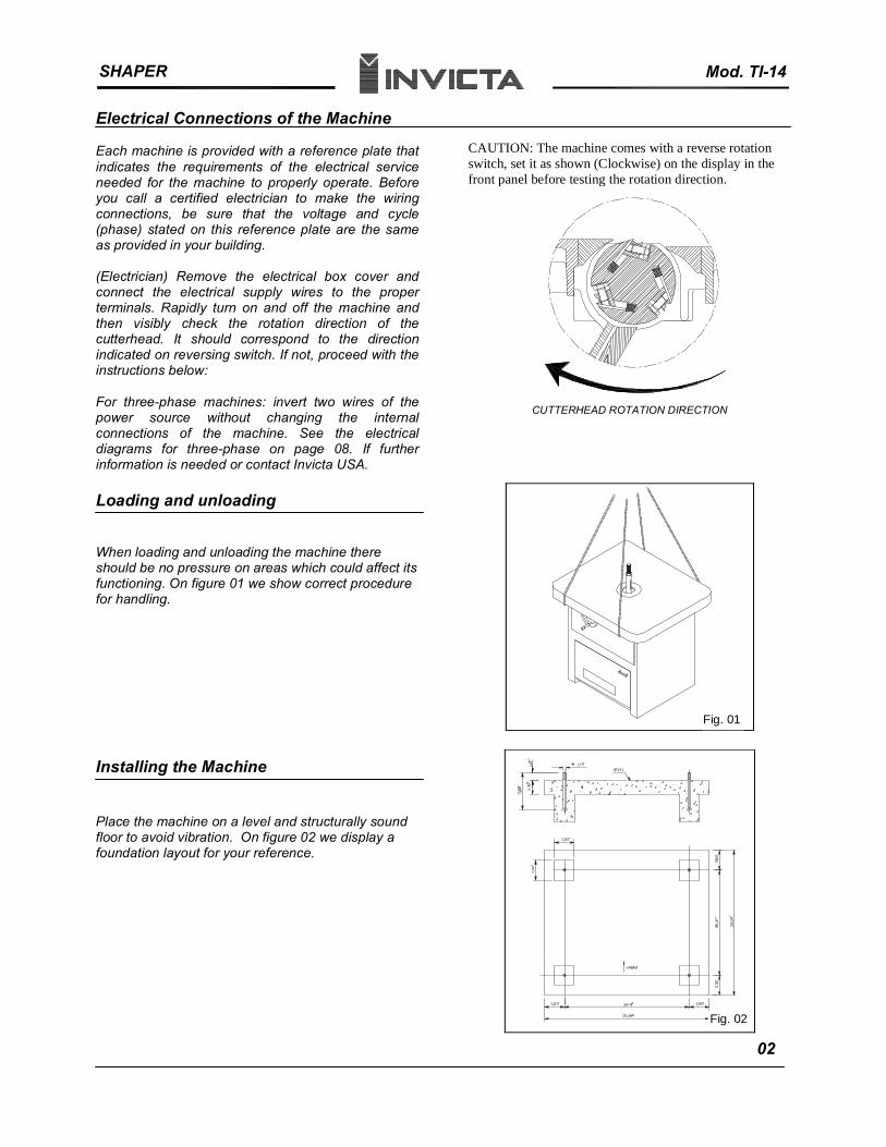
(Electrician) Remove the electrical box cover and connect the electrical supply wires to the proper terminals. Rapidly turn on and off the machine and then visibly check the rotation direction of the cutterhead. It should correspond to the direction indicated on reversing switch. If not, proceed with the instructions below:
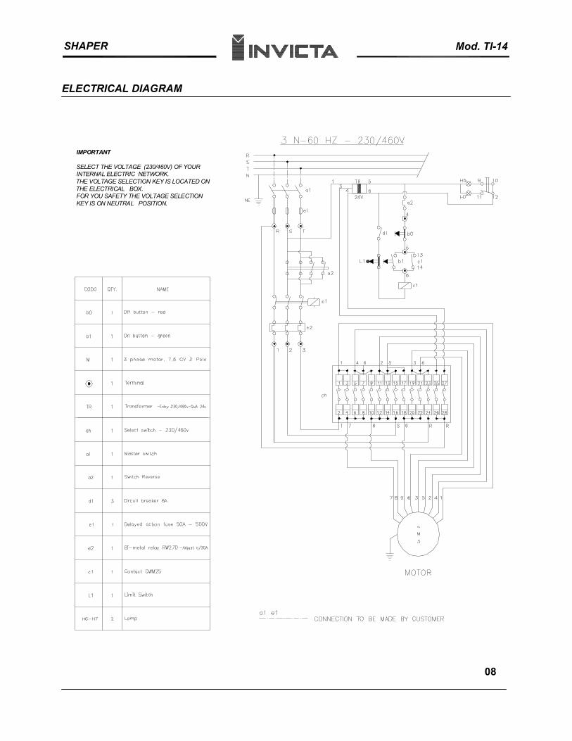
For three-phase machines: invert two wires of the power source without changing the internal connections of the machine. See the electrical diagrams for three-phase on page 08. If further information is needed or contact Invicta USA.
Loading and unloading
When loading and unloading the machine there should be no pressure on areas which could affect its functioning. On figure 01 we show correct procedure for handling.
Installing the Machine
Place the machine on a level and structurally sound floor to avoid vibration. On figure 02 we display a foundation layout for your reference.
CAUTION: The machine comes with a reverse rotation switch, set it as shown (Clockwise) on the display in the front panel before testing the rotation direction.
CUTTERHEAD ROTATION DIRECTION
Fig. 01
Fig. 02
02
SHAPER Technical Specification
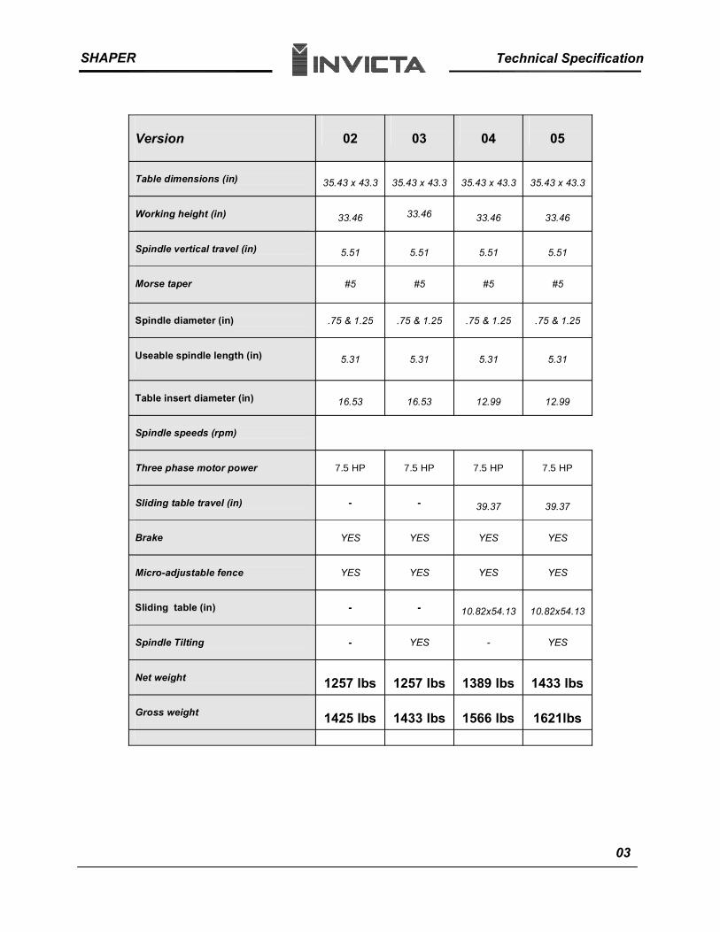
Version 02 03 04 05
35.43 x 43.3 35.43 x 43.3 35.43 x 43.3 35.43 x 43.3Table dimensions (in)
33.46 33.46 33.46 33.46Working height (in)
Spindle vertical travel (in) 5.51 5.51 5.51 5.51
Morse taper #5 #5 #5 #5
Spindle diameter (in) .75 & 1.25 .75 & 1.25 .75 & 1.25 .75 & 1.25
Useable spindle length (in) 5.31 5.31 5.31 5.31
Table insert diameter (in) 16.53 16.53 12.99 12.99
Spindle speeds (rpm)
Three phase motor power 7.5 HP 7.5 HP 7.5 HP 7.5 HP
Sliding table travel (in) - - 39.37 39.37
Brake YES YES YES YES
Micro-adjustable fence YES YES YES YES
Sliding table (in) - - 10.82x54.13 10.82x54.13
Spindle Tilting - YES - YES
Net weight 1257 lbs 1257 lbs 1389 lbs 1433 lbs
Gross weight 1425 lbs 1433 lbs 1566 lbs 1621lbs
03
SHAPER Changing the Spindle
INVICTA TECHNICAL BULLETIN Subject: Correct Procedure for Changing Spindles
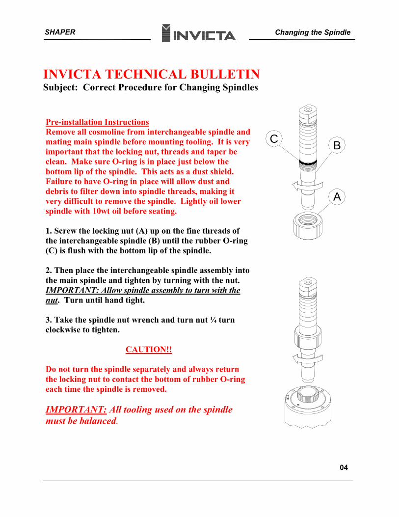
Pre-installation InstructionsRemove all cosmoline from interchangeable spindle and mating main spindle before mounting tooling. It is very important that the locking nut, threads and taper be clean. Make sure O-ring is in place just below the bottom lip of the spindle. This acts as a dust shield.Failure to have O-ring in place will allow dust and debris to filter down into spindle threads, making it very difficult to remove the spindle. Lightly oil lower spindle with 10wt oil before seating.
1. Screw the locking nut (A) up on the fine threads of the interchangeable spindle (B) until the rubber O-ring (C) is flush with the bottom lip of the spindle.
2. Then place the interchangeable spindle assembly into the main spindle and tighten by turning with the nut. IMPORTANT: Allow spindle assembly to turn with the nut. Turn until hand tight.
3. Take the spindle nut wrench and turn nut ¼ turn clockwise to tighten.
CAUTION!!
Do not turn the spindle separately and always return the locking nut to contact the bottom of rubber O-ring each time the spindle is removed.
IMPORTANT: All tooling used on the spindle must be balanced.
C B
A
04
SHAPER Mod. TI-14
Accessories
1 Special wrench 1 Open end wrench 38 mm 1 Open end wrench 10 x 13 mm 1 Open end wrench 19 x 24 mm 1 Open end wrench 24 x 27 mm 1 Allen wrench 5 mm 1 Cutter Shaft(Spindle) Ø3/4” with rings 1 Cutter Shaft(Spindle) Ø1 1/4” with rings1 Allen wrech 14 mm 1 Instruction manual
Lubrication
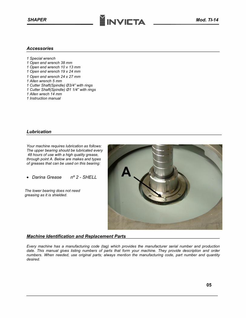
Your machine requires lubrication as follows: The upper bearing should be lubricated every 48 hours of use with a high quality grease, through point A. Below are makes and types of greases that can be used on this bearing:
Darina Grease nº 2 - SHELL
The lower bearing does not need greasing as it is shielded.
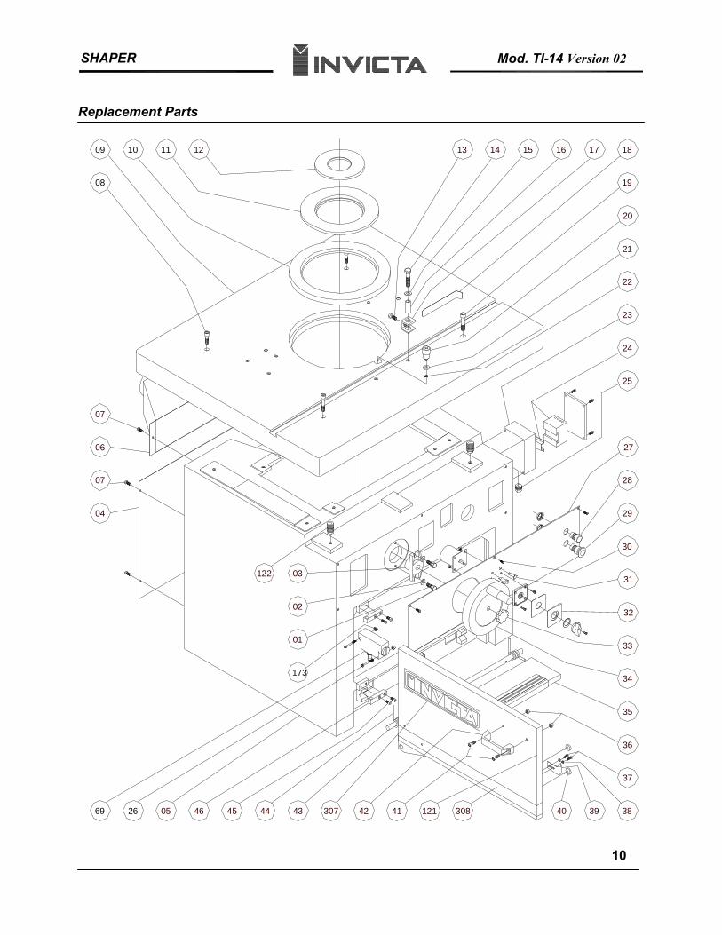
Machine Identification and Replacement Parts
A
Every machine has a manufacturing code (tag) which provides the manufacturer serial number and production date. This manual gives listing numbers of parts that form your machine. They provide description and order numbers. When needed, use original parts; always mention the manufacturing code, part number and quantity desired.
05
SHAPER Mod. TI-14
Adjustment Instructions
Controls
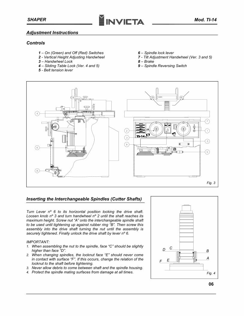
1 – On (Green) and Off (Red) Switches 6 – Spindle lock lever 2 - Vertical Height Adjusting Handwheel 7 - Tilt Adjustment Handwheel (Ver. 3 and 5) 3 – Handwheel Lock 8 – Brake4 – Sliding Table Lock (Ver. 4 and 5) 9 – Spindle Reversing Switch 5 - Belt tension lever
CD
F E A
B
Inserting the Interchangeable Spindles (Cutter Shafts)
Fig. 3
Turn Lever nº 6 to its horizontal position locking the drive shaft. Loosen knob nº 3 and turn handwheel nº 2 until the shaft reaches its maximum height. Screw nut “A” onto the interchangeable spindle shaft to be used until tightening up against rubber ring “B”. Then screw this assembly into the drive shaft turning the nut until the assembly is securely tightened. Finally unlock the drive shaft by lever nº 6.
IMPORTANT:1. When assembling the nut to the spindle, face “C” should be slightly
higher than face “D”. 2. When changing spindles, the locknut face “E” should never come
in contact with surface “F”. If this occurs, change the relation of the locknut to the shaft before tightening.
3. Never allow debris to come between shaft and the spindle housing.4. Protect the spindle mating surfaces from damage at all times. Fig. 4
06
SHAPER Mod. TI-14
G
Change Speeds and Adjustment of Belt Tension
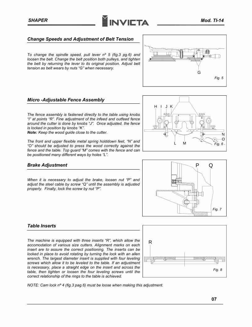
To change the spindle speed, pull lever nº 5 (fig.3 pg.6) and loosen the belt. Change the belt position both pulleys, and tighten the belt by returning the lever to its original position. Adjust belt tension as belt wears by nuts “G” when necessary.
Micro -Adjustable Fence Assembly
The fence assembly is fastened directly to the table using knobs “I” at points “R”. Fine adjustment of the infeed and outfeed fence around the cutter is done by knobs “J”. Once adjusted, the fence is locked in position by knobs “K”. Note: Keep the wood guide close to the cutter.
The front and upper flexible metal spring holddown feet, “N” and “O” should be adjusted to press the wood correctly against the fence and the table. Top guard “M” comes with the fence and can be positioned many different ways by holes “L”.
Brake Adjustment
When it is necessary to adjust the brake, loosen nut “P” and adjust the steel cable by screw “Q” until the assembly is adjusted properly. Finally, lock the screw by nut “P”.
Table Inserts
Fig. 5
J
NO
H I K
ML Fig. 6
P Q
Fig. 7
RThe machine is equipped with three inserts “R”, which allow the accomodation of various size cutters. Alignment marks on each insert are to assure the correct positioning. The inserts can be locked in place to avoid rotating by turning the lock with an allen wrench. The largest diameter insert is supplied with four leveling screws which allow it to be leveled to the table. If an adjustment is necessary, place a straight edge on the insert and across the table, then tighten or loosen the four leveling screws until the correct relationship of the rings to the table is achieved.
NOTE: Cam lock nº 4 (fig.3 pag.6) must be loose when making this adjustment.
Fig. 8
07
SHAPER Mod. TI-14
ELECTRICAL DIAGRAM
IMPORTANT
SELECT THE VOLTAGE (230/460V) OF YOUR INTERNAL ELECTRIC NETWORK.THE VOLTAGE SELECTION KEY IS LOCATED ON THE ELECTRICAL BOX.FOR YOU SAFETY THE VOLTAGE SELECTION KEY IS ON NEUTRAL POSITION.
08
SHAPER Mod. TI-14
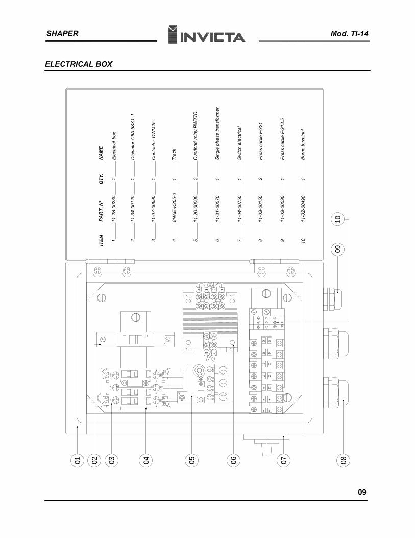
ELECTRICAL BOX
71
0201 03 04
A1
1 L1
A1
1-2-
2 T1
05 06
A2
96 N
C
PAR
T. N
°
11-2
8-00
230
11-3
4-00
120
11-0
7-00
690
11-3
1-00
070
8NA
E-K
205-
0
11-2
0-00
090
3 L2
A2 5
L3
3NO
4NO
3-
4 T2
4-
6 T3
A2 95 N
C97
NO
98 N
O
5 6
21
ITEM 3
4 13 2
4 5 6S
ingl
e ph
ase
trans
form
er
NA
ME
Ele
ctric
al b
ox
Dis
junt
or C
6A 5
SX
1-1
Con
tact
or C
WM
25
1
QTY
.
1 1
Trac
k
Ove
rload
rela
y R
W27
D
1 2 1
07
1 2
5 6
08
11-0
3-00
150
11-0
3-00
090
11-0
2-00
490
9 10
13 14
17 18
21 22
25 26
879
8 9
09
Pre
ss c
able
PG
13.5
Pre
ss c
able
PG
21
Bor
ne te
rmin
al
2 1 1
10
10
11-0
4-00
750
Sw
itch
elec
trica
l
09
SHAPER Mod. TI-14 Version 02
Replacement Parts
30769 0526 46 45 44 43
01
173
02
03122
07
04
07
06
08
09 10 11 12
38
37
36
35
4142 121 308 3940
34
33
29
28
30
32
31
27
18
19
20
22
21
23
24
25
13 1514 16 17
10
SHAPER Mod. TI-14 Version 02 & 04
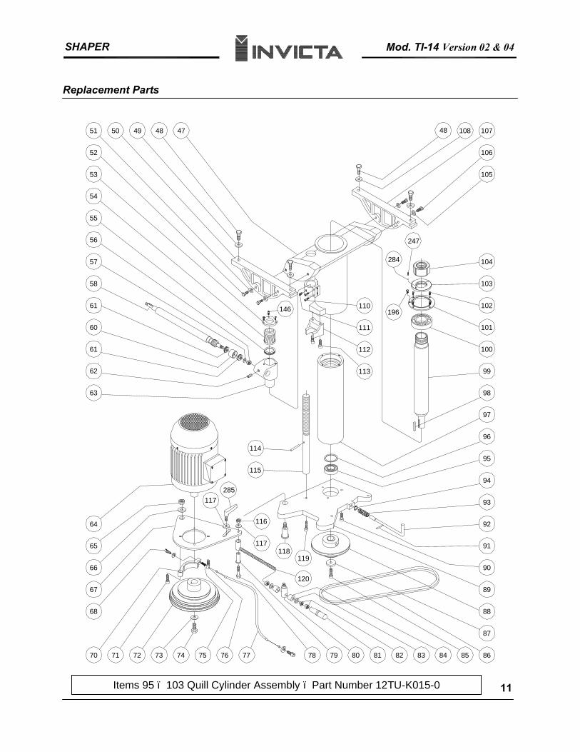
Replacement Parts
66
7170
67
68
72 73
64
65
62
63
61
61
60
57
58
54
56
55
52
53
5051 49 48
95
74 75 7776 78 79 80 838281 84 85
90
86
87
88
89
91
92
93
94
113
110
111
112
47
96
97
98
99
102
101
100
103
104
48 108
105
106
107
115
114
117
116
120
119118
146 196
284
247
285117
Items 95 – 103 Quill Cylinder Assembly – Part Number 12TU-K015-0 11
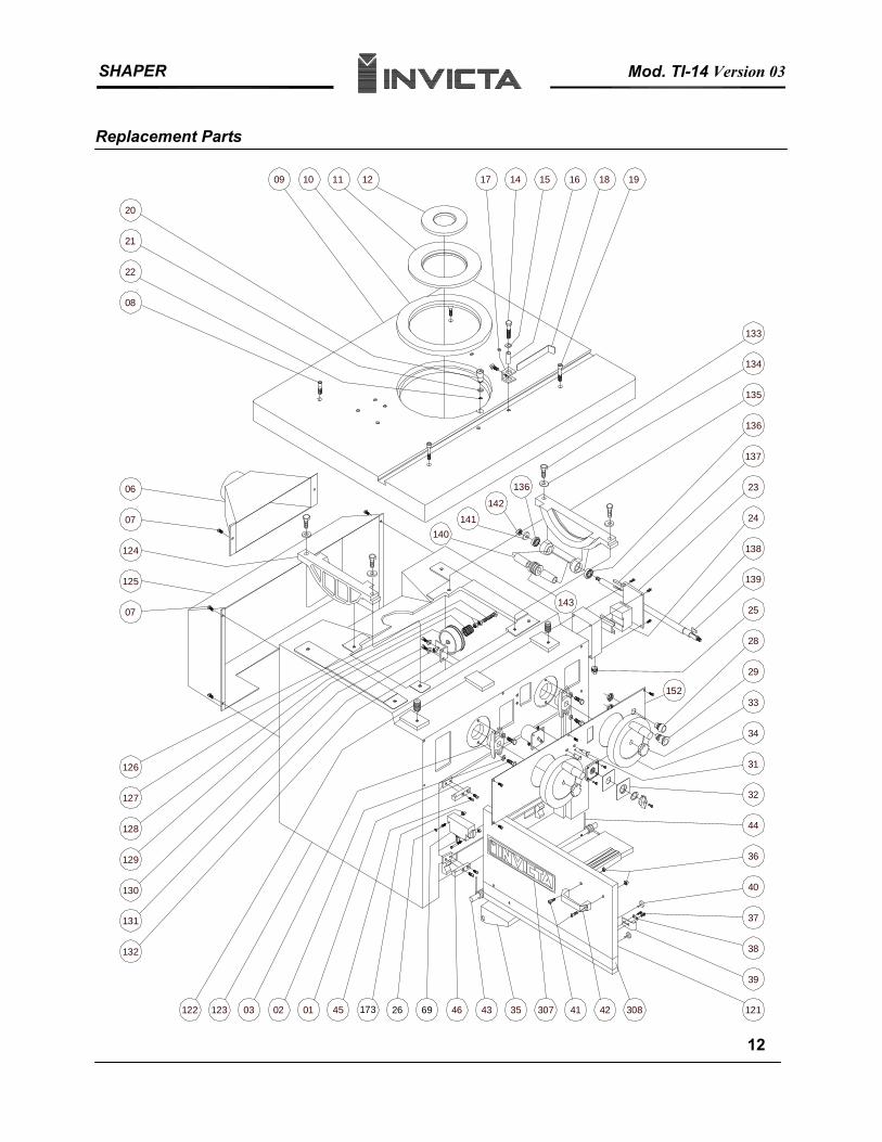
SHAPER Mod. TI-14 Version 03
Replacement Parts
129
132
130
131
123 03 02
127
128
126
07
36
4501 46 43 35 41 42 121
39
38
37
40
143
32
44
31
34
33
29
28
25
125
124
07
06
08
22
21
20
09 10 11 12
133
140141
142
136
139
138
24
23
135
136
137
134
17 14 15 16 1918
122
152
173 26 69 307 308
12
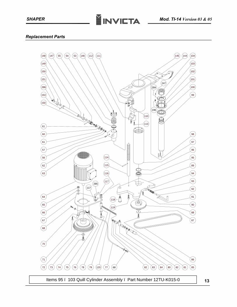
SHAPER Mod. TI-14 Version 03 & 05
Replacement Parts
119
118
116
117
115
114
148
113
110
147 55 54 53 146 112 111
149
150
151
286
153
150
145 144 104
103
102
101
100
99
61
60
61
57
56
62
63
64
65
66
67
68
70
71
72 73 74 75 76 78 79 120 77 82 83 84 80 82 81 85
86
87
88
90
91
92
93
94
89
95
96
97
98
196
284
247
285117
68
Items 95 – 103 Quill Cylinder Assembly – Part Number 12TU-K015-0 13
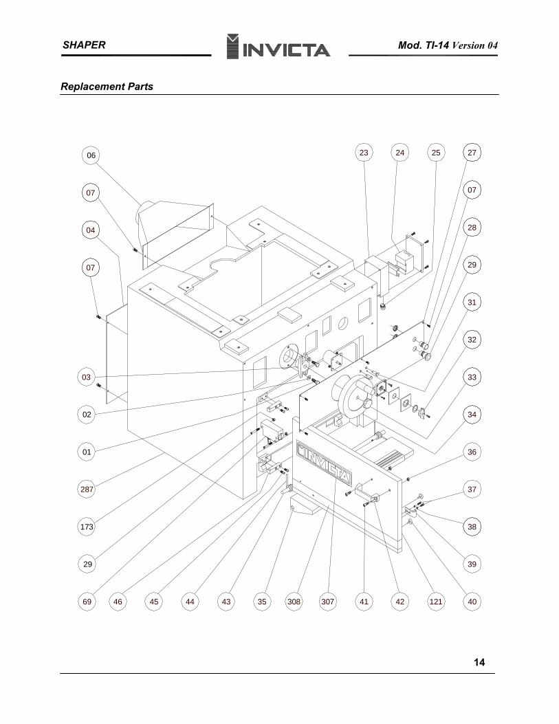
SHAPER Mod. TI-14 Version 04
Replacement Parts
40
39
37
38
34
36
1214235 4146 45 44 43
29
69
33
32
31
29
28
07
173
27252423
287
06
07
04
07
03
02
01
307308
14
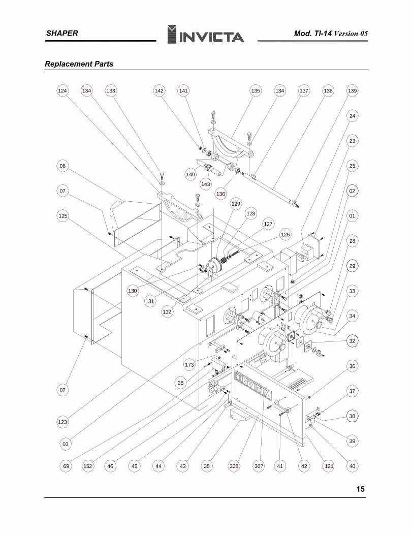
SHAPER Mod. TI-14 Version 05
Replacement Parts
40
139
39
37
38
32
36
34
29
33
28
02
01
25
1214235 4146 45 44 43
138137135 134142 141133134124
125
07
06
152
07
23
24
126
127
128
129
136
143
140
131
132
130
03
123
69
173
26
307308
15
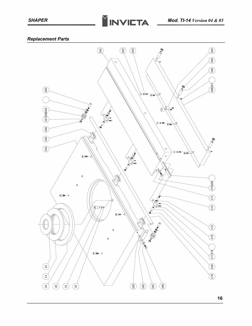
SHAPER Mod. TI-14 Version 04 & 05
Replacement Parts 12
2210 2120
11
183
181
182
180
179
1771
7617
417
517
117
217
0169
166
1681
6716
5
162
163
164
160
1571
5815
915
615
515
4
161
159
16
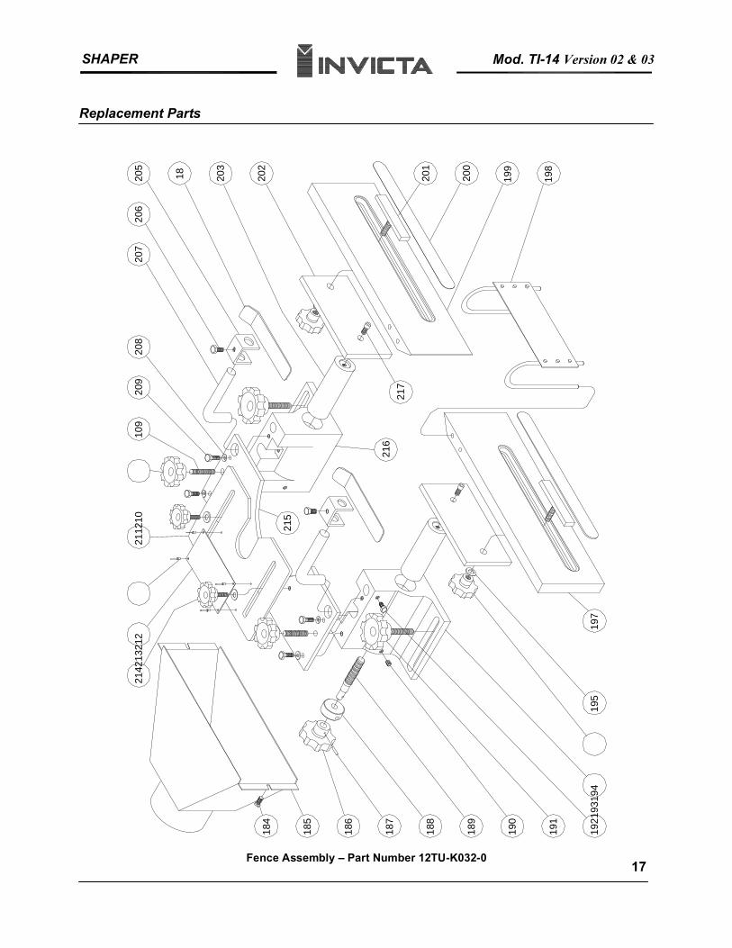
SHAPER Mod. TI-14 Version 02 & 03
Replacement Parts
2142
1321
210
9
185
186
187
190
188
189
191
1921
9319
4
217
207
208
206
18205
203
201
200
199
198
216
202
215
184
195
197
209
2112
10
Fence Assembly – Part Number 12TU-K032-0 17
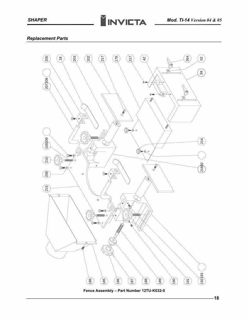
SHAPER Mod. TI-14 Version 04 & 05
Replacement Parts
186
187
190
188
189
191
1921
93
2072
06
18205
203
185
186
208
215
1092
09
202
217
217
178
42
2160
2
264
0259
214
210
Fence Assembly – Part Number 12TU-K032-0
18
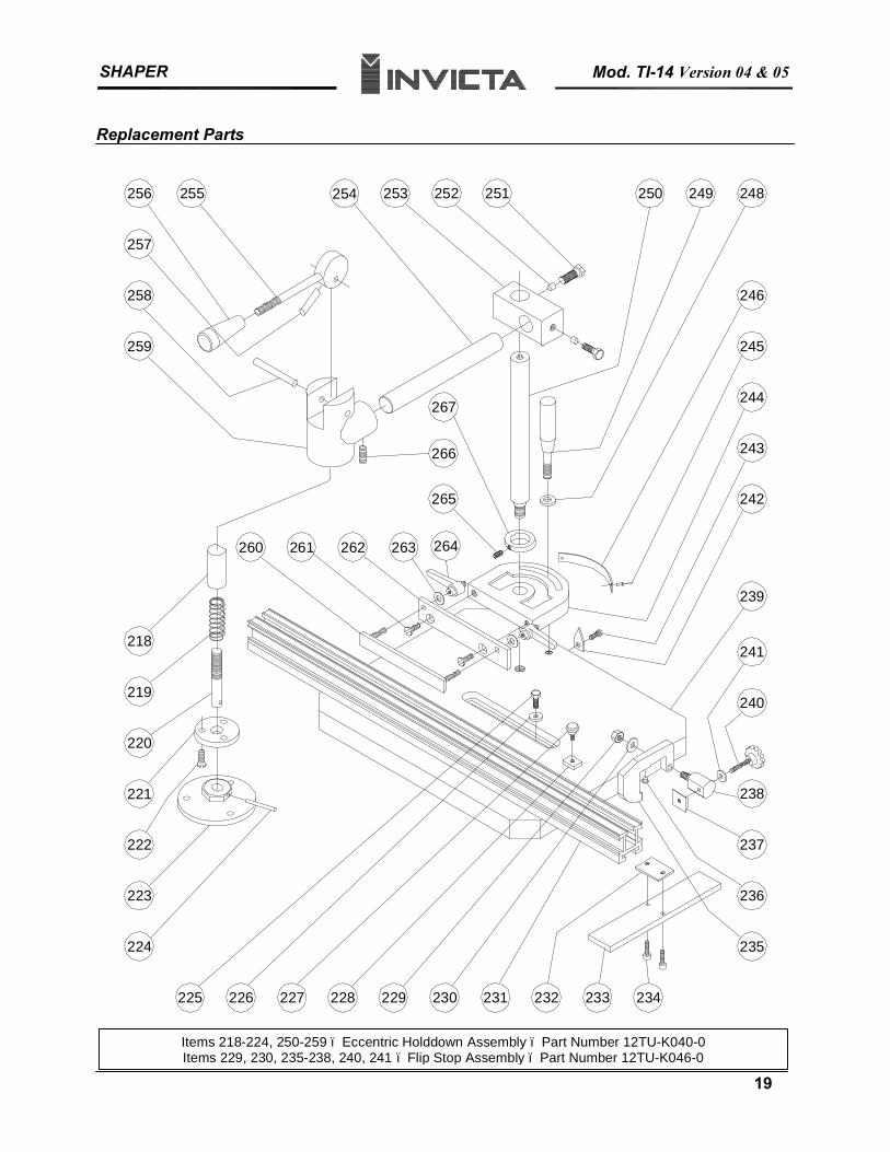
SHAPER Mod. TI-14 Version 04 & 05
Replacement Parts
228
222
224
226225 227
223
221
220
219
237
234231229 230 232 233
235
236
238
240
254
218
260 261
259
258
257
256 255
263262
265
241
242
266
267244
243
245
250251253 252
246
249 248
264
239
19
19
Items 218-224, 250-259 – Eccentric Holddown Assembly – Part Number 12TU-K040-0 Items 229, 230, 235-238, 240, 241 – Flip Stop Assembly – Part Number 12TU-K046-0
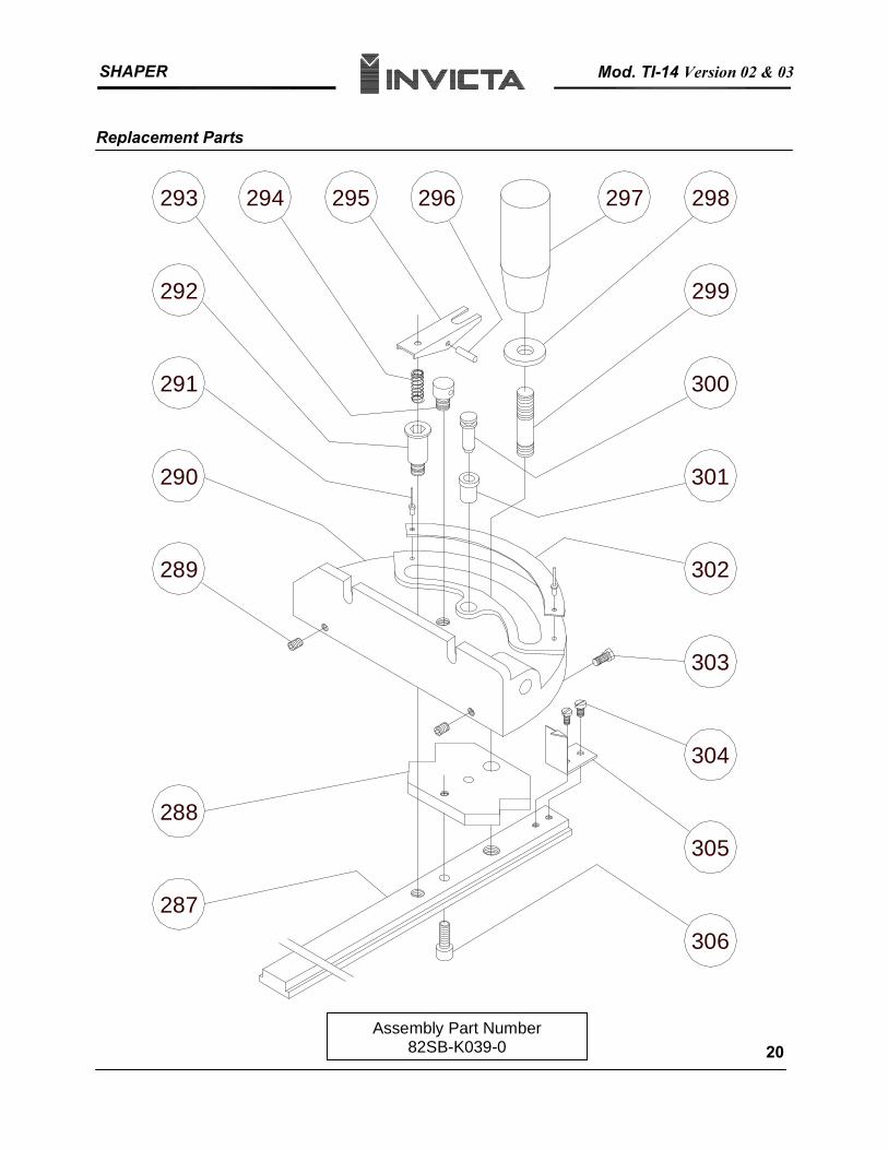
SHAPER Mod. TI-14 Version 02 & 03
Replacement Parts
287
288
294
291
290
292
293 295 296
303
305
304
297
302
301
300
298
299
306
289
Assembly Part Number 82SB-K039-0 20
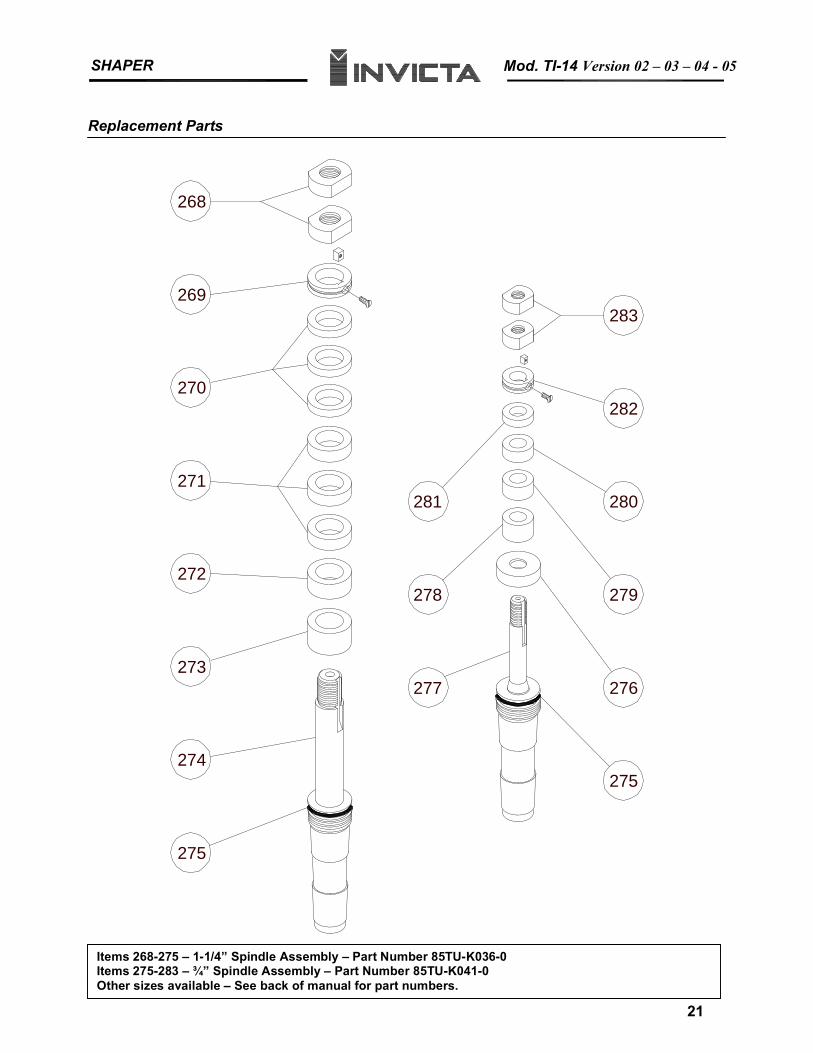
SHAPER Mod. TI-14 Version 02 – 03 – 04 - 05
Replacement Parts
275
276
279
280
282
283
281
278
277
275
274
273
272
271
270
269
268
21
21
Items 268-275 – 1-1/4” Spindle Assembly – Part Number 85TU-K036-0 Items 275-283 – ¾” Spindle Assembly – Part Number 85TU-K041-0 Other sizes available – See back of manual for part numbers.
SHAPER Mod. TI-14
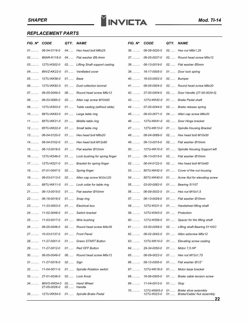
REPLACEMENT PARTS
FIG. Nº CODE QTY. NAME FIG. Nº CODE QTY. NAME
01.......... 06-04-0119-0 04…... Hex head bolt M8x25 36……... 06-09-0020-0 02…... Hex nut M8x1,25
02.......... 8NAR-K118-0 04…... Flat washer Ø8,4mm 37……... 06-05-0037-0 02…... Round head screw M5x12
03.......... 12TU-K502-0 02…... Lifting Shaft support casting 38……... 06-13-0019-0 02…... Flat washer Ø5mm
04.......... 8NVZ-KK22-0 01…... Ventilated cover 39……... 16-17-0005-0 01…... Door lock spring
05……... 12TU-KK58-0 01…... Base 40……... 16-03-0002-0 02…... Bumper
06……... 12TU-KK92-0 01…... Dust collection bonnet 41……... 06-05-0004-0 02…... Round head screw M8x20
07……... 06-05-0049-0 06…... Round head screw M6x12 42……... 27-00-0004-0 02…... Door Handle (27-00-0024-0)
08……... 06-03-0085-0 02…... Allen cap screw M10x90 43……... 12TU-KK42-0 01…... Brake Pedal shaft
09……... 12TU-K503-0 01…... Table casting (without slide) 44……... 07-00-0044-0 02…... Brake release spring
10……... 89TU-KK83-0 01…... Large table ring 45……... 06-03-0071-0 04…... Allen cap screw M6x20
11……... 85TU-KK21-0 01…... Middle table ring 46……... 12TU-KK41-0 02…... Door Hinge bracket
12……... 85TU-KK22-0 01…... Small table ring 47……... 12TU-KK13-0 01…... Spindle Housing Bracket
13……... 06-04-0120-0 01…... Hex head bolt M8x20 48……... 06-04-0089-0 02…... Hex head bolt M10x50
14……... 06-04-0102-0 01…... Hex head bolt M12x60 49……... 06-13-0015-0 02…... Flat washer Ø10mm
15……... 06-13-0016-0 01…... Flat washer Ø12mm 50……... 12TU-KK10-0 01…... Spindle Housing Support left
16……... 12TU-K549-0 01…... Lock bushing for spring finger 51……... 06-13-0015-0 02…... Flat washer Ø10mm
17……... 12TU-K527-0 01…... Bracket for spring finger 52……... 06-04-0122-0 02…... Hex head bolt M10x60
18……... 07-01-0047-0 02…... Spring finger 53…….... 85TU-KK42-0 01…... Cover of the nut housing
19……... 06-03-0113-0 02…... Allen cap screw M10x120 54……... 85TU-KK40-0 01…... Acme Nut for elevating screw
20……... 89TU-KK11-0 01…... Lock collar for table ring 55……... 03-00-0062-0 01…... Bearing 51107
21……... 06-13-0015-0 01…... Flat washer Ø10mm 56……... 06-09-0032-0 01…... Hex nut M10x1,5
22……... 06-18-0018-0 01…... Snap ring 57……... 06-13-0026-0 01…... Flat washer Ø10mm
23……... 11-33-0003-0 01…... Electrical box 58……... 12TU-K531-0 01…... Handwheel lifting shaft
24……... 11-02-0048-0 01…... Switch bracket 59……... 12TU-K543-0 01…... Protection
25……... 11-03-0017-0 01…... Wire bushing 60……... 12TU-K558-0 01…... Spacer for the lifting shaft
26……... 06-05-0046-0 02…... Round head screw M4x35 61……... 03-00-0058-0 02…... Lifting shaft Bearing 51102C
27……... 10-03-0137-0 01…... Front Panel 62……... 06-02-0042-0 01…... Allen setscrew M6x12
28……... 11-27-0001-0 01…... Green START Button 63……... 12TU-KK14-0 01…... Elevating screw casting
29……... 11-27-0012-0 01…... Red OFF Button 64……... 29-34-0050-0 01…... Motor 7,5 HP
30……... 06-05-0049-0 06…... Round head screw M6x12 65……... 06-09-0022-0 01…... Hex nut M12x1,75
31……... 11-27-0016-0 02…... Sign 66……... 06-13-0005-0 01…... Flat washer Ø1/2”
32……... 11-04-0011-0 01…... Spindle Rotation switch 67……... 12TU-KK18-0 01…... Motor base bracket
33……... 27-01-0036-0 02…... Lock Knob 68……... 16-09-0005-0 01…... Brake cable tension screw
34……... 8NVO-KK54-0 02…... Hand Wheel 69……... 11-04-0012-0 01…... Stop27-05-0026-0 02…... Handle
35……... 12TU-KK54-0 01…... Spindle Brake Pedal 70……... 12TU-KKK5-0
12TU-K023-0 01…...01…...
Brake shoe assembly Brake/Cable/ Nut assembly
22
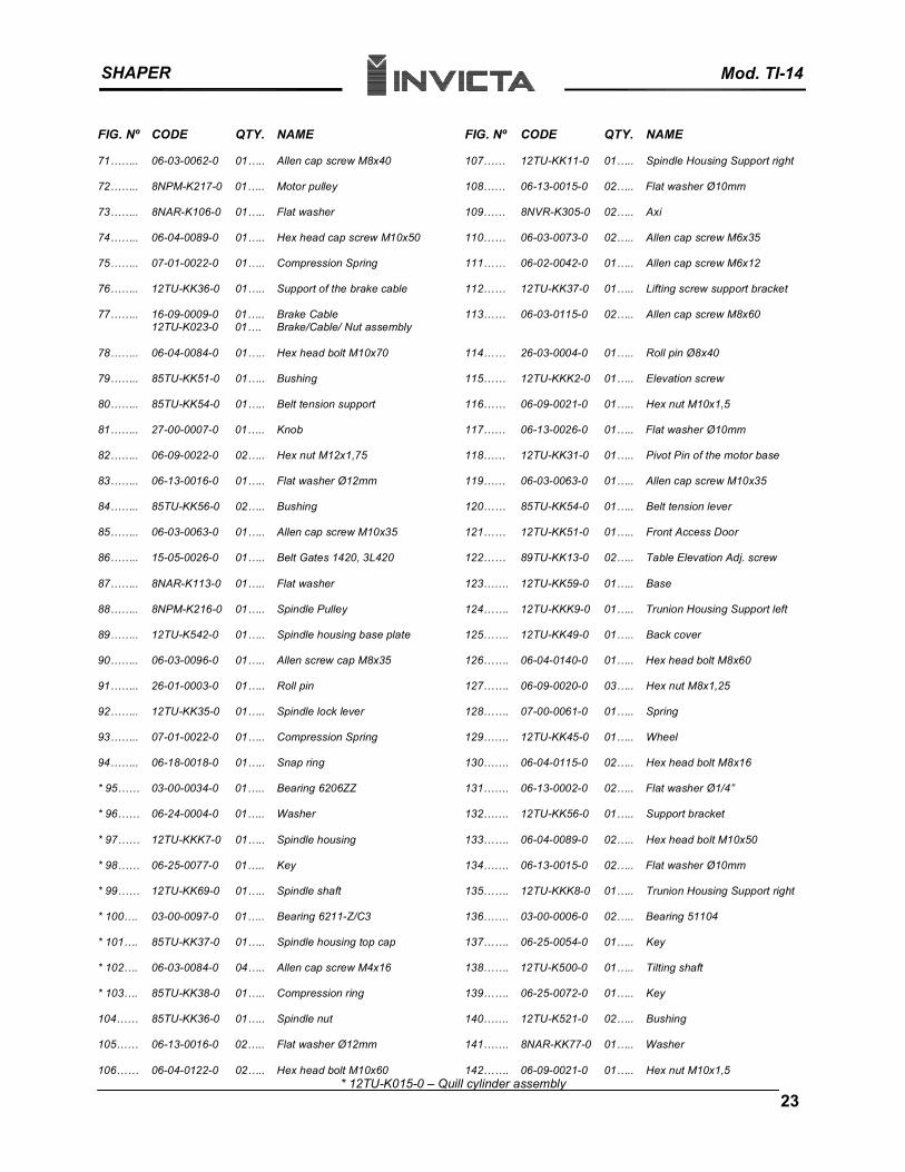
SHAPER Mod. TI-14
FIG. Nº CODE QTY. NAME FIG. Nº CODE QTY. NAME
71…….. 06-03-0062-0 01….. Allen cap screw M8x40 107…… 12TU-KK11-0 01….. Spindle Housing Support right
72…….. 8NPM-K217-0 01….. Motor pulley 108…… 06-13-0015-0 02….. Flat washer Ø10mm
73…….. 8NAR-K106-0 01….. Flat washer 109…… 8NVR-K305-0 02….. Axi
74…….. 06-04-0089-0 01….. Hex head cap screw M10x50 110…… 06-03-0073-0 02….. Allen cap screw M6x35
75…….. 07-01-0022-0 01….. Compression Spring 111…… 06-02-0042-0 01….. Allen cap screw M6x12
76…….. 12TU-KK36-0 01….. Support of the brake cable 112…… 12TU-KK37-0 01….. Lifting screw support bracket
77…….. 16-09-0009-0 12TU-K023-0
01…..01….
Brake Cable Brake/Cable/ Nut assembly
113…… 06-03-0115-0 02….. Allen cap screw M8x60
78…….. 06-04-0084-0 01….. Hex head bolt M10x70 114…… 26-03-0004-0 01….. Roll pin Ø8x40
79…….. 85TU-KK51-0 01….. Bushing 115…… 12TU-KKK2-0 01….. Elevation screw
80…….. 85TU-KK54-0 01….. Belt tension support 116…… 06-09-0021-0 01….. Hex nut M10x1,5
81…….. 27-00-0007-0 01….. Knob 117…… 06-13-0026-0 01….. Flat washer Ø10mm
82…….. 06-09-0022-0 02….. Hex nut M12x1,75 118…… 12TU-KK31-0 01….. Pivot Pin of the motor base
83…….. 06-13-0016-0 01….. Flat washer Ø12mm 119…… 06-03-0063-0 01….. Allen cap screw M10x35
84…….. 85TU-KK56-0 02….. Bushing 120…… 85TU-KK54-0 01….. Belt tension lever
85…….. 06-03-0063-0 01….. Allen cap screw M10x35 121…… 12TU-KK51-0 01….. Front Access Door
86…….. 15-05-0026-0 01….. Belt Gates 1420, 3L420 122…… 89TU-KK13-0 02….. Table Elevation Adj. screw
87…….. 8NAR-K113-0 01….. Flat washer 123……. 12TU-KK59-0 01….. Base
88…….. 8NPM-K216-0 01….. Spindle Pulley 124……. 12TU-KKK9-0 01….. Trunion Housing Support left
89…….. 12TU-K542-0 01….. Spindle housing base plate 125……. 12TU-KK49-0 01….. Back cover
90…….. 06-03-0096-0 01….. Allen screw cap M8x35 126……. 06-04-0140-0 01….. Hex head bolt M8x60
91…….. 26-01-0003-0 01….. Roll pin 127……. 06-09-0020-0 03….. Hex nut M8x1,25
92…….. 12TU-KK35-0 01….. Spindle lock lever 128……. 07-00-0061-0 01….. Spring
93…….. 07-01-0022-0 01….. Compression Spring 129……. 12TU-KK45-0 01….. Wheel
94…….. 06-18-0018-0 01….. Snap ring 130……. 06-04-0115-0 02….. Hex head bolt M8x16
* 95…… 03-00-0034-0 01….. Bearing 6206ZZ 131……. 06-13-0002-0 02….. Flat washer Ø1/4”
* 96…… 06-24-0004-0 01….. Washer 132……. 12TU-KK56-0 01….. Support bracket
* 97…… 12TU-KKK7-0 01….. Spindle housing 133……. 06-04-0089-0 02….. Hex head bolt M10x50
* 98…… 06-25-0077-0 01….. Key 134……. 06-13-0015-0 02….. Flat washer Ø10mm
* 99…… 12TU-KK69-0 01….. Spindle shaft 135……. 12TU-KKK8-0 01….. Trunion Housing Support right
* 100…. 03-00-0097-0 01….. Bearing 6211-Z/C3 136……. 03-00-0006-0 02….. Bearing 51104
* 101…. 85TU-KK37-0 01….. Spindle housing top cap 137……. 06-25-0054-0 01….. Key
* 102…. 06-03-0084-0 04….. Allen cap screw M4x16 138……. 12TU-K500-0 01….. Tilting shaft
* 103…. 85TU-KK38-0 01….. Compression ring 139……. 06-25-0072-0 01….. Key
104…… 85TU-KK36-0 01….. Spindle nut 140……. 12TU-K521-0 02….. Bushing
105…… 06-13-0016-0 02….. Flat washer Ø12mm 141……. 8NAR-KK77-0 01….. Washer
106…… 06-04-0122-0 02….. Hex head bolt M10x60 142……. 06-09-0021-0 01….. Hex nut M10x1,5 * 12TU-K015-0 – Quill cylinder assembly
23
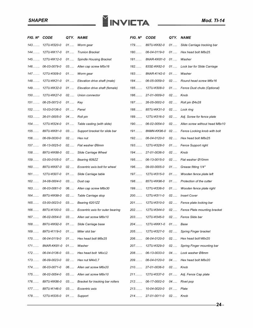
SHAPER Mod. TI-14
FIG. Nº CODE QTY. NAME FIG. Nº CODE QTY. NAME
143……. 12TU-K520-0 01….. Worm gear 179…… 89TU-KK82-0 01….. Slide Carriage tracking bar
Hex head bolt M8x25144……. 12TU-KK17-0 01….. Trunion Bracket 180…… 06-04-0119-0 01…..
145……. 12TU-KK12-0 01….. Spindle Housing Bracket 181…… 8NAR-KK81-0 01….. Washer
146……. 06-03-0079-0 03….. Allen cap screw M5x16 182…… 83SE-KK62-0 01….. Lock bar for Slide Carriage
147……. 12TU-K509-0 01….. Worm gear 183…… 8NAR-K142-0 01….. Washer
148……. 12TU-KK21-0 01….. Elevation drive shaft (male) 184…… 06-05-0059-0 02….. Round head screw M6x16
149……. 12TU-KK32-0 01….. Elevation drive shaft (female) 185……. 12TU-K508-0 01….. Fence Dust chute (Optional)
150……. 12TU-KK27-0 02….. Union connector 186……. 27-01-0009-0 02….. Knob
151……. 06-25-0072-0 01….. Key 187……. 26-05-0002-0 02….. Roll pin Ø4x28
152……. 10-03-0136-0 01….. Panel 188……. 85TU-KK31-0 02….. Lock ring
153……. 26-01-0005-0 04….. Roll pin 189……. 12TU-K516-0 02….. Adj. Screw for fence plate
154…… 12TU-K524-0 01….. Table casting (with slide) 190……. 06-02-0054-0 02….. Allen screw without head M8x10
155…… 89TU-KK81-0 03….. Support bracket for slide bar 191……. 8NMN-KK96-0 02….. Fence Locking knob with bolt
156…… 06-09-0030-0 02….. Hex nut 192……. 06-04-0120-0 02….. Hex head bolt M8x25
157…… 06-13-0025-0 02….. Flat washer Ø8mm 193……. 12TU-K528-0 01….. Fence Support right
158…… 89TU-KK88-0 02….. Slide Carriage Wheel 194……. 27-01-0036-0 02….. Knob
159…… 03-00-0105-0 07….. Bearing 609ZZ 195……. 06-13-0015-0 02….. Flat washer Ø10mm
160…… 89TU-KK87-0 02….. Eccentric axis bolt for wheel 196……. 09-00-0005-0 01….. Grease fitting 1/4"
161…… 12TU-K507-0 01….. Slide Carriage table 197……. 12TU-K515-0 01….. Wooden fence plate left
162…… 24-08-0004-0 03….. Dust cap 198……. 85TU-KK96-0 01….. Protection of the cutter
163…… 06-03-0061-0 06….. Allen cap screw M8x30 199……. 12TU-K536-0 01….. Wooden fence plate right
164…… 89TU-KK99-0 02….. Table Carriage stop 200……. 12TU-K511-0 02….. Insert Cover
165…… 03-00-0023-0 03….. Bearing 6201ZZ 201……. 12TU-K510-0 02….. Fence plate locking bar
166…… 89TU-K100-0 03….. Eccentric axis for outer bearing 202……. 12TU-K544-0 02….. Fence Plate mounting bracket
167…… 06-02-0054-0 03….. Allen set screw M8x10 203……. 12TU-K545-0 02….. Fence Slide bar
168…… 89TU-KK92-0 01….. Slide Carriage base 204……. 12TU-KKK1-0 01….. Base
169…… 89TU-K119-0 01….. Miter slot bar 205……. 12TU-K527-0 02….. Spring Finger bracket
Hex head bolt M8x20 170…… 06-04-0119-0 01….. Hex head bolt M8x25 206……. 06-04-0120-0 02…..
171…… 8NAR-KK81-0 01….. Washer 207……. 12TU-K529-0 02….. Spring Finger mounting bar
172…… 06-04-0136-0 03….. Hex head bolt M6x12 208……. 06-13-0033-0 04….. Lock washer Ø8mm
173…… 06-09-0023-0 02….. Hex nut M4x0,7 209……. 06-04-0120-0 04….. Hex head bolt M8x20
174…… 06-03-0071-0 06….. Allen set screw M6x20 210……. 27-01-0036-0 02….. Knob
175…… 06-02-0054-0 03….. Allen set screw M8x10 211……. 12TU-K537-0 01….. Adj. Fence Cap plate
176…… 89TU-KK86-0 03….. Bracket for tracking bar rollers 212……. 06-17-0002-0 04….. Rivet pop
177…… 89TU-K146-0 03….. Eccentric axis 213……. 10-04-0020-0 01….. Plate
178…… 12TU-K535-0 01….. Support 214……. 27-01-0011-0 02….. Knob
24
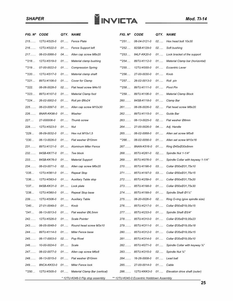
SHAPER Mod. TI-14
FIG. Nº CODE QTY. NAME FIG. Nº CODE QTY. NAME
215…… 12TU-K525-0 01….. Fence Plate **251…. 06-04-0121-0 02….. Hex head bolt 10x30
216…… 12TU-K522-0 01….. Fence Support left **252…. 82SB-K129-0 02….. Soft bushing
217…… 06-03-0066-0 04….. Allen cap screw M8x20 **253…. 84LF-KK20-0 01….. Lock bracket of the support
**218… 12TU-K519-0 01….. Material clamp bushing **254…. 89TU-K112-0 01….. Material Clamp bar (horizontal)
**219… 07-00-0022-0 01….. Compression Spring **255…. 12TU-K555-0 01….. Eccentric Lever
**220… 12TU-K517-0 01….. Material clamp shaft **256…. 27-00-0030-0 01….. Knob
**221… 89TU-K106-0 01….. Cover for Clamp **257…. 26-02-0013-0 01….. Roll pin
**222. 06-06-0028-0 02….. Flat head screw M4x10 **258…. 89TU-K111-0 01….. Pivot Pin
**223… 89TU-K107-0 01….. Material Clamp foot **259…. 89TU-K106-0 01….. Material Clamp Block
**224… 26-02-0002-0 01….. Roll pin Ø6x24 260……. 84SB-K118-0 01….. Clamp Bar
225…… 06-03-0097-0 01….. Allen cap screw M10x30 261……. 06-06-0026-0 02….. Flat head screw M8x20
226…… 8NAR-KK98-0 01….. Washer 262……. 89TU-K115-0 01….. Guide Bar
227…. 27-000006-0 01….. Thumb screw 263……. 06-13-0025-0 02….. Flat washer Ø8mm
228…… 12TU-K523-0 01….. Nut 264……. 27-00-0026-0 04….. Adj. Handle
*229… 06-09-0032-0 01….. Hex nut M10x1,5 265……. 06-02-0068-0 01….. Allen set screw M5x8
*230… 06-13-0026-0 01….. Flat washer Ø10mm **266…. 06-02-0056-0 01….. Allen set screw M10x16
231…… 89TU-K121-0 01….. Aluminum Miter Fence 267……. 8NAN-K516-0 01….. Ring Ø45xØ30x8mm
232…… 84SB-KK77-0 01….. Tee block 268……. 85TU-K261-0 02...... Spindle Nut 1-1/4”
233…… 84SB-KK76-0 01….. Material Support 269……. 85TU-K076-0 01….. Spindle Collar with keyway 1-1/4”
234…… 06-03-0071-0 02….. Allen cap screw M6x20 270……. 85TU-K196-0 03….. Collar Ø50xØ31,75x10
*235… 12TU-K561-0 01….. Repeat Stop 271……. 85TU-K197-0 03….. Collar Ø50xØ31,75x15
*236…. 12TU-K563-0 01….. Auxiliary Table stop 272……. 85TU-K259-0 01….. Collar Ø50xØ31,75x20
*237… 84SB-KK31-0 01….. Lock plate 273……. 85TU-K198-0 01….. Collar Ø50xØ31,75x30
*238… 12TU-K560-0 01….. Repeat Stop base 274……. 85TU-K199-0 01….. Spindle Shaft Ø1¼”
239…… 12TU-K506-0 01….. Auxiliary Table 275……. 06-20-0026-0 02….. Ring O-ring (give spindle size)
*240… 27-01-0049-0 01….. Knob 276……. 85TU-K217-0 01….. Collar Ø50xØ19,05x15
*241… 06-13-0013-0 01….. Flat washer Ø6,5mm 277……. 85TU-K233-0 01….. Spindle Shaft Ø3/4”
242…… 12TU-K526-0 01….. Scale Pointer 278……. 85TU-K310-0 01….. Collar Ø35xØ19,05x23
243…… 06-05-0048-0 01….. Round head screw M3x10 279……. 85TU-K311-0 01….. Collar Ø35xØ19,05x18
244…… 89TU-K114-0 01….. Miter Fence base 280……. 85TU-K312-0 01….. Collar Ø35xØ19,05x15
245…… 06-17-0003-0 02….. Pop Rivet 281……. 85TU-K314-0 01….. Collar Ø35xØ19,05x10
246…… 10-00-0024-0 01….. Scale 282……. 85TU-K071-0 01….. Spindle Collar with keyway ¾”
247…… 06-02-0077-0 01….. Allen cap screw M6x8 283……. 85TU-K315-0 02….. Spindle Nut ¾”
248…… 06-13-0015-0 01….. Flat washer Ø10mm 284……. 16-26-0008-0 01….. Lead ball
249…… 8NCA-KK53-0 01….. Miter Fence lock 285……. 27-00-0014-0 01….. Cable
**250… 12TU-K505-0 01….. Material Clamp Bar (vertical) 286……. 12TU-KKK3-0 01….. Elevation drive shaft (outer)
* 12TU-K046-0 Flip stop assembly ** 12TU-K040-0 Eccentric Holddown Assembly
25
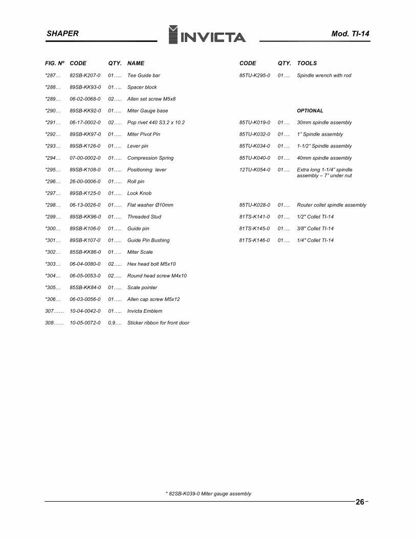
SHAPER Mod. TI-14
FIG. Nº CODE QTY. NAME CODE QTY. TOOLS
*287… 82SB-K207-0 01….. Tee Guide bar 85TU-K295-0 01…. Spindle wrench with rod
*288… 89SB-KK93-0 01….. Spacer block
*289… 06-02-0068-0 02….. Allen set screw M5x8
OPTIONAL *290… 89SB-KK92-0 01….. Miter Gauge base
*291… 06-17-0002-0 02….. Pop rivet 440 S3.2 x 10.2 85TU-K019-0 01…. 30mm spindle assembly
*292… 89SB-KK97-0 01….. Miter Pivot Pin 85TU-K032-0 01…. 1” Spindle assembly
*293… 89SB-K126-0 01….. Lever pin 85TU-K034-0 01…. 1-1/2” Spindle assembly
*294… 07-00-0002-0 01….. Compression Spring 85TU-K040-0 01…. 40mm spindle assembly
*295… 89SB-K108-0 01….. Positioning lever 12TU-K054-0 01…. Extra long 1-1/4” spindle assembly – 7” under nut
*296… 26-00-0006-0 01….. Roll pin
*297… 89SB-K125-0 01….. Lock Knob
*298… 06-13-0026-0 01….. Flat washer Ø10mm 85TU-K028-0 01…. Router collet spindle assembly
*299… 89SB-KK96-0 01….. Threaded Stud 81TS-K141-0 01…. 1/2" Collet TI-14
*300… 89SB-K106-0 01….. Guide pin 81TS-K145-0 01…. 3/8" Collet TI-14
*301… 89SB-K107-0 01….. Guide Pin Bushing 81TS-K146-0 01…. 1/4" Collet TI-14
*302… 85SB-KK86-0 01….. Miter Scale
*303… 06-04-0080-0 02….. Hex head bolt M5x10
*304… 06-05-0053-0 02….. Round head screw M4x10
*305… 85SB-KK84-0 01….. Scale pointer
*306… 06-03-0056-0 01….. Allen cap screw M5x12
307…… 10-04-0042-0 01….. Invicta Emblem
308…… 10-05-0072-0 0,9…. Sticker ribbon for front door
* 82SB-K039-0 Miter gauge assembly
26