Size-selected Metal Cluster Deposition on Oxide Surfaces ...
28/5/2014 Shaped Metal Deposition Processes - Springer
http://link.springer.com/referenceworkentry/10.1007/978-94-007-2739-7_808/fulltext.html 1/15
(1)
(2)
(3)
Richard B. Hetnarski
Encyclopedia of Thermal Stresses
10.1007/978-94-007-2739-7_808
© Springer Science+Business Media Dordrecht 2014
Shaped Metal Deposition Processes
Carlos Agelet de Saracibar 1, 2 , Andreas Lundbäck 3 , Michele Chiumenti 1, 2 and Miguel Cervera 1, 2
ETS Ingenieros de Caminos, Canales y Puertos, Universidad Politécnica de Cataluña, Barcelona Tech,Barcelona, Spain
International Center for Numerical Methods in Engineering (CIMNE), Barcelona, Spain
Department of Engineering Sciences and Mathematics, Mechanics of Solid Materials, Luleå Universityof Technology, Luleå, Sweden
Carlos Agelet de Saracibar (Corresponding author)Email: [email protected]
Andreas LundbäckEmail: [email protected]
Michele ChiumentiEmail: [email protected]
Miguel CerveraEmail: [email protected]
Without Abstract
Overview
The shaped metal deposition (SMD) process is a novel manufacturing technology which is similar to
the multi-pass welding used for building features such as lugs and flanges on components [1–7]. This
innovative technique is of great interest due to the possibility of employing standard welding
equipment without the need for extensive new investment [8, 9]. The numerical simulation of SMD
processes has been one of the research topics of great interest over the last years and requires a
fully coupled thermo-mechanical formulation, including phase-change phenomena defined in terms of
both latent heat release and shrinkage effects [1–6]. It is shown how computational welding
mechanics models can be used to model SMD for prediction of temperature evolution, transient, as
well as residual stresses and distortions due to the successive welding layers deposited. Material
behavior is characterized by a thermo-elasto-viscoplastic constitutive model coupled with a
metallurgical model [6]. Two different materials, nickel superalloy 718 [6] and titanium Ti-6Al-4 V
28/5/2014 Shaped Metal Deposition Processes - Springer
http://link.springer.com/referenceworkentry/10.1007/978-94-007-2739-7_808/fulltext.html 2/15
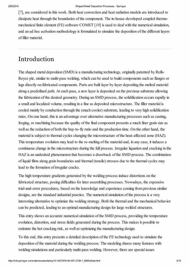
[7], are considered in this work. Both heat convection and heat radiation models are introduced to
dissipate heat through the boundaries of the component. The in-house-developed coupled thermo-
mechanical finite element (FE) software COMET [10] is used to deal with the numerical simulation,
and an ad hoc activation methodology is formulated to simulate the deposition of the different layers
of filler material.
Introduction
The shaped metal deposition (SMD) is a manufacturing technology, originally patented by Rolls-
Royce plc, similar to multi-pass welding, which can be used to build components such as flanges or
lugs directly on fabricated components. Parts are built layer by layer depositing the melted material
along a predefined path. At each pass, a new layer is deposited on the previous substrate allowing
the fabrication of the desired geometry. During an SMD process, the solidification occurs rapidly in
a small and localized volume, resulting in a fine as deposited microstructure. The filler material is
cooled mainly by conduction through the (much cooler) substrate, leading to very high solidification
rates. On one hand, this is an advantage over alternative manufacturing processes such as casting,
forging, or machining because the quality of the final component presents a much finer grain size as
well as the reduction of both the buy-to-fly ratio and the production time. On the other hand, the
material is subject to thermal cycles changing the microstructure of the heat-affected zone (HAZ).
This temperature evolution may lead to the re-melting of the material and, in any case, it induces a
continuous change in the microstructure during the full process. Irregular liquation and cracking in the
HAZ is an undesired phenomenon that becomes a drawback of the SMD process. The combination
of liquid films along grain boundaries and thermal (tensile) stresses due to the thermal cycles may
lead to the formation of irregular cracks.
The high temperature gradients generated by the welding process induce distortions on the
fabricated structure, posing difficulties for later assembling processes. Nowadays, the expensive
trial-and-error procedures, based on the knowledge and experience coming from previous similar
designs, are the standard industrial practice. The numerical simulation of the process is a very
interesting alternative to optimize the welding strategy. Both the thermal and the mechanical behavior
can be predicted, leading to an optimal manufacturing design for large welded structures.
This entry shows an accurate numerical simulation of the SMD process, providing the temperature
evolution, distortion, and stress fields generated during the process. This makes it possible to
estimate the hot cracking risk, as well as optimizing the manufacturing design.
To this end, this entry presents a detailed description of the FE technology used to simulate the
deposition of the material during the welding process. The modeling shares many features with
welding simulations and particularly multi-pass welding. However, there are special issues
28/5/2014 Shaped Metal Deposition Processes - Springer
http://link.springer.com/referenceworkentry/10.1007/978-94-007-2739-7_808/fulltext.html 3/15
(1)
(2)
(3)
concerning the modeling of the filler materials that build up the wanted features. The strategy
adopted consists on an element activation procedure, which allows switching on the elements
according to the welding path defined by the user. Also of importance is a constitutive model that is
able to describe the material behavior in all the temperature range of the process.
Coupled Thermo-Mechanical Model
The local system of partial differential equations governing the coupled thermo-mechanical initial
boundary value problem is defined by the linear momentum and energy balance equations, restricted
by the inequalities arising from the second law of the thermodynamics. This system must be
supplemented by suitable constitutive equations. Additionally, one must supply suitable prescribed
boundary and initial conditions.
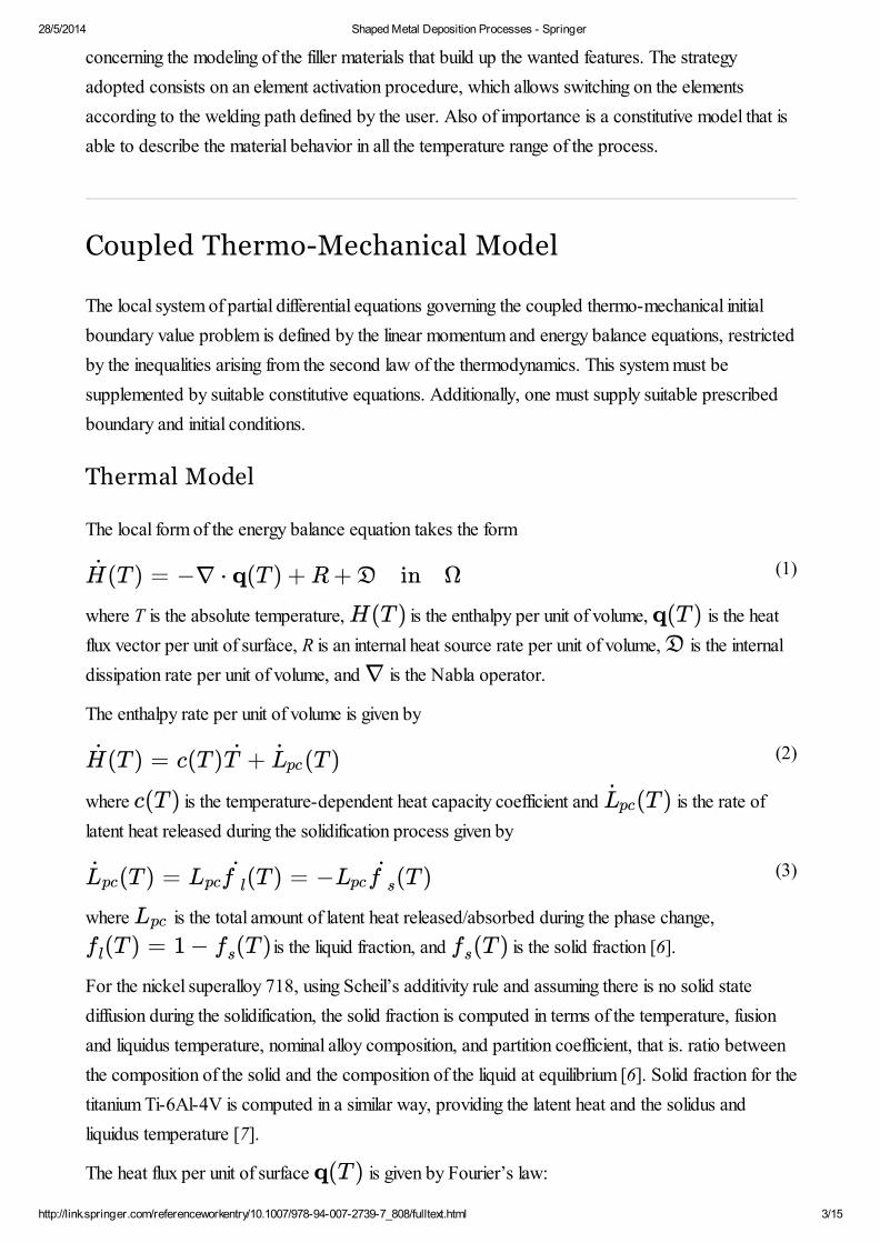
Thermal Model
The local form of the energy balance equation takes the form
where T is the absolute temperature, is the enthalpy per unit of volume, is the heat
flux vector per unit of surface, R is an internal heat source rate per unit of volume, is the internal
dissipation rate per unit of volume, and is the Nabla operator.
The enthalpy rate per unit of volume is given by
where is the temperature-dependent heat capacity coefficient and is the rate of
latent heat released during the solidification process given by
where is the total amount of latent heat released/absorbed during the phase change,
is the liquid fraction, and is the solid fraction [6].
For the nickel superalloy 718, using Scheil’s additivity rule and assuming there is no solid state
diffusion during the solidification, the solid fraction is computed in terms of the temperature, fusion
and liquidus temperature, nominal alloy composition, and partition coefficient, that is. ratio between
the composition of the solid and the composition of the liquid at equilibrium [6]. Solid fraction for the
titanium Ti-6Al-4V is computed in a similar way, providing the latent heat and the solidus and
liquidus temperature [7].
The heat flux per unit of surface is given by Fourier’s law:
(T ) = −∇ ⋅ q(T ) + R + D in ΩH
H(T ) q(T )D
∇
(T ) = c(T ) + (T )H T Lpc
c(T ) (T )Lpc
(T ) = (T ) = − (T )Lpc Lpcf l Lpc f s
Lpc
(T ) = 1 − (T )fl fs (T )fs
q(T )
28/5/2014 Shaped Metal Deposition Processes - Springer
http://link.springer.com/referenceworkentry/10.1007/978-94-007-2739-7_808/fulltext.html 4/15
(4)
(5)
(6)
(7)
where is the temperature-dependent thermal conductivity parameter.
The internal heat source rate per unit of volume plays a key role in the numerical simulation of SMD
processes, and different models have been proposed in the literature. Here, the internal heat source
rate per unit of volume is given by [6]
where V is the arc voltage, I is the welding current, is the volume of the filler material melted
by the feeding system during the current time step, and is the welding efficiency parameter. Thus,
we assume constant heat distribution over the filler material. Use of heat source models with, for
example, a Gaussian distribution will require a much finer finite element mesh than presently possible
to use for large 3D models of SMD.
For the numerical simulation of SMD processes, the thermo-mechanical dissipation rate per unit of
volume can be neglected in comparison with the large heat inputs from the weld source. Heat loss
by radiation, important at high temperatures in the HAZ, is computed using the Stefan-Boltzmann.
This effect can be accounted for by modifying the efficiency parameter of the heat source without a
significant loss of accuracy in the simulation. Heat dissipated by convection can be computed using
Newton’s law [6].
Mechanical Model
The local form of the linear momentum balance equation, assuming quasi-static conditions, takes the
form
where is the Cauchy stress tensor, is the vector of displacements, and is the vector
of body forces per unit of volume. The Cauchy stress tensor can conveniently be split into
where is the deviatoric part of the Cauchy stress tensor, p is the pressure, viewed as an
independent variable, and is the second-order unit tensor. This is practical in case of deviatoric
plasticity where the pressure is a pure thermo-elastic update. However, this split is necessary if a
mixed displacement-pressure finite element is used [6, 11–13]. This approach was used for the alloy
718 SMD case. A corresponding displacement formulation with underintegration of the volumetric
strain was used for the Ti6-4 SMD case. Both approaches remove the risk for locking due to the
plastic incompressibility condition [6, 11–13]. The governing equations for the mechanical problem,
given by the local mixed form of the linear momentum balance equation and the pressure constitutive
equation, take the form
q(T ) = −k(T )∇T
k(T )
R = ηV I
Vfeed
Vfeed
η
∇ ⋅ σ(u, T ) + f = 0 in Ω
σ(u, T ) u f
σ(u, T , p) = s(u, T ) + p1
s(u, T )1

28/5/2014 Shaped Metal Deposition Processes - Springer
http://link.springer.com/referenceworkentry/10.1007/978-94-007-2739-7_808/fulltext.html 5/15
(8)
(9)
(10)
(11)
(12)
where is the temperature-dependent bulk modulus and is the volumetric thermal
deformation which takes into account the thermal shrinkage during the phase change, from the
liquidus temperature to the solidus temperature , and the thermal contraction during the
cooling process, from solidus temperature to room temperature, and is defined as
where is the temperature-dependent mass density, is the temperature-dependent
secant thermal expansion coefficient, see entry Welding Stresses, is the initial temperature, the
temperature at which no thermal strains exist, and is the reference temperature, the
temperature used for a secant-based definition of the thermal expansion coefficient.
The deviatoric part of the constitutive equation for alloy 718 is given by
where is the temperature-dependent shear modulus, denotes the deviatoric
operator, denotes the symmetric gradient operator, and is the plastic strain.
Here, an associative rate-dependent J2 thermo-plastic model with isotropic hardening is considered,
and the yield function is given by [6]
where q is the isotropic hardening parameter in the stress space and is the
temperature-dependent radius of the von Mises yield surface given by
where is the temperature-dependent initial yield stress.
Note that for the liquid state, that is, , the solid fraction is zero, the volumetric thermal
deformation given by (9) is zero, and the radius of the von Mises yield surface given by (12) goes to
zero, yielding an incompressible rate-dependent rigid-plastic behavior characterized by
and a Norton-Hoff law arising from the plastic flow rule [6].
in∇ ⋅ s(u, T) + ∇p + f = 0
∇ ⋅ u − (T ) − p = 0eT
(T )fs
K(T )
⎫⎭⎬⎪⎪ Ω
K(T ) (T )eT
Tl Ts
(T ) =eT
⎧
⎩⎨⎪⎪⎪⎪⎪⎪⎪⎪⎪⎪⎪⎪⎪⎪⎪⎪⎪⎪
+ 3[α(T )(T − )ρ( ) − ρ( )Ts T l
ρ( )Ts
Tref
−α( )( − )] if T ≤T0 T0 Tref Ts
0 if ≤ TT l
if ≤ T ≤ρ(T ) − ρ( )T l
ρ( )Ts
Ts Tl
ρ(T ) α(T )T0
Tref
s(u, T ) = 2 dev( u − (u, T))G(T )(T )fs
∇ ep
G(T ) dev(⋅)(⋅)∇ (u, T)ep
ϕ(s, q, T ) = ∥s∥ − (q, T )RVM
(q, T )RVM
(q, T ) = (T ) ( (T ) − q)RVM fs
23
−−√ σ0
(T )σ0
T ≥ Tl
∇ ⋅ u = 0
28/5/2014 Shaped Metal Deposition Processes - Springer
http://link.springer.com/referenceworkentry/10.1007/978-94-007-2739-7_808/fulltext.html 6/15
Prediction of the hot cracking phenomena is a difficult task from a computational point of view [14].
Here, for the nickel superalloy 718, a continuum damage model based on macroscopic quantities is
used [6, 15]. The objective of the hot cracking model is to prevent from an excessive (tensile) stress
level when the material, still partially liquid, contracts (shrinkage) but all the surrounding phase has
solidified. Further details about the damage-enhanced model to predict hot cracking can be found in
[6].
A physical-based plasticity model, as described in the entry “Constitutive Models, Physically Based
Models for Plasticity” is used to describe the plastic behavior of Ti6-4. It accounts for low
temperature and high temperature plasticity including stress relaxation due to recovery by glide and
climb of dislocations. It also accounts for the phase change that Ti6-4 is subject to during the
temperature cycles [12].
Finite Element Modeling of the SMD Process
The numerical simulation of an SMD process requires an element activation technology to
reproduce the deposition of the melted material along a prescribed path. Here, the so-called born-
dead elements technique has been used. This activation strategy classifies the elements defined in the
original mesh into active, inactive, and activated elements. The active elements, such as the elements
defining the base material, are computed and assembled into the global matrix. The inactive
elements, such as the entire discretized domain defining the welding path, have been generated, but
they are not assumed as part of the model and do not play any role in the computational model. At
each time step, a number of elements, defined as activated elements, are switched on according to
the deposition of the filler material. Only active and activated elements are assembled into the
solution model. At each time step of the simulation, the profile of the solution matrix, as well as the
number of equations, is changing according to the activation process [6]. The activation can with
advantage be performed independently in the thermal and mechanical solutions as discussed in the
entry “Repair Welding and Local Heat Treatment”.
It can be noted that the boundary of the computational domain is changing due to the activation
process, requiring a specific searching strategy to update the active surface at each time step of the
numerical simulation. This is important to be able to correctly apply boundary conditions, such as the
heat radiation and heat convection fluxes, according to the activation process [6].
SMD processes induce extremely high temperature gradients that can provoke unrealistic
temperature overshoots and undershoots in the numerical solution, especially if coarse meshes and
large time steps are used. This has been avoided in the alloy 718 SMD case using a nodal (Lobatto)
integration rule which stabilizes the solution introducing a small numerical diffusivity into the heat
conduction problem [6, 13, 16]. A lumped heat capacity matrix was used in the Ti6-4 SMD case,
28/5/2014 Shaped Metal Deposition Processes - Springer
http://link.springer.com/referenceworkentry/10.1007/978-94-007-2739-7_808/fulltext.html 7/15
which also results in that any overshoots or undershoots are avoided.
Computational Simulations
The computational model presented in the previous sections for the nickel superalloy 718 has been
implemented in CIMNE’s in-house-developed coupled thermo-mechanical FE software COMET
[10]. The Ti6-4 SMD case was solved using MSC.Marc combined with user routines for
generating the weld paths, heat input, and the addition of filler material [7].
Alloy 718 SMD Process
This 10-layer SMD test case is intended to assess the accuracy of the proposed model when a fully
coupled thermo-mechanical analysis is applied to predict the temperature evolution, distortions, and
residual stresses of the structure.
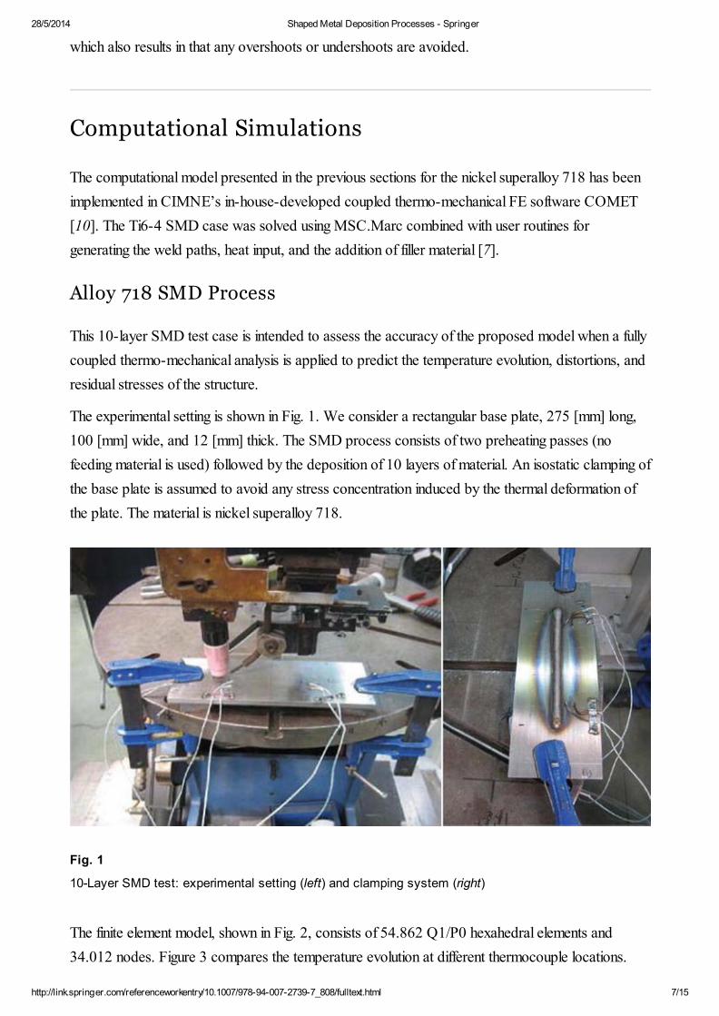
The experimental setting is shown in Fig. 1. We consider a rectangular base plate, 275 [mm] long,
100 [mm] wide, and 12 [mm] thick. The SMD process consists of two preheating passes (no
feeding material is used) followed by the deposition of 10 layers of material. An isostatic clamping of
the base plate is assumed to avoid any stress concentration induced by the thermal deformation of
the plate. The material is nickel superalloy 718.
Fig. 1
10-Layer SMD test: experimental setting (left) and clamping system (right)
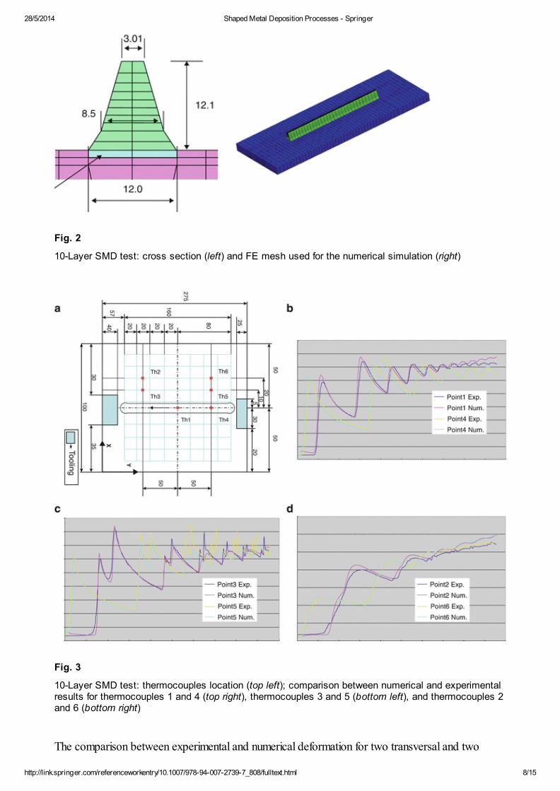
The finite element model, shown in Fig. 2, consists of 54.862 Q1/P0 hexahedral elements and
34.012 nodes. Figure 3 compares the temperature evolution at different thermocouple locations.
28/5/2014 Shaped Metal Deposition Processes - Springer
http://link.springer.com/referenceworkentry/10.1007/978-94-007-2739-7_808/fulltext.html 8/15
Fig. 2
10-Layer SMD test: cross section (left) and FE mesh used for the numerical simulation (right)
Fig. 3
10-Layer SMD test: thermocouples location (top left); comparison between numerical and experimentalresults for thermocouples 1 and 4 (top right), thermocouples 3 and 5 (bottom left), and thermocouples 2and 6 (bottom right)
The comparison between experimental and numerical deformation for two transversal and two
28/5/2014 Shaped Metal Deposition Processes - Springer
http://link.springer.com/referenceworkentry/10.1007/978-94-007-2739-7_808/fulltext.html 9/15
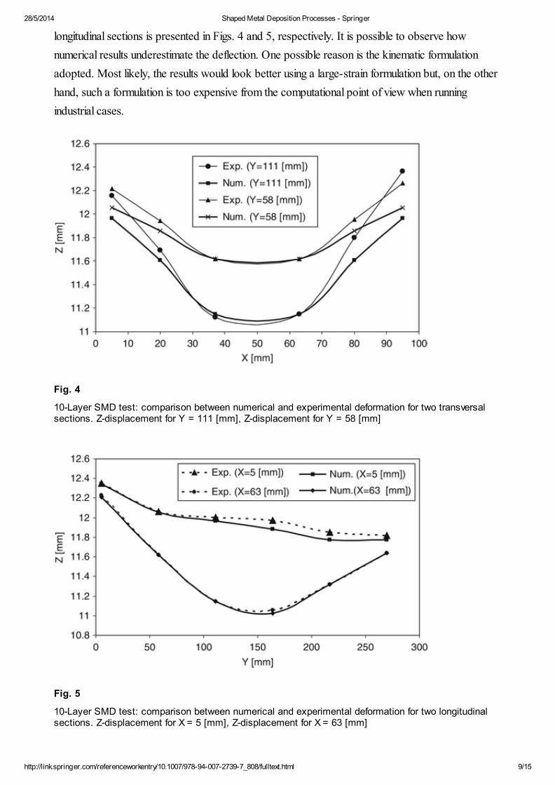
longitudinal sections is presented in Figs. 4 and 5, respectively. It is possible to observe how
numerical results underestimate the deflection. One possible reason is the kinematic formulation
adopted. Most likely, the results would look better using a large-strain formulation but, on the other
hand, such a formulation is too expensive from the computational point of view when running
industrial cases.
Fig. 4
10-Layer SMD test: comparison between numerical and experimental deformation for two transversalsections. Z-displacement for Y = 111 [mm], Z-displacement for Y = 58 [mm]
Fig. 5
10-Layer SMD test: comparison between numerical and experimental deformation for two longitudinalsections. Z-displacement for X = 5 [mm], Z-displacement for X = 63 [mm]
28/5/2014 Shaped Metal Deposition Processes - Springer
http://link.springer.com/referenceworkentry/10.1007/978-94-007-2739-7_808/fulltext.html 10/15
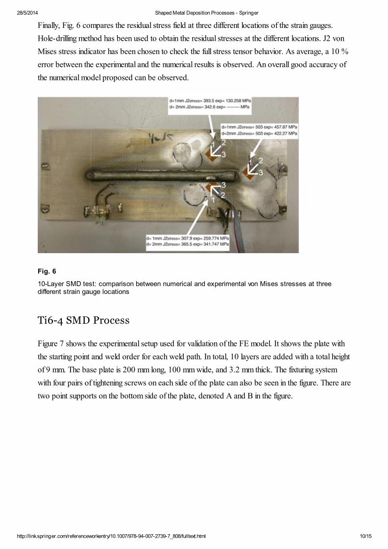
Finally, Fig. 6 compares the residual stress field at three different locations of the strain gauges.
Hole-drilling method has been used to obtain the residual stresses at the different locations. J2 von
Mises stress indicator has been chosen to check the full stress tensor behavior. As average, a 10 %
error between the experimental and the numerical results is observed. An overall good accuracy of
the numerical model proposed can be observed.
Fig. 6
10-Layer SMD test: comparison between numerical and experimental von Mises stresses at threedifferent strain gauge locations
Ti6-4 SMD Process
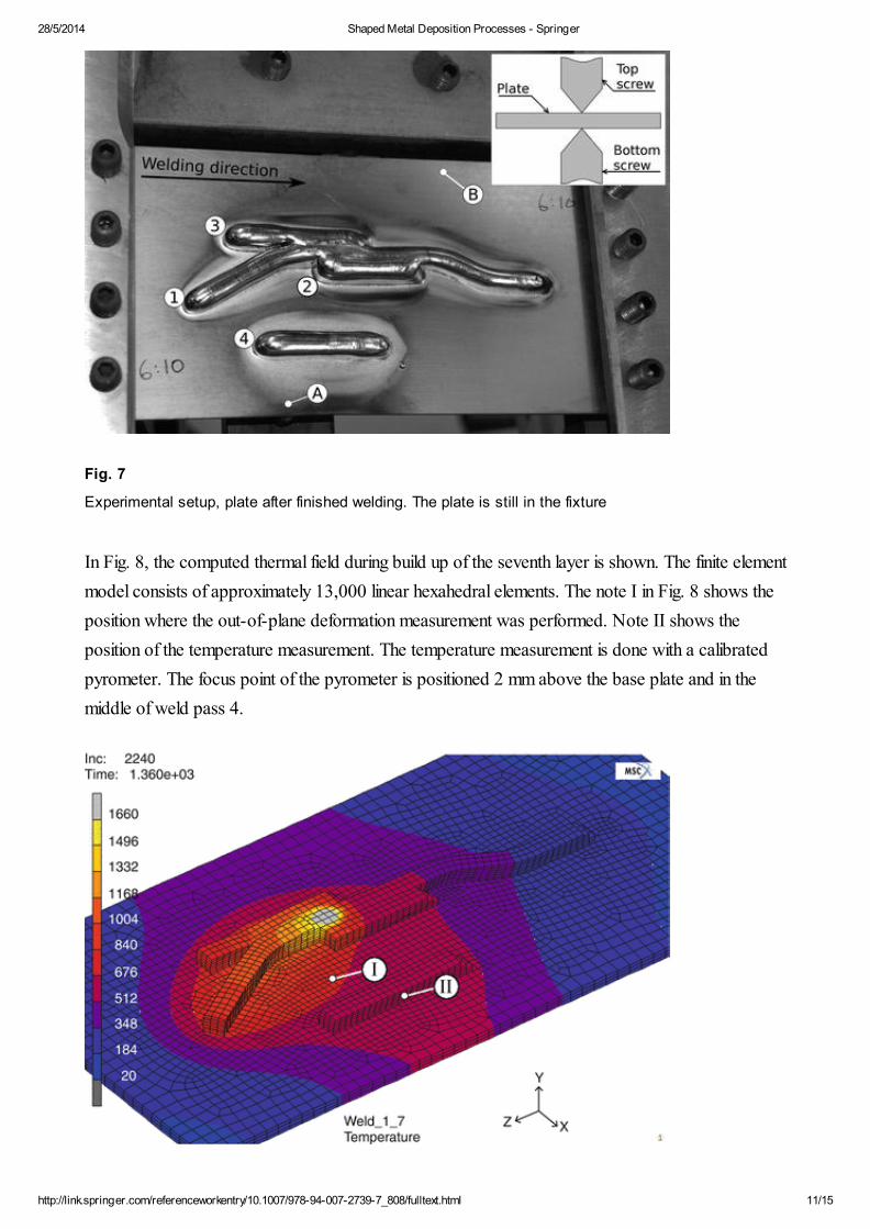
Figure 7 shows the experimental setup used for validation of the FE model. It shows the plate with
the starting point and weld order for each weld path. In total, 10 layers are added with a total height
of 9 mm. The base plate is 200 mm long, 100 mm wide, and 3.2 mm thick. The fixturing system
with four pairs of tightening screws on each side of the plate can also be seen in the figure. There are
two point supports on the bottom side of the plate, denoted A and B in the figure.
28/5/2014 Shaped Metal Deposition Processes - Springer
http://link.springer.com/referenceworkentry/10.1007/978-94-007-2739-7_808/fulltext.html 11/15
Fig. 7
Experimental setup, plate after finished welding. The plate is still in the fixture
In Fig. 8, the computed thermal field during build up of the seventh layer is shown. The finite element
model consists of approximately 13,000 linear hexahedral elements. The note I in Fig. 8 shows the
position where the out-of-plane deformation measurement was performed. Note II shows the
position of the temperature measurement. The temperature measurement is done with a calibrated
pyrometer. The focus point of the pyrometer is positioned 2 mm above the base plate and in the
middle of weld pass 4.
28/5/2014 Shaped Metal Deposition Processes - Springer
http://link.springer.com/referenceworkentry/10.1007/978-94-007-2739-7_808/fulltext.html 12/15
Fig. 8
Computed temperature field during the build up of the seventh layer
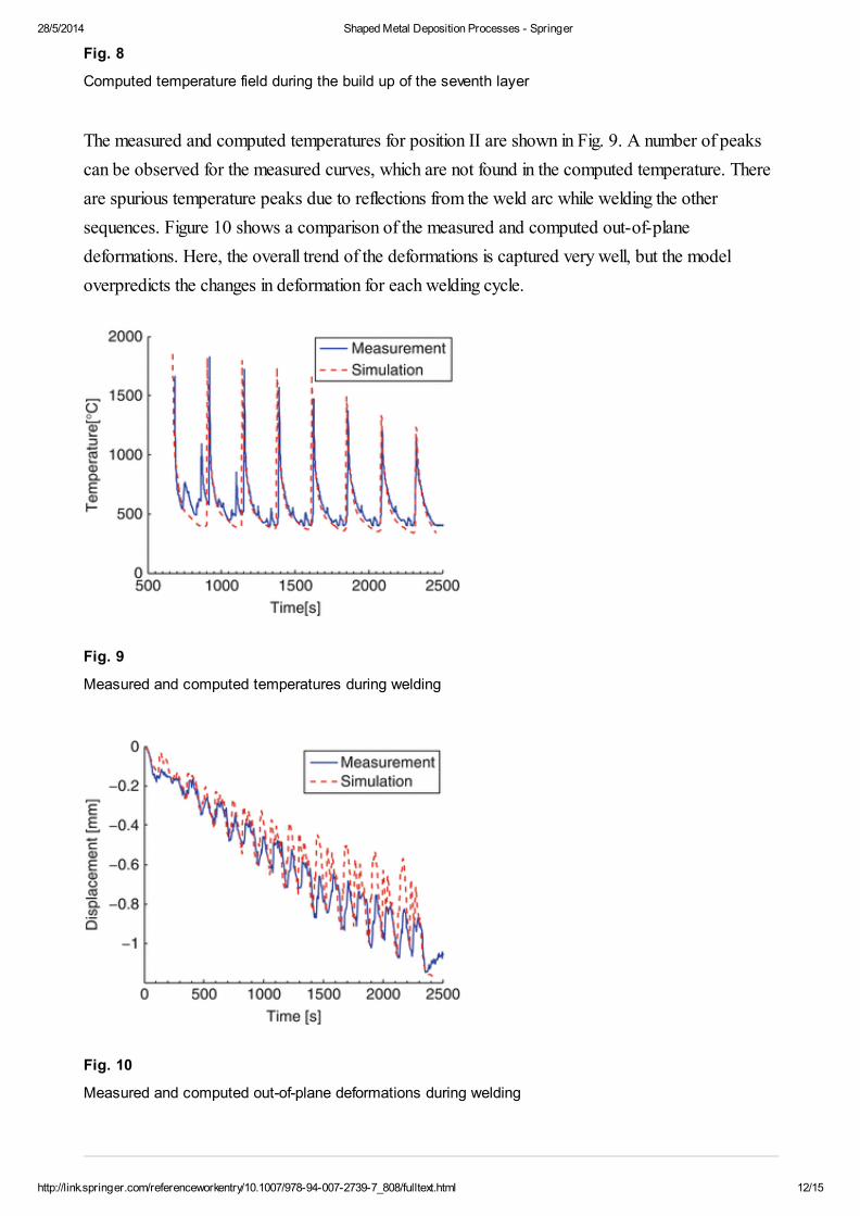
The measured and computed temperatures for position II are shown in Fig. 9. A number of peaks
can be observed for the measured curves, which are not found in the computed temperature. There
are spurious temperature peaks due to reflections from the weld arc while welding the other
sequences. Figure 10 shows a comparison of the measured and computed out-of-plane
deformations. Here, the overall trend of the deformations is captured very well, but the model
overpredicts the changes in deformation for each welding cycle.
Fig. 9
Measured and computed temperatures during welding
Fig. 10
Measured and computed out-of-plane deformations during welding
28/5/2014 Shaped Metal Deposition Processes - Springer
http://link.springer.com/referenceworkentry/10.1007/978-94-007-2739-7_808/fulltext.html 13/15
1.
2.
3.
4.
5.
6.
Future Development
Two strands have been identified as particularly important for the future development of modeling of
SMD. One is the development of constitutive and microstructural models and especially the coupling
between these. This is of particular interest in modeling of SMD as a large portion of the material is
subjected to multiple heating and cooling cycles. Another area that needs to be assessed is the
prediction of the shape of the filler material. As the main focus with SMD is to reduce the amount of
scrap, predicting the final shape of the added material is of great importance.
Cross-References
Computational Welding Mechanics
References
Lindgren L-E, Runnemalm H, Näsström M (1999) Simulation of multipass welding of a thick
plate. Int J Num Meths Eng 44:1301–1316
MATH
Lobitz DW, Mc Clure JD, Nickell RE (1977) Residual stresses and distorsions in multi pass
welding. In: Numerical modelling of manufacturing processes. Proceedings of the ASME WAM,
PVP-PB-25, pp 1–18
Lindgren L-E (2001) Finite element modelling of welding. Part 1: increased complexity. J
Therm Stress 24:141–192
Lindgren L-E (2001) Finite element modelling of welding. Part 2: improved material modeling. J
Therm Stress 24:195–231
Lindgren L-E (2001) Finite element modelling of welding. Part 3: efficiency and integration. J
Therm Stress 24:305–334
Chiumenti M, Cervera M, Salmi A, Agelet de Saracibar C, Dialami N, Matsui K (2010) Finite
element modeling of multi-pass welding and shaped metal deposition processes. Comput Meth Appl
Mech Eng 199:2343–2359
MATH
28/5/2014 Shaped Metal Deposition Processes - Springer
http://link.springer.com/referenceworkentry/10.1007/978-94-007-2739-7_808/fulltext.html 14/15
7.
8.
9.
10.
11.
12.
13.
14.
15.
16.
Lundbäck A, Lindgren L-E (2011) Modelling of metal deposition. Finite Elem Anal Des
47:1169–1177
Clark D, Bache MR, Whittaker MT (2008) Shaped metal deposition of a nickel alloy for aero
engine applications. J Mater Process Technol 203(1–3):439–448
Baufeld B, Van der Biest O, Gault R, Ridgway K (2011) Manufacturing Ti–6Al–4V
components by shaped metal deposition: microstructure and mechanical properties. In: IOP
conference series: materials science and engineering 26, 012001 doi:10.1088/1757-
899X/26/1/012001
Cervera M, Agelet de Saracibar C, Chiumenti M (2002) COMET – A coupled mechanical
and thermal analysis code. Data input manual. Version 5.0. Technical Report IT-308, CIMNE
Chiumenti M, Agelet de Saracibar C, Cervera M (2008) On the numerical modelling of the
thermo-mechanical contact for metal casting analysis. J Heat Transf 130:1–10
Babu B (2008) Physically based model for plasticity and creep of Ti-6Al-4V. Division of
Material Mechanics, Luleå University of Technology, Luleå
Agelet de Saracibar C, Cervera M, Chiumenti M (1999) On the formulation of coupled
thermoplastic problems with phase-change. Int J Plasticity 15:1–34
MATH
Hunzinker O, Dye D, Roberts SM, Reed RC (1999) A coupled approach for the prediction
of solidification cracking during the welding of superalloys. In: Proceedigs of the conference on
numerical analysis of weldability, Graz-Seggau, Austria
Lindgren L-E (2007) Computational welding mechanics: thermo-mechanical and
microstructural simulations. CRC Press, Boca Raton
Cervera M, Agelet de Saracibar C, Chiumenti M (1999) Thermomechanical analysis of
industrial solidification processes. Int J Num Meths Eng 46:1575–1591
MATH
Over 8.5 million scientific documents at your fingertips
© Springer, Part of Springer Science+Business Media

28/5/2014 Shaped Metal Deposition Processes - Springer
http://link.springer.com/referenceworkentry/10.1007/978-94-007-2739-7_808/fulltext.html 15/15