SHAPE Project Airinnova: Automation of High Fidelity … · SHAPE Project Airinnova: Automation of...
10
(*) Corresponding author: [email protected] Available online at www.prace-ri.eu Partnership for Advanced Computing in Europe SHAPE Project Airinnova: Automation of High Fidelity CFD Analysis in Aerodynamic Design Mengmeng Zhang a* , Jing Gong b , Michaela Barth b , Lilit Axner b a Airinnova AB, SE-182 48, Sweden b PDC Center for High Performance Computing, KTH Royal Institute of Technology, SE-100 44, Sweden Abstract Airinnova is a start-up company with a key competency in the automation of high fidelity computational fluid dynamics (CFD) analysis. The goal of this SHAPE project, a collaboration with the PDC Center for High Performance Computing at the KTH Royal Institute of Technology (KTH-PDC), was to develop automated procedures for carrying out CFD analysis in the field of aerodynamic optimization and design. The project is a significant step towards automation of the core processes that ordinarily would require specialist skills, such as creation of the simulation mesh, thus assisting a broader sphere of engineers to design aircraft in more efficient and simpler ways. 1. Introduction Airinnova AB is a start-up company that provides and develops advanced computational technology solutions for cutting edge aircraft preliminary design, computational aerodynamics, and multi-disciplinary optimization. High fidelity CFD analysis is a major tool for modern aircraft design and optimization, and the computational capability is a limiting factor. High fidelity CFD requires special skills in mesh generation and executing the analysis code, which constrains the use of the CFD analysis to a limited number of people who already have those skills. Airinnova is pursuing ways of performing CFD analysis automatically. This is being done by developing an automated procedure to carry out Reynolds-averaged Navier-Stokes (RANS) based CFD analysis, taking a watertight aircraft geometry defined by a Computer-Aided Design (CAD) file, or the emerging CPACS standard [1], as the starting point. Figure 1 illustrates the flow of data for automating CFD that Airinnova provides. It starts from a watertight geometry (left), and then the mesh is automatically generated (middle) for CFD analysis with selected turbulent models (right).
Transcript of SHAPE Project Airinnova: Automation of High Fidelity … · SHAPE Project Airinnova: Automation of...
(*) Corresponding author: [email protected]
Available online at www.prace-ri.eu
Partnership for Advanced Computing in Europe
SHAPE Project Airinnova: Automation of High Fidelity CFD
Analysis in Aerodynamic Design
Mengmeng Zhanga*, Jing Gongb, Michaela Barthb, Lilit Axnerb
aAirinnova AB, SE-182 48, Sweden bPDC Center for High Performance Computing, KTH Royal Institute of Technology, SE-100 44, Sweden
Abstract
Airinnova is a start-up company with a key competency in the automation of high fidelity computational fluid dynamics (CFD) analysis. The goal of this SHAPE project, a collaboration with the PDC Center for High Performance Computing at the KTH Royal Institute of Technology (KTH-PDC), was to develop automated procedures for carrying out CFD analysis in the field of aerodynamic optimization and design. The project is a significant step towards automation of the core processes that ordinarily would require specialist skills, such as creation of the simulation mesh, thus assisting a broader sphere of engineers to design aircraft in more efficient and simpler ways.
1. Introduction
Airinnova AB is a start-up company that provides and develops advanced computational technology solutions for cutting edge aircraft preliminary design, computational aerodynamics, and multi-disciplinary optimization. High fidelity CFD analysis is a major tool for modern aircraft design and optimization, and the computational capability is a limiting factor. High fidelity CFD requires special skills in mesh generation and executing the analysis code, which constrains the use of the CFD analysis to a limited number of people who already have those skills. Airinnova is pursuing ways of performing CFD analysis automatically. This is being done by developing an automated procedure to carry out Reynolds-averaged Navier-Stokes (RANS) based CFD analysis, taking a watertight aircraft geometry defined by a Computer-Aided Design (CAD) file, or the emerging CPACS standard [1], as the starting point. Figure 1 illustrates the flow of data for automating CFD that Airinnova provides. It starts from a watertight geometry (left), and then the mesh is automatically generated (middle) for CFD analysis with selected turbulent models (right).
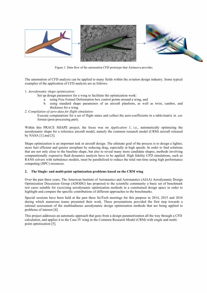
Figure 1: Data flow of the automation CFD prototype that Airinnova provides
The automation of CFD analysis can be applied to many fields within the aviation design industry. Some typical examples of the application of CFD analysis are as follows: 1. Aerodynamic shape optimization:
Set up design parameters for a wing to facilitate the optimization work: a. using Free Formal Deformation box control points around a wing, and b. using standard shape parameters of an aircraft planform, as well as twist, camber, and
thickness for a wing. 2. Compilation of aero-data for flight simulation:
Execute computations for a set of flight states and collect the aero-coefficients in a table/matrix in .csv format (post-processing part).
Within this PRACE SHAPE project, the focus was on Application 1, i.e., automatically optimizing the aerodynamic shape for a reference aircraft model, namely the common research model (CRM) aircraft released by NASA [1] and [3]. Shape optimization is an important task in aircraft design. The ultimate goal of the process is to design a lighter, more fuel efficient and quieter aeroplane by reducing drag, especially at high speeds. In order to find solutions that are not only close to the baseline shape, but also to reveal many more candidate shapes, methods involving computationally expensive fluid dynamics analysis have to be applied. High fidelity CFD simulations, such as RANS solvers with turbulence models, must be parallelized to reduce the total run-time using high performance computing (HPC) resources. 2. The Single- and multi-point optimization problems based on the CRM wing
Over the past three years, The American Institute of Aeronautics and Astronautics (AIAA) Aerodynamic Design Optimization Discussion Group (ADODG) has proposed to the scientific community a basic set of benchmark test cases suitable for exercising aerodynamic optimization methods in a constrained design space in order to highlight and compare the specific contributions of different approaches to the benchmarks.
Special sessions have been held at the past three SciTech meetings for this purpose in 2014, 2015 and 2016 during which numerous teams presented their work. These presentations provided the first step towards a rational assessment of the multitudinous aerodynamic design optimization methods that are being applied to problems of interest [4].
This project addresses an automatic approach that goes from a design parametrization all the way through a CFD calculation, and applies it to the Case IV wing in the Common Research Model (CRM) with single and multi-point optimization [5].
3
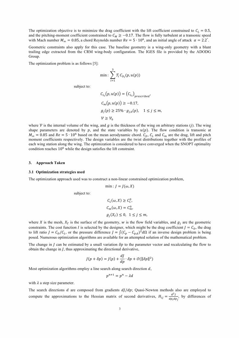
The optimization objective is to minimize the drag coefficient with the lift coefficient constrained to 𝐶! = 0.5, and the pitching-moment coefficient constrained to 𝐶! ≥ −0.17. The flow is fully turbulent at a transonic speed with Mach number 𝑀! = 0.85, a chord Reynolds number 𝑅𝑒 = 5 ∙ 10!, and an initial angle of attack 𝛼 = 2.2°.
Geometric constraints also apply for this case. The baseline geometry is a wing-only geometry with a blunt trailing edge extracted from the CRM wing-body configuration. The IGES file is provided by the ADODG Group.
The optimization problem is as follows [5]:
min : 𝒯!
!
!!!
𝐶!!(𝑝, 𝑢(𝑝))
subject to:
𝐶!! 𝑝, 𝑢 𝑝 = 𝐶!! !"#$%"&'#(,
𝐶! 𝑝, 𝑢 𝑝 ≥ −0.17,
𝑔! 𝑝 ≥ 25% ∙ 𝑔!,! 𝑝 , 1 ≤ 𝑗 ≤ 𝑚,
𝒱 ≥ 𝒱!
where 𝒱 is the internal volume of the wing, and 𝑔 is the thickness of the wing on arbitrary stations (𝑗). The wing shape parameters are denoted by 𝑝, and the state variables by 𝑢(𝑝). The flow condition is transonic at 𝑀! = 0.85 and 𝑅𝑒 = 5 ∙ 10! based on the mean aerodynamic chord. 𝐶!, 𝐶! and 𝐶! are the drag, lift and pitch moment coefficients respectively. The design variables are the twist distributions together with the profiles of each wing station along the wing. The optimization is considered to have converged when the SNOPT optimality condition reaches 10! while the design satisfies the lift constraint.
3. Approach Taken
3.1 Optimization strategies used
The optimization approach used was to construct a non-linear constrained optimization problem,
min : 𝐽 = 𝐽(𝜔,𝑋)
subject to:
𝐶! 𝜔,𝑋 ≥ 𝐶!!,
𝐶! 𝜔,𝑋 = 𝐶!! ,
𝑔! 𝑋! ≤ 0, 1 ≤ 𝑗 ≤ 𝑚,
where 𝑋 is the mesh, 𝑋! is the surface of the geometry, 𝑤 is the flow field variables, and 𝑔! are the geometric constraints. The cost function 𝐼 is selected by the designer, which might be the drag coefficient 𝐽 = 𝐶!, the drag to lift ratio 𝐽 = 𝐶!/𝐶!, or the pressure difference 𝐽 = (𝐶! − 𝐶!,!)!𝑑Ω if an inverse design problem is being posed. Numerous optimization algorithms are available for an attempted solution of the mathematical problem.
The change in 𝐽 can be estimated by a small variation 𝛿𝑝 to the parameter vector and recalculating the flow to obtain the change in 𝐽, thus approximating the directional derivative,
𝐽 𝑝 + 𝛿𝑝 = 𝐽 𝑝 +𝑑𝐽𝑑𝑝
∙ 𝛿𝑝 + 𝒪( 𝛿𝑝 !)
Most optimization algorithms employ a line search along search direction 𝑑,
𝑝!!! = 𝑝! − 𝜆𝑑
with 𝜆 a step size parameter.
The search directions 𝑑 are composed from gradients 𝑑𝐽/𝑑𝑝; Quasi-Newton methods also are employed to compute the approximations to the Hessian matrix of second derivatives, 𝐻!" =
!!!!"!!"!
, by differences of
4
gradients in an updating scheme. As a result, computation of the gradients dominates the computational cost for high-dimensional parameter spaces.
The gradient can be calculated by simply applying the finite-difference method [6],
Δ 𝐽 𝑝 =𝐽 𝑝 + 𝛿𝑝 − 𝐽(𝑝)
𝛿𝑝
The finite difference method can also be used to find these sensitivities but it is in general significantly more expensive, requiring at least one additional flow solution per parameter. It works particularly well if the design parameter 𝑝 is of order 𝒪(10) since the re-meshing technique is fast and robust, even for generating RANS meshes [7]. The optimization can be speeded up by calculating the gradient using smart parallelization: all derivatives are computed at once, each one on its own cluster node. The computation time can thus be reduced to almost that of just an additional CFD simulation.
3.2 Automatic mesh generation
The mesh generation algorithm is written as
𝑀 𝑿,𝑿𝚪 = 0
and the surface parametrization algorithm 𝑆 is constrained by
𝑆 𝑿𝚪,𝒑 = 0
where 𝒑 are the design variables which determine the surface 𝑋!.
The mesh generators were investigated since the quality of meshes is one of most important issues for shape optimization design. Two different mesh generators, the commercial software Pointwise [8] as well as the in-house software SUMO (https://www.larosterna.com/sumo.html) developed by KTH, were used to create meshes on the same surface of geometry.
SUMO can be used for automatically generating Euler (tetrahedron) and RANS (pentahedron) meshes [9]. To generate the RANS mesh, pentagrow needs to be run before TetGen in batch mode by executing a configuration file with a list of user-defined parameters to set up the prismatic layers such as the first cell height, the total number of layers, the growth rate, and so forth.
3.3 The CFD solvers
Two CFD codes for shape optimization have been investigated in the project. One of the CFD solvers, SU2 is a computational analysis and design package that has been developed to solve multi-physics analysis and optimization tasks using unstructured mesh topologies [10] - [13]. The SU2 optimization package can be easily used just by typing one command line, provided that the cost function, constraints, the control points of the Free Form Deformation (FFD) Bézier box for wing parametrization and the other numerical parameters are all correctly set up in the configuration file. The other CFD solver is a Swedish in-house code, which is a general CFD finite volume method solver.
3.4 The automatic optimization framework
The automatic optimization framework is built based on loosely coupling different computational modules. CFD solvers and geometric handling packages are complex and the commercial packages have data structures and application program interfaces that are proprietary, with documentation unavailable to users. However, every package has input and output files which are necessarily well-documented. The computational modules can be coupled by monitor-type programs which understand the file formats and know how to read and write the files and how to translate between different parameterizations.
Figure 2 shows the process of a set of optimization scripts creating a SUMO configuration file with the geometry computed from the parameters. The grid is based on a surface grid generated by SUMO and then sent on to pentagrow which makes a prismatic-layer based volume grid, with the output being a mesh-file for CFD solvers. The CFD solver(s) compute the flow solution and return quantities of interest (such as pressure fields, forces, and moments) as files. These are read by the optimization scripts, which then evaluate the objective and

5
constraint functions, compute updated values of the parameters, and repeat the sequence. The gradients that are needed by the optimization algorithm are computed by finite differences. The loose coupling makes it possible to easily distribute the requisite tasks on cluster computers.
Figure 2: Automatic Optimization Approach using SUMO
4. Results
4.1 Mesh generation
The baseline CRM wing-body configuration was investigated, starting from the same surface mesh and gridding generated by both SUMO and Pointwise. The mesh settings for the two generators are shown in Table 1, to make sure that the SUMO-G01 mesh and Pointwise-mesh share the same settings (namely the most similar meshes obtained). Note that the mesh generated by Pointwise is the half configuration with a symmetric plane while SUMO can only generate a full configuration within the domain.
MESH-GEN #POINTS #TETRAHEDRON #PYRAMID #PRISM
POINTWISE 4,601,010 4,185,417 49,413 7,618,103
SUMO-G00 10,296,466 5,507,393 - 18,635,680
SUM0-G01 10,548,294 7,108,594 - 18,635,680
Table 1: The comparison for the mesh generated by Pointwise and SUMO
6
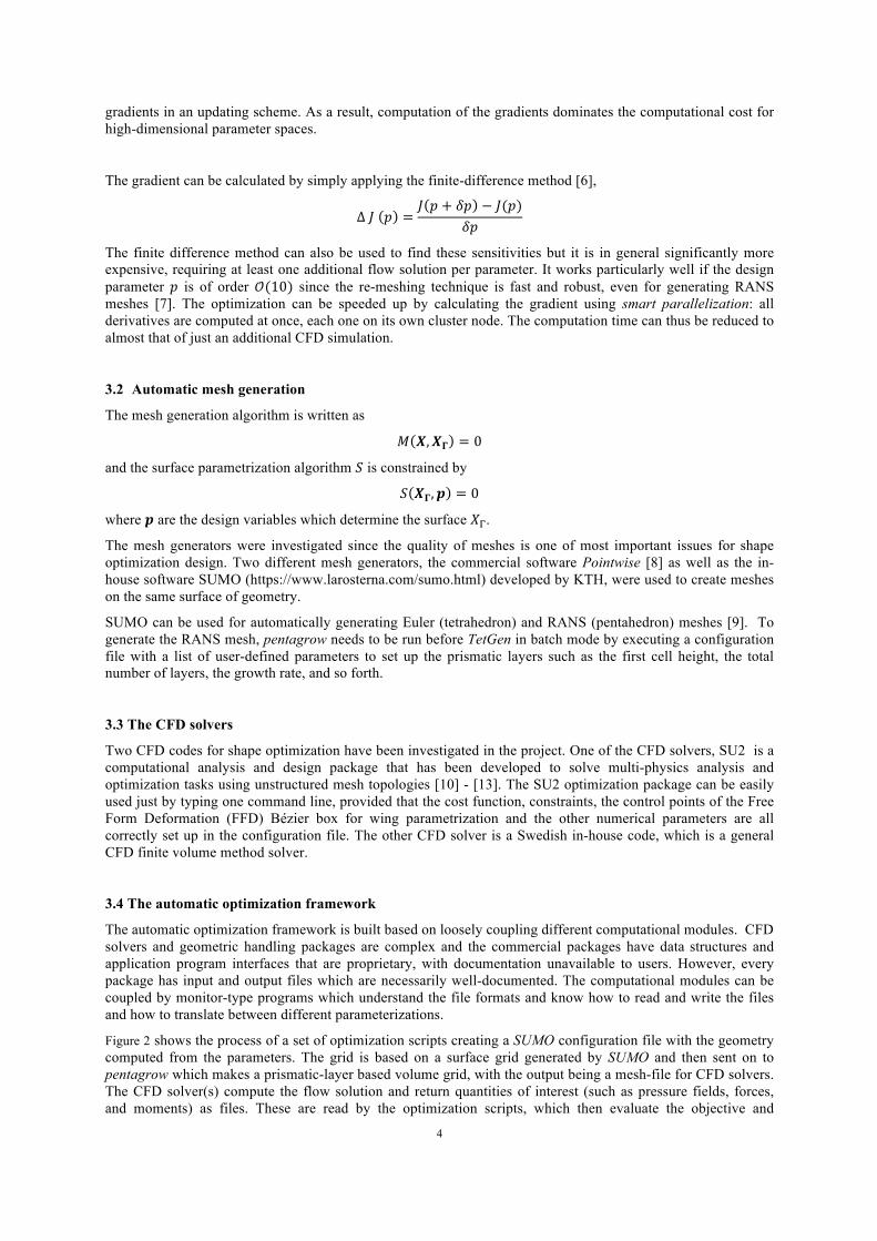
Figure 3: Grid comparison of tetrahedral resolution for CRM wing-body configure, Pointwise-grid vs. SUMO-grid
As the quality of meshes directly affects the computational results, the results of lift coefficient 𝐶!, drag coefficient 𝐶!, and pitching moment 𝐶! were compared with different meshes using SU2 for the CFD SA model. The results are shown in Table 2. These coefficients are very close to each other, which illustrates the validity of the meshes.
MESH 𝑪𝑳 𝑪𝑫 𝑪𝑴
POINTWISE 0.500426 0.0299926 -0.0417215
SUMO-G00 0.488478 0.0307847 -0.0485054
SUMO-G01 0.486335 0.0297765 -0.0449285
Table 2: Validity for the results of lift, drag and pitching coefficients using SU2 for the CFD SA model
4.2 Performance results
The simulations were performed on the Cray XC40 system Beskow [14] at PDC, KTH, and MareNostrum [15] at BSC, Spain. Beskow is based on Intel Haswell processors and Cray Aries interconnect technology. It consists of 1676 compute nodes, each of which consists of 32 Intel Xeon E5-2698v3 cores. MareNostrum is a supercomputer based on Intel SandyBridge processors. It has 36 racks dedicated to calculations. These racks have a total of 48,448 Intel SandyBridge cores with a frequency of 2.6 GHz and 94.625 TB of total memory. In total, each rack has a total of 1,344 cores and 2,688 GB of memory.
The scalability tests were carried out on Beskow and MareNostrum. Figure 4(a) shows the performance results for the mesh SUMO-G01 consisting of 10.5 M points on Beskow. The benchmarking tests ran for 10,000 iterations. The strong scaling performance measured in total execution time in seconds is presented in this figure. The parallel efficiency 𝜂(%) at maximum used cores is defined as:
𝜂 % =𝑇!"# ∙ 𝑁!"#𝑇!"# ∙ 𝑁!"#
∙ 100
where 𝑇!"# is the total execution time for the minimum number of cores 𝑁!"#, while 𝑇!"# is the total execution time using the maximum number of cores 𝑁!"#.
A parallel efficiency 𝜂 = 57.1% can be achieved for up to 960 cores compared with 80 cores. Figure 4 (b) shows the performance results for a mesh of baseline with 10 million mesh points on MareNostrum. A parallel efficiency 𝜂 = 54.8% of can be obtained for 1024 cores compared with 32 cores.

7
(a) Beskow (b) MareNostrum
Figure 4: Performance results on Beskow and MareNostrum
4.3 Thrust computation on the complete configuration
A more realistic design was made by shifting towards a complete configuration by adding pylons and nacelles. Such a mesh was made by Pointwise with the same gridding density as SUMO-G01 and the computation was performed on Beskow. Figure 6 shows the downstream turbulent kinetic energy, under the flow condition at Mach = 0.8, angle of attack 𝛼 = 0°, Reynolds number Re = 10! (of the reference chord), with the net thrust 𝑇 = 11 kN per engine.
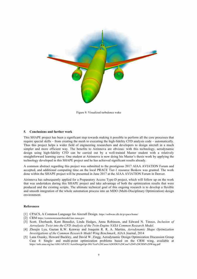
The figures below show the computation results for the complete configuration in different aspects. Figure 5 shows the flow streamlines around the aircraft configuration; note that the flow is accelerated by the engine to provide thrust. Figure 6 is the downstream flow visualization – here the flow around the rear of the engine contains more turbulent kinetic energy as the thrust itself is adding energy (and the momentum). Figure 7 and Figure 8 show the jet flow visualization and turbulence wake respectively. The surface of the complete aircraft configuration is contoured by the Pressure Coefficient (CP). Note that the shock is formed around the 75% chord of the main wing, as well as the nacelle inlet. It results in wave drag, which is one of the most important drag components that is aimed to reduce.
Figure 5: Visualized flow streamlines around the complete aircraft configuration

8
Figure 6: Visualized downstream flow contoured by turbulent kinetic energy
Figure 7: Visualized tip vortices and the jet flow
9
Figure 8: Visualized turbulence wake
5. Conclusions and further work
This SHAPE project has been a significant step towards making it possible to perform all the core processes that require special skills – from creating the mesh to executing the high-fidelity CFD analysis code – automatically. Thus this project helps a wider field of engineering researchers and developers to design aircraft in a much simpler and more efficient way. The benefits to Airinnova are obvious: with this technology, aerodynamic design using high-fidelity CFD can be carried out by a well-trained Master student with a relatively straightforward learning curve. One student at Airinnova is now doing his Master’s thesis work by applying the technology developed in this SHAPE project and he has achieved significant results already.
A common abstract regarding this project was submitted to the prestigious 2017 AIAA AVIATION Forum and accepted, and additional computing time on the local PRACE Tier-1 resource Beskow was granted. The work done within the SHAPE project will be presented in June 2017 at the AIAA AVIATION Forum in Denver.
Airinnova has subsequently applied for a Preparatory Access Type-D project, which will follow up on the work that was undertaken during this SHAPE project and take advantage of both the optimization results that were produced and the existing scripts. The ultimate technical goal of this ongoing research is to develop a flexible and smooth integration of the whole automation process into an MDO (Multi-Disciplinary Optimization) design environment.
References
[1] CPACS, A Common Language for Aircraft Design. https://software.dlr.de/p/cpacs/home/ [2] CRM https://commonresearchmodel.larc.nasa.gov [3] Scott. Eberhardt, Kent Benedict, Linda Hedges, Anna Robinson, and Edward N. Tinoco, Inclusion of
Aeroelastic Twist into the CFD Analysis of the Twin-Engine NASA Common Research Model. [4] Zhoujie Lyu, Gaetan K.W. Kenway and Joaquim R. R. A. Martins, Aerodynamic Shape Optimization
Investigations of the Common Research Model Wing Benchmark, AIAA Journal, 2014 [5] Lana Osusky, Howard Buckley, and David W. Zingg, Aerodynamic Design Optimization Discussion Group
Case 4: Single- and multi-point optimization problems based on the CRM wing, available at https://info.aiaa.org/tac/ASG/APATC/AeroDesignOpt-DG/Test%20Cases/ADODG%20Case%204%20CRM%20Wing.pdf
10
[6] Igor Griva, Stephen G. Nash, Ariela Sofer, Linear and Nonlinear Optimization, Second Edition, 2009, ISBN: 978-0-898716-61-0.
[7] Mengmeng Zhang, Contributions to Variable Fidelity MDO Framework for Collaborative and Integrated Aircraft Design, Doctoral Thesis, Royal Institute of Technology KTH, Stockholm, Sweden, 2015.
[8] Pointwise Mesh generation software for CFD, http://www.pointwise.com/ [9] Tomac M., Towards Automated CFD for Engineering Methods in Aircraft Design, Stockholm, Sweden,
Royal Institute of Technology, KTH, 2014, ISSN 1651-7660. [10] SU2 the open-source CFD code, http://su2.stanford.edu [11] Francisco Palacios, Thomas D. Economon, Andrew D. Wendorff, and Juan J. Alonso, Large-scale aircraft
design using SU2, AIAA SciTech 5-9 January 2015, Kissimmee, Florida, 53rd AIAA Aerospace Sciences Meeting.
[12] Thomas D. Economon, Dheevatsa Mudigereb, Gaurav Bansalc, Alexander Heinecked, Francisco Palaciose, Jongsoo Parkd, Mikhail Smelyanskiyd, Juan J. Alonsoa, Pradeep Dubeyd, Performance optimizations for scalable implicit RANS calculations with SU2, Computers & Fluids, Vol.129(28), 2016, pp. 146—158
[13] Thomas D. Economon, Francisco Palacios, Sean R. Copeland, Trent W. Lukaczyk, and Juan J. Alonso. SU2: An Open-Source Suite for Multiphysics Simulation and Design, AIAA Journal, Vol. 54, No. 3 (2016), pp. 828-846.
[14] Beskow, https://www.pdc.kth.se/resources/computers/beskow [15] MareNostrum, https://www.bsc.es/innovation-and-services/supercomputers-and-facilities/marenostrum
Acknowledgements
This work was financially supported by the PRACE project funded in part by the EU’s Horizon 2020 research and innovation programme (2014-2020) under grant agreement 653838. The work was done using the PRACE research infrastructure Tier-0 resource MareNostrum at BSC, Spain, and the Tier-1 resource Beskow at KTH-PDC, Sweden. The support for the technical work via the PRACE SHAPE programme is also gratefully acknowledged.


![Multi-fidelity optimization of super-cavitating hydrofoils · flows around any 2D hydrofoils shape [24] and successively extended to consider three dimensional geometries. The parametric](https://static.fdocuments.net/doc/165x107/5b3141537f8b9a81728b9207/multi-fidelity-optimization-of-super-cavitating-hydrofoils-flows-around-any.jpg)