Shadow Puppetry Using the Kinect - Semantic Scholar Individual Project Shadow Puppetry Using the...
71
COM3600 Individual Project Shadow Puppetry Using the Kinect Author: Benjamin M. Carr Supervisor: Dr. Guy J. Brown 6 th May 2014 This report is submitted in partial fulfilment of the requirement for the degree of Master of Computing in Computer Science by Benjamin M. Carr.
Transcript of Shadow Puppetry Using the Kinect - Semantic Scholar Individual Project Shadow Puppetry Using the...
COM3600 Individual Project
Shadow Puppetry Using the Kinect
Author: Benjamin M. Carr
Supervisor: Dr. Guy J. Brown
6th May 2014
This report is submitted in partial fulfilment of the requirement for the degree
of Master of Computing in Computer Science by Benjamin M. Carr.

i
Declaration
All sentences or passages quoted in this report from other people's work have
been specifically acknowledged by clear cross-referencing to author, work and
page(s). Any illustrations which are not the work of the author of this report
have been used with the explicit permission of the originator and are
specifically acknowledged. I understand that failure to do this amounts to
plagiarism and will be considered grounds for failure in this project and the
degree examination as a whole.
Name: Benjamin M. Carr
Date: 6th May 2014
Signature:
ii
Abstract
Shadow puppetry is a form of storytelling where the characters are made from
the shadows cast by puppets. The goal of this project is to build a real-time
shadow puppet storytelling application using the Microsoft Kinect sensor. Its
depth sensing ability is the perfect tool for tracking users and allowing them to
control puppets onscreen, just by moving their body. The project is developed
in the C++ programming language and uses the Cinder library for image
processing.
The system includes various image processing techniques to achieve a real-
time, depth-based blur effect that is both efficient and visually appealing. It
also includes a robust gesture recognition system based on the dynamic time
warping algorithm to allow users to interact with the system and to create
engaging and varied stories. These stories can be recorded and saved to file for
later playback, or exported as video files.
iii
Acknowledgements
I would like to thank my supervisor Guy Brown for allowing me to take on this
project and for all his guidance throughout. I would also like to thank my
family and friends for their constant support.
iv
Contents
Declaration ...................................................................................................... i
Abstract ......................................................................................................... ii
Acknowledgements ........................................................................................ iii
Contents ........................................................................................................ iv
Chapter 1: Introduction ................................................................................. 1
Chapter 2: Literature Review ........................................................................ 2
2.1 Shadow Puppetry .............................................................................. 2
2.1.1 Wayang Kulit ............................................................................ 3
2.2 Kinect (C++) ................................................................................... 4
2.2.1 History ....................................................................................... 5
2.2.2 Technology ................................................................................ 6
2.2.3 Drivers ....................................................................................... 7
2.2.4 Skeleton Tracking ..................................................................... 8
2.3 Image Processing............................................................................. 10
2.3.1 Programming Libraries ........................................................... 10
2.3.2 Blurring ................................................................................... 11
2.3.3 Gaussian Blurring ................................................................... 12
2.3.4 Alternative Blur Techniques ................................................... 13
2.4 Gesture Recognition ........................................................................ 14
2.4.1 Hidden Markov Models ........................................................... 14
2.4.2 Dynamic Time Warping .......................................................... 15
Chapter 3: Requirements and Analysis ....................................................... 17
3.1 System Requirements ...................................................................... 17
3.2 Analysis ........................................................................................... 19
3.2.1 Real-time Blurring .................................................................. 19
3.2.2 Recording Shadow Plays ......................................................... 20
3.2.3 Gesture Recognition ................................................................ 21
3.3 Testing and Evaluation .................................................................. 22
Chapter 4: Design ........................................................................................ 24
4.1 Methodology ................................................................................... 24
v
4.2 System Overview ............................................................................ 25
4.3 System Interaction .......................................................................... 28
4.4 Storytelling ...................................................................................... 30
Chapter 5: Implementation and Testing...................................................... 31
5.1 Implementation ............................................................................... 31
5.1.1 Programming Language and Framework ................................ 31
5.1.2 Rendering Shadow Puppets .................................................... 32
5.1.3 Real-time Blurring .................................................................. 35
5.1.4 Saving Stories .......................................................................... 37
5.1.5 Gesture Recognition ................................................................ 40
5.1.6 Other Features ........................................................................ 43
5.2 Testing ............................................................................................ 44
Chapter 6: Results and Discussion .............................................................. 45
6.1 User Feedback ................................................................................. 45
6.2 System Performance ....................................................................... 47
6.3 Gesture Recognition ........................................................................ 49
6.4 File Handling .................................................................................. 51
6.5 Video Exporting .............................................................................. 54
6.6 Requirements Evaluation ................................................................ 55
6.7 Further Work .................................................................................. 57
Chapter 7: Conclusions ................................................................................ 59
References .................................................................................................... 61
Table of Figures ........................................................................................... 65
1
Chapter 1: Introduction
Shadow puppetry is a form of storytelling where the characters are made from
the shadows cast by puppets. It originated in Southeast Asia and is particularly
popular on the Indonesian islands Java and Bali. A traditional shadow puppet
set consists of three components: a light source, a translucent screen and a set
of puppets in the shape of figurines and objects. These puppets are placed in
between the light source and the screen to create the shadows that the
audience see.
This project aims to bring traditional shadow puppetry into the digital age,
with the aid of the Kinect. The Kinect is a piece of hardware originally
developed as a peripheral for the Xbox 360 gaming console, but has since been
released as a developer tool for the PC. Its main feature is its ability to track
objects in three dimensions using its infrared depth sensing technology. For this
project, the Kinect Skeleton API will be used to track the user’s body
movements and translate them over to the onscreen puppet.
The system will be developed to allow users to control their own virtual
puppets in real-time. Using the position of various joints in the user’s body and
arms, the puppet will be able to imitate poses and actions that the user
performs as they move around. There will also be a series of image processing
effects including depth blurring as the user moves forwards and backwards.
However, performing real-time blurring is not an easy task and will require an
efficient algorithm to be feasible. Finally, a gesture recognition system will be
implemented to allow actions to be performed during stories, such as changing
puppets. All these features combined will allow users to record and playback
their own stories or export them as videos to share with friends. The final
product will be used as an entertainment application primarily aimed at
teenagers and students.
Chapter 2 of this document will explore existing literature on different
aspects of the system, and will help to explain the details of the system. It will
cover various elements of the Kinect including its skeleton tracking algorithm,
and how different gesture recognition techniques can be used. On top of this, it
will also cover image processing techniques such as real-time Gaussian blurring,
and how external frameworks and libraries can provide some of this
functionality. Chapter 3 will formally outline the requirements of the system
and explore methods of testing, while Chapter 4 will explain the final plan for
the system. Chapter 5 section explores the system in more detail followed by
chapter 6 which explores and evaluates the final system. Finally, chapter 7 will
summarise this report.
2
Chapter 2: Literature Review
The literature review provides background information on the project and
examines existing publications in the areas relating to the project. Each of
these areas provides core functionality to the system, and many have already
been implemented in similar systems in the past. Analysing these past systems
helps to identify different options for this project and weight up which will be
best for this particular system. It also highlights potential problems which may
be encountered during development, allowing for early contingency plans to be
made. This section aims to explore these relevant areas in more detail,
highlighting how they will be used in this project and what benefits they have
over alternative methods.
2.1 Shadow Puppetry
As mentioned earlier in the report, this project is based around simulating
shadow puppetry using the Kinect. Shadow puppetry (or shadow play) is a
form of storytelling where the characters and props are made from the shadows
cast by puppets. Traditional shadow play performances originated in Southeast
Asia where they are considered an ancient art, but have also spread to Western
countries.
A shadow puppet set consists of three components: a light source, a
translucent screen and a series of objects or puppets which are used to create
the shadows. These puppets are placed in between the light source and the
screen; the resulting shadows represent the characters and props used within
the story. The audience views the show from the other side of the screen and
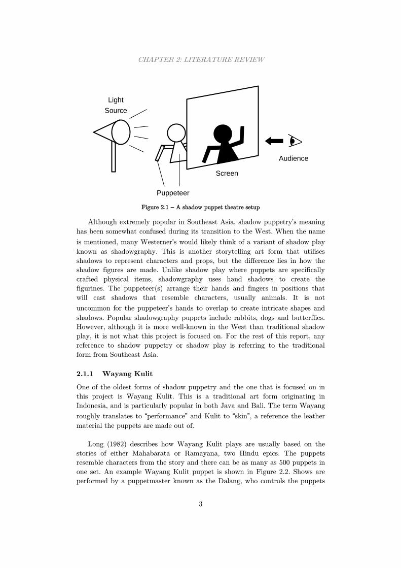
therefore will only see the shadow figurines being depicted. Figure 2.1 shows a
basic shadow puppet theatre setup. Traditional shadow puppet theatres would
have used alternative light sources such as an oil lamp.
CHAPTER 2: LITERATURE REVIEW
3
Figure 2.1 – A shadow puppet theatre setup
Although extremely popular in Southeast Asia, shadow puppetry’s meaning
has been somewhat confused during its transition to the West. When the name
is mentioned, many Westerner’s would likely think of a variant of shadow play
known as shadowgraphy. This is another storytelling art form that utilises
shadows to represent characters and props, but the difference lies in how the
shadow figures are made. Unlike shadow play where puppets are specifically
crafted physical items, shadowgraphy uses hand shadows to create the
figurines. The puppeteer(s) arrange their hands and fingers in positions that
will cast shadows that resemble characters, usually animals. It is not
uncommon for the puppeteer’s hands to overlap to create intricate shapes and
shadows. Popular shadowgraphy puppets include rabbits, dogs and butterflies.
However, although it is more well-known in the West than traditional shadow
play, it is not what this project is focused on. For the rest of this report, any
reference to shadow puppetry or shadow play is referring to the traditional
form from Southeast Asia.
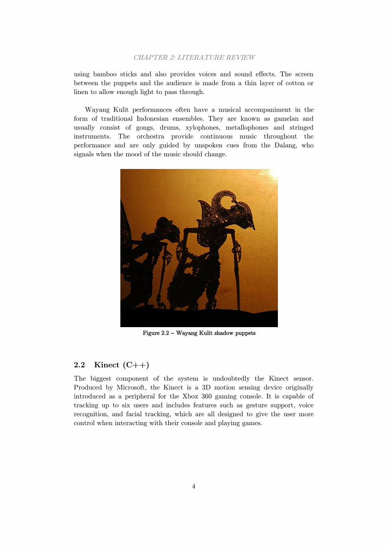
2.1.1 Wayang Kulit
One of the oldest forms of shadow puppetry and the one that is focused on in
this project is Wayang Kulit. This is a traditional art form originating in
Indonesia, and is particularly popular in both Java and Bali. The term Wayang
roughly translates to “performance” and Kulit to “skin”, a reference the leather
material the puppets are made out of.
Long (1982) describes how Wayang Kulit plays are usually based on the
stories of either Mahabarata or Ramayana, two Hindu epics. The puppets
resemble characters from the story and there can be as many as 500 puppets in
one set. An example Wayang Kulit puppet is shown in Figure 2.2. Shows are
performed by a puppetmaster known as the Dalang, who controls the puppets
Audience
Screen
Puppeteer
Light
Source
CHAPTER 2: LITERATURE REVIEW
4
using bamboo sticks and also provides voices and sound effects. The screen
between the puppets and the audience is made from a thin layer of cotton or
linen to allow enough light to pass through.
Wayang Kulit performances often have a musical accompaniment in the
form of traditional Indonesian ensembles. They are known as gamelan and
usually consist of gongs, drums, xylophones, metallophones and stringed
instruments. The orchestra provide continuous music throughout the
performance and are only guided by unspoken cues from the Dalang, who
signals when the mood of the music should change.
Figure 2.2 – Wayang Kulit shadow puppets
2.2 Kinect (C++)
The biggest component of the system is undoubtedly the Kinect sensor.
Produced by Microsoft, the Kinect is a 3D motion sensing device originally
introduced as a peripheral for the Xbox 360 gaming console. It is capable of
tracking up to six users and includes features such as gesture support, voice
recognition, and facial tracking, which are all designed to give the user more
control when interacting with their console and playing games.
CHAPTER 2: LITERATURE REVIEW
5
2.2.1 History
In the 2009 E31 event, Microsoft announced that it is working on a new
motion-sensing controller for the Xbox 360 gaming console, known then as
Project Natal. The announcement featured a demonstration of the racing game
Burnout Paradise being played with the new device. Unlike previous consoles,
the player controlled the vehicle by grabbing hold of an invisible ‘steering
wheel’ in the space above them, turning their hands to steer. This kind of
motion control was a completely new innovation, like nothing before it and
instantly gained a lot of excitement and coverage from the press.
As the Kinect grew in popularity, demand grew for the Kinect to be opened
up for public development. Microsoft responded to the demand in 2012 by
releasing the Kinect for Windows and the free Kinect SDK2, allowing
developers to create their own Kinect enabled applications. This was designed
to open up the possibilities of the Kinect for uses other than gaming, enabling
anyone with the device to access data from their device and build their own
systems in C++, C# or Visual Basic. The SDK has been through many
iterations and today (at version 1.8) offers skeletal tracking, facial recognition,
gesture recognition, background removal and even the ability to build up
complex 3D models of an environment scanned with the Kinect3.
Since the launch of the original Kinect, Microsoft has released their next
generation of gaming console and the Xbox 360’s replacement, the Xbox One.
At the same time, they also revised the Kinect which is sold with the new
console. The new Kinect contains an array of improvements over the old
version, including faster processing, greater accuracy and a higher resolution
camera. This revised device is currently only available for the new Xbox One
console, but Microsoft have confirmed that an updated Kinect for Windows
will be released in 2014 allowing developers to take advantage of the new
hardware in other applications. However, because the new Kinect is not yet
compatible with PC’s, this project will use the original Kinect.
PrimeSense, the company who provided the technology for the original
Kinect, have recently been acquired by the electronics company Apple. It is
rumoured that 3D sensing technology may also find its way into smartphones,
tablets and laptops in the near future, proving just how successful the original
Kinect has been.
1 Electronic Entertainment Expo 2 Software development kit 3 Using Kinect Fusion technology included in the SDK and compatible
hardware
CHAPTER 2: LITERATURE REVIEW
6
Similar games consoles have also attempted to create their own motion
sensing devices. The most notable example of this was the Nintendo Wii, which
was likely to have been inspiration for Kinect. This was released in 2006 and
unlike any console before it, featured a wireless remote controller. It uses
multiple accelerometers to determine its orientation and infrared technology to
track where the user is in 3D space. This was something completely new to the
gaming world and was received by the public extremely well, winning multiple
awards. Sony then released a similar device called PlayStation Move which also
utilises a webcam to capture the player’s movements.
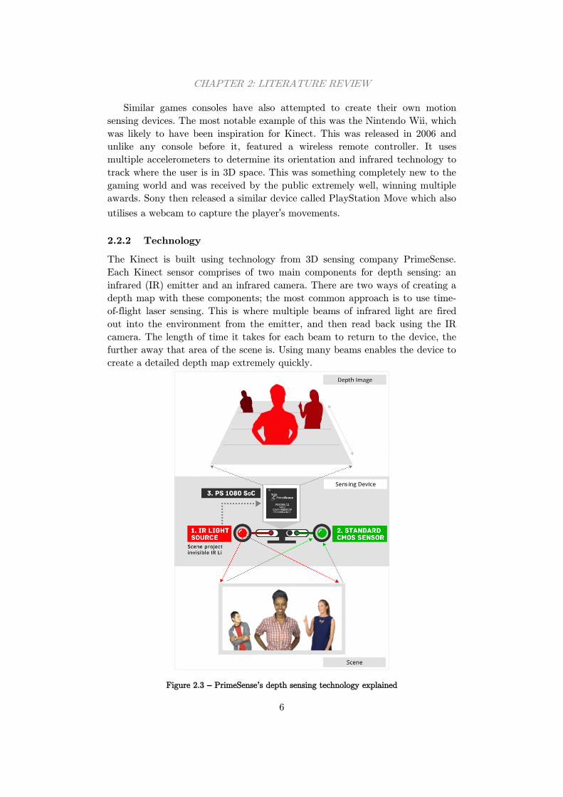
2.2.2 Technology
The Kinect is built using technology from 3D sensing company PrimeSense.
Each Kinect sensor comprises of two main components for depth sensing: an
infrared (IR) emitter and an infrared camera. There are two ways of creating a
depth map with these components; the most common approach is to use time-
of-flight laser sensing. This is where multiple beams of infrared light are fired
out into the environment from the emitter, and then read back using the IR
camera. The length of time it takes for each beam to return to the device, the
further away that area of the scene is. Using many beams enables the device to
create a detailed depth map extremely quickly.
Figure 2.3 – PrimeSense’s depth sensing technology explained
CHAPTER 2: LITERATURE REVIEW
7
However, the Kinect employs the second depth sensing method. Unlike
time-of-flight sensing, the Kinect emits coded patterns of light into the scene.
Depending on how far the light has to travel, or in other words how close the
objects are to the emitter, the light coding will become distorted. The amount
of distortion indicates the depth at that particular point in the scene. The IR
sensor then scans the scene and reads in each section of coded light and runs it
through PrimeSense’s Light Coding™ algorithms. This uses triangulation
between the sensor, emitter and coded light in the scene to calculate the actual
depth of each area, building up a full depth map of the environment from the
devices point of view.
The Kinect also features some interesting algorithms for detecting humans.
One feature the device includes is Kinect Identity which allows it to recognise
different users based on their appearance. Leyvand, et al. (2011) explains that
this is done using three attributes of the player: facial recognition, their clothes
and their height. Every time a user walks into view, these attributes are
identified and the system attempts to find a match against existing user
attributes. It creates a truth table of every attribute that matches and the
stored user that scores highest will be the identification used. If there are no
matches at all, the system will not identify the user.
This technique works well but is not without its challenges. For instance,
although a height will not change quickly, people will almost certainly change
their clothes each time they use the system. Also, facial recognition may fail if
the user pulls different facial expressions. To avoid this problem, the system
stores extra information about the user when they are identified such as the
lighting conditions and the time of day. It also builds up a dataset about the
user taking multiple snapshots to accommodate for different environment
conditions. Over time, this dataset will build until the user can be correctly
identified in almost any condition, whether the setting has changed or their
appearance changes.
2.2.3 Drivers
Microsoft provides a free SDK for any developer who wishes to build
applications for the Kinect. This was released in conjunction with the Kinect
for Windows version of the device, which is specifically aimed for PC based
development. Since its release, it has been updated and refined to include more
API’s1 and unlock more of the devices potential. These have included major
updates such as face tracking, background removal, seated skeleton tracking
and also Kinect Fusion which allows 3D models to be created by scanning
1 Application Programming Interface – defines how different software
components should communicate
CHAPTER 2: LITERATURE REVIEW
8
environments with the device. There have also been smaller additions such as
the accelerometer control, colour camera settings and infrared emitter API’s for
finer control of the components in the device, amongst general software
improvements.
The official SDK from Microsoft is designed to be used in three
programming languages: C++, C# and Visual Basic. While these are all
powerful languages, none of them allow multi-platform applications to be
developed; they must run on a PC. In 2010, a competition was posted requiring
contestants to develop an open-source driver for the Kinect. The winner of this
contest successfully produced a Kinect driver for Linux known as LibFreenect
with basic access to colour and depth camera information. This opened up the
possibility of using the Kinect on other platforms and with different
programming languages, essentially making it accessible to even more
developers.
Only a month after the competition ended, PrimeSense who supplied the
technology behind the Kinect announced that they were also developing their
own open-source drivers. These were released in an SDK called OpenNI which
is a joint effort between PrimeSense and other developers, and is available for
Windows, Linux and Mac. PrimeSense also went one step further, releasing a
motion tracking middleware called NITE which brings some of the official SDK
algorithms to these other platforms, including skeleton tracking, hand tracking,
gesture recognition and background removal.
For this project, all of the development will be done on a Windows machine
in C++. Therefore, there would be no benefit in using the open-source drivers
and SDK from PrimeSense. Instead, the project will use the official SDK from
Microsoft which not only provide more functionality, but also will be more
reliable and efficient for the application. This is especially important when
dealing with real-time applications such as this one.
This project will also use the Cinder library, which will be explored in more
detail in Section 2.3.1. Cinder applications are slightly different to a traditional
C++ application and import ‘blocks’ of code to enable more functionality.
There is a Cinder block called KinectSDK which allows the official SDK to be
used within Cinder applications such as this one, which is what will be
implemented in this project. Again, this will be covered in more detail later on
in the report.
2.2.4 Skeleton Tracking
One of the most important features of the Kinect is its ability to track users in
real-time. This is handled using the Skeleton API included in the official Kinect
SDK but before this can happen, the user must be identified and extracted
CHAPTER 2: LITERATURE REVIEW
9
from the camera image. Zeng (2012) explains how Microsoft use an efficient
algorithm to achieve this in real-time. Each part of the user’s body is split into
segments and represented using joints, where the complete set of joints forms a
skeleton. To segment a user’s body, each pixel is classified using a set of
training data. This data consists of example human shapes in various poses to
give a full representation of the human body in all forms. The classifier itself
uses hundreds of thousands of training images to find a possible match, using
randomness to lower computational costs.
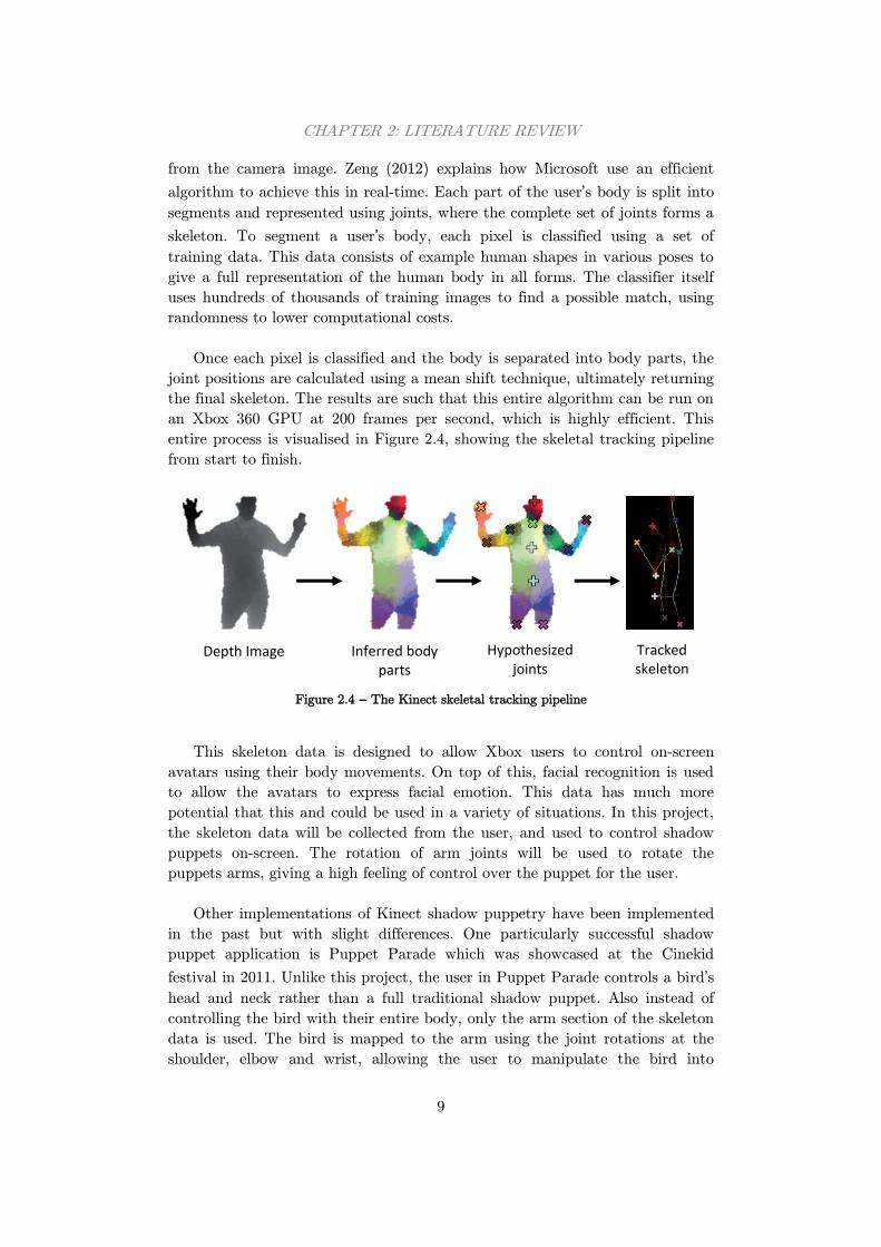
Once each pixel is classified and the body is separated into body parts, the
joint positions are calculated using a mean shift technique, ultimately returning
the final skeleton. The results are such that this entire algorithm can be run on
an Xbox 360 GPU at 200 frames per second, which is highly efficient. This
entire process is visualised in Figure 2.4, showing the skeletal tracking pipeline
from start to finish.
Figure 2.4 – The Kinect skeletal tracking pipeline
This skeleton data is designed to allow Xbox users to control on-screen
avatars using their body movements. On top of this, facial recognition is used
to allow the avatars to express facial emotion. This data has much more
potential that this and could be used in a variety of situations. In this project,
the skeleton data will be collected from the user, and used to control shadow
puppets on-screen. The rotation of arm joints will be used to rotate the
puppets arms, giving a high feeling of control over the puppet for the user.
Other implementations of Kinect shadow puppetry have been implemented
in the past but with slight differences. One particularly successful shadow
puppet application is Puppet Parade which was showcased at the Cinekid
festival in 2011. Unlike this project, the user in Puppet Parade controls a bird’s
head and neck rather than a full traditional shadow puppet. Also instead of
controlling the bird with their entire body, only the arm section of the skeleton
data is used. The bird is mapped to the arm using the joint rotations at the
shoulder, elbow and wrist, allowing the user to manipulate the bird into
Depth Image Inferred body parts
Hypothesized joints
Tracked skeleton
CHAPTER 2: LITERATURE REVIEW
10
different positions. The bird puppet also has the ability to “squawk” by opening
its mouth, controlled by the user opening their hand. The plan for this project
is to take this one step further and utilise the whole body movements to
control a traditional Indonesian shadow puppet.
2.3 Image Processing
An important technique used for many applications is image processing. This is
the process of taking an image or video frame and modifying certain
parameters of the image in order to change its appearance. Image processing is
a common technique used in computer graphics which can be used to create
many effects for a wide variety of purposes. Examples of effects created using
image processing include greyscale, sharpening, blurring, noise reduction,
contrast modifications, white balance and colourisation. One or more of these
techniques can be used to enhance images in a variety of ways.
2.3.1 Programming Libraries
C++, which is the programming language that will be used in this project,
allows applications to be built for Windows machines. However, it is not a
language designed for computer graphics purposes, and especially not for image
processing. Therefore, additional libraries are required to create a shadow
puppet application which utilises advanced computer graphics. This project will
include the Cinder library, which provides many methods and implementations
that are required for creating applications such as audio, video, networking,
geometry and most importantly, graphics and image processing.
Cinder utilises OpenGL, an industry standard API that allows the
rendering of 2D and 3D graphics by communicating directly with the GPU
(Graphics Processing Unit). This allows hardware-acceleration to be achieved
which boosts the performance of rendering by running computation on the
GPU hardware rather than in the software. It also provides methods for
multiple platforms and languages, not only computer based but also mobile
based devices and even on web browsers. For this project, OpenGL will be used
to render the 3D puppet scene and to interact with the Kinect’s 3D skeleton
data.
Although Cinder will provide all the relevant graphics libraries required,
there are alternative libraries that can be used. Another C++ library which
provides similar functionality is openFrameworks. Similar to Cinder, this
includes many libraries used for graphics and image processing. However, the
main difference between the two is the libraries that are included in each.
Cinder is dependent on many libraries that are included in the operating
system, whereas openFrameworks uses more open-source libraries. The
advantages of open-source libraries are that they provide more control when
CHAPTER 2: LITERATURE REVIEW
11
developing applications, but what they lack is the reliability and robustness of
operating system libraries. When working with real-time 3D graphics, it is very
important for the application to be robust and responsive which explains why
Cinder has been chosen for this particular project.
A similar library aimed towards Java applications is Processing. This
contains much of the same functionality as Cinder and openFrameworks, but
targets cross-platform compatibility. The library itself uses its own variant of
Java and comes bundled with a full IDE1 for easier development. It also
integrates OpenGL like the other two and supports 2D and 3D graphics, with
its main aim to teach users basic programming using a visual context. However
because it is based on Java, it will lack the performance of C++ applications
and is therefore not as well suited to real-time application utilising the Kinect.
2.3.2 Blurring
Image processing can be used to produce many effects, but one particularly
interesting effect is blurring. This effect is commonly used to produce depth of
field, bloom and motion blurs. However, what may seem like a simple process
can involve a great deal of computation to achieve a visually pleasing result.
Blurring, in addition to many other effects, utilises a convolution matrix or
kernel which is simply a fixed size matrix of numbers. The matrix is used to
modify each pixel in an image based on the pixels in its surrounding area,
known as a neighbourhood. The number in the centre of the matrix represents
the pixel being analysed, and the rest of the numbers define the neighbouring
pixel’s influences.
Kernels are used for each and every pixel in the image which can be a
computationally expensive task. The kernel must be moved around the entire
image, and this is done using a technique known as discrete convolution.
Press, et al. (1989) provide the definition of 2D discrete convolution which can
be seen in Equation 2.1, where represents the kernel, represents the image
and and represent the neighbourhood of pixels surrounding the pixel
defined by ( ). Convolution uses the star operator ( ) with the kernel, the
image and the current pixel to apply the kernel to that pixel. This equation is
calculated for every pixel in the image. When the kernel is faced with an edge
of the image and pixel data is not available, there are a few techniques which
can be used. The most common is to extend the edge pixel outwards to supply
the missing data, but another method is to tile the image and use data from
the opposite edge.
1 Integrated Development Environment
CHAPTER 2: LITERATURE REVIEW
12
( )( ) ∑ ∑ ( ) ( )
Equation 2.1 – 2D Discrete Convolution
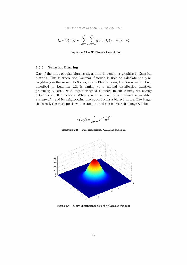
2.3.3 Gaussian Blurring
One of the most popular blurring algorithms in computer graphics is Gaussian
blurring. This is where the Gaussian function is used to calculate the pixel
weightings in the kernel. As Sonka, et al. (1999) explain, the Gaussian function,
described in Equation 2.2, is similar to a normal distribution function,
producing a kernel with higher weighed numbers in the centre, descending
outwards in all directions. When run on a pixel, this produces a weighted
average of it and its neighbouring pixels, producing a blurred image. The bigger
the kernel, the more pixels will be sampled and the blurrier the image will be.
( )
Equation 2.2 – Two dimensional Gaussian function
Figure 2.5 – A two dimensional plot of a Gaussian function
CHAPTER 2: LITERATURE REVIEW
13
2.3.4 Alternative Blur Techniques
One of the major problems with a Gaussian blur is that it is computationally
expensive and takes a long time to produce a result, especially for large images
and kernels. However, there are techniques which can be used to reduce the
amount of computation required. A common technique as described by Horn
(1986) is to use a two-pass, one-dimensional Gaussian blur, using convolution.
This involves a one-dimensional kernel which is applied twice for the same
image; once to blur the image horizontally and once to blur vertically. This is
made possible due to the fact that Gaussian filters are separable, meaning that
multiple smaller filters can be applied to achieve the same effect as one large
filter. Using two passes is essentially the same as creating a two-dimensional
kernel and using that on the image, like a traditional Gaussian blur. The final
result is the same as a two-dimensional Gaussian blur but with much less
computation required.
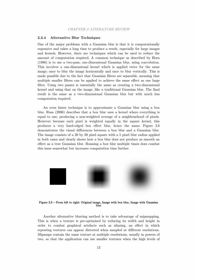
An even faster technique is to approximate a Gaussian blur using a box
blur. Russ (2006) describes that a box blur uses a kernel where everything is
equal to one, producing a non-weighted average of a neighbourhood of pixels.
However because each pixel is weighted equally in the square kernel, this
produces a very hard-edged box effect blur, hence the name. Figure 2.6
demonstrates the visual differences between a box blur and a Gaussian blur.
The image consists of a 20 by 20 pixel square with a 5 pixel blur radius applied
in both cases and clearly shows how a box blur does not produce as smooth an
effect as a true Gaussian blur. Running a box blur multiple times does combat
this issue somewhat but increases computation time further.
Figure 2.6 – From left to right: Original image, Image with box blur, Image with Gaussian blur
Another alternative blurring method is to take advantage of mipmapping.
This is when a texture is pre-optimised by reducing its width and height in
order to combat graphical artefacts such as aliasing, an effect in which
repeating textures can appear distorted when sampled at different resolutions.
Mipmaps contain the same texture at multiple resolutions, usually in powers of
two, so that the application can use smaller textures when the high levels of

CHAPTER 2: LITERATURE REVIEW
14
detail are not required, such as objects in the distance. Mipmaps can be
generated automatically using OpenGL, but can be controlled further when
created manually. For instance, Lee, et al. (2009) explain how smaller
resolution textures can be pre-blurred to give the effect of real-time blurring for
effects such as depth of field. To get the best effect, the smaller the texture, the
bigger the pre-blur should be. This technique is much less computationally
expensive but is not as adaptable as a real-time Gaussian blur when using a
wide range of depths.
2.4 Gesture Recognition
Gesture recognition is the use of algorithms in a system to determine when the
user has performed a pose or gesture. Gestures can be used to trigger events,
issue commands or to interact with a system, all of which are commonly used
in virtual reality applications. There are two areas of gesture recognition: pose
recognition and gesture recognition. The former is when a system can identify a
user in a static body pose which would be used to trigger an event in the
system. Kang, et al. (2011) suggests that this can be done easily achieved by
analysing the 3D joint positions of the user and their rotations relative to other
joints. If these parameters are a close enough match with any of the stored
poses for a given amount of time, the system can assume that the user is
performing that pose.
Gesture recognition however is more complicated to detect. Gestures
themselves are not a static pose which can be detected over a fixed period of
time, but rather a linear transition from one position to another. This means
that the gesture must be recorded frame by frame, analysed and classified
against a set of reference recordings. This presents its own problems but there
are algorithms that attempt to solve this.
2.4.1 Hidden Markov Models
One way of performing gesture recognition is to use Hidden Markov Models
(HMMs). Using this stochastic technique, gestures can be represented as a
series of states with transitions from one to another. These transitions can be
represented by dynamic Bayesian networks and can have probabilities from
state to state. By calculating the likelihood that a sequence passed through the
same set of states that represent a gesture, the probability of that gesture
occurring can be determined.
Starner (1995) used this algorithm to detect American Sign Language from
a mouse input. The system had nine gestures each with six states and a
collection of samples were collected for training and testing. Using 10 samples
per gesture as training data, the performance of the system was 91.56% but by
increasing this to 100 samples, the performance also increased to 99.78%. These
CHAPTER 2: LITERATURE REVIEW
15
results are incredibly impressive and show great potential for this algorithm
being used for gesture recognition. However, it also shows how reliant it is on
large amounts of training data and in a system aimed at multiple sizes and
builds of user, the accuracy could be much lower.
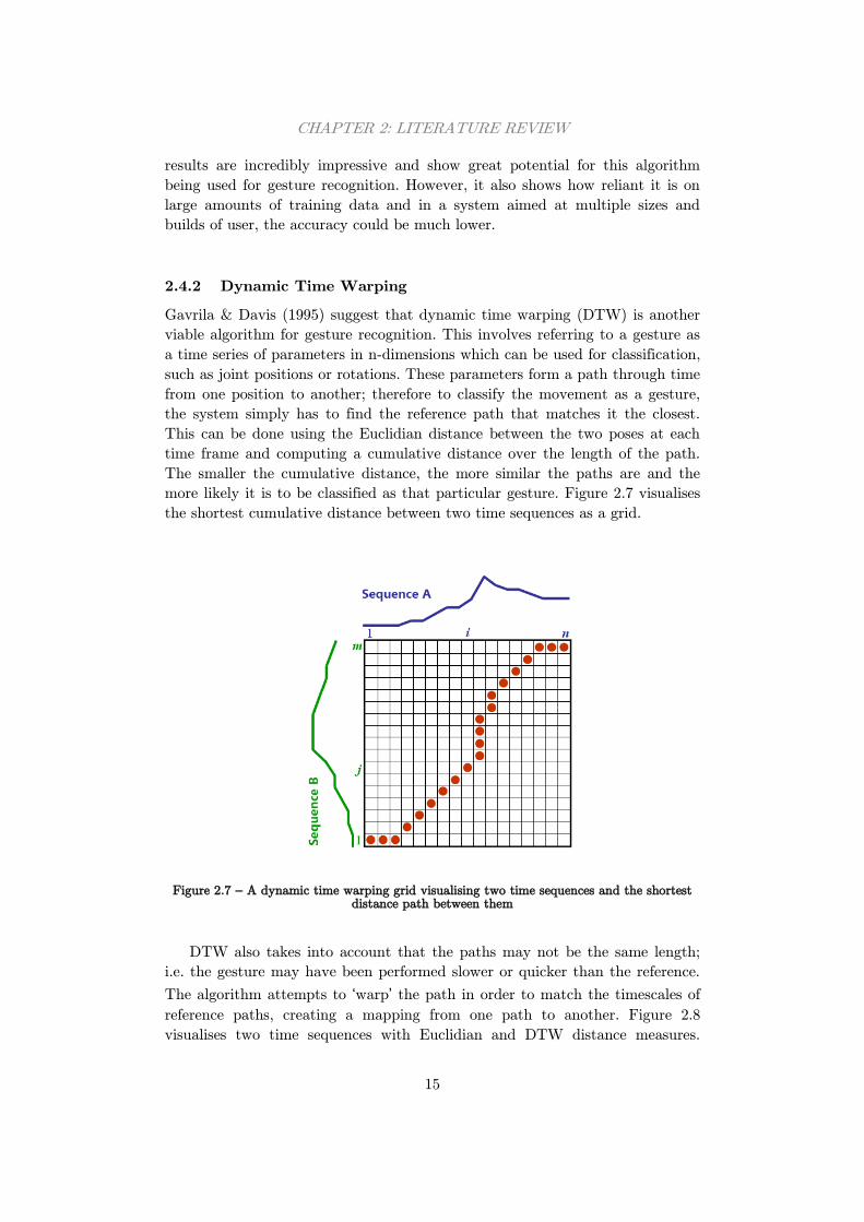
2.4.2 Dynamic Time Warping
Gavrila & Davis (1995) suggest that dynamic time warping (DTW) is another
viable algorithm for gesture recognition. This involves referring to a gesture as
a time series of parameters in n-dimensions which can be used for classification,
such as joint positions or rotations. These parameters form a path through time
from one position to another; therefore to classify the movement as a gesture,
the system simply has to find the reference path that matches it the closest.
This can be done using the Euclidian distance between the two poses at each
time frame and computing a cumulative distance over the length of the path.
The smaller the cumulative distance, the more similar the paths are and the
more likely it is to be classified as that particular gesture. Figure 2.7 visualises
the shortest cumulative distance between two time sequences as a grid.
Figure 2.7 – A dynamic time warping grid visualising two time sequences and the shortest distance path between them
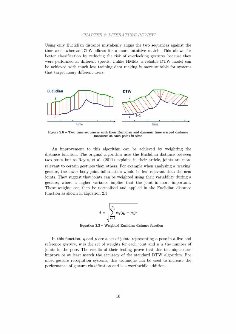
DTW also takes into account that the paths may not be the same length;
i.e. the gesture may have been performed slower or quicker than the reference.
The algorithm attempts to ‘warp’ the path in order to match the timescales of
reference paths, creating a mapping from one path to another. Figure 2.8
visualises two time sequences with Euclidian and DTW distance measures.
CHAPTER 2: LITERATURE REVIEW
16
Using only Euclidian distance mistakenly aligns the two sequences against the
time axis, whereas DTW allows for a more intuitive match. This allows for
better classification by reducing the risk of overlooking gestures because they
were performed at different speeds. Unlike HMMs, a reliable DTW model can
be achieved with much less training data making it more suitable for systems
that target many different users.
Figure 2.8 – Two time sequences with their Euclidian and dynamic time warped distance
measures at each point in time
An improvement to this algorithm can be achieved by weighting the
distance function. The original algorithm uses the Euclidian distance between
two poses but as Reyes, et al. (2011) explains in their article, joints are more
relevant to certain gestures than others. For example when analysing a ‘waving’
gesture, the lower body joint information would be less relevant than the arm
joints. They suggest that joints can be weighted using their variability during a
gesture, where a higher variance implies that the joint is more important.
These weights can then be normalised and applied in the Euclidian distance
function as shown in Equation 2.3.
√∑ ( )
Equation 2.3 – Weighted Euclidian distance function
In this function, q and p are a set of joints representing a pose in a live and
reference gesture, w is the set of weights for each joint and n is the number of
joints in the pose. The results of their testing prove that this technique does
improve or at least match the accuracy of the standard DTW algorithm. For
most gesture recognition systems, this technique can be used to increase the
performance of gesture classification and is a worthwhile addition.
17
Chapter 3: Requirements and Analysis
This section will outline the projects aims and objectives, and also the criteria
that will be used to evaluate the success of the system. Defining goals allows
for a clear development path and will help to create a system that is fit for
purpose. The project will also be broken down into smaller sections which will
be explained in turn.
3.1 System Requirements
As this project is relatively open-ended, there were few set requirements at the
start of the project. It had many different paths that could be explored which
would produce various different systems. Based on the project description, the
following requirements were defined:
The system must be able to display shadow puppets on screen
Users must interact with the system using a Microsoft Kinect device
The puppets will be manipulated by the movements of the user via
the Kinect device
The system must allow users to make (and record) shadow plays
using the puppets
Image processing techniques must be used to add realism
These requirements form a basis for the system, providing a starting point
for development. However, these requirements only define the fundamentals of
the system, and further research was needed to give the project a more definite
end goal.
After conducting the research outlined in Section 2, the system was broken
down into four distinct areas that would be worked on: using the Kinect to
track users and control puppets on screen, allowing users to record their
shadow plays, to provide realistic effects such as blurring using image
processing techniques and finally, to allow users to control the system using
gesture recognition. These enhance the system in different ways but all four are
required to make a system that is suitable for its end purpose. From this, a set
of functional and non-functional requirements were defined outlined in Table
3.1 and Table 3.2, which can be used to evaluate the system at the end of the
project. Requirements are categorised by importance, where essential
requirements must be completed, desirable requirements would be important
but not required for the system to function, and optional requirements are
those which provide additional functionality if there is time at the end of the
project.
CHAPTER 3: REQUIREMENTS AND ANALYSIS
18
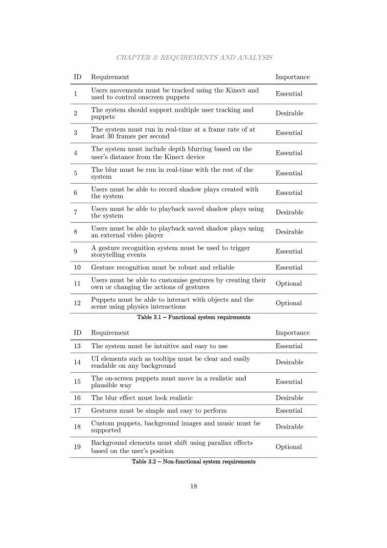
ID Requirement Importance
1 Users movements must be tracked using the Kinect and used to control onscreen puppets
Essential
2 The system should support multiple user tracking and puppets
Desirable
3 The system must run in real-time at a frame rate of at least 30 frames per second
Essential
4 The system must include depth blurring based on the
user’s distance from the Kinect device Essential
5 The blur must be run in real-time with the rest of the system
Essential
6 Users must be able to record shadow plays created with the system
Essential
7 Users must be able to playback saved shadow plays using the system
Desirable
8 Users must be able to playback saved shadow plays using an external video player
Desirable
9 A gesture recognition system must be used to trigger storytelling events
Essential
10 Gesture recognition must be robust and reliable Essential
11 Users must be able to customise gestures by creating their own or changing the actions of gestures
Optional
12 Puppets must be able to interact with objects and the scene using physics interactions
Optional
Table 3.1 – Functional system requirements
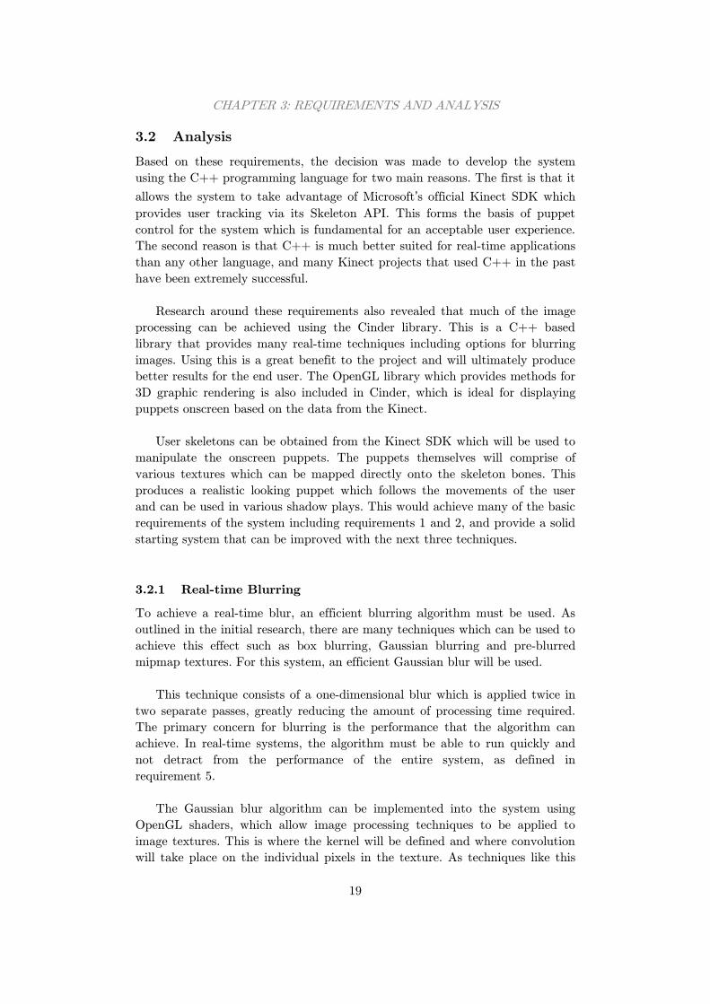
ID Requirement Importance
13 The system must be intuitive and easy to use Essential
14 UI elements such as tooltips must be clear and easily readable on any background
Desirable
15 The on-screen puppets must move in a realistic and plausible way
Essential
16 The blur effect must look realistic Desirable
17 Gestures must be simple and easy to perform Essential
18 Custom puppets, background images and music must be supported
Desirable
19 Background elements must shift using parallax effects
based on the user’s position Optional
Table 3.2 – Non-functional system requirements
CHAPTER 3: REQUIREMENTS AND ANALYSIS
19
3.2 Analysis
Based on these requirements, the decision was made to develop the system
using the C++ programming language for two main reasons. The first is that it
allows the system to take advantage of Microsoft’s official Kinect SDK which
provides user tracking via its Skeleton API. This forms the basis of puppet
control for the system which is fundamental for an acceptable user experience.
The second reason is that C++ is much better suited for real-time applications
than any other language, and many Kinect projects that used C++ in the past
have been extremely successful.
Research around these requirements also revealed that much of the image
processing can be achieved using the Cinder library. This is a C++ based
library that provides many real-time techniques including options for blurring
images. Using this is a great benefit to the project and will ultimately produce
better results for the end user. The OpenGL library which provides methods for
3D graphic rendering is also included in Cinder, which is ideal for displaying
puppets onscreen based on the data from the Kinect.
User skeletons can be obtained from the Kinect SDK which will be used to
manipulate the onscreen puppets. The puppets themselves will comprise of
various textures which can be mapped directly onto the skeleton bones. This
produces a realistic looking puppet which follows the movements of the user
and can be used in various shadow plays. This would achieve many of the basic
requirements of the system including requirements 1 and 2, and provide a solid
starting system that can be improved with the next three techniques.
3.2.1 Real-time Blurring
To achieve a real-time blur, an efficient blurring algorithm must be used. As
outlined in the initial research, there are many techniques which can be used to
achieve this effect such as box blurring, Gaussian blurring and pre-blurred
mipmap textures. For this system, an efficient Gaussian blur will be used.
This technique consists of a one-dimensional blur which is applied twice in
two separate passes, greatly reducing the amount of processing time required.
The primary concern for blurring is the performance that the algorithm can
achieve. In real-time systems, the algorithm must be able to run quickly and
not detract from the performance of the entire system, as defined in
requirement 5.
The Gaussian blur algorithm can be implemented into the system using
OpenGL shaders, which allow image processing techniques to be applied to
image textures. This is where the kernel will be defined and where convolution
will take place on the individual pixels in the texture. As techniques like this
CHAPTER 3: REQUIREMENTS AND ANALYSIS
20
have been used in other systems successfully, this implementation should
satisfy the performance requirement. It should also meet requirement 16 where
the blur looks realistic and visually appealing. However, if this technique turns
out to be infeasible and either of these requirements cannot be met, an
alternative blurring technique will be chosen.
Alternatives such as a box blur would attain better performance than a
Gaussian blur, which is critical in this system. This however is at the expense
of realism, producing a less visually attractive blur which may cause
requirement 16 to not be met. Based on the importance of the two
requirements, performance takes priority over realism and a box blur may end
up being more feasible for this system, if the Gaussian blur does not meet the
performance requirements.
3.2.2 Recording Shadow Plays
The next area which will be addressed is the ability for users to record their
shadow plays. There are two approaches which could be used to achieve this
requirement. The first is to record plays into a custom file which can be read
back in and played back using only the system. The second option would save
the story as a video file which can be played back using external video players
and shared with friends or uploaded to the internet. Ideally, both options are to
be implemented, but this is time permitting.
The first option is more challenging than the second but can be
accomplished using standard C++ file streams. The system would be able to
create new files, write all the necessary data to the file and then close it once
done. This data would be in the form of parameters such as the 3D position of
the user which can be used to playback the story as if the data came directly
from the Kinect, fulfilling requirements 6 and 7. These files would be nonsense
to anything other than this system, which would be the only way of playing
back a saved play.
These files will be read back using the same file streams and the data can
be parsed back into their correct data types. However, this would require
validation to ensure that invalid files would not crash the system. Another
problem is deciding on a suitable format for the files that allows the stories to
be played back exactly as they were recorded, and with multiple users. These
considerations will need to be addressed to ensure the file handling is robust.
The second option for recording plays is to export the story as a video file.
For this, an external library would be needed to encode the frame data into the
correct video format as it is being performed. This option means that the
system is not needed to play back the story, allowing it to be shared with a
wider audience such as the internet, fulfilling requirements 6 and 8. However,
there are problems with this technique. For instance, video exporting is known
CHAPTER 3: REQUIREMENTS AND ANALYSIS
21
to be a slow process and doing this whilst rendering live data in real-time may
not be viable. Also, a compatible library to export data as it is seen onscreen
may not be available for this type of project. Tests will also need to be
performed to choose the optimum exporting settings, such as resolution, quality
and file size.
3.2.3 Gesture Recognition
The third core feature that will be implemented into the system is gesture
recognition support. Gestures will be used to trigger events, particularly whilst
the user is recording a shadow play. These actions include being able to change
visual elements such as the puppet and background, and also being able to
start and stop recordings without having to go near the machine running the
system. This will cover requirements 9 and 10.
The gesture recognition system that will be implemented will use the
dynamic time warping (DTW) algorithm explained in Section 2.4.2. Pre-
recorded gestures will be stored in an external file, which will be used as a
reference when a gesture is performed by the user. The user’s gesture will be
compared with each of the pre-recorded gestures to find the closest match. If a
pre-recorded gesture matches the user’s gesture within a fixed threshold, the
gesture will be recognised, otherwise it will be ignored.
Gestures will consist of a series of frames, each made up with a set of
parameters which can be used to identify the users pose at that frame. These
frames will represent a short movement, such as raising both arms in the air,
much like a short recorded shadow play. These large sets of parameters can be
passed to the DTW algorithm to compute similarity scores between two
different gestures.
To identify gestures, the system must store previous frames where the user
is visible. A fixed amount of frames will be stored (the same number of frames
as a gesture) and if the number of stored frames exceeds this amount, the
oldest frames will be removed. Once this amount is reached, the system can run
the DTW algorithm on these stored frames and the pre-recorded gesture frames
to identify any matches.
One drawback of using gesture recognition in this system is that puppets
can only rotate their joints in two dimensions. The puppet as a whole will be
able to move forwards and backwards in 3D space, but they are always facing
forwards meaning that they are projected as 2D. This limits the number of
gestures available, as many gesture recognition systems benefit from 3D depth
data to identify when to look for gestures, such as the user placing their hand
in front of the rest of their body. This means that the gestures in this system
will consist of only shoulder and elbow movements.
CHAPTER 3: REQUIREMENTS AND ANALYSIS
22
Another problem which may be faced is the performance of the recognition.
Adding more gestures to the system will increase the amount of calculations
required and will reduce the performance of the entire system. In a real-time
system like this one, this could prove to be a problem and an alternative
method may be needed. For instance, gesture recognition could be computed
less regularly than once every frame, reducing the processing required.
To cover requirement 11, an additional recording method must be
implemented that would allow the user to record their own gestures. This
would also require some form of editor that would allow the user to modify
their recorded gesture, and modify the existing pre-recorded gestures. This is a
large amount of work and would require a lengthy period of time to implement.
Being only an optional requirement, this will be considered at the end of the
project if there is time remaining.
3.3 Testing and Evaluation
System testing and evaluation is one of the most important parts of any
development project. Its main purpose is to find errors and bugs in the
software but it also plays a big role when evaluating the system’s success. In
the development of this system, the testing will be split into two main areas:
unit testing and system testing. The former will verify that there are no errors
in the code and that it performs as expected, and the latter will compare the
system against the requirements to measure how successful it is.
The majority of unit testing will take place after each new feature has been
implemented in line with the iterative and incremental development technique
explained in more detail in Section 4.1. Most errors will be highlighted when
compiling the updated code, which will indicate any syntactical errors or major
problems. The feature will then be tested appropriately to confirm that it
behaves as planned, and also to make sure that it can handle error cases
correctly before moving onto to the next new feature.
System testing will be ongoing much like unit testing, but will feature more
heavily at the end of development. This is when the system is analysed to
ensure it meets all the requirements. As there are many different elements to
this system, each particular area will need to be tested in a different way. For
instance, gesture recognition will need to be tested for accuracy and reliability
using various test users, whereas a questionnaire will be used to gather the
suitability and usability of the system as a whole. Therefore, this area of
testing varies greatly and will be broken down into the key components of the
system.

CHAPTER 3: REQUIREMENTS AND ANALYSIS
23
Both sections of testing are key factors in terms of evaluating the system. A
fully working system is only half of the success criteria for this project; the
other half is based on how well the system meets the requirements of the
project. Using a questionnaire to get users feedback on all aspects of the system
will provide an insight into the strongest and weakest areas of the system. The
target audience which the questionnaire will be aimed at will be able to give
feedback from their point of view, highlighting any areas which may have been
overlooked. Based on their happiness, the formal requirements analysis and the
quality of the code, well-informed conclusions can be made forming a reliable
evaluation of the system.
24
Chapter 4: Design
This section of the report will discuss the design of the system as generated
from the requirements. Key sections of the system will be explained along with
any key decisions made in these areas. The development model used
throughout the project will also be discussed.
4.1 Methodology
For software development projects such as this one, it is beneficial to adopt a
development model. There are a wide range of models available for all types of
project, and each utilise different development techniques. Due to the nature of
this project, an iterative and incremental approach was decided. As the project
began open ended, the needs of the target audience would undoubtedly change,
and therefore the requirements would need to be refined on several occasions.
The model chosen is highly appropriate for this project given its short
development cycles.
The core functionality of the system can be implemented early on in
development, followed by the addition of new features and constant
improvement over time. For instance, the basic functionality of controlling
puppets using the Kinect can be achieved early on, whilst extra additions such
as blurring and gestures can be added afterwards. Cockburn (2008) explains
that in the model, this is represented by the iterative step where working
prototypes are produced at various stages of development, showcasing the
latest features implemented into the system and allowing the user to give
feedback on the system in its current state, including half developed features.
The model also puts emphasis on testing after each iteration of
development. This ensures that any new features are being implemented
correctly and that bugs introduced are identified and fixed before moving onto
the next iteration. An alternative model which could be used is the agile
development model, as defined by Beck (2001). Like the iterative and
incremental model, agile focuses on small prototypes being developed and
reviewed by the target audience before continuing. However, each prototype
must include a fully implemented new feature, rather than adding and refining
what has already been developed. Due to the time constraints in this project,
the agile model may not be as suitable as the iterative and incremental model.

CHAPTER 4: DESIGN
25
4.2 System Overview
Like many other graphical applications, the shadow puppet system continually
loops and redraws images to the application window. Each redraw is known as
a frame, where real-time applications should be able to display around thirty
frames per second. Redrawing allows the application to display new images in
the window, creating an animation and simulating motion of objects. In this
system the majority of the processing is repeated each frame bar any setup or
loading of resources. Figure 4.1 gives an overview of how the system operates
and what processes are involved to display and animate puppets onscreen.
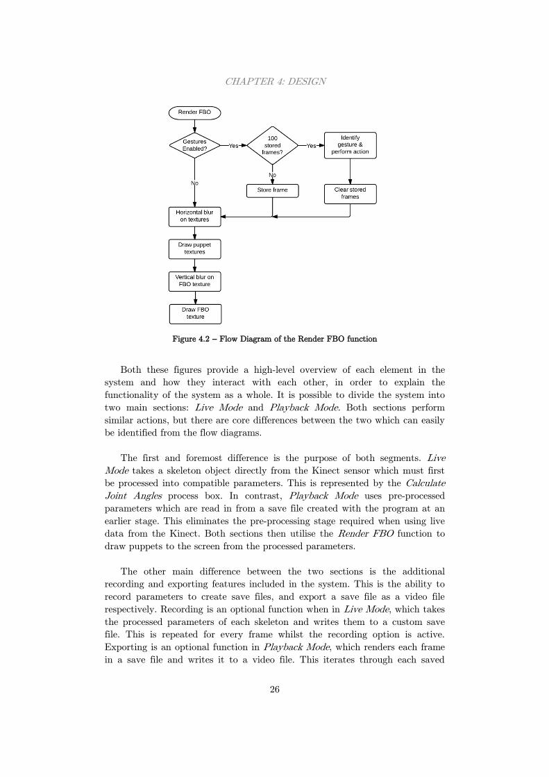
Figure 4.2 outlines the Render FBO function, which is separated from the main
flow diagram for simplicity.
Figure 4.1 – Flow Diagram of the system
CHAPTER 4: DESIGN
26
Figure 4.2 – Flow Diagram of the Render FBO function
Both these figures provide a high-level overview of each element in the
system and how they interact with each other, in order to explain the
functionality of the system as a whole. It is possible to divide the system into
two main sections: Live Mode and Playback Mode. Both sections perform
similar actions, but there are core differences between the two which can easily
be identified from the flow diagrams.
The first and foremost difference is the purpose of both segments. Live
Mode takes a skeleton object directly from the Kinect sensor which must first
be processed into compatible parameters. This is represented by the Calculate
Joint Angles process box. In contrast, Playback Mode uses pre-processed
parameters which are read in from a save file created with the program at an
earlier stage. This eliminates the pre-processing stage required when using live
data from the Kinect. Both sections then utilise the Render FBO function to
draw puppets to the screen from the processed parameters.
The other main difference between the two sections is the additional
recording and exporting features included in the system. This is the ability to
record parameters to create save files, and export a save file as a video file
respectively. Recording is an optional function when in Live Mode, which takes
the processed parameters of each skeleton and writes them to a custom save
file. This is repeated for every frame whilst the recording option is active.
Exporting is an optional function in Playback Mode, which renders each frame
in a save file and writes it to a video file. This iterates through each saved
CHAPTER 4: DESIGN
27
frame until the end of the file, at which point the system then returns to Live
Mode. Both these features enhance the storytelling aspect of the application,
and allow users to record and share their stories with their friends. In Section
5.1.4, these features will be discussed in more detail.
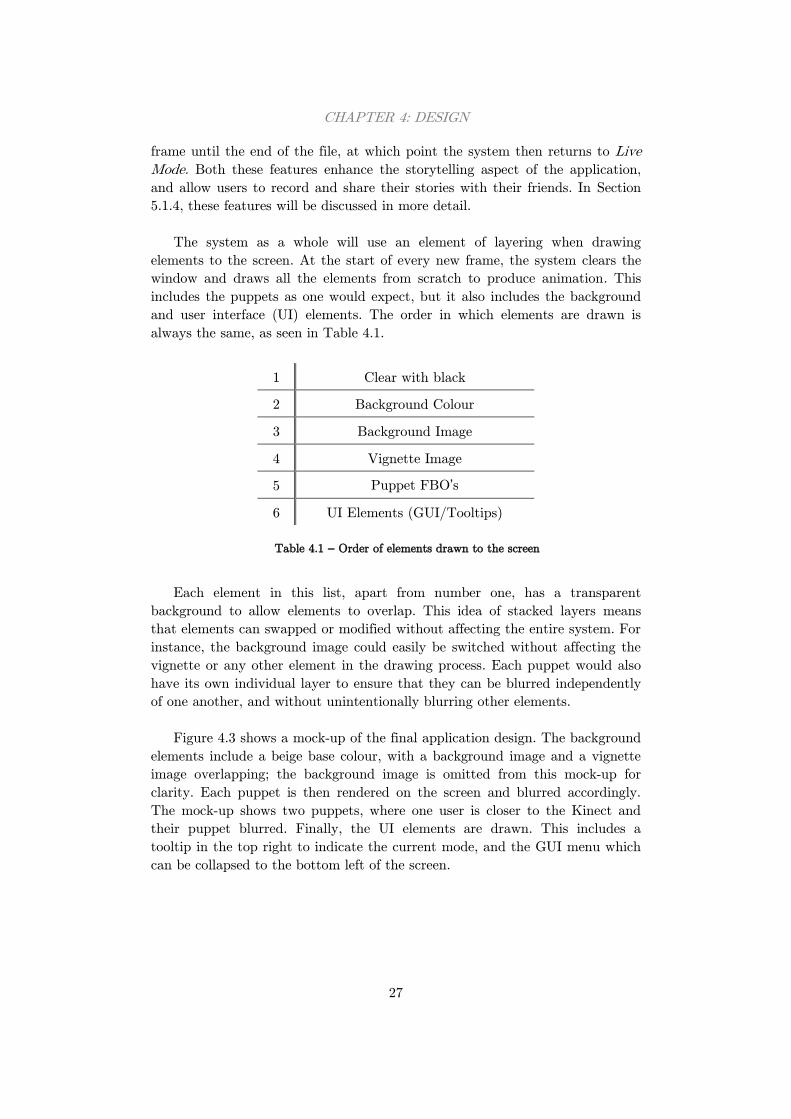
The system as a whole will use an element of layering when drawing
elements to the screen. At the start of every new frame, the system clears the
window and draws all the elements from scratch to produce animation. This
includes the puppets as one would expect, but it also includes the background
and user interface (UI) elements. The order in which elements are drawn is
always the same, as seen in Table 4.1.
1 Clear with black
2 Background Colour
3 Background Image
4 Vignette Image
5 Puppet FBO’s
6 UI Elements (GUI/Tooltips)
Table 4.1 – Order of elements drawn to the screen
Each element in this list, apart from number one, has a transparent
background to allow elements to overlap. This idea of stacked layers means
that elements can swapped or modified without affecting the entire system. For
instance, the background image could easily be switched without affecting the
vignette or any other element in the drawing process. Each puppet would also
have its own individual layer to ensure that they can be blurred independently
of one another, and without unintentionally blurring other elements.
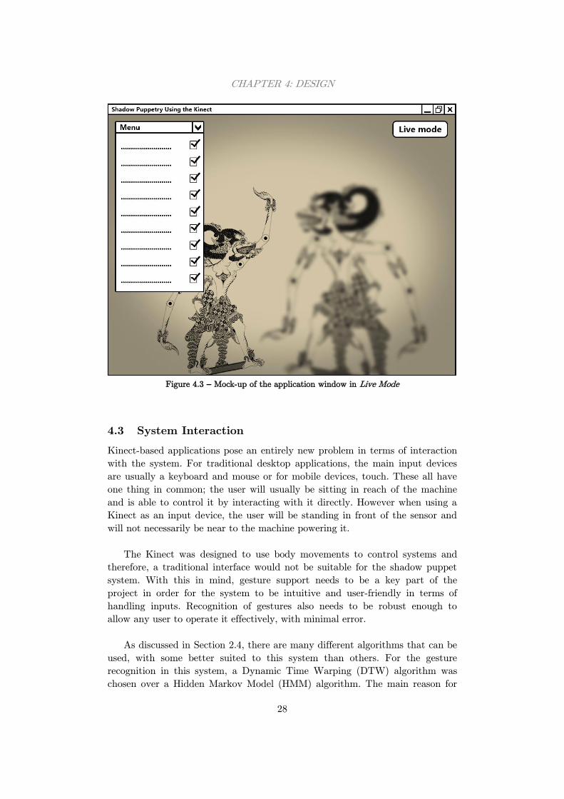
Figure 4.3 shows a mock-up of the final application design. The background
elements include a beige base colour, with a background image and a vignette
image overlapping; the background image is omitted from this mock-up for
clarity. Each puppet is then rendered on the screen and blurred accordingly.
The mock-up shows two puppets, where one user is closer to the Kinect and
their puppet blurred. Finally, the UI elements are drawn. This includes a
tooltip in the top right to indicate the current mode, and the GUI menu which
can be collapsed to the bottom left of the screen.
CHAPTER 4: DESIGN
28
Figure 4.3 – Mock-up of the application window in Live Mode
4.3 System Interaction
Kinect-based applications pose an entirely new problem in terms of interaction
with the system. For traditional desktop applications, the main input devices
are usually a keyboard and mouse or for mobile devices, touch. These all have
one thing in common; the user will usually be sitting in reach of the machine
and is able to control it by interacting with it directly. However when using a
Kinect as an input device, the user will be standing in front of the sensor and
will not necessarily be near to the machine powering it.
The Kinect was designed to use body movements to control systems and
therefore, a traditional interface would not be suitable for the shadow puppet
system. With this in mind, gesture support needs to be a key part of the
project in order for the system to be intuitive and user-friendly in terms of
handling inputs. Recognition of gestures also needs to be robust enough to
allow any user to operate it effectively, with minimal error.
As discussed in Section 2.4, there are many different algorithms that can be
used, with some better suited to this system than others. For the gesture
recognition in this system, a Dynamic Time Warping (DTW) algorithm was
chosen over a Hidden Markov Model (HMM) algorithm. The main reason for
CHAPTER 4: DESIGN
29
this decision was that DTW performs better than HMM with a small amount
of training data. As this is a real-time system, the amount of training data has
to be small to avoid impacting performance. It is also not viable to collect a
large amount of training data for every possible case so the system needs to
build a model from a small sample of data.
In this system, there are only a few gesture-triggered user interactions
which will be implemented, and all of them help to aid the storytelling
experience. There are three gestures to change the puppet, the background
image and the music and there are two gestures for sharing stories. The first of
these toggles live recording which when enabled, writes each frame to a save
file that only the application can read. The second gesture switches to playback
mode. When triggered, this allows users to open a save file to be played back in
the application. However, once in playback mode there is no gesture to return
to live mode, as the live data is not being analysed. In Section 5.1.5, the
gesture recognition system will be explained in more detail, including the
implementation of a DTW algorithm and how gestures are performed and
stored.
Whilst gesture recognition is used primarily for the storytelling related
settings, there are elements of the system that cannot be controlled by a
gesture. These are settings that would not alter the story being told, and are
likely only changed before or after stories have been performed. These settings
include Kinect specific options such as whether to use Near Mode and also
include application settings including music volume, toggling the flicker effect
or showing/hiding gesture hints. Finally, there are options to toggle between
live and playback modes, export a video or quit the application altogether.
To change these application settings, the system needs to include a
graphical user interface (GUI) which can be controlled using traditional input
devices such as a keyboard and mouse. As the application is built using the
Cinder framework, it makes sense to use the built in AntTweakBar library.
This is a small OpenGL GUI designed for graphical applications such as this
one. It allows parameters and settings to be easily changed whilst the
application is running, and can be minimised as to not detract from the main
use of the system. It also supports hotkeys to allow settings to be toggled using
only the keyboard.
The final user interaction that is required is when opening or saving files.
Again, this is not suitable for gesture control as users are required to either
type a filename or select a file from a set of directories. These tasks require
more precision than gestures can provide, and can be performed much quicker
using traditional input methods. For this reason, the shadow puppet system
will use the Boost.Filesystem library to open a dialog window and allow the
user to save or open a file of their choice. This is used in conjunction with the
CHAPTER 4: DESIGN
30
fstream class built into C++ to read and write to the file in question, allowing
the system to save and playback stories even if the application is closed. Using
both gestures and other interaction elements will make the system intuitive and
easy to use.
4.4 Storytelling
As specified in the outline of this project, the purpose of this system is to be
able to create shadow puppet stories with the use of a Kinect. The characters
in the stories will be controlled by the users, which will be manipulated by the
user moving their body. The characters will appear as traditional Indonesian
style puppets and will have hinged joints at both shoulders and both elbows
allowing for a wide range of movements and poses.
There will be two modes of the system as mentioned earlier in Section 4.2,
Live Mode and Playback Mode. As the first receives data from the Kinect, this
is the mode in which stories will be recorded. Stories can either be recorded to
external save files or exported as video files. Users will be able to initiate
recording by performing a gesture or by pressing a button in the GUI, which
will ask the user to provide a file name and directory to store the story in.
A save file will consist of many lines of parameters; each line will represent
a frame of the story and the parameters are used to identify the position and
pose of puppets in the scene. If multiple puppets appear in the scene at once,
the parameters for both puppets will be stored on the same line in the file. To
separate puppets and to identify when parameters begin and end, a series of
character flags will be used. This also can be used to identify invalid files.
When the user has finished recording their story, they can perform the same
gesture or click the same button in the GUI to stop the system writing to the
save file and to return to Live Mode.
The second mode, Playback Mode, will allow users to play back the stories
they have previously recorded. Again, this can be initiated using a gesture or
with the GUI, and will ask the user to select a save file to open. The system
will then read the parameters stored in the file, as identified by the flags, and
begin to playback the story on loop. The gesture recognition system will also
run in the background as if it were Live Mode to ensure that gestures
performed in the recording still trigger the required actions.
The final option a user will have is to convert a saved story into a video
file. This will be activated using the GUI, which will ask the user to select a
save file to open. Once opened, the system will begin rendering each frame of
the story and storing them into a video file with the same name. This
conversion will use the QuickTime library included with Cinder, which is able
to encode videos using multiple different codecs.
31
Chapter 5: Implementation and Testing
In this section, the system will be broken down into key features and explained
in finer detail. The techniques used to implement each aspect of the system will
be explored and any new or novel ideas will be discussed. This section will also
discuss the methods that will be used to test the system with respect to the
requirements.
5.1 Implementation
There are four key areas of the system that will be discussed in this section and
they are how shadow puppets are rendered using data from the Kinect, the
algorithm used to produce a real-time blur, how stories can be recorded and
saved, and finally how gesture recognition has been implemented. Any extra
novel features are also explained at the end of the section. Before any of these
can be explored however, the programming language and framework must first
be discussed.
5.1.1 Programming Language and Framework
From the initial research in Section 2.3.1, it was discovered that there were two
main programming languages and frameworks that would be suitable for this
system. The first was Java using the Processing framework, and the second is
C++ using the Cinder framework. Both languages have their advantages and
disadvantages, and ultimately it was decided that the system would be written
in C++ and Cinder. The deciding factor for this decision was the performance
advantage of C++ as a language compared to Java, and for a real-time
application such as this one where performance is a measure of success, this
seemed like the most logical option. Also, Cinder is a more powerful framework
than Processing and includes many more features which may reduce
development time and decrease the number of additional external libraries
needed.
The other advantage of using C++ is that the system will be compatible
with the official Kinect SDK, and can take advantage of all the features
provided. This is in contrast to using an open source SDK such as OpenNI,
which would have to be used if the system was developed in Java and
Processing. Although these open source SDKs are very impressive, they would
not match the performance of the official SDK and may be missing core
functionality that could be crucial for the system.
CHAPTER 5: IMPLEMENTATION AND TESTING
32
With this decided, the development environment would be Microsoft Visual
Studio 2010 on a Microsoft Windows machine. As the end users will also be
using Microsoft Windows machines to use the system, it makes sense to
develop the system on the same operating system with similar hardware. The
development machine also includes a dedicated graphical processing unit
(GPU) in the form of an Nvidia GTX 660M, as well as an integrated laptop
GPU. This allows the system to be tested on standard laptop hardware, but
also on a machine with more graphical processing power, giving an indication
of the systems efficiency.
One final note is that an additional library would be needed to allow the
Kinect SDK to be used with Cinder, which can be achieved by using
CinderBlocks. These are small collections of libraries and code that allow
additional features to be implemented into Cinder, usually bridging to other
SDK’s. For this system, the KinectSDK for Cinder block will be used to
communicate with the Kinect via its SDK.
5.1.2 Rendering Shadow Puppets
The most core functionality of the system is its ability to track users using the
Kinect and represent them onscreen as shadow puppets. Tracking users is the
simplest task in this section, as the official SDK provides this functionality in
its Skeleton API. Users are represented as a set of key joints in 3D space which
are connected by bones to create a full skeleton. These points provide enough
information for puppets to be manipulated to mimic the user’s actions.
There are multiple ways of using a Kinect skeleton to manipulate puppets;
the easiest is to attach an individual puppet image to each bone in the
skeleton. Figure 5.1 shows how a puppet is split into three images to allow
movable joints at the shoulder and elbow. These are loaded in as OpenGL
Textures and given u, v coordinates. The arm sections can be reused for both
the left and right arm to save memory usage, and each image has an aspect
ratio of 1:1 and a resolution to a power of two where possible. The centre of
each image is the anchor point at which to rotate the image, and the black dots
indicate where the images should be attached.

CHAPTER 5: IMPLEMENTATION AND TESTING
33
Puppet 1 Body Puppet 1 Lower Arm Puppet 1 Upper Arm
Figure 5.1 – The three puppet textures used for Puppet 1
By attaching each of these images to a bone, there immediately becomes a
problem. Skeletons are calculated by fitting joints to a user as they best fit
meaning that skeletons can be all shapes and sizes to suit different users. When
puppet textures are attached, there is no guarantee that the arms will be
anchored correctly for everyone causing the arms to detach from the body
completely. The same problem applies for different puppets with different body
frames. For these reasons, images on bones would not be suitable for this
application.
An alternative technique, and the technique used in this system is to attach
the body image to the skeleton’s waist joint, and position the arm images
relative to this using transformations. This means that no matter what skeleton
was produced, the puppet images will always line up correctly. Relative images
can be easily achieved using OpenGL matrices to push and pop transformations
onto a stack before they are drawn. This approach requires a specific set of
transformations for each puppet, but this is reasonable for a small number of
puppets. The image textures can be rendered onto 3D billboard objects and
displayed in 3D space to utilise the depth information from the Kinect.
The next step is to rotate the images based on the user’s movements. Joints
are simply a point in 3D space and provide no information about the angle and
direction they are facing so these rotations must be calculated manually. Using
two joints, it is possible to calculate the angle of the bone in respect to the x-
axis using the std::atan2 function defined by Equation 5.1.
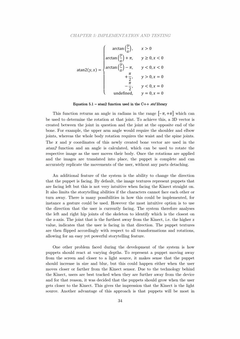
CHAPTER 5: IMPLEMENTATION AND TESTING
34
( )
{
(
)
(
)
(
)
Equation 5.1 – atan2 function used in the C++ std library
This function returns an angle in radians in the range [– ] which can
be used to determine the rotation at that joint. To achieve this, a 3D vector is
created between the joint in question and the joint at the opposite end of the
bone. For example, the upper arm angle would require the shoulder and elbow
joints, whereas the whole body rotation requires the waist and the spine joints.
The and coordinates of this newly created bone vector are used in the
atan2 function and an angle is calculated, which can be used to rotate the
respective image as the user moves their body. Once the rotations are applied
and the images are translated into place, the puppet is complete and can
accurately replicate the movements of the user, without any parts detaching.
An additional feature of the system is the ability to change the direction
that the puppet is facing. By default, the image textures represent puppets that
are facing left but this is not very intuitive when facing the Kinect straight on.
It also limits the storytelling abilities if the characters cannot face each other or
turn away. There is many possibilities in how this could be implemented, for
instance a gesture could be used. However the most intuitive option is to use
the direction that the user is currently facing. The system therefore analyses
the left and right hip joints of the skeleton to identify which is the closest on
the z-axis. The joint that is the furthest away from the Kinect, i.e. the higher z
value, indicates that the user is facing in that direction. The puppet textures
are then flipped accordingly with respect to all transformations and rotations,
allowing for an easy yet powerful storytelling feature.
One other problem faced during the development of the system is how
puppets should react at varying depths. To represent a puppet moving away
from the screen and closer to a light source, it makes sense that the puppet
should increase in size and blur, but this could happen either when the user
moves closer or farther from the Kinect sensor. Due to the technology behind
the Kinect, users are best tracked when they are further away from the device
and for that reason, it was decided that the puppets should grow when the user
gets closer to the Kinect. This gives the impression that the Kinect is the light
source. Another advantage of this approach is that puppets will be most in
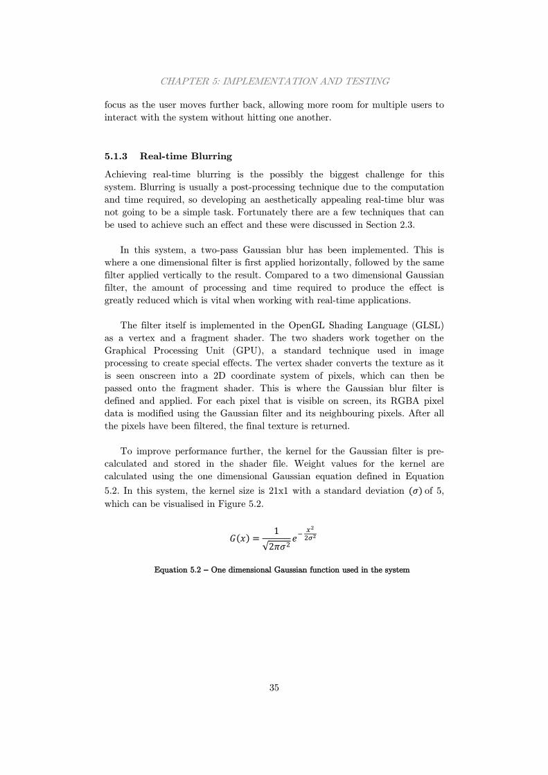
CHAPTER 5: IMPLEMENTATION AND TESTING
35
focus as the user moves further back, allowing more room for multiple users to
interact with the system without hitting one another.
5.1.3 Real-time Blurring
Achieving real-time blurring is the possibly the biggest challenge for this
system. Blurring is usually a post-processing technique due to the computation
and time required, so developing an aesthetically appealing real-time blur was
not going to be a simple task. Fortunately there are a few techniques that can
be used to achieve such an effect and these were discussed in Section 2.3.
In this system, a two-pass Gaussian blur has been implemented. This is
where a one dimensional filter is first applied horizontally, followed by the same
filter applied vertically to the result. Compared to a two dimensional Gaussian
filter, the amount of processing and time required to produce the effect is
greatly reduced which is vital when working with real-time applications.
The filter itself is implemented in the OpenGL Shading Language (GLSL)
as a vertex and a fragment shader. The two shaders work together on the
Graphical Processing Unit (GPU), a standard technique used in image
processing to create special effects. The vertex shader converts the texture as it
is seen onscreen into a 2D coordinate system of pixels, which can then be
passed onto the fragment shader. This is where the Gaussian blur filter is
defined and applied. For each pixel that is visible on screen, its RGBA pixel
data is modified using the Gaussian filter and its neighbouring pixels. After all
the pixels have been filtered, the final texture is returned.
To improve performance further, the kernel for the Gaussian filter is pre-
calculated and stored in the shader file. Weight values for the kernel are
calculated using the one dimensional Gaussian equation defined in Equation
5.2. In this system, the kernel size is 21x1 with a standard deviation ( ) of 5,
which can be visualised in Figure 5.2.
( )
√
Equation 5.2 – One dimensional Gaussian function used in the system
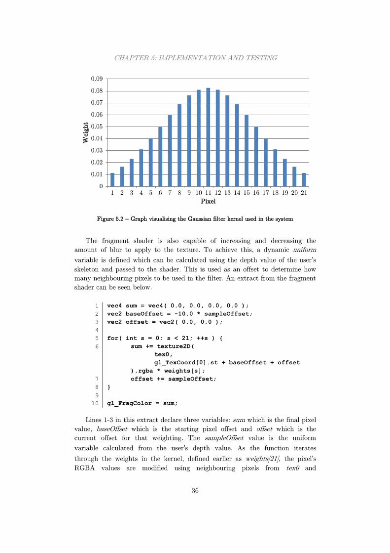
CHAPTER 5: IMPLEMENTATION AND TESTING
36
Figure 5.2 – Graph visualising the Gaussian filter kernel used in the system
The fragment shader is also capable of increasing and decreasing the
amount of blur to apply to the texture. To achieve this, a dynamic uniform
variable is defined which can be calculated using the depth value of the user’s
skeleton and passed to the shader. This is used as an offset to determine how
many neighbouring pixels to be used in the filter. An extract from the fragment
shader can be seen below.
1
2
3
4
5
6
7
8
9
10
vec4 sum = vec4( 0.0, 0.0, 0.0, 0.0 );
vec2 baseOffset = -10.0 * sampleOffset;
vec2 offset = vec2( 0.0, 0.0 );
for( int s = 0; s < 21; ++s ) {
sum += texture2D(
tex0,
gl_TexCoord[0].st + baseOffset + offset
).rgba * weights[s];
offset += sampleOffset;
}
gl_FragColor = sum;
Lines 1-3 in this extract declare three variables: sum which is the final pixel
value, baseOffset which is the starting pixel offset and offset which is the
current offset for that weighting. The sampleOffset value is the uniform
variable calculated from the user’s depth value. As the function iterates
through the weights in the kernel, defined earlier as weights[21], the pixel’s
RGBA values are modified using neighbouring pixels from tex0 and
0
0.01
0.02
0.03
0.04
0.05
0.06
0.07
0.08
0.09
1 2 3 4 5 6 7 8 9 10 11 12 13 14 15 16 17 18 19 20 21
Weig
ht
Pixel
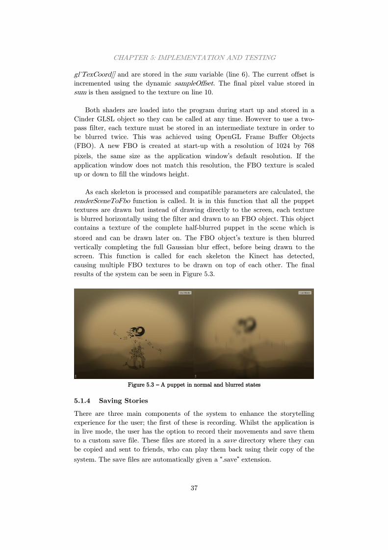
CHAPTER 5: IMPLEMENTATION AND TESTING
37
gl_TexCoord[] and are stored in the sum variable (line 6). The current offset is
incremented using the dynamic sampleOffset. The final pixel value stored in
sum is then assigned to the texture on line 10.
Both shaders are loaded into the program during start up and stored in a
Cinder GLSL object so they can be called at any time. However to use a two-
pass filter, each texture must be stored in an intermediate texture in order to
be blurred twice. This was achieved using OpenGL Frame Buffer Objects
(FBO). A new FBO is created at start-up with a resolution of 1024 by 768
pixels, the same size as the application window’s default resolution. If the
application window does not match this resolution, the FBO texture is scaled
up or down to fill the windows height.
As each skeleton is processed and compatible parameters are calculated, the
renderSceneToFbo function is called. It is in this function that all the puppet
textures are drawn but instead of drawing directly to the screen, each texture
is blurred horizontally using the filter and drawn to an FBO object. This object
contains a texture of the complete half-blurred puppet in the scene which is
stored and can be drawn later on. The FBO object’s texture is then blurred
vertically completing the full Gaussian blur effect, before being drawn to the
screen. This function is called for each skeleton the Kinect has detected,
causing multiple FBO textures to be drawn on top of each other. The final
results of the system can be seen in Figure 5.3.
Figure 5.3 – A puppet in normal and blurred states
5.1.4 Saving Stories
There are three main components of the system to enhance the storytelling
experience for the user; the first of these is recording. Whilst the application is
in live mode, the user has the option to record their movements and save them
to a custom save file. These files are stored in a save directory where they can
be copied and sent to friends, who can play them back using their copy of the
system. The save files are automatically given a “.save” extension.
CHAPTER 5: IMPLEMENTATION AND TESTING
38
The files themselves are custom to the program and contain all the
necessary information required to playback a story, without the need for a
Kinect at all. Each line in the file represents a frame of the recording. On each
line, the frame is represented as a list of parameters which correspond to the
parameters used to draw a puppet. Many puppets parameters can be stored on
the same line using a character flag system. An example frame would be as
follows (where parameters have been reduced in precision for legibility):
# -0.02 -0.18 1.63 0.03 1.60 -0.90 -1.49 1.11 0 *
Each line starts with a ‘#’ character, which tells the system that the
following information represents a puppet. There are eight floating point
numbers depicting the puppets position and pose and one Boolean parameter
indicating the direction the puppet is facing. At the end of each line, or if a
frame does not have any visible puppets, a ‘*’ character is used. For frames
with multiple puppets, the following format would apply:
# <puppet 1 parameters> # <puppet 2 parameters> *
To start recording a story, users can either click a button on the GUI, press
the ‘r’ key or they can perform a gesture. This will bring up a save dialogue
which allows a file name to be chosen for the save file. If the name is valid, the
system will begin recording any new live frames until the recording is stopped
with the GUI or gesture. The top right dialog reads “Recording” and a small
red dot appears in the top right of the window to indicate when the system is
recording. Once stopped, the system closes the save file and returns to Live
Mode.
The second storytelling component of the system is its ability to read in
these save files and playback the recorded story. To load a file, the user must
enter Playback Mode by clicking on a button in the GUI or by pressing the ‘p’
key. This brings up an open file dialog where users can browse their file system
to find the save file they desire. For convenience, the dialog only display files
with the extension “.save”, and will start in the default save directory. If the file
selected is valid, it is read in line by line, the parameters are processed and
parsed and the frames are stored in a vector object. If the file is not valid
however, an exception is thrown during processing and an error message is
displayed.
Once all the processing is completed, the system renders the puppets frame
by frame using the same FBO system as Live Mode. A frame counter
increments every frame and when it equals the size of the frames vector, i.e. the
playback has reached the end, the counter resets and the playback loops back
to the beginning. To reduce file size, gesture information is not stored in the
CHAPTER 5: IMPLEMENTATION AND TESTING
39
save files so they are computed and recognised in the same way as if the data
was live, retaining all aspects of the story.
An option that was considered during the design of the recording and
playback features was whether to auto name save files with the current date
and time. The obvious benefit of this approach is that users would not need to
interact with the system using a mouse and keyboard to choose a file name,
and would be able to control the system entirely with gestures. This is good for
usability but has other drawbacks. For instance, all save files will have
meaningless names and choosing the correct story to share with friends would
prove difficult. The files themselves also have timestamps built in; therefore a
meaningful file name would be more appropriate. Furthermore, the system
would not know which file to load for playback if the user does not get to
choose. It was for these reasons that keyboard and mouse interaction had to be
included in the system for these file handling situations.
The third and final storytelling feature is the ability to render and export
stories as video files. This option allows stories to be uploaded to the internet
or shared with friends who do not own a copy of the system. Unlike the other
two methods, video exporting can only be initialised by pressing a button in
the GUI; there is no gesture to trigger this method. Initially, the system was
developed to export video frames while in Live Mode, much like the current
save file recording system. However upon testing this feature, the performance
of the system dropped to unusable levels and the feature had to be redeveloped.
Instead, it was decided that the system would only be capable of exporting
videos from save files created in advance. This retains the performance of the
system but still keeps the feature included.
When video exporting is activated, the system enters a special mode similar
to Playback Mode where the user must choose a save file to load. It also
creates a new “.mov” file with the same file name where the video will be
written to. The system plays back the file like normal but also records each
frame to the video file as it is seen on screen, before adding some user interface
(UI) elements on top. This means that the video resolution will match that of
the application window and everything, including gestures, will be preserved.
When the playback reaches the end, the system closes the video file and
returns to Live Mode.
Video exporting is handled using the QuickTime Cinder Block included in
the Cinder framework. Videos are encoded using the standard H.264 codec at
75% quality, which ensures that videos files are always small in size whilst still
being visually appealing. The reasoning for these decisions is explained in
Section 6.5 They are also set with a frame rate of 30 frames per second,
meaning that videos will play smoothly whatever hardware they are recorded
or played on.
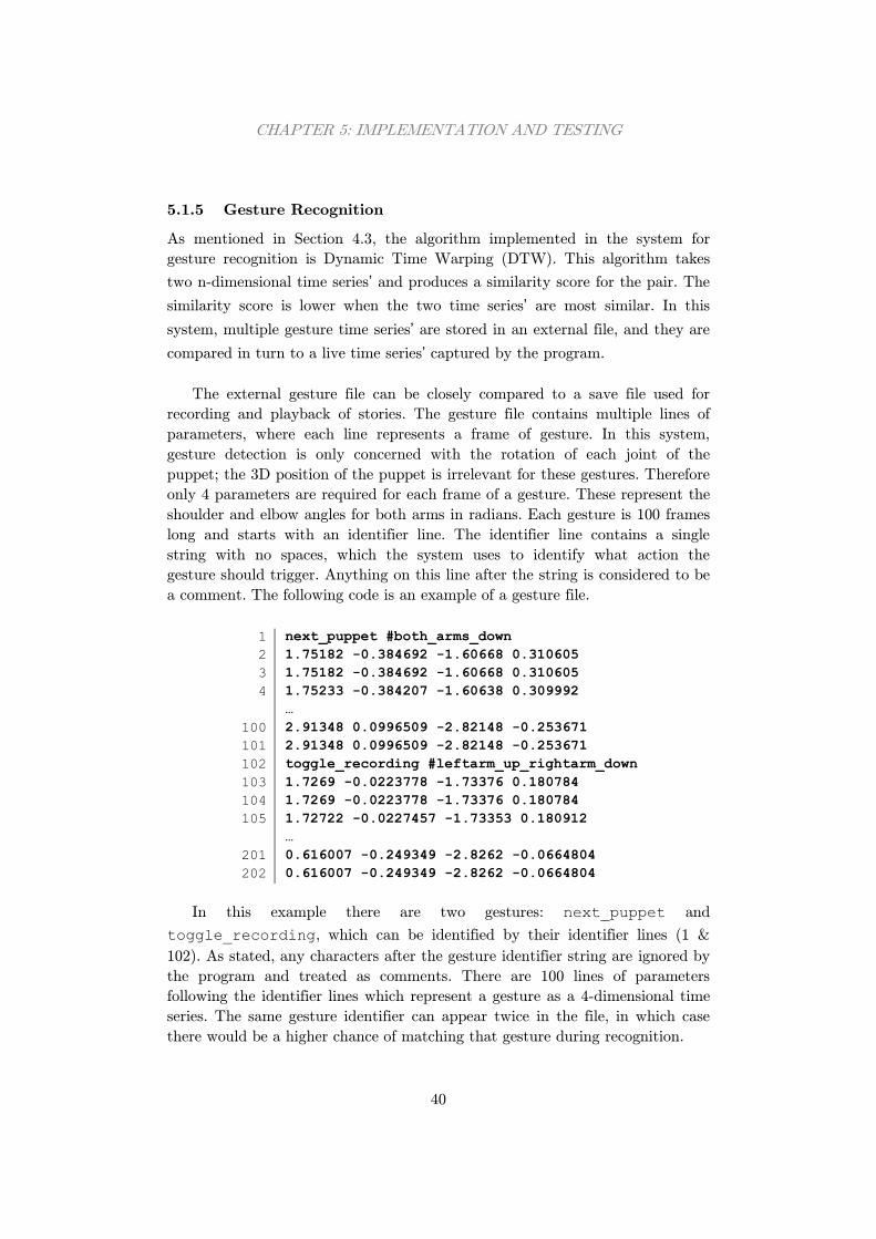
CHAPTER 5: IMPLEMENTATION AND TESTING
40
5.1.5 Gesture Recognition
As mentioned in Section 4.3, the algorithm implemented in the system for
gesture recognition is Dynamic Time Warping (DTW). This algorithm takes
two n-dimensional time series’ and produces a similarity score for the pair. The
similarity score is lower when the two time series’ are most similar. In this
system, multiple gesture time series’ are stored in an external file, and they are
compared in turn to a live time series’ captured by the program.
The external gesture file can be closely compared to a save file used for
recording and playback of stories. The gesture file contains multiple lines of
parameters, where each line represents a frame of gesture. In this system,
gesture detection is only concerned with the rotation of each joint of the
puppet; the 3D position of the puppet is irrelevant for these gestures. Therefore
only 4 parameters are required for each frame of a gesture. These represent the
shoulder and elbow angles for both arms in radians. Each gesture is 100 frames
long and starts with an identifier line. The identifier line contains a single
string with no spaces, which the system uses to identify what action the
gesture should trigger. Anything on this line after the string is considered to be
a comment. The following code is an example of a gesture file.
1
2
3
4
100
101
102
103
104
105
201
202
next_puppet #both_arms_down
1.75182 -0.384692 -1.60668 0.310605
1.75182 -0.384692 -1.60668 0.310605
1.75233 -0.384207 -1.60638 0.309992
…
2.91348 0.0996509 -2.82148 -0.253671
2.91348 0.0996509 -2.82148 -0.253671
toggle_recording #leftarm_up_rightarm_down
1.7269 -0.0223778 -1.73376 0.180784
1.7269 -0.0223778 -1.73376 0.180784
1.72722 -0.0227457 -1.73353 0.180912
…
0.616007 -0.249349 -2.8262 -0.0664804
0.616007 -0.249349 -2.8262 -0.0664804
In this example there are two gestures: next_puppet and
toggle_recording, which can be identified by their identifier lines (1 &
102). As stated, any characters after the gesture identifier string are ignored by
the program and treated as comments. There are 100 lines of parameters
following the identifier lines which represent a gesture as a 4-dimensional time
series. The same gesture identifier can appear twice in the file, in which case
there would be a higher chance of matching that gesture during recognition.
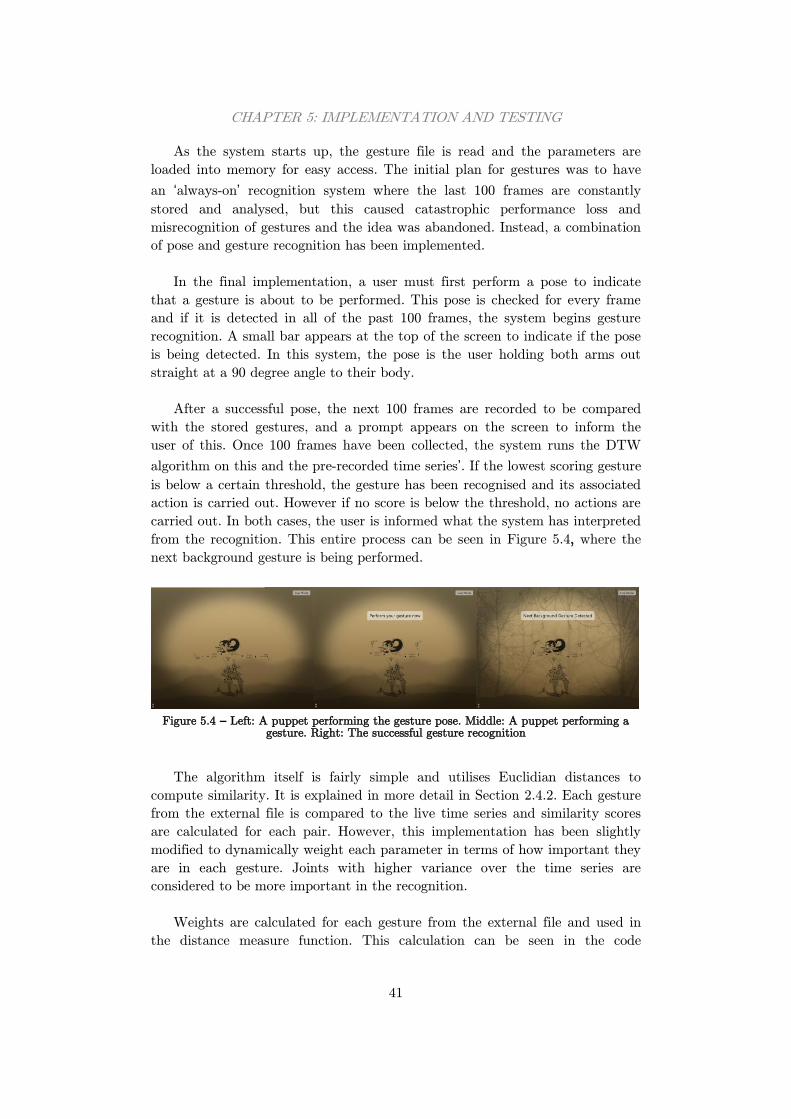
CHAPTER 5: IMPLEMENTATION AND TESTING
41
As the system starts up, the gesture file is read and the parameters are
loaded into memory for easy access. The initial plan for gestures was to have
an ‘always-on’ recognition system where the last 100 frames are constantly
stored and analysed, but this caused catastrophic performance loss and
misrecognition of gestures and the idea was abandoned. Instead, a combination
of pose and gesture recognition has been implemented.
In the final implementation, a user must first perform a pose to indicate
that a gesture is about to be performed. This pose is checked for every frame
and if it is detected in all of the past 100 frames, the system begins gesture
recognition. A small bar appears at the top of the screen to indicate if the pose
is being detected. In this system, the pose is the user holding both arms out
straight at a 90 degree angle to their body.
After a successful pose, the next 100 frames are recorded to be compared
with the stored gestures, and a prompt appears on the screen to inform the
user of this. Once 100 frames have been collected, the system runs the DTW
algorithm on this and the pre-recorded time series’. If the lowest scoring gesture
is below a certain threshold, the gesture has been recognised and its associated
action is carried out. However if no score is below the threshold, no actions are
carried out. In both cases, the user is informed what the system has interpreted
from the recognition. This entire process can be seen in Figure 5.4, where the
next background gesture is being performed.
Figure 5.4 – Left: A puppet performing the gesture pose. Middle: A puppet performing a
gesture. Right: The successful gesture recognition
The algorithm itself is fairly simple and utilises Euclidian distances to
compute similarity. It is explained in more detail in Section 2.4.2. Each gesture
from the external file is compared to the live time series and similarity scores
are calculated for each pair. However, this implementation has been slightly
modified to dynamically weight each parameter in terms of how important they
are in each gesture. Joints with higher variance over the time series are
considered to be more important in the recognition.
Weights are calculated for each gesture from the external file and used in
the distance measure function. This calculation can be seen in the code
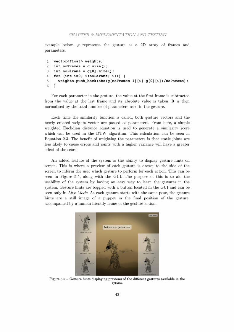
CHAPTER 5: IMPLEMENTATION AND TESTING
42
example below. g represents the gesture as a 2D array of frames and
parameters.
1
2
3
4
5
6
vector<float> weights;
int noFrames = g.size();
int noParams = g[0].size();
for (int i=0; i<noParams; i++) {
weights.push_back(abs(g[noFrames-1][i]-g[0][i])/noParams);
}
For each parameter in the gesture, the value at the first frame is subtracted
from the value at the last frame and its absolute value is taken. It is then
normalised by the total number of parameters used in the gesture.
Each time the similarity function is called, both gesture vectors and the
newly created weights vector are passed as parameters. From here, a simple
weighted Euclidian distance equation is used to generate a similarity score
which can be used in the DTW algorithm. This calculation can be seen in
Equation 2.3. The benefit of weighting the parameters is that static joints are
less likely to cause errors and joints with a higher variance will have a greater
effect of the score.
An added feature of the system is the ability to display gesture hints on
screen. This is where a preview of each gesture is drawn to the side of the
screen to inform the user which gesture to perform for each action. This can be
seen in Figure 5.5, along with the GUI. The purpose of this is to aid the
usability of the system by having an easy way to learn the gestures in the
system. Gesture hints are toggled with a button located in the GUI and can be
seen only in Live Mode. As each gesture starts with the same pose, the gesture
hints are a still image of a puppet in the final position of the gesture,
accompanied by a human friendly name of the gesture action.
Figure 5.5 – Gesture hints displaying previews of the different gestures available in the
system
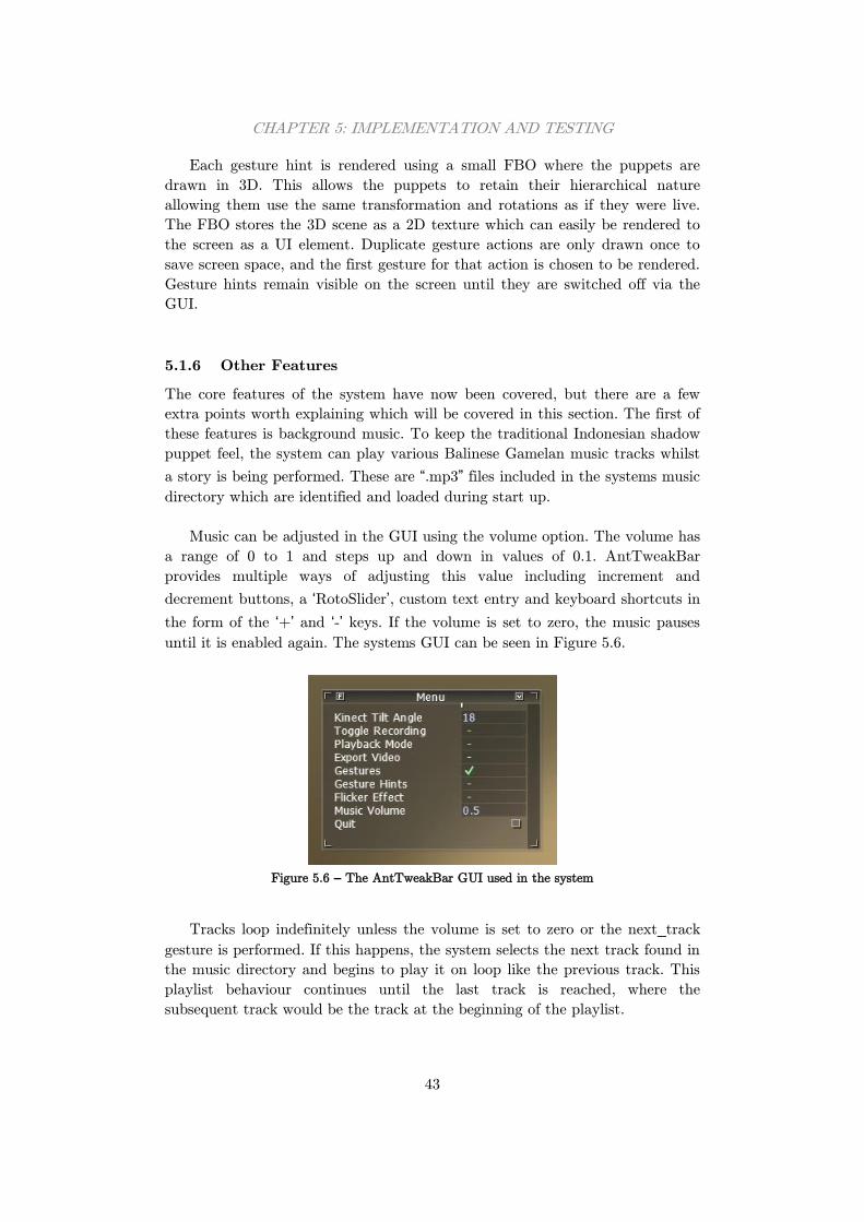
CHAPTER 5: IMPLEMENTATION AND TESTING
43
Each gesture hint is rendered using a small FBO where the puppets are
drawn in 3D. This allows the puppets to retain their hierarchical nature
allowing them use the same transformation and rotations as if they were live.
The FBO stores the 3D scene as a 2D texture which can easily be rendered to
the screen as a UI element. Duplicate gesture actions are only drawn once to
save screen space, and the first gesture for that action is chosen to be rendered.
Gesture hints remain visible on the screen until they are switched off via the
GUI.
5.1.6 Other Features
The core features of the system have now been covered, but there are a few
extra points worth explaining which will be covered in this section. The first of
these features is background music. To keep the traditional Indonesian shadow
puppet feel, the system can play various Balinese Gamelan music tracks whilst
a story is being performed. These are “.mp3” files included in the systems music
directory which are identified and loaded during start up.
Music can be adjusted in the GUI using the volume option. The volume has
a range of 0 to 1 and steps up and down in values of 0.1. AntTweakBar
provides multiple ways of adjusting this value including increment and
decrement buttons, a ‘RotoSlider’, custom text entry and keyboard shortcuts in
the form of the ‘+’ and ‘-’ keys. If the volume is set to zero, the music pauses
until it is enabled again. The systems GUI can be seen in Figure 5.6.
Figure 5.6 – The AntTweakBar GUI used in the system
Tracks loop indefinitely unless the volume is set to zero or the next_track
gesture is performed. If this happens, the system selects the next track found in
the music directory and begins to play it on loop like the previous track. This
playlist behaviour continues until the last track is reached, where the
subsequent track would be the track at the beginning of the playlist.
CHAPTER 5: IMPLEMENTATION AND TESTING
44
The system is designed so that any “.mp3” file found in the music directory
will be loaded and played in the playlist. This means that custom background
tracks can be added to the folder to create custom stories. This idea could also
be used to add narration tracks to stories which allow users to act out the story
as it is being described.
As music switching is controlled using gestures, any saved stories will retain
the intended behaviour, providing that music is already switched on and the
correct track for the story is already playing. However, music cannot be added
to exported videos as the QuickTime libraries included in Cinder do not
support audio output in videos. For music to be played with exported videos,
the video file must either be edited with external software to add an audio
track, or played at the same time as a music track. This downside is not ideal
but unavoidable without using an alternative video exporting library.
A smaller feature in the system is a flicker effect. This is designed to
simulate the light source, traditionally a candle, flickering behind the screen.
The flicker effect can be toggled with a button in the GUI, but is enabled by
default. The amount of flicker is calculated using a sin wave, which has added
noise generated by random numbers. This number is then applied to the alpha
channel of the background gradient, making it more or less transparent and
revealing more or less of the black background underneath. Although it is a
subtle effect, it adds to the realism of the application and makes stories more
believable.
5.2 Testing
Systems of a graphical nature are typically much harder to test than any other
type of system. Despite this, there are more concrete tests that can be
performed to evaluate the success of the system in other areas. The testing of
this system will look at each feature in turn, evaluating them in the most
appropriate way. This could include unit tests which are used to evaluate the
programming and find any errors or malfunctions in the written code, or they
could consist of system tests which compare the system to the requirements
specified in Section 3.1. The features which will be analysed include the gesture
recognition system and save file handling amongst many others.
As the system was built using an iterative and incremental development
technique as described in Section 4.1, testing occurred during the entirety of
the development process. This means that as new features and methods were
implemented into the system, they were tested and approved before any further
development commenced. This technique assumes that more bugs are
discovered and fixed earlier in the development process and as a result, fewer
bugs will carry through to the final testing phase where they may have
propagated to other areas of the system.
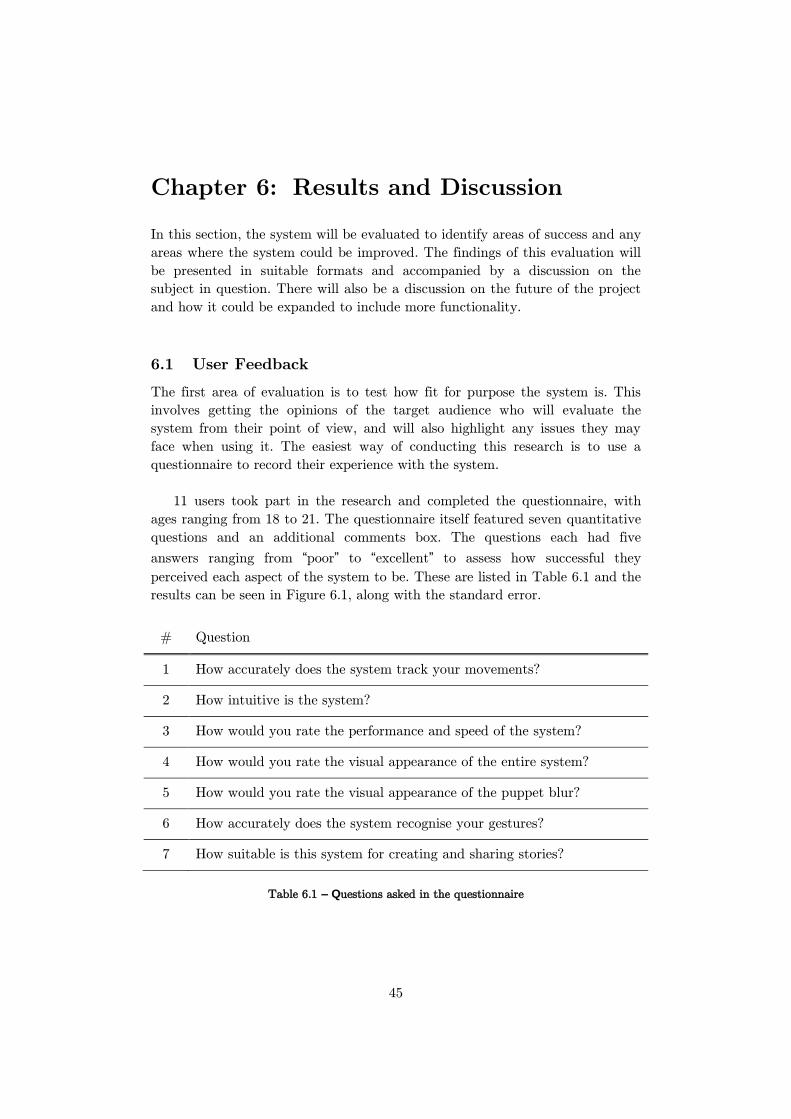
45
Chapter 6: Results and Discussion
In this section, the system will be evaluated to identify areas of success and any
areas where the system could be improved. The findings of this evaluation will
be presented in suitable formats and accompanied by a discussion on the
subject in question. There will also be a discussion on the future of the project
and how it could be expanded to include more functionality.
6.1 User Feedback
The first area of evaluation is to test how fit for purpose the system is. This
involves getting the opinions of the target audience who will evaluate the
system from their point of view, and will also highlight any issues they may
face when using it. The easiest way of conducting this research is to use a
questionnaire to record their experience with the system.
11 users took part in the research and completed the questionnaire, with
ages ranging from 18 to 21. The questionnaire itself featured seven quantitative
questions and an additional comments box. The questions each had five
answers ranging from “poor” to “excellent” to assess how successful they
perceived each aspect of the system to be. These are listed in Table 6.1 and the
results can be seen in Figure 6.1, along with the standard error.
# Question
1 How accurately does the system track your movements?
2 How intuitive is the system?
3 How would you rate the performance and speed of the system?
4 How would you rate the visual appearance of the entire system?
5 How would you rate the visual appearance of the puppet blur?
6 How accurately does the system recognise your gestures?
7 How suitable is this system for creating and sharing stories?
Table 6.1 – Questions asked in the questionnaire

CHAPTER 6: RESULTS AND DISCUSSION
46
Figure 6.1 – Graph visualising the average response for each question in the questionnaire
The responses from the questionnaire were highly positive with average
scores ranging from 75% to 93%. Test users agreed the system tracked their
movements accurately, that it was visually appealing and that the puppet blur
was aesthetically pleasing. However, the lowest scoring questions reveal that
they suggest the system could be more intuitive, that the storytelling aspect
could be improved and that the gesture recognition was not always accurate.
One test user suggested that the storytelling aspect could be improved with
the addition of narration or onscreen text. In the current system, there is no
easy way to add text or narration to a story. This is an excellent suggestion
and something which would greatly improve the user experience of the system.
Currently, narration can be added by pre-recording a voiceover audio track and
adding it to the music folder of the system. This can then play in the
background as the user acts out their story. Onscreen text is however not
possible in the current system as it would require a save file editor, and this
was outside the scope of the project.
Another test user noted that when playing back a story using the system,
the character and background may not always be the same as they were when
the story was first recorded. This is a valid point and this is due to the save
file. Currently, save files do not store information such as the starting puppet
and background; only the parameters used to display puppets. This missing
information means that the system does not know which puppet textures to use
and therefore defaults to what is currently selected, which may be incorrect. To
overcome this, additional information would need to be included in save files,
altering the design of the file and the way it is written to and read back.
0%
10%
20%
30%
40%
50%
60%
70%
80%
90%
100%
1 2 3 4 5 6 7
Avera
ge
Score
Question Number
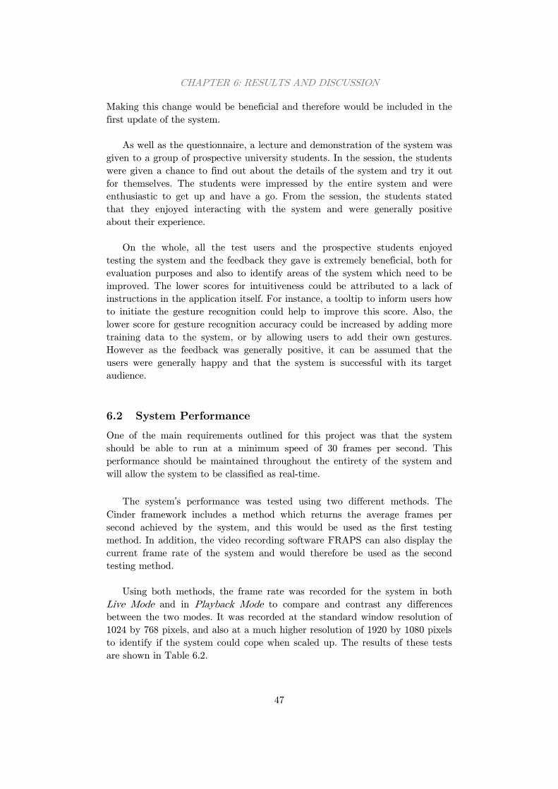
CHAPTER 6: RESULTS AND DISCUSSION
47
Making this change would be beneficial and therefore would be included in the
first update of the system.
As well as the questionnaire, a lecture and demonstration of the system was
given to a group of prospective university students. In the session, the students
were given a chance to find out about the details of the system and try it out
for themselves. The students were impressed by the entire system and were
enthusiastic to get up and have a go. From the session, the students stated
that they enjoyed interacting with the system and were generally positive
about their experience.
On the whole, all the test users and the prospective students enjoyed
testing the system and the feedback they gave is extremely beneficial, both for
evaluation purposes and also to identify areas of the system which need to be
improved. The lower scores for intuitiveness could be attributed to a lack of
instructions in the application itself. For instance, a tooltip to inform users how
to initiate the gesture recognition could help to improve this score. Also, the
lower score for gesture recognition accuracy could be increased by adding more
training data to the system, or by allowing users to add their own gestures.
However as the feedback was generally positive, it can be assumed that the
users were generally happy and that the system is successful with its target
audience.
6.2 System Performance
One of the main requirements outlined for this project was that the system
should be able to run at a minimum speed of 30 frames per second. This
performance should be maintained throughout the entirety of the system and
will allow the system to be classified as real-time.
The system’s performance was tested using two different methods. The
Cinder framework includes a method which returns the average frames per
second achieved by the system, and this would be used as the first testing
method. In addition, the video recording software FRAPS can also display the
current frame rate of the system and would therefore be used as the second
testing method.
Using both methods, the frame rate was recorded for the system in both
Live Mode and in Playback Mode to compare and contrast any differences
between the two modes. It was recorded at the standard window resolution of
1024 by 768 pixels, and also at a much higher resolution of 1920 by 1080 pixels
to identify if the system could cope when scaled up. The results of these tests
are shown in Table 6.2.
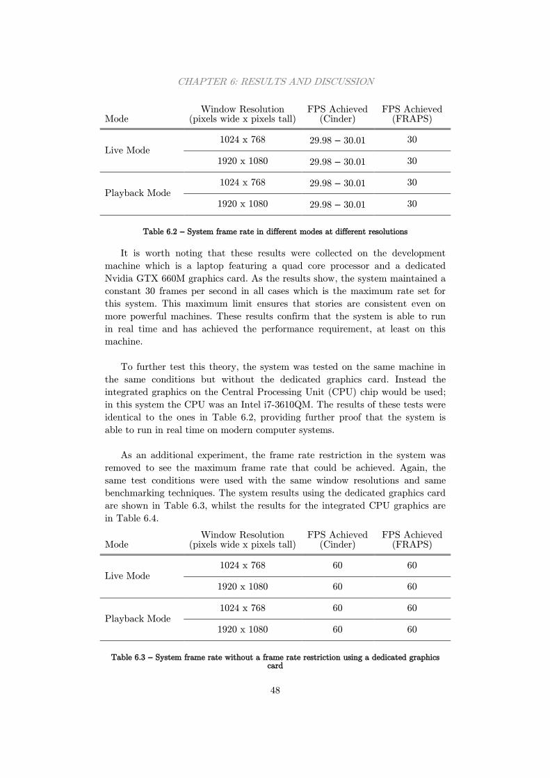
CHAPTER 6: RESULTS AND DISCUSSION
48
Mode Window Resolution
(pixels wide x pixels tall) FPS Achieved
(Cinder) FPS Achieved
(FRAPS)
Live Mode 1024 x 768 29.98 – 30.01 30
1920 x 1080 29.98 – 30.01 30
Playback Mode 1024 x 768 29.98 – 30.01 30
1920 x 1080 29.98 – 30.01 30
Table 6.2 – System frame rate in different modes at different resolutions
It is worth noting that these results were collected on the development
machine which is a laptop featuring a quad core processor and a dedicated
Nvidia GTX 660M graphics card. As the results show, the system maintained a
constant 30 frames per second in all cases which is the maximum rate set for
this system. This maximum limit ensures that stories are consistent even on
more powerful machines. These results confirm that the system is able to run
in real time and has achieved the performance requirement, at least on this
machine.
To further test this theory, the system was tested on the same machine in
the same conditions but without the dedicated graphics card. Instead the
integrated graphics on the Central Processing Unit (CPU) chip would be used;
in this system the CPU was an Intel i7-3610QM. The results of these tests were
identical to the ones in Table 6.2, providing further proof that the system is
able to run in real time on modern computer systems.
As an additional experiment, the frame rate restriction in the system was
removed to see the maximum frame rate that could be achieved. Again, the
same test conditions were used with the same window resolutions and same
benchmarking techniques. The system results using the dedicated graphics card
are shown in Table 6.3, whilst the results for the integrated CPU graphics are
in Table 6.4.
Mode Window Resolution
(pixels wide x pixels tall) FPS Achieved
(Cinder) FPS Achieved
(FRAPS)
Live Mode 1024 x 768 60 60
1920 x 1080 60 60
Playback Mode 1024 x 768 60 60
1920 x 1080 60 60
Table 6.3 – System frame rate without a frame rate restriction using a dedicated graphics card
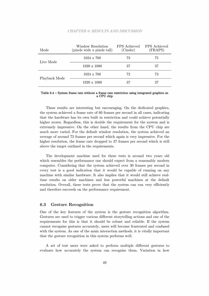
CHAPTER 6: RESULTS AND DISCUSSION
49
Mode Window Resolution
(pixels wide x pixels tall) FPS Achieved
(Cinder) FPS Achieved
(FRAPS)
Live Mode 1024 x 768 73 75
1920 x 1080 37 37
Playback Mode 1024 x 768 72 73
1920 x 1080 37 37
Table 6.4 – System frame rate without a frame rate restriction using integrated graphics on a CPU chip
These results are interesting but encouraging. On the dedicated graphics,
the system achieved a frame rate of 60 frames per second in all cases, indicating
that the hardware has its own built in restriction and could achieve potentially
higher scores. Regardless, this is double the requirement for the system and is
extremely impressive. On the other hand, the results from the CPU chip are
much more varied. For the default window resolution, the system achieved an
average of around 73 frames per second which again is very impressive. For the
higher resolution, the frame rate dropped to 37 frames per second which is still
above the target outlined in the requirements.
The development machine used for these tests is around two years old
which resembles the performance one should expect from a reasonably modern
computer. Considering that the system achieved over 30 frames per second in
every test is a good indication that it would be capable of running on any
machine with similar hardware. It also implies that it would still achieve real-
time results on older machines and less powerful machines at the default
resolution. Overall, these tests prove that the system can run very efficiently
and therefore succeeds on the performance requirement.
6.3 Gesture Recognition
One of the key features of the system is the gesture recognition algorithm.
Gestures are used to trigger various different storytelling actions and one of the
requirements for this is that it should be robust and reliable. If the system
cannot recognise gestures accurately, users will become frustrated and confused
with the system. As one of the main interaction methods, it is vitally important
that the gesture recognition in this system performs well.
A set of test users were asked to perform multiple different gestures to
evaluate how accurately the system can recognise them. Variation in how
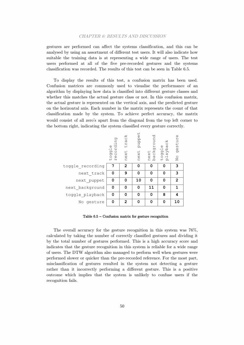
CHAPTER 6: RESULTS AND DISCUSSION
50
gestures are performed can affect the systems classification, and this can be
analysed by using an assortment of different test users. It will also indicate how
suitable the training data is at representing a wide range of users. The test
users performed at all of the five pre-recorded gestures and the systems
classification was recorded. The results of this test can be seen in Table 6.5.
To display the results of this test, a confusion matrix has been used.
Confusion matrices are commonly used to visualise the performance of an
algorithm by displaying how data is classified into different gesture classes and
whether this matches the actual gesture class or not. In this confusion matrix,
the actual gesture is represented on the vertical axis, and the predicted gesture
on the horizontal axis. Each number in the matrix represents the count of that
classification made by the system. To achieve perfect accuracy, the matrix
would consist of all zero’s apart from the diagonal from the top left corner to
the bottom right, indicating the system classified every gesture correctly.
toggle
recording
next track
next puppet
next
background
toggle
playback
No gesture
toggle_recording 7 2 0 0 0 3
next_track 0 9 0 0 0 3
next_puppet 0 0 10 0 0 2
next_background 0 0 0 11 0 1
toggle_playback 0 0 0 0 8 4
No gesture 0 2 0 0 0 10
Table 6.5 – Confusion matrix for gesture recognition
The overall accuracy for the gesture recognition in this system was 76%,
calculated by taking the number of correctly classified gestures and dividing it
by the total number of gestures performed. This is a high accuracy score and
indicates that the gesture recognition in this system is reliable for a wide range
of users. The DTW algorithm also managed to perform well when gestures were
performed slower or quicker than the pre-recorded reference. For the most part,
misclassification of gestures resulted in the system not detecting a gesture
rather than it incorrectly performing a different gesture. This is a positive
outcome which implies that the system is unlikely to confuse users if the
recognition fails.
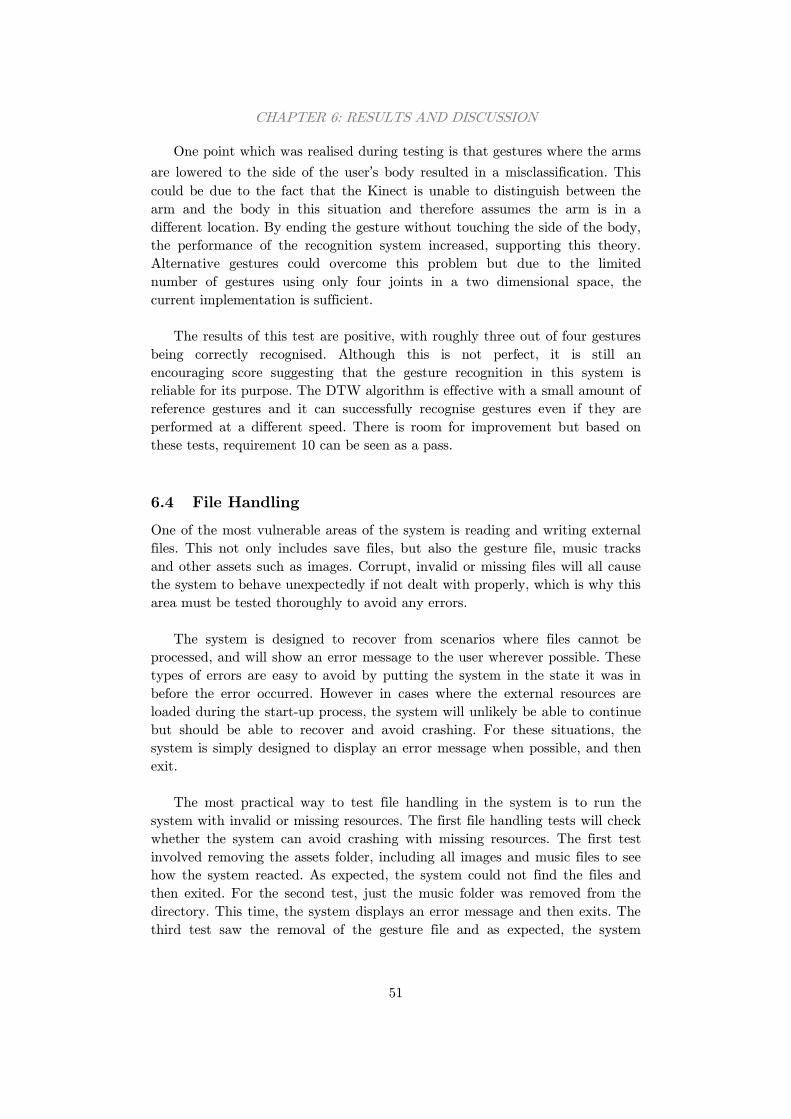
CHAPTER 6: RESULTS AND DISCUSSION
51
One point which was realised during testing is that gestures where the arms
are lowered to the side of the user’s body resulted in a misclassification. This
could be due to the fact that the Kinect is unable to distinguish between the
arm and the body in this situation and therefore assumes the arm is in a
different location. By ending the gesture without touching the side of the body,
the performance of the recognition system increased, supporting this theory.
Alternative gestures could overcome this problem but due to the limited
number of gestures using only four joints in a two dimensional space, the
current implementation is sufficient.
The results of this test are positive, with roughly three out of four gestures
being correctly recognised. Although this is not perfect, it is still an
encouraging score suggesting that the gesture recognition in this system is
reliable for its purpose. The DTW algorithm is effective with a small amount of
reference gestures and it can successfully recognise gestures even if they are
performed at a different speed. There is room for improvement but based on
these tests, requirement 10 can be seen as a pass.
6.4 File Handling
One of the most vulnerable areas of the system is reading and writing external
files. This not only includes save files, but also the gesture file, music tracks
and other assets such as images. Corrupt, invalid or missing files will all cause
the system to behave unexpectedly if not dealt with properly, which is why this
area must be tested thoroughly to avoid any errors.
The system is designed to recover from scenarios where files cannot be
processed, and will show an error message to the user wherever possible. These
types of errors are easy to avoid by putting the system in the state it was in
before the error occurred. However in cases where the external resources are
loaded during the start-up process, the system will unlikely be able to continue
but should be able to recover and avoid crashing. For these situations, the
system is simply designed to display an error message when possible, and then
exit.
The most practical way to test file handling in the system is to run the
system with invalid or missing resources. The first file handling tests will check
whether the system can avoid crashing with missing resources. The first test
involved removing the assets folder, including all images and music files to see
how the system reacted. As expected, the system could not find the files and
then exited. For the second test, just the music folder was removed from the
directory. This time, the system displays an error message and then exits. The
third test saw the removal of the gesture file and as expected, the system
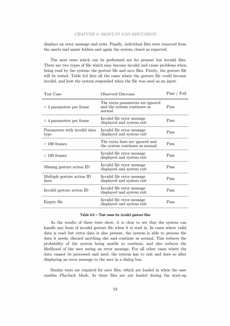
CHAPTER 6: RESULTS AND DISCUSSION
52
displays an error message and exits. Finally, individual files were removed from
the assets and music folders and again the system closed as expected.
The next tests which can be performed are for present but invalid files.
There are two types of file which may become invalid and cause problems when
being read by the system: the gesture file and save files. Firstly, the gesture file
will be tested. Table 6.6 lists all the cases where the gesture file could become
invalid, and how the system responded when the file was used as an input.
Test Case Observed Outcome Pass / Fail
> 4 parameters per frame The extra parameters are ignored and the system continues as normal
Pass
< 4 parameters per frame Invalid file error message displayed and system exit
Pass
Parameters with invalid data type
Invalid file error message displayed and system exit
Pass
> 100 frames The extra lines are ignored and the system continues as normal
Pass
< 100 frames Invalid file error message displayed and system exit
Pass
Missing gesture action ID Invalid file error message displayed and system exit
Pass
Multiple gesture action ID lines
Invalid file error message displayed and system exit
Pass
Invalid gesture action ID Invalid file error message displayed and system exit
Pass
Empty file Invalid file error message displayed and system exit
Pass
Table 6.6 – Test cases for invalid gesture files
As the results of these tests show, it is clear to see that the system can
handle any form of invalid gesture file when it is read in. In cases where valid
data is read but extra data is also present, the system is able to process the
data it needs, discard anything else and continue as normal. This reduces the
probability of the system being unable to continue, and also reduces the
likelihood of the user seeing an error message. For all other cases where the
data cannot be processed and used, the system has to exit and does so after
displaying an error message to the user in a dialog box.
Similar tests are required for save files, which are loaded in when the user
enables Playback Mode. As these files are not loaded during the start-up
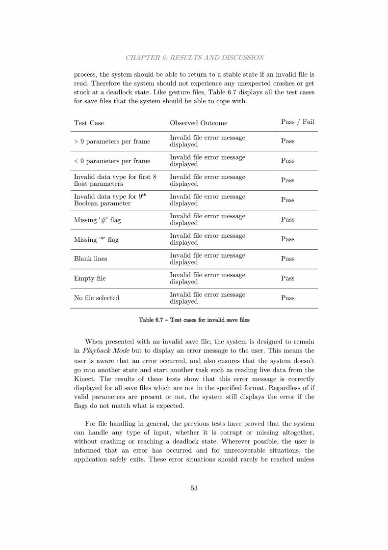
CHAPTER 6: RESULTS AND DISCUSSION
53
process, the system should be able to return to a stable state if an invalid file is
read. Therefore the system should not experience any unexpected crashes or get
stuck at a deadlock state. Like gesture files, Table 6.7 displays all the test cases
for save files that the system should be able to cope with.
Test Case Observed Outcome Pass / Fail
> 9 parameters per frame Invalid file error message displayed
Pass
< 9 parameters per frame Invalid file error message displayed
Pass
Invalid data type for first 8 float parameters
Invalid file error message displayed
Pass
Invalid data type for 9th Boolean parameter
Invalid file error message displayed
Pass
Missing ‘#’ flag Invalid file error message displayed
Pass
Missing ‘*’ flag Invalid file error message displayed
Pass
Blank lines Invalid file error message displayed
Pass
Empty file Invalid file error message displayed
Pass
No file selected Invalid file error message displayed
Pass
Table 6.7 – Test cases for invalid save files
When presented with an invalid save file, the system is designed to remain
in Playback Mode but to display an error message to the user. This means the
user is aware that an error occurred, and also ensures that the system doesn’t
go into another state and start another task such as reading live data from the
Kinect. The results of these tests show that this error message is correctly
displayed for all save files which are not in the specified format. Regardless of if
valid parameters are present or not, the system still displays the error if the
flags do not match what is expected.
For file handling in general, the previous tests have proved that the system
can handle any type of input, whether it is corrupt or missing altogether,
without crashing or reaching a deadlock state. Wherever possible, the user is
informed that an error has occurred and for unrecoverable situations, the
application safely exits. These error situations should rarely be reached unless
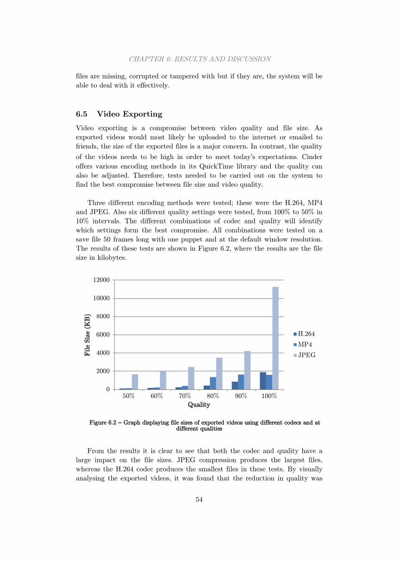
CHAPTER 6: RESULTS AND DISCUSSION
54
files are missing, corrupted or tampered with but if they are, the system will be
able to deal with it effectively.
6.5 Video Exporting
Video exporting is a compromise between video quality and file size. As
exported videos would most likely be uploaded to the internet or emailed to
friends, the size of the exported files is a major concern. In contrast, the quality
of the videos needs to be high in order to meet today’s expectations. Cinder
offers various encoding methods in its QuickTime library and the quality can
also be adjusted. Therefore, tests needed to be carried out on the system to
find the best compromise between file size and video quality.
Three different encoding methods were tested; these were the H.264, MP4
and JPEG. Also six different quality settings were tested, from 100% to 50% in
10% intervals. The different combinations of codec and quality will identify
which settings form the best compromise. All combinations were tested on a
save file 50 frames long with one puppet and at the default window resolution.
The results of these tests are shown in Figure 6.2, where the results are the file
size in kilobytes.
Figure 6.2 – Graph displaying file sizes of exported videos using different codecs and at
different qualities
From the results it is clear to see that both the codec and quality have a
large impact on the file sizes. JPEG compression produces the largest files,
whereas the H.264 codec produces the smallest files in these tests. By visually
analysing the exported videos, it was found that the reduction in quality was
0
2000
4000
6000
8000
10000
12000
50% 60% 70% 80% 90% 100%
File S
ize (
KB
)
Quality
H.264
MP4
JPEG
CHAPTER 6: RESULTS AND DISCUSSION
55
only noticeable at and below 70%. Enabling the flicker effect makes this even
more apparent.
The quality is therefore to be set halfway between 70% and 80% to ensure
that the reduction in quality is barely noticeable and that the file size can
remain as small as possible. The visual difference between H.264 and MP4 was
also insignificant so based on the results collected, the best compression method
to use in this system is the H.264 codec. These are the settings that have been
implemented into the system, providing the best possible balance between file
size and quality.
6.6 Requirements Evaluation
The most important area of system testing is the requirements evaluation. This
is where the system is compared to the requirements outlined in Section 3.1 to
identify which areas were completed and which areas were not. Using this can
help to evaluate how successful the system has been in terms of the quality of
the programming and the user acceptability. These requirements and the
results of this evaluation can be seen in Table 6.8.
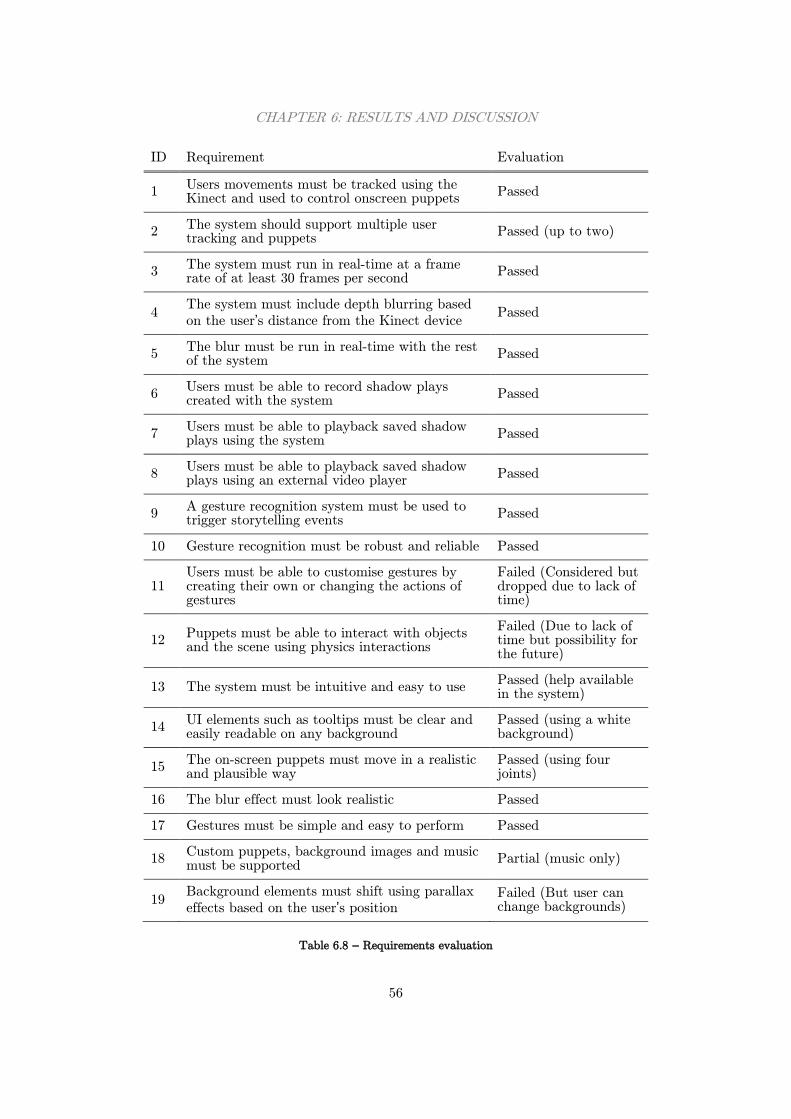
CHAPTER 6: RESULTS AND DISCUSSION
56
ID Requirement Evaluation
1 Users movements must be tracked using the Kinect and used to control onscreen puppets
Passed
2 The system should support multiple user tracking and puppets
Passed (up to two)
3 The system must run in real-time at a frame rate of at least 30 frames per second
Passed
4 The system must include depth blurring based
on the user’s distance from the Kinect device Passed
5 The blur must be run in real-time with the rest of the system
Passed
6 Users must be able to record shadow plays created with the system
Passed
7 Users must be able to playback saved shadow plays using the system
Passed
8 Users must be able to playback saved shadow plays using an external video player
Passed
9 A gesture recognition system must be used to trigger storytelling events
Passed
10 Gesture recognition must be robust and reliable Passed
11 Users must be able to customise gestures by creating their own or changing the actions of gestures
Failed (Considered but dropped due to lack of time)
12 Puppets must be able to interact with objects and the scene using physics interactions
Failed (Due to lack of time but possibility for the future)
13 The system must be intuitive and easy to use Passed (help available in the system)
14 UI elements such as tooltips must be clear and easily readable on any background
Passed (using a white background)
15 The on-screen puppets must move in a realistic and plausible way
Passed (using four joints)
16 The blur effect must look realistic Passed
17 Gestures must be simple and easy to perform Passed
18 Custom puppets, background images and music must be supported
Partial (music only)
19 Background elements must shift using parallax
effects based on the user’s position Failed (But user can change backgrounds)
Table 6.8 – Requirements evaluation
CHAPTER 6: RESULTS AND DISCUSSION
57
From this evaluation it is clear to see that the majority of tasks have been
completed successfully. Only 3 out of the 19 requirements were not
accomplished due to a lack of time in the project, and these three requirements
were all optional. This means that all the essential and desirable requirements
have been achieved and that the system has fulfils its original purpose.
Therefore it can be regarded as a success in this area.
6.7 Further Work
Although the system has been largely successful, there are still areas where it
could be improved. Future work developing the system would allow for many
extra features including ones which were just outside the scope of this project.
One of the main areas for improvement as noted by one test user is
narration or captions for stories. In the current system, stories consist of
characters moving around the screen with accompanying music, but no actual
story is told. Whilst many traditional Wayang Kulit performances tell stories
this way, narration in the form of recorded audio or onscreen captions at key
points in the story would greatly enhance the storytelling experience for the
user.
On the other hand, adding captions would require a story editor which
allowed the user to add strings of text at key points of the story. This editor
could also be given the ability to trim and rearrange parts of stories to create a
larger, more complex story. Again this was considered, but ultimately dropped
due to the advanced stage the project had reached.
Similar to the story editor, a gesture editor could be implemented into the
system. This would be used to modify gesture files and allow new gestures to
be added, tailoring the system for that particular user. However, there is added
complexity to this as new gestures may be incompatible with the current DTW
setup, and the user would need to adjust the gesture recognition threshold to
ensure that the system is at the correct sensitivity. Leaving this threshold
untouched could mean that the gesture recognition algorithm may not detect
all custom gestures.
The gestures in this system are designed to be easily recognised by the
Kinect and the recognition algorithm and modifying the existing gestures may
cause the application to become less responsive, so a reset function would also
be required. Much like the other features, this gesture editor would have taken
too much time to implement and was not considered in this project.
Audio recording was investigated during this project for video exporting
but it was found that the QuickTime library used to export stories as video
CHAPTER 6: RESULTS AND DISCUSSION
58
files did not support audio output. This meant that the whole video recording
system would need to be redesigned using a different library to allow audio
tracks to be stored in the video file, and this was unfortunately outside the
scope of the project. In the future, the system could be updated to use a
different video exporting library that supports audio output.
Finally a more advanced feature which could be added is interactive
objects. The ability for users to spawn in objects and manipulate them with the
puppets would greatly increase the appeal of the system. The objects could also
be physics-based, interacting with the window with effects such as bouncing.
Objects and animals do appear in traditional shadow puppet shows and would
be a worthwhile addition to the system, but due to the time required to
implement such a feature, this addition never advanced beyond just an idea.
These are just a few ways the system could be expanded, and there are
surely many more areas which could be improved in time. For instance the
system performance could be improved on less powerful systems and the code
could be generally optimised. However given the time constraints of this
project, the system has managed to accomplish the requirements set at the
beginning and therefore has fulfilled its purpose.
59
Chapter 7: Conclusions
The goal of this project was to build a real-time shadow puppet storytelling
application using the Microsoft Kinect sensor. The project began with initial
research into all the areas that would be covered in the project. This included
general research into Indonesian shadow puppetry, the Kinect sensor and how
it can be used for systems such as this one, image processing techniques which
allow effects such as blurring, and also how gesture recognition can be
implemented using efficient and reliable algorithms.
This research revealed many techniques which could be used in this system
so the next step was to create a formal list of system requirements. These
would be used to keep the project development on track and to evaluate the
system later on. The project was also to follow the iterative and incremental
development model which would enforce continual testing and short
development cycles.
There were two options for which programming language to create the
system in, and these were Java and C++. Both languages would also be
accompanied by a graphical framework; for Java, the Processing framework
would be used and for C++, the Cinder framework. Based on the performance
advantages of C++ and the real-time requirements of the project, C++ and
Cinder were chosen for the systems development. As a Java programmer, this
presented its own challenge and there was a steep learning curve adapting to
the new language and setting up the environment.
Implementing the system began as soon as possible. Using the KinectSDK
Cinder Block, a basic skeleton tracking application was developed and shortly
after, puppets were attached to the joints and bones of the skeletons. The basic
functionality of the system was achieved. From here, the real-time blur effect
would be implemented next.
From the multiple blurring algorithms, a two-pass Gaussian blur was
chosen. This was for its efficiency in real-time applications and its visually
appealing results. However to achieve two passes, the puppet must be rendered
to an intermediate texture. OpenGL includes FBO’s which provide this exact
functionality and with this in combination with OpenGL shaders, the blur
algorithm was in effect. The final step was to take the depth value and modify
the blur’s neighbourhood size accordingly.
Saving stories was the next step. By designing a file format to store
parameters in, it was simple to implement a basic recording and playback

CHAPTER 7: CONCLUSIONS
60
feature using C++’s file stream libraries. The difficulties in this area revolved
around error checking and playback. As the system needed to be robust, a lot
of work went into testing file validation to ensure the system did not crash due
to invalid file inputs. Given Cinder includes the QuickTime library, video
exporting was also introduced. However, instead of exporting live data from the
Kinect as planned, the system converts saved stories into video files. This was
due to performance issues faced with real-time video exporting.
The last major feature to implement was gesture recognition. A DTW
algorithm was chosen and various reference gestures were created. The initial
plan was to store every live frame and for each one, run the algorithm against
every stored gesture. This was incredibly inefficient and an alternative method
was devised. Users now have to perform an initial pose to indicate they are
about to perform a gesture, and the following frames are stored and compared.
This is much more efficient than the initial implementation which is vital
consideration in a real-time system.
Various tests were performed on each aspect of the system including both
unit and system tests. A requirements evaluation was also conducted to see
how well the system achieves its purpose. On the whole, the system was
received very well and passed the majority of the tests performed. This
indicated that the system is very robust and that users found it easy to
navigate around the features and enjoyed using the system.
Overall, the system that has been developed has fulfilled its purpose and
the project has been largely successful. Test users agree that the Indonesian
style is visually appealing and that there are many storytelling capabilities
included. However, they also pointed out that gesture recognition is a weak
area that could be improved. There is much room for expansion in the system
such as implementing interactive objects or supporting custom gestures,
something which could improve the existing gesture support. Due to time
constraints, these were unfortunately out of the scope of this project but could
be added to the system in the future.
61
References
Anon., 2006. ANALOG DEVICES AND NINTENDO COLLABORATION
DRIVES VIDEO GAME INNOVATION WITH IMEMS MOTION SIGNAL
PROCESSING TECHNOLOGY. [Online]
Available at: http://www.analog.com/en/press-
release/May_09_2006_ADI_Nintendo_Collaboration/press.html
[Accessed 6 December 2013].
Anon., 2010. PrimeSense Supplies 3-D-Sensing Technology to “Project
Natal” for Xbox 360. [Online]
Available at: http://www.microsoft.com/en-us/news/press/2010/mar10/03-
31primesensepr.aspx
[Accessed 26 November 2013].
Anon., n.d. About Cinder. [Online]
Available at: http://libcinder.org/about
[Accessed 28 November 2013].
Anon., n.d. About openFrameworks. [Online]
Available at: http://www.openframeworks.cc/about
[Accessed 28 November 2013].
Anon., n.d. AntTweakBar. [Online]
Available at: anttweakbar.sourceforge.net/doc/
[Accessed 1 April 2014].
Anon., n.d. Kinect for Windows features. [Online]
Available at: http://www.microsoft.com/en-
us/kinectforwindows/discover/features.aspx
[Accessed 26 November 2013].
Anon., n.d. OpenGL Overview. [Online]
Available at: http://www.opengl.org/about
[Accessed 28 November 2013].
Anon., n.d. Overview. A short introduction to the Processing software and
projects from the community.. [Online]
Available at: http://www.processing.org/overview
[Accessed 28 November 2013].
62
Anon., n.d. PrimeSense NITE. [Online]
Available at: http://www.openni.org/files/nite
[Accessed 27 November 2013].
Anon., n.d. PrimeSense Technology. [Online]
Available at: http://www.primesense.com/solutions/technology
[Accessed 26 November 2013].
Anon., n.d. Wayang Kulit of Indonesia. [Online]
Available at: http://www.balibeyond.com/wayang.html
[Accessed 1 December 2013].
Beaumont, C., 2009. E3 2009: Project Natal hands-on preview. [Online]
Available at: http://www.telegraph.co.uk/technology/e3-2009/5437978/E3-
2009-Project-Natal-hands-on-preview.html
[Accessed 26 November 2013].
Beck, K., 2001. Manifesto for Agile Software Development. [Online]
Available at: agilemanifesto.org
[Accessed 20 April 2014].
Cockburn, A., 2008. Using Both Incremental and Iterative Development.
STSC CrossTalk (USAF Software Technology Support Center), 21(5), pp. 27-
30.
Gavrila, D. & Davis, L., 1995. Towards 3-D model-based tracking and
recognition of human movement: a multi-view approach. s.l.:International
Workshop on automatic face-and gesture-recognition.
Horn, B., 1986. Robot Vision. s.l.:MIT Presss.
Isaac, M. & Paczkowski, J., 2013. Apple Confirms Acquisition of 3-D
Sensor Startup PrimeSense. [Online]
Available at: http://allthingsd.com/20131124/apple-confirms-acquisition-of-3d-
sensor-startup-primesense/
[Accessed 26 November 2013].
Kang, J.-w., Seo, D.-j. & Jung, D.-s., 2011. A Study on the control Method
of 3-Dimensional Space Application using KINECT System. IJCSNS
International Journal of Computer Science and Network Security, 11(9), pp.
55-59.
Kraft, C., 2010. Open Source Kinect contest has been won. [Online]
Available at: http://hackaday.com/2010/11/11/open-source-kinect-contest-has-
been-won/
[Accessed 27 November 2013].
63
Kumar, M., 2009. Develop 2009: SCEE’s Hirani Reveals PS Eye Facial
Recognition, Motion Controller Details. [Online]
Available at: http://www.gamasutra.com/php-
bin/news_index.php?story=24456
[Accessed 6 December 2013].
Lee, S., Jounghyun Kim, G. & Choi, S., 2009. Real-Time Depth-of-Field
Rendering Using Anisotropically Filtered Mipmap Interpolation. Visualization
and Computer Graphics, IEEE Transactions on, 15(3), pp. 453-464.
Leyvand, T. et al., 2011. Kinect Identity: Technology and Experience, s.l.:
IEEE Computer Society.
Long, R., 1982. Javanese shadow theatre: movement and characterization in
Ngayogyakarta wayang kulit. s.l.:Ann Arbor, Mich.: UMI Research Press.
Miller, M. J., 2011. PrimeSense: Motion Control Beyond the Kinect.
[Online]
Available at: http://forwardthinking.pcmag.com/gadgets/282321-primesense-
motion-control-beyond-the-kinect
[Accessed 26 November 2013].
Mitchell, R., 2010. PrimeSense releases open source drivers, middleware
that work with Kinect. [Online]
Available at: http://www.joystiq.com/2010/12/10/primesense-releases-open-
source-drivers-middleware-for-kinect/
[Accessed 27 November 2013].
O'Brien, T., n.d. Microsoft's new Kinect is official: larger field of view, HD
camera, wake with voice. [Online]
Available at: http://www.engadget.com/2013/05/21/microsofts-new-kinect-is-
official/
[Accessed 26 November 2013].
Press, W. H., Flannery, B. P., Teukolsky, S. A. & Vetterling, W. T., 1989.
Numerical Recipes in Pascal. 1st ed. s.l.:Cambridge University Press.
Reyes, M., Gabriel, D. & Sergio, E., 2011. Feature Weighting in Dynamic
Time Warping for Gesture Recognition in Depth Data. Computer Vision
Workshops (ICCV Workshops), 2011 IEEE International Conference on, pp.
1182-1188.
Russ, J. C., 2006. The Image Processing Handbook. s.l.:CRC press.
64
Schielberl, S., 2011. KinectSdk for Cinder. [Online]
Available at: http://www.bantherewind.com/kinectsdk-for-cinder
[Accessed 27 November 2013].
Silbert, S., n.d. Microsoft: next-gen Kinect sensor for Windows to launch in
2014. [Online]
Available at: http://www.engadget.com/2013/05/23/microsoft-next-gen-kinect-
sensor-for-windows-launch-in-2014/
[Accessed 26 November 2013].
Sonka, M., Hlavac, V. & Boyle, R., 1999. Image Processing, Analysis, and
Machine Vision. s.l.:s.n.
Starner, T. E., 1995. Visual Recognition of American Sign Language Using
Hidden Markov Models, s.l.: Massachusetts Inst of Tech Cambridge Dept of
Brain and Cognitive Sciences.
Visnjic, F., 2012. Puppet Parade. [Online]
Available at: http://www.creativeapplications.net/openframeworks/puppet-
parade-openframeworks/]
[Accessed 28 November 2013].
Warade, S., Aghav, J., Claude, P. & Udayagiri, S., 2012. Real-Time
Detection and Tracking with Kinect, Bangkok: Intl. Conf. Comp. Info. Tech..
Zeng, W., 2012. Microsoft Kinect Sensor and Its Effect, s.l.: IEEE
Multimedia.
65
Table of Figures
Figure 2.1 – A shadow puppet theatre setup ...................................................... 3
Figure 2.2 – Wayang Kulit shadow puppets ....................................................... 4
Figure 2.3 – PrimeSense’s depth sensing technology explained .......................... 6
Figure 2.4 – The Kinect skeletal tracking pipeline .............................................. 9
Figure 2.5 – A two dimensional plot of a Gaussian function ............................ 12
Figure 2.6 – From left to right: Original image, Image with box blur, Image
with Gaussian blur ............................................................................................. 13
Figure 2.7 – A dynamic time warping grid visualising two time sequences and
the shortest distance path between them .......................................................... 15
Figure 2.8 – Two time sequences with their Euclidian and dynamic time
warped distance measures at each point in time ............................................... 16
Figure 4.1 – Flow Diagram of the system ......................................................... 25
Figure 4.2 – Flow Diagram of the Render FBO function ................................. 26
Figure 4.3 – Mock-up of the application window in Live Mode ........................ 28
Figure 5.1 – The three puppet textures used for Puppet 1 ............................... 33
Figure 5.2 – Graph visualising the Gaussian filter kernel used in the system .. 36
Figure 5.3 – A puppet in normal and blurred states ......................................... 37
Figure 5.4 – Left: A puppet performing the gesture pose. Middle: A puppet
performing a gesture. Right: The successful gesture recognition ....................... 41
Figure 5.5 – Gesture hints displaying previews of the different gestures
available in the system ...................................................................................... 42
Figure 5.6 – The AntTweakBar GUI used in the system ................................. 43
Figure 6.1 – Graph visualising the average response for each question in the
questionnaire ...................................................................................................... 46
Figure 6.2 – Graph displaying file sizes of exported videos using different
codecs and at different qualities ........................................................................ 54