SH 3964 EN - Samson AG
20
SH 3964 EN Translation of original instructions Type 3964 Solenoid Pilot Valve with and without CNOMO adapter plate Edition October 2021 Type 3964 Solenoid Pilot Valve
Transcript of SH 3964 EN - Samson AG

SH 3964 EN
Translation of original instructions
Type 3964 Solenoid Pilot Valve with and without CNOMO adapter plate
Edition October 2021
Type 3964 Solenoid Pilot Valve

Definition of signal words
Hazardous situations which, if not avoided, will result in death or serious injury
Hazardous situations which, if not avoided, could result in death or serious injury
Property damage message or malfunction
Additional information
Recommended action
DANGER!
WARNING!
NOTICE!
Note
Tip
2 SH 3964 EN

SH 3964 EN 3
Purpose of this manualThe Safety Manual SH 3964 contains information relevant for the use of the Type 3964 Sole-noid Pilot Valve in safety-instrumented systems according to IEC 61508 and IEC 61511. The safety manual is intended for planners, constructors and operators of safety-instrumented systems.
Risk of malfunction due to incorrect mounting, connection or start-up of the solenoid pilot valve.Refer to the Mounting and Operating Instructions EB 3964 on how to mount the device, per-form the electric and pneumatic connections as well as start up the device.
Î Observe the warnings and safety instructions written in the Mounting and Operating In-structions EB 3964.
Further documentationThe documents listed below contain descriptions of the start-up, functioning and operation of the limit switch. You can download these documents from the SAMSON website.u T 3964: Data sheetu EB 3964: Mounting and operating instructions
In addition to the solenoid pilot valve documentation, observe the technical documentation for the pneumatic actuator, control valve and other valve accessories.
NOTICE!
Note

Contents
4 SH 3964 EN
1 Scope ...........................................................................................................51.1 General ........................................................................................................51.2 Use in safety-instrumented systems ..................................................................51.3 Versions and ordering data ............................................................................52 Mounting ......................................................................................................73 Technical data ...............................................................................................74 Safety-related functions .................................................................................94.1 Fail-safe action ............................................................................................104.2 Protection against unauthorized changes to the configuration ..........................105 Mounting, connection and start-up ...............................................................106 Required conditions .....................................................................................106.1 Selection .....................................................................................................106.2 Mechanical and pneumatic installation ..........................................................116.3 Electrical installation .....................................................................................117 Proof testing ................................................................................................127.1 Visual inspection to avoid systematic failure ...................................................127.2 Function testing ............................................................................................138 Maintenance and repair ..............................................................................149 Safety-related data and certificates ..............................................................14

SH 3964 EN 5
Scope
1 Scope
1.1 GeneralThe Type 3964 Solenoid Pilot Valve can be used to actuate SAMSON Type 3756 Booster Valves, SAMSON Type 3965 and 3968 Solenoid Valve Islands as well as valves according to ISO 5599-1 with CNOMO interface.
1.2 Use in safety-instrumented systemsObserving the requirements of IEC 61508, the systematic capability of the solenoid valve, which is integrated into the pilot valve, for emergency venting as a component in safety-in-strumented systems is given.On observing the requirements of IEC 61511 and the required hardware fault tolerance, the solenoid pilot valve is suitable for use in safety-instrumented systems up to SIL 2 (HFT = 0). On observing the minimum required fault tolerance of HFT = 1, the solenoid pilot valve can be used in a redundant version also up to SIL 3.The solenoid pilot valve is regarded as a type A device according to IEC 61508-2 in view of its safety functions.
1.3 Versions and ordering dataNot all versions of the Type 3964 Solenoid Pilot Valve are suitable for use in safety-instru-mented systems. Solenoid pilot valves suitable for safety-instrumented systems are recogniz-able by their article code (see ordering data); they have "1" in the 12th place after the hy-phen "-" (3964-xxxxxxxxxxx1):
Solenoid pilot valve Type 3964- x x x x x x x x x x x xType of protectionNo explosion protection 0II 2 G Ex ia IIC T6 (ATEX) 1), zone 1 1Ex ia IIC (CSA) and AEx ia IIC (FM) 3II 3 G Ex nA II T6 (ATEX) 2), zone 2 8Nominal signal6 V DC, 5.47 mW power consumption 112 V DC, 13.05 mW power consumption 224 V DC, 26.71 mW power consumption 3

6 SH 3964 EN
Scope
Solenoid pilot valve Type 3964- x x x x x x x x x x x xManual overrideWithout manual override (SIL) 0Pushbutton 1Pushbutton/switch 2MountingInterface for direct mounting of Type 3964 0CNOMO adapter plate, 30 mm 1KVS coefficient0.01 0Pressure reducerWithout pressure reducer 0Electrical connection9.4 mm special connector for PCB in Type 3965 Solenoid Valve Island, without cable socket 1
Connector type C according to DIN EN 175301-803, with cable socket, distance between contacts 8 mm 3
Degree of protectionIP 54 0Supply air1.4 to 3.6 bar 0IndicatorWithout indicator 0Ambient temperature 3)
–25 to +80 °C 1–45 to +80 °C 2Fail-safe actionWithout fail-safe action 0SIL 4) 1
1) EC type examination certificate PTB 98 ATEX 20472) Statement of conformity PTB 01 ATEX 2193 X3) The maximum permissible ambient temperature of the solenoid pilot valve depends on type of pro-
tection and temperature class.4) SIL according to IEC 61508

SH 3964 EN 7
Mounting
2 MountingSolenoid pilot valves with an interface for direct mounting can be mounted on connecting plates. Solenoid pilot valves with CNOMO adapter plate can be mounted to Type 3756 Booster Valves and valves according to ISO 5999/1.
3 Technical data
Table 1: General dataType 3964 -X1 -X2 -X3 -X8
Design Solenoid with flapper/nozzle assembly, diaphragm switching element with return spring as booster (optional)
Degree of protection IP 20/IP 54 (without/with mounted cable socket)
Material
Enclosure Polyamide PA6-3-T, black, polyoxymethylene, green (booster)Adapter plate Black anodized aluminumScrews Stainless steel 1.4571Springs Stainless steel 1.4310Seals Silicone rubber, Perbunan
Diaphragms Chloroprene rubber 57 Cr 868 (booster, at –25 to +60 °C), silicone rubber (booster, at –40 to +60 °C)
Ambient temperature See Electrical data and Pneumatic dataMounting orientation Any desired position
Approx. weight50 g, 100 g (with CNOMO adapter plate), 150 g (with CNOMO adapter plate and booster)
Table 2: Pneumatic data Type 3964 -X1 -X2 -X3 -X8
SupplyMedium Instrument air, free from corrosive substancesPressure 1.4 to 2.0 bar, 3.0 to 3.6 bar, 3.0 to 8.0 bar
Output signalWithout booster
≥1.2 bar at 1.4 bar pilot supply, ≥1.8 bar at 2.0 bar pilot supply, ≥2.5 bar at 3.6 bar pilot supply
With booster Same pressure as pilot supply
Air consumption ≤60 l/h at 1.4 bar pilot supply in neutral position ≤15 l/h at 1.4 bar pilot supply in operating position

8 SH 3964 EN
Technical data
Type 3964 -X1 -X2 -X3 -X8
KVS 1) 0.01 (without booster),
0.02 (with booster)
Ambient temperature 2)
–45 to +80 °C, –25 to +60 °C (booster with diaphragm made of chloroprene rubber 57 Cr 868), –45 to +60 °C (booster with diaphragm made of silicone rubber)
Connection Connection for direct mounting, optionally with CNOMO adapter plate or connecting plate
1) The air flow rate when p1 = 2.4 bar and p2 = 1.0 bar is calculated using the following formula: Q = KVS x 36.22 in m³/h.
2) The maximum permissible ambient temperature of the solenoid pilot valve depends on type of protection and tem-perature class.
Table 3: Electric dataType 3964 -X1 -X2 -X3 -X8
Nominal signalUN
6 V DC Max. 27 V 1)
12 V DC Max. 25 V 1)
24 V DC Max. 32 V 1)
24 V AC Max. 36 V 1)
fN – 48 to 62 HzSwitching point
ONU80 °C ≥4.8 V ≥9.6 V ≥18.0 V 19 to 36 VI20 °C ≥ 1.41 mA ≥ 1.52 mA ≥1.57 mA ≥ 1.9 mAP20 °C ≥5.47 mW ≥13.05 mW ≥26.71 mW ≥0.04 VA
OFF U–25 °C ≤1.0 V ≤2.4 V ≤4.7 V ≤4.5 VImpedance R20 °C 2.6 kΩ 5.5 kΩ 10.7 kΩ Approx. 10 kΩ
Effect of temperature 0.4 %/°C 0.2 %/°C 0.1 %/°C 0.1 %/°C

SH 3964 EN 9
Safety-related functions
Type 3964 -X1 -X2 -X3 -X8
Type of protection Ex ia IIC 2) for use in hazardous areas (Zone 1)
–
Type 3964 -11 -12 -13Maximum values when connected to a certified intrinsically safe circuit
Output voltage UiPairs of values Ui/Ii apply to 6, 12, 24 V DC nominal sig-nals: 25 V/150 mA, 27 V/125 mA, 28 V/115 mA, 30 V/100 mA, 32 V/85 mAOutput current Ii
Outer capacitance Ci ≈0Outer inductance Li ≈0
Ambient temperature in temperature class
T6 –20 to +60 °CT5 –20 to +70 °CT4 –20 to +80 °C
Type of protection Ex nA II 3) for use in hazardous areas (Zone 2)
–
Type 3964 -81 -82 -83
Ambient temperature in temperature class
T6 –45 to +60 °CT5 –45 to +70 °CT4 –45 to +80 °C
Switching time ≤15 msEffect of temperature 0.4 %/°C 0.2 %/°C 0.12 %/°C 0.15 %/°C
Connection Connector type C according to EN 175301-803, distance between contacts 8 mm 4) or industrial standard type C, distance between contacts 9.4 mm 5)
1) Maximum permissible value at 100 % duty cycle. The maximum permissible value Ui applies to explosion-protected versions.
2) II 2 G Ex ia IIC T6 (Zone 1) according to EC Type Examination Certificate PTB 98 ATEX 20473) II 3 G Ex nA II T6 (Zone 2) according to Statement of Conformity PTB 06 ATEX 2193 X
Note: a manufacturer's declaration of use in explosive atmospheres (Zone 22) is available on request.4) The cable socket with seal (option) is included in the scope of delivery.5) The cable socket with seal is not included in the scope of delivery.
4 Safety-related functionsThe solenoid pilot valve is actuated by a binary voltage signal. When electrically actuated, pressure is applied to the diaphragm switching element of the solenoid pilot valve, causing the solenoid pilot valve to switch to the operating position. If no voltage signal or no pneu-matic supply is applied to the signal input, fail-safe action is triggered and the solenoid pilot valve is switched to the neutral position by a return spring.

10 SH 3964 EN
Mounting, connection and start-up
4.1 Fail-safe actionFail-safe action is triggered by the voltage signal or the pneumatic supply. When the voltage signal or the pneumatic supply fail, the pressure applied to the diaphragm switching element drops and the solenoid pilot valve changes to the neutral position. This causes the pneumatic actuator to be vented and the valve to move to its fail-safe position. The fail-safe position de-pends on how the springs are arranged in the pneumatic actuator (air-to-close or air-to-open).
4.2 Protection against unauthorized changes to the configurationA change to the configuration cannot affect the safety function nor cause it to be deactivated.
5 Mounting, connection and start-upRefer to Mounting and Operating Instructions u EB 3964 for details on how to mount, per-form the electric and pneumatic connections as well as start up the solenoid pilot valve.Only use the specified original mounting parts and accessories.
6 Required conditions
Risk of malfunction due to incorrect selection or wrong installation and operating condi-tions.
Î Only use control valves in safety-instrumented systems if the necessary conditions in the plant are fulfilled. The same applies to the mounted solenoid pilot valve.
6.1 Selection Î The required transit times of the control valve are observed.The transit times to be implemented are determined by the process engineering require-ments.
Î The solenoid pilot valve is suitable for the prevailing ambient temperature.
WARNING!
SH 3964 EN 11
Required conditions
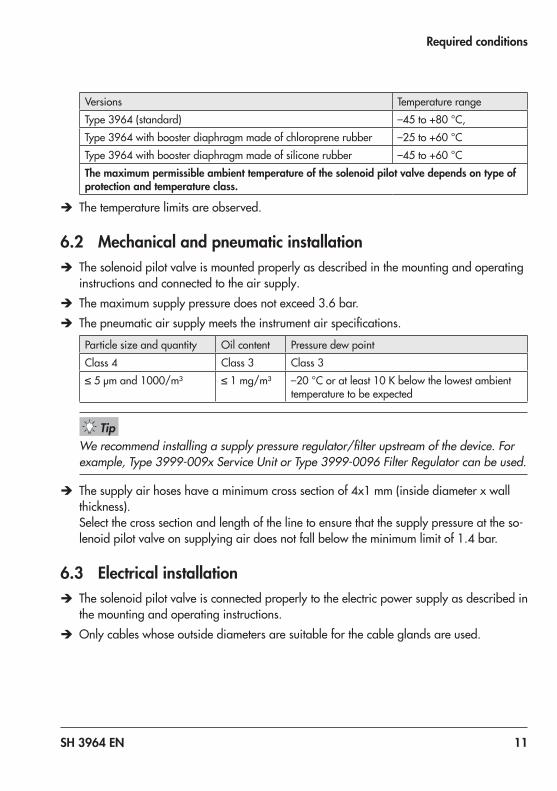
Versions Temperature rangeType 3964 (standard) –45 to +80 °C,Type 3964 with booster diaphragm made of chloroprene rubber –25 to +60 °CType 3964 with booster diaphragm made of silicone rubber –45 to +60 °C The maximum permissible ambient temperature of the solenoid pilot valve depends on type of protection and temperature class.
Î The temperature limits are observed.
6.2 Mechanical and pneumatic installation Î The solenoid pilot valve is mounted properly as described in the mounting and operating instructions and connected to the air supply.
Î The maximum supply pressure does not exceed 3.6 bar. Î The pneumatic air supply meets the instrument air specifications.
Particle size and quantity Oil content Pressure dew pointClass 4 Class 3 Class 3≤ 5 µm and 1000/m³ ≤ 1 mg/m³ –20 °C or at least 10 K below the lowest ambient
temperature to be expected
We recommend installing a supply pressure regulator/filter upstream of the device. For example, Type 3999-009x Service Unit or Type 3999-0096 Filter Regulator can be used.
Î The supply air hoses have a minimum cross section of 4x1 mm (inside diameter x wall thickness).Select the cross section and length of the line to ensure that the supply pressure at the so-lenoid pilot valve on supplying air does not fall below the minimum limit of 1.4 bar.
6.3 Electrical installation Î The solenoid pilot valve is connected properly to the electric power supply as described in the mounting and operating instructions.
Î Only cables whose outside diameters are suitable for the cable glands are used.
Tip

12 SH 3964 EN
Proof testing
Î The electrical cables in Ex i circuits comply with the data that planning was based on. Î The cable glands and enclosure cover screws are fastened tightly to ensure that the de-gree of protection is met.
Î The installation requirements for the applicable explosion protection measures are ob-served.
Î The special conditions specified in the explosion protection certificates are observed.
7 Proof testingThe proof test interval and the extent of testing lie within the operator's responsibility. The operator must draw up a test plan, in which the proof tests and the interval between them are specified. We recommend summarizing the requirements of the proof test in a check-list.
Risk of dangerous failure due to malfunction in the event of emergency (actuator is not vented or the valve does not move to the fail-safe position).
Î Only use devices in safety-instrumented systems that have passed the proof test according to the test plan drawn up by the operator.
Regularly check the safety-instrumented function of the entire SIS loop. The test intervals are determined, for example on calculating each single SIS loop in a plant (PFDavg).
7.1 Visual inspection to avoid systematic failureTo avoid systematic failure, inspect the solenoid pilot valve regularly. The frequency and the scope of the inspection lie within the operator's responsibility. Take application-specific influ-ences into account, such as: − Dirt blocking the pneumatic connections − Corrosion (destruction primarily of metals due to chemical and physical processes) − Material fatigue − Aging (damage caused to organic materials, e.g. plastics or elastomers, by exposure to
light and heat)
WARNING!

SH 3964 EN 13
Proof testing
− Chemical attack (organic materials, e.g. plastics or elastomer, which swell, leach out or decompose due to exposure to chemicals)
Risk of malfunction due to the use of unauthorized parts. Î Only use original parts to replace worn parts.
7.2 Function testingRegularly check the safety function according to the test plan drawn up by the operator.
Record any device faults and e-mail ([email protected]) them to SAMSON.
Î Install the pneumatic connection according to Mounting and Operating Instructions EB 3964.
Î Apply the nominal voltage UN specified in Table 3 to the solenoid pilot valve. Î Check whether the valve moves to its end position on demand. Î De-energize the solenoid pilot valve. Î Check whether the actuator is fully vented within the demanded time (fail-safe position).
You can connect a pressure gauge to check whether the actuator has completely vented.
Î Record the valve transit time and compare it to the time the valve took at start-up and during proof tests.
NOTICE!
Note
Tip

14 SH 3964 EN
Maintenance and repair
Proof testA full stroke test must be performed as the proof test. The following value can be used for Proof Test Coverage to calculate PFDavg:
PTC (Proof Test Coverage) = 95 % for a proof test
8 Maintenance and repairOnly perform the work on the solenoid pilot valve described in u EB 3964.
Safety function impaired due to incorrect repair. Î Only allow trained staff to perform service and repair work.
For devices operated in the low demand mode, a useful lifetime of 11 years (plus 1.5 years storage time) is confirmed by TÜV Rheinland® from the date of manufacture while taking into account the specific conditions of use specified in the Safety Manual and the Mounting and Operating Instructions.The results of the proof test must be assessed and the maintenance scheduled based on it. In particular, after changes (e.g. signs of aging in elastomers, changed switching times or leak-age etc.), it is essential that the manufacturer performs maintenance or repair work on the device.
MTC (Maintenance Coverage) > 99 %
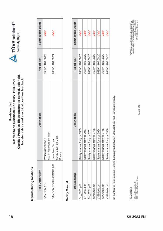
9 Safety-related data and certificatesThe safety-related data are listed in the following certificate.
NOTICE!

SH 3964 EN 15

16 SH 3964 EN

SH 3964 EN 17
R
evis
ion
List
re
ferr
ed to
on
Cer
tific
ate
No.
: 968
/V 1
160.
02/2
1 C
ertif
ied
Prod
uct:
Elec
trom
agne
tic c
ontr
ol, s
olen
oid,
bo
oste
r val
ves
and
elec
tric
al p
ositi
on f
eedb
ack
SA
MS
ON
AG
TÜ
V R
hein
land
Indu
strie
Ser
vice
Gm
bH
Aut
omat
ion
- Fun
ctio
nal S
afet
y (A
-FS
) W
eism
ülle
rstra
ße 3
Am
Gra
uen
Ste
in
6031
4 Fr
ankf
urt a
m M
ain
51
105
Köl
n / G
erm
any
P
age
1 of
3
Sa
fety
rel
ated
mod
ules
/ co
mpo
nent
s
Type
Des
igna
tion
Desc
riptio
n Re
port–
No.:
Certi
ficat
ion
Stat
us
3963
S
olen
oid
valve
96
8/V
116
0.00
/20
Val
id
3967
S
olen
oid
valve
96
8/V
116
0.00
/20
Val
id
3964
S
olen
oid
valve
96
8/V
116
0.00
/20
Val
id
3756
S
olen
oid
valve
96
8/V
116
0.00
/20
Val
id
3701
S
olen
oid
valve
96
8/V
116
0.00
/20
Val
id
3968
S
olen
oid
valve
96
8/V
116
0.00
/20
Val
id
3776
Li
mit
switc
h (w
ith o
ptio
n so
leno
id va
lve a
s w
ell a
s sa
fe in
dica
tion
of e
nd p
ositi
ons
) 96
8/V
116
0.00
/20
Val
id
TP-6033_Revision_List_Template.dotx Rev. v1.1
18 SH 3964 EN
R
evis
ion
List
re
ferr
ed to
on
Cer
tific
ate
No.
: 968
/V 1
160.
02/2
1 C
ertif
ied
Prod
uct:
Elec
trom
agne
tic c
ontr
ol, s
olen
oid,
bo
oste
r val
ves
and
elec
tric
al p
ositi
on f
eedb
ack
SA
MS
ON
AG
TÜ
V R
hein
land
Indu
strie
Ser
vice
Gm
bH
Aut
omat
ion
- Fun
ctio
nal S
afet
y (A
-FS
) W
eism
ülle
rstra
ße 3
Am
Gra
uen
Ste
in
6031
4 Fr
ankf
urt a
m M
ain
51
105
Köl
n / G
erm
any
P
age
2 of
3
M
anuf
actu
ring
loca
tions
Type
Des
igna
tion
Desc
riptio
n Re
port–
No.:
Certi
ficat
ion
Stat
us
SA
MS
ON
AG
W
eism
ülle
rstra
ße 3
60
314
Fran
kfur
t am
Mai
n 96
8/V
116
0.00
/20
Val
id
SA
MS
ON
RE
GU
LATI
ON
S.A
.S.
1 ru
e Je
an C
oron
a 69
120
Vau
lx-e
n-V
elin
Fr
ance
968/
V 1
160.
02/2
1 V
alid
Safe
ty M
anua
l
Docu
men
t No.
De
scrip
tion
Repo
rt–No
.: Ce
rtific
atio
n St
atus
SH
_396
3.pd
f S
afet
y m
anua
l for
type
396
3 96
8/V
116
0.00
/20
Val
id
SH
_396
7.pd
f S
afet
y m
anua
l for
type
396
7 96
8/V
116
0.00
/20
Val
id
SH
_370
1.pd
f S
afet
y m
anua
l for
type
370
1 96
8/V
116
0.00
/20
Val
id
e375
6sde
S
afet
y m
anua
l for
type
375
6 96
8/V
116
0.00
/20
Val
id
e396
4sde
S
afet
y m
anua
l for
type
396
4 96
8/V
116
0.00
/20
Val
id
e377
6sde
S
afet
y m
anua
l for
type
377
6 96
8/V
116
0.00
/20
Val
id
e396
8sde
S
afet
y m
anua
l for
type
396
8 96
8/V
116
0.00
/20
Val
id
The
cont
ent o
f thi
s R
evis
ion
List
has
bee
n ag
reed
bet
wee
n M
anuf
actu
rer a
nd C
ertif
icat
ion
Bod
y.

SH 3964 EN 19
R
evis
ion
List
re
ferr
ed to
on
Cer
tific
ate
No.
: 968
/V 1
160.
02/2
1 C
ertif
ied
Prod
uct:
Elec
trom
agne
tic c
ontr
ol, s
olen
oid,
bo
oste
r val
ves
and
elec
tric
al p
ositi
on f
eedb
ack
SA
MS
ON
AG
TÜ
V R
hein
land
Indu
strie
Ser
vice
Gm
bH
Aut
omat
ion
- Fun
ctio
nal S
afet
y (A
-FS
) W
eism
ülle
rstra
ße 3
Am
Gra
uen
Ste
in
6031
4 Fr
ankf
urt a
m M
ain
51
105
Köl
n / G
erm
any
P
age
3 of
3
R
evis
ion:
Date
Re
v.
Desc
riptio
n / C
hang
es
Auth
or
2021
-09-
08
1.0
Initi
al c
reat
ion,
bas
ed o
n R
epor
t-No.
: 968
/V 1
160.
02/2
1 JC
z/A
-FS

2021
-11-
03 ·
Engl
ish
SAMSON AKTIENGESELLSCHAFTWeismüllerstraße 3 · 60314 Frankfurt am Main, GermanyPhone: +49 69 4009-0 · Fax: +49 69 [email protected] · www.samsongroup.com
SH 3964 EN


![Samson. HWV 57 - accueil (data.bnf.fr) · Samson. - Awake the trumpet's lofty sound. - [6] (1995) Samson. - Awake the trumpet's lofty sound. - [6] (1995) Samson. - Awake the trumpet's](https://static.fdocuments.net/doc/165x107/600665197a8f42597414c65e/samson-hwv-57-accueil-databnffr-samson-awake-the-trumpets-lofty-sound.jpg)