SGC ALL TERRAIN LIFT KIT
12
SGC ALL TERRAIN LIFT KIT FITS CLUB CAR DS After installing this lift kit, the front wheels must be properly aligned. Failure to properly align the front wheels may result in decreased ability to control the Golf Cart which may result in a rollover or crash. !
Transcript of SGC ALL TERRAIN LIFT KIT

SGC ALL TERRAIN LIFT KIT FITS CLUB CAR DS
After installing this lift kit, the front wheels must be properly aligned. Failure to properly align the front wheels may result in decreased ability to control the Golf Cart which may result in a rollover or crash.
!

HD ALL TERRAIN LIFT KIT INSTALLATION INSTRUCTIONS
CLUB CAR DS
After installing this lift kit, the front wheels must be properly aligned. Failure to properly align the front wheels may result in decreased ability to control the golf cart which may result in a rollover or crash.
SEQ# USED PLACE NAME SPEC. QTY.
FRONT SUSPENSION
7 UPPER A-ARM TO SHOCK
HEX BOLT 5/16-18*2 2
FLAT WASHER 5/16 4
LOCK NUT 5/16 2
8 UPPER A-ARM TO CART
HEX BOLT 3/8-16*5 2
FLAT WASHER 3/8 4
LOCK NUT 3/8 2
9 TIE-ROD END TO SPINDLE EGG NECK BOLT 1/2-20*50 4
10 TIE-ROD END TO A-ARMS NUT 1/2-20 6
11 HEIM JOINT 4
REAR SUSPENSION
12 REAR LIFT BLOCK
HEX BOLT 7/16-14*7 1/8 4
LOCK NUT 7/16 4
FLAT WASHER 7/16 8
13 CENTERING PLATE
HEX BOLT 1/4-1/2 2
FLAT WASHER 1/4 4
LOCK NUT 1/4 2
CHECK LIST FOR HARDWARE
Page 1
Specifications are subject to change without prior notice.
(Bolt in bag#12 too long so packed separately)

To begin, be sure to engage the parking brake and switch your cart to “off”. Also make sure RUN/TOW switch is in TOW position.
1. Remove front bumper and retain. Remove front wheels. Remove dust cap, cotter pin, spindle nut and wheel hub. Retain hub and hardware.
2. Remove lower shock mounting bolt and nut on driver and passenger side. Shock does not need to be completely removed, only the lower bolt so the shock can be pushed up and out of the way. Remove spindles from leaf spring and drag link and tie rod end. Retain Hardware.
HD ALL TERRAIN LIFT KIT INSTALLATION INSTRUCTIONS
CLUB CAR DS
Page 2

3. Remove the four factory A-arm bolts and nuts. Remove factory A-arms, do not retain. Remove the four bolts and washers to detach factory suspension assembly and retain hardware. Factory suspension assembly will not be used.
4. Attach main suspension assembly #1 using hardware retained from step 3 and tighten. A floor jack is recommended to hold the suspension assembly in place while you get the bolts started.
1
HD ALL TERRAIN LIFT KIT INSTALLATION INSTRUCTIONS
CLUB CAR DS
Page 3

5. Install upper arm #2 on the cart using supplied hardware #8. Install lower end of factory shock on the upper arm using hardware #7.
6. Install heim joint #11 on the upper arm using supplied 1/2-20 nut. Install heim joint on the end of lower A-arm using supplied two 1/2-20 nuts.
2
2
8
7
7
11
11
HD ALL TERRAIN LIFT KIT INSTALLATION INSTRUCTIONS
CLUB CAR DS
Page 4
10
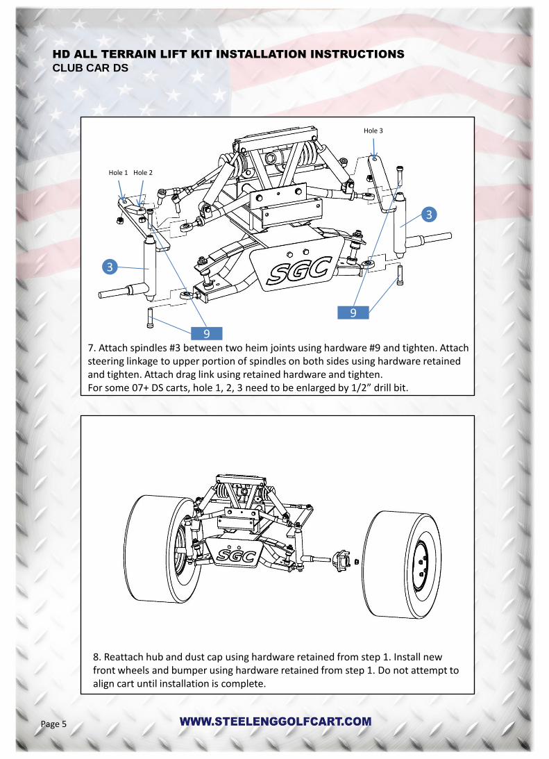
7. Attach spindles #3 between two heim joints using hardware #9 and tighten. Attach steering linkage to upper portion of spindles on both sides using hardware retained and tighten. Attach drag link using retained hardware and tighten. For some 07+ DS carts, hole 1, 2, 3 need to be enlarged by 1/2” drill bit.
8. Reattach hub and dust cap using hardware retained from step 1. Install new front wheels and bumper using hardware retained from step 1. Do not attempt to align cart until installation is complete.
3
3
9
9
HD ALL TERRAIN LIFT KIT INSTALLATION INSTRUCTIONS
CLUB CAR DS
Hole 1 Hole 2
Hole 3
Page 5
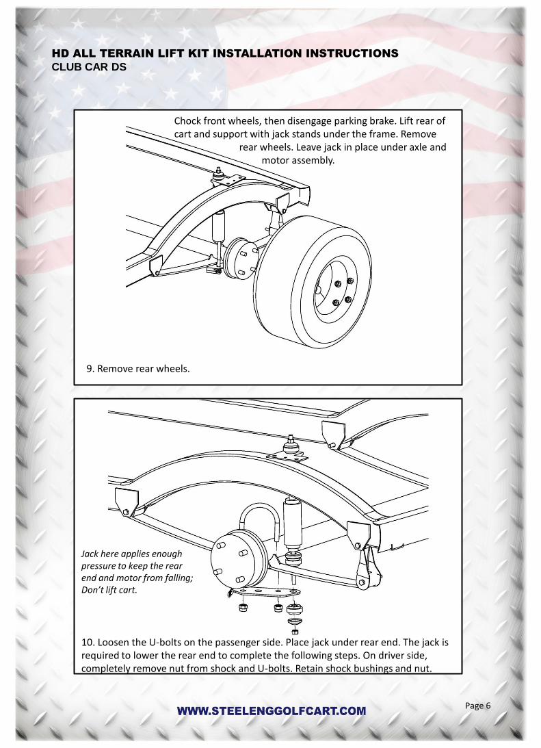
9. Remove rear wheels.
10. Loosen the U-bolts on the passenger side. Place jack under rear end. The jack is required to lower the rear end to complete the following steps. On driver side, completely remove nut from shock and U-bolts. Retain shock bushings and nut.
Chock front wheels, then disengage parking brake. Lift rear of cart and support with jack stands under the frame. Remove rear wheels. Leave jack in place under axle and motor assembly.
Jack here applies enough pressure to keep the rear end and motor from falling; Don’t lift cart.
HD ALL TERRAIN LIFT KIT INSTALLATION INSTRUCTIONS
CLUB CAR DS
Page 6

11. Using a 10mm socket and 13mm wrench remove hardware from rear leaf spring mount and front leaf spring mount. Retain hardware.
12. Place rear lift block #4 on the axle and under leaf spring. Ensure that top of lift block angles down toward the front of cart. Place rear shock plate#5 over leaf spring and attach shock to it. Attach hardware #13 on centering plate #6 then attach centering plate to factory shock plate. The bolt head and nut will fit into the center hole of the spring perch and factory lower bracket to aid in alignment of the riser and mounting plates.
6
4
5
13
HD ALL TERRAIN LIFT KIT INSTALLATION INSTRUCTIONS
CLUB CAR DS
Page 7

13. Route bolt from supplied hardware #12 through rear shock plate #5, rear lift block and factory shock plate. Using socket to tighten these four bolts evenly to ensure proper alignment.
14. Repeat on passenger side, use jack to lower axle and motor assembly as needed. Once complete, install wheels, lower cart and proceed with alignment on next page.
5
6
12
HD ALL TERRAIN LIFT KIT INSTALLATION INSTRUCTIONS
CLUB CAR DS
Page 8

ALIGNMENT INSTRUCTIONS
IMPORTANT: Both Camber and Toe must be adjusted on this model. To adjust for proper camber (the vertical tilt of the wheels), use a framing square, level, or some other means of verifying that the tire is at a 90 degree angle to the ground. Adjust camber to 90 degrees using the two nuts on the bottom heim joint. If adjusting the camber to 90 degrees is not possible using only the adjustment on the bottom heim joint, then the top heim joint must be disconnected from the spindle, rotated, then reassembled and checked as necessary to achieve the correct camber. IMPORTANT: Be sure to retighten all adjustment points after adjustments are made. To adjust Toe, ensure the wheels are pointing straight forward. Find a common point to measure from on the inside front and inside rear of the front tires. Adjust until the front measurement is 1/4” to 3/8” greater than the rear measurement. Loosen nut on both tie rod ends. Adjust using a wrench to desired alignment. If steering wheel is not properly oriented after adjusting toe-out, adjust steering box tie rod to align steering wheel if needed. Loosen tie rod lock nuts and turn steering box tie rod clockwise or counter clockwise to adjust steering wheel. IMPORTANT: Ensure that after this adjustment, both wheels toe out from the cart’s centerline equally. Once tightened, roll the cart back 15-20 feet and then forward again to check. NOTE: Be sure to use thread locking adhesive on upper and lower heim joint spindle bolts.
Page 9